EP2000643B1 - Système d'échappement - Google Patents
Système d'échappement Download PDFInfo
- Publication number
- EP2000643B1 EP2000643B1 EP08157029A EP08157029A EP2000643B1 EP 2000643 B1 EP2000643 B1 EP 2000643B1 EP 08157029 A EP08157029 A EP 08157029A EP 08157029 A EP08157029 A EP 08157029A EP 2000643 B1 EP2000643 B1 EP 2000643B1
- Authority
- EP
- European Patent Office
- Prior art keywords
- sound transmission
- exhaust
- transmission device
- combustion engine
- exhaust system
- Prior art date
- Legal status (The legal status is an assumption and is not a legal conclusion. Google has not performed a legal analysis and makes no representation as to the accuracy of the status listed.)
- Not-in-force
Links
Images
Classifications
-
- F—MECHANICAL ENGINEERING; LIGHTING; HEATING; WEAPONS; BLASTING
- F01—MACHINES OR ENGINES IN GENERAL; ENGINE PLANTS IN GENERAL; STEAM ENGINES
- F01N—GAS-FLOW SILENCERS OR EXHAUST APPARATUS FOR MACHINES OR ENGINES IN GENERAL; GAS-FLOW SILENCERS OR EXHAUST APPARATUS FOR INTERNAL-COMBUSTION ENGINES
- F01N13/00—Exhaust or silencing apparatus characterised by constructional features
- F01N13/02—Exhaust or silencing apparatus characterised by constructional features having two or more separate silencers in series
-
- F—MECHANICAL ENGINEERING; LIGHTING; HEATING; WEAPONS; BLASTING
- F01—MACHINES OR ENGINES IN GENERAL; ENGINE PLANTS IN GENERAL; STEAM ENGINES
- F01N—GAS-FLOW SILENCERS OR EXHAUST APPARATUS FOR MACHINES OR ENGINES IN GENERAL; GAS-FLOW SILENCERS OR EXHAUST APPARATUS FOR INTERNAL-COMBUSTION ENGINES
- F01N13/00—Exhaust or silencing apparatus characterised by constructional features
- F01N13/011—Exhaust or silencing apparatus characterised by constructional features having two or more purifying devices arranged in parallel
-
- F—MECHANICAL ENGINEERING; LIGHTING; HEATING; WEAPONS; BLASTING
- F01—MACHINES OR ENGINES IN GENERAL; ENGINE PLANTS IN GENERAL; STEAM ENGINES
- F01N—GAS-FLOW SILENCERS OR EXHAUST APPARATUS FOR MACHINES OR ENGINES IN GENERAL; GAS-FLOW SILENCERS OR EXHAUST APPARATUS FOR INTERNAL-COMBUSTION ENGINES
- F01N13/00—Exhaust or silencing apparatus characterised by constructional features
- F01N13/08—Other arrangements or adaptations of exhaust conduits
- F01N13/10—Other arrangements or adaptations of exhaust conduits of exhaust manifolds
- F01N13/107—More than one exhaust manifold or exhaust collector
Definitions
- the present invention relates to an exhaust system for an internal combustion engine, in particular in a motor vehicle, having the features of the preamble of claim 1.
- the exhaust gases are often fed from the two cylinder banks via two manifolds in two exhaust lines to a common muffler or two separate mufflers.
- the two exhaust strands run in the vehicle on the underbody in a tunnel which regularly has heat shields upwards and to the side. Down below, the underfloor clearance is an imaginary border of the tunnel dar.
- a center silencer which must be located in the middle of the system. In this case, each exhaust tract a separate center muffler can be assigned.
- both exhaust strands can be assigned a common middle silencer.
- the respective middle silencer must also be accommodated in the tunnel, which regularly leads to space problems, since the respective Middle silencer must have a certain minimum volume in order to fulfill its acoustic function.
- an exhaust system which has two separate exhaust lines for discharging exhaust gases of an internal combustion engine. Furthermore, the known exhaust system comprises a switchable sound transmission device, which couples the two exhaust gas lines for the transmission of airborne sound with each other. With the aid of a control device, the sound transmission device can be activated and deactivated, this being done as a function of at least one operating parameter of the internal combustion engine. In this case, for example, the rotational speed and / or the load of the internal combustion engine are suitable as operating parameters.
- the one sound transmission device is arranged downstream of two catalysts, which are arranged in each one of the exhaust gas lines. Furthermore, the one sound transmission device is positioned upstream of silencers, which are assigned to the individual exhaust gas trains separately and each form a center silencer and a rear silencer.
- the known exhaust system is suitably operated so that at low speeds, the sound transmission device is active. Silencers associated with the exhaust lines are acoustically designed for noise frequencies that occur at low speeds. At higher speeds, the sound transmission device is deactivated, whereby the effective interference frequencies due to the targeted assignment of the separate exhaust lines to individual cylinders of the internal combustion engine is halved. Thus, for two speed ranges, which are related to each other via the interference frequencies, an effective sound attenuation can be achieved.
- the disadvantage here is the limitation of the damping effect on only two speed ranges. Furthermore, activation of the sound transmission device at low speeds may result in a reduction in the available engine torque due to adverse effects on the charge cycle of the cylinders of the internal combustion engine.
- the present invention is concerned with the problem, for an exhaust system of the type mentioned, to provide an improved embodiment, which is characterized in particular by the fact that the required space is reduced.
- the invention is based on the general idea to dispense with a middle silencer.
- the associated with the installation of a middle silencer space problems can be avoided.
- This is made possible by the fact that the two exhaust gas lines are acoustically coupled with two switchable sound transmission devices, which are arranged spaced apart in the exhaust gas flow direction.
- an increased variability for the adjustable switching states can be realized.
- Of increased interest are at least three different switching states, namely a first switching state in which both sound transmission devices are deactivated, a second switching state in which one sound transmission device is activated while the other sound transmission device is deactivated and a third switching state in which both sound transmission devices activated are. It has been found that the different switching states result in significant effects on the torque of the engine equipped with the exhaust system.
- the torque can be significantly increased if this low rotational speed of the internal combustion engine is assigned, ie operating states in which a high torque is particularly desirable.
- the damping effect of the exhaust system can be better adapted to different operating states of the internal combustion engine by the three different switching states. With appropriate design and positioning of the two sound transmission devices can now be the extent of the damping effect of the exhaust system improved so far that according to the invention can be dispensed with a middle silencer.
- the sound transmission devices are arranged in the exhaust system according to the invention downstream of catalysts, which are provided in both exhaust lines.
- An embodiment has proven to be particularly advantageous in which the upstream first sound transmission device is deactivated in the second operating state, while the downstream second sound transmission device is activated.
- the torque can be increased for average speeds.
- a control device assigns the switching states to different speed ranges.
- the first switching state is associated with a lower speed range
- the second switching state is associated with a medium speed range
- the third switching state is associated with an upper speed range.
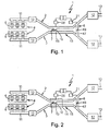
- an exhaust system 1 comprises two separate exhaust lines 2 and 3.
- the exhaust system 1 serves to dissipate the exhaust gases in an internal combustion engine 4, which may be arranged in particular in a motor vehicle.
- the two exhaust gas lines 2, 3 are assigned to different cylinders 5 of the internal combustion engine 4. In the example, a six-cylinder engine is shown without limiting the generality.
- the two exhaust gas lines 2, 3 are each assigned to a group of cylinders 5, which are selected such that the cylinders 5 of a cylinder group and the cylinders 5 of the other cylinder group have their working strokes each alternating.
- the cylinder groups can be selected so that parallel-acting cylinders are each arranged in different cylinder groups. This is especially true for larger engines, such as V-eight or V-twelve engines.
- the exhaust system 1 also has a first switchable sound transmission device 7, which is designed so that it can couple the two exhaust gas lines 2, 3 for the transmission of airborne sound.
- the exhaust system 1 according to the invention comprises a second switchable sound transmission device 8, which is designed such that it the two exhaust gas lines 2, 3 downstream of the first Sound transmission device 7 can couple to each other for the transmission of airborne sound.
- a control device 9 For switching or for actuating the two sound transmission devices 7, a control device 9 is provided. This is designed so that it can control the two sound transmission devices 7, 8 as a function of at least one operating parameter of the internal combustion engine 4 for activating and deactivating.
- the activated state a sound transmission between the two exhaust lines 2, 3 by the respective sound transmission device 7, 8.
- the deactivated state the sound transmission between the two exhaust lines 2, 3 is omitted by the respective sound transmission device 7, 8.
- the control device 9 is also according to the invention configured so that it can control the two sound transmission devices 7, 8 in response to the at least one operating parameter of the internal combustion engine 4 for the realization of at least three different switching states. In a first switching state, both sound transmission devices 7, 8 are deactivated.
- the control device 9 controls the sound transmission devices 7, 8 for realizing the second switching state such that the upstream first sound transmission device 7 is deactivated and that the downstream second sound transmission device 8 is activated.
- the control device 9 preferably uses a rotational speed of the internal combustion engine 4 in order to actuate the sound transmission devices 7, 8 as a function of the rotational speed.
- control device 9 is configured so that it divides the speed range of the internal combustion engine 4 in total into three speed ranges. In a lower speed range, the control device 9 actuates the sound transmission devices 7, 8 for setting the first switching state. In a medium speed range, the control device 9 adjusts the second switching state at the sound transmission devices 7, 8. In an upper speed range, the control device 9 then realizes the third switching state.
- the corresponding speed information is received by the control device 9, e.g. from an engine control unit, not shown here.
- the control device 9 can be integrated into the hardware of such an engine control unit or implemented in software.
- the lower speed range may include speeds up to 1,500 RPM, while the medium speed range may include speeds from about 1,500 RPM to about 2,500 RPM.
- the upper speed range can then have speeds from 2,500 rpm.
- each exhaust line 2 includes a muffler 12.
- These mufflers 12 may in particular So-called rear muffler act whose outlet leads to the tailpipe 13 of the respective exhaust line 2, 3.
- each one of the exhaust lines 2, 3 associated mufflers 12 may in principle also be provided a common muffler, which is then assigned to both exhaust lines 2, 3.
- Fig. 2 In principle, it is possible to equip the exhaust system 1 with at least one middle silencer 14, which in particular can be assigned jointly to both exhaust lines 2, 3. Depending on the application and depending on the design of the exhaust system 1, it is by the use of the two sound transmission devices 7, 8 according to Fig. 1 possible to dispense with such a middle silencer 14 and yet to ensure adequate sound attenuation.
- the first sound transmission device 7 at the two exhaust gas lines 2, 3 downstream the catalysts 10 are arranged. Furthermore, the first sound transmission device 7 is located upstream of the silencer 12. The second sound transmission device 8 is arranged on both exhaust gas lines 2, 3 upstream of the two silencers 12. In addition, the second sound transmission device 8 is located downstream of the first sound transmission device 7 and thus downstream of the catalysts 10.
- the respective exhaust line 2, 3 upstream of the second sound transmission device 8 no further muffler.
- other exhaust gas treatment devices in the respective exhaust gas line 2, 3, in particular also downstream of the first sound transmission device 7 may be arranged upstream of the second sound transmission device 8, such as a particulate filter or an SCR catalyst or a Denox catalyst, however, none is designed exclusively as a muffler Component more available. As a result, the pressure loss in the respective exhaust line 2, 3 can be reduced.
- the two exhaust gas strands 2, 3 can run parallel to one another in a middle region 15.
- This middle area extends in the installed state in a tunnel, which is located on the underbody of the respective vehicle.
- the first sound transmission device 7 is arranged on the respective exhaust gas line 2, 3 in this central region 15, which extends in the tunnel.
- a positioning can be selected in which it is located in the middle region 15 running in the tunnel.
- the first sound transmission device 7 is preferably arranged in the respective exhaust gas line 2, 3 in a region which, relative to a flow path leading from the internal combustion engine 4 to the respective muffler 12, is less than or equal to 50% of this flow path.
- the first sound transmission device 7 may be positioned at about 30% to 50% or at about 40% to 50% or at about 50% of this flow path.
- this is in a range greater than or equal to 50% of said flow path.
- the second sound transmission device 8 is in a range of about 50% to 100% or from about 70% to 100% or from about 80% to 100% of the flow path. It has been shown that an embodiment is particularly advantageous if a flow path between the two sound transmission devices 7, 8 within the respective exhaust line 2, 3 is at least 50 cm.
- the respective sound transmission device 7 may have a connecting pipe 16 or 17 which connects the two exhaust gas strands 2, 3 communicating with each other. Furthermore, the respective sound transmission device 7 each have an actuator 18 and 19, z. As a slider or a flap or aperture, which designed so is that so that the respective connecting pipe 16, 17 can be opened and locked. Furthermore, an actuator 20 or 21 is here in each case still indicated, which serves to drive the respective actuator 18, 19 and which can be actuated or controlled by means of the control device 9.
- the respective sound transmission device 7, 8 configured so that only two switching states are adjustable to it, namely an active state with maximum sound transmission or maximum open cross section in the respective connecting pipe 16, 17 and an inactive state with no or minimal sound transmission or
- at least one of the sound transmission devices 7, 8 can realize at least one intermediate state in which the sound transmission between the exhaust gas strands 2, 3 is only partially activated or partially activated is only partially deactivated, so that in particular the flow cross-section in the respective connecting pipe 16, 17 is only partially opened or only partially blocked.
- the exhaust system 1 operates as follows:
- both sound transmission devices 7, 8 are deactivated.
- the exhaust gases of the two cylinder banks 6 are thus removed separately, without resulting in an acoustic coupling between the two exhaust gas lines 2, 3.
- This can be done also avoid interactions between the acoustic coupling and gas exchange processes. Such interactions can occur in the presence of an acoustic coupling, especially at low speeds, since sound waves are also pressure pulsations, which can also propagate upstream and thereby adversely affect charge exchange operations.
- the middle speed range ie above 1,500 rpm and below 2,500 rpm, the second sound transmission device 8 is activated.
- the first sound transmission device 7 is activated, whereby additional torque is provided.
- the common rear muffler or the two separate muffler 12 and possibly the center muffler 14 can be realized for the respective speed range effective sound attenuation.
Landscapes
- Engineering & Computer Science (AREA)
- Chemical & Material Sciences (AREA)
- Combustion & Propulsion (AREA)
- Mechanical Engineering (AREA)
- General Engineering & Computer Science (AREA)
- Exhaust Silencers (AREA)
Claims (12)
- Installation d'échappement pour un moteur à combustion interne (4), en particulier sur un véhicule automobile, présentant- deux branches d'échappement (2, 3) séparées pour l'évacuation de gaz brûlés d'un moteur à combustion interne (4), qui présentent chacune un catalyseur (10),- un premier dispositif de transmission de son (7) commutable, qui couple les deux branches d'échappement (2, 3) l'une avec l'autre pour la transmission de son aérien,- un dispositif de commande (9) pour l'activation et la désactivation du premier dispositif de transmission de son (7) en fonction d'au moins un paramètre de service du moteur à combustion interne (4),- un second dispositif de transmission de son (8) commutable avec le dispositif de commande (9) étant prévu, lequel couple les deux branches d'échappement (2, 3) en aval du premier dispositif de transmission de son (7) pour la transmission de son aérien,- le dispositif de commande (9) étant conçu de telle sorte que, en fonction du au moins un paramètre de service du moteur à combustion interne (4), permettant au moins trois états de commutation pour les deux dispositifs de transmission de son (7, 8), à savoir- un premier état de commutation dans lequel les deux dispositifs de transmission de son (7, 8) sont désactivés,- un second état de commutation dans lequel l'un des dispositifs de commutation (7, 8) est activé, alors que l'autre dispositif de transmission de son (7, 8) est désactivé,- un troisième état de commutation dans lequel les deux dispositifs de transmission de son (7, 8) sont activés,caractérisé- en ce que le premier dispositif de transmission de son (7) est disposé sur les deux branches d'échappement (2, 3) en aval du catalyseur (10) respectif,- en ce qu'aucun silencieux central n'est prévu.
- Installation d'échappement selon la revendication 1,
caractérisé en ce que,
dans le second état de commutation, le premier dispositif de transmission de son (7) situé en amont est désactivé, alors que le second dispositif de transmission de son (8) situé en aval est activé. - Installation d'échappement selon la revendication 1 ou 2,
caractérisée en ce que
le dispositif de commande (9) utilise un régime du moteur à combustion interne (4) comme paramètre de service pour la commutation des dispositifs de transmission de son (7, 8) - Installation d'échappement selon l'une quelconque des revendications 1 à 3,
caractérisée en ce que
le dispositif de commande (9) est conçu de telle sorte- qu'il règle le premier état de commutation dans une plage de régime inférieure,- qu'il règle le second état de commutation dans une plage de régime moyenne,- qu'il règle le troisième état de commutation dans une plage de régime supérieure. - Installation d'échappement selon l'une quelconque des revendications 1 à 4,
caractérisée- en ce que les deux branches d'échappement (2, 3) sont attribuées respectivement à un groupe de cylindres du moteur à combustion interne (4), les cylindres (5) de l'un des groupes de cylindres et les cylindres (5) de l'autre groupe de cylindres effectuant leurs courses de travail en alternance ou de façon synchrone, et/ou- en ce que les deux branches d'échappement (2, 3) sont attribuées respectivement à un banc de cylindres (6) d'un moteur à combustion interne (4) conçu comme moteur en V. - Installation d'échappement selon l'une quelconque des revendications 1 à 5,
caractérisée en ce que
le second dispositif de transmission de son (8) est disposé sur les deux branches d'échappement (2, 3) en amont de respectivement un silencieux final (12) séparé ou commun. - Installation d'échappement selon l'une quelconque des revendications 1 à 6,
caractérisée en ce que
la branche d'échappement (2, 3) respective ne contient pas de silencieux en amont du second dispositif de transmission de son (8). - Installation d'échappement selon l'une quelconque des revendications 1 à 7,
caractérisée en ce que
le premier dispositif de transmission de son (7) est disposé dans la branche d'échappement (2, 3) respective dans une zone correspondant à moins de 50 % ou à peu près à 50 % ou à environ 30 % jusqu'à 50 % ou à environ 40 % jusqu'à 50 % d'une course d'écoulement entre le moteur à combustion interne (4) et un silencieux (12) attribué à la branche d'échappement (2, 3) respective. - Installation d'échappement selon l'une quelconque des revendications 1 à 8,
caractérisée en ce que
le second dispositif de transmission de son (8) est disposé dans la branche d'échappement (2, 3) respective dans une zone correspondant à plus de 50 % ou égale à 50 % ou à environ 50 % jusqu'à 100 % ou à environ 70 % jusqu'à 100 % ou à environ 80 % jusqu'à 100 % d'une course d'écoulement entre le moteur à combustion interne (4) et un silencieux (12) attribué à la branche d'échappement (2, 3) respective. - Installation d'échappement selon l'une quelconque des revendications 1 à 9,
caractérisée en ce que
le premier dispositif de transmission de son (7) et/ou le second dispositif de transmission de son (8) est/sont disposé(s) sur les deux branches d'échappement (2, 3) dans une zone (15) dans laquelle les deux branches d'échappement (2, 3) sont agencées dans l'état monté dans un tunnel du véhicule. - Installation d'échappement selon l'une quelconque des revendications 1 à 10,
caractérisée en ce que
la course d'écoulement entre les deux dispositifs de transmission de son (7, 8) est d'au moins 50 cm dans la branche d'échappement (2, 3) respective. - Installation d'échappement selon l'une quelconque des revendications 1 à 11,
caractérisée- en ce que le dispositif de transmission de son (7, 8) respectif présente un tuyau de liaison (16, 17) qui relie les deux branches d'échappement (2, 3) de façon communicante l'une avec l'autre et/ou- en ce que le dispositif de transmission de son (7, 8) respectif présente un actionneur (18, 19) pour l'ouverture et la fermeture du tuyau de liaison (16, 17) respectif.
Applications Claiming Priority (1)
| Application Number | Priority Date | Filing Date | Title |
|---|---|---|---|
| DE102007026812A DE102007026812A1 (de) | 2007-06-06 | 2007-06-06 | Abgasanlage |
Publications (2)
| Publication Number | Publication Date |
|---|---|
| EP2000643A1 EP2000643A1 (fr) | 2008-12-10 |
| EP2000643B1 true EP2000643B1 (fr) | 2011-07-27 |
Family
ID=39735108
Family Applications (1)
| Application Number | Title | Priority Date | Filing Date |
|---|---|---|---|
| EP08157029A Not-in-force EP2000643B1 (fr) | 2007-06-06 | 2008-05-28 | Système d'échappement |
Country Status (5)
| Country | Link |
|---|---|
| US (1) | US7703574B2 (fr) |
| EP (1) | EP2000643B1 (fr) |
| AT (1) | ATE518051T1 (fr) |
| DE (1) | DE102007026812A1 (fr) |
| ES (1) | ES2370452T3 (fr) |
Families Citing this family (33)
| Publication number | Priority date | Publication date | Assignee | Title |
|---|---|---|---|---|
| US8365522B2 (en) * | 2008-08-21 | 2013-02-05 | Emcon Technologies Llc | Dual exhaust system with independent valve control |
| DE102009032214B4 (de) | 2009-07-06 | 2023-10-19 | Dr. Ing. H.C. F. Porsche Aktiengesellschaft | Abgasanlage einer Brennkraftmaschine |
| DE102009032213B4 (de) | 2009-07-06 | 2024-05-16 | Dr. Ing. H.C. F. Porsche Aktiengesellschaft | Abgasanlage einer Brennkraftmaschine |
| DE102009032215A1 (de) | 2009-07-06 | 2011-01-27 | Dr. Ing. H.C. F. Porsche Aktiengesellschaft | Abgasanlage einer Brennkraftmaschine |
| DE102010008277B4 (de) | 2010-02-17 | 2023-10-12 | Dr. Ing. H.C. F. Porsche Aktiengesellschaft | Abgasanlage einer Brennkraftmaschine |
| DE102010017487A1 (de) | 2010-06-21 | 2011-12-22 | Dr. Ing. H.C. F. Porsche Aktiengesellschaft | Abgasanlage eines Kraftfahrzeugs |
| KR101195148B1 (ko) | 2010-07-29 | 2012-10-29 | 삼성중공업 주식회사 | 배기 가스 유해 물질 저감 시스템 및 이를 포함하는 선박 |
| US8309045B2 (en) | 2011-02-11 | 2012-11-13 | General Electric Company | System and method for controlling emissions in a combustion system |
| DE102011051690B4 (de) * | 2011-07-08 | 2023-06-29 | Dr. Ing. H.C. F. Porsche Aktiengesellschaft | Steuerungseinrichtung eines Kraftfahrzeugs mit einem Geräuschübertragungssystem und einem Abgassystem |
| JP5895577B2 (ja) * | 2012-02-14 | 2016-03-30 | スズキ株式会社 | エンジンの排気制御装置 |
| EP2657494A1 (fr) * | 2012-04-23 | 2013-10-30 | Ford Global Technologies, LLC | Moteur à combustion à allumage commandé avec une section murale séparant au moins deux cylindres |
| DE102012112433A1 (de) * | 2012-12-17 | 2014-06-18 | Dr. Ing. H.C. F. Porsche Aktiengesellschaft | Abgasanlage für eine Brennkraftmaschine |
| US9067176B2 (en) | 2013-03-15 | 2015-06-30 | Honeywell International, Inc. | Specialized ammonia injection grid with the dual purpose of suppressing noise |
| KR101511541B1 (ko) * | 2013-11-15 | 2015-04-13 | 현대자동차주식회사 | Cda 엔진용 듀얼 배기계 구조 |
| DE102014011618B4 (de) * | 2014-08-01 | 2016-11-10 | Audi Ag | Abgasanlage für eine Brennkraftmaschine |
| US10443479B2 (en) | 2014-10-30 | 2019-10-15 | Roush Enterprises, Inc. | Exhaust control system |
| JP5945018B1 (ja) * | 2015-01-30 | 2016-07-05 | 本田技研工業株式会社 | 排気マフラー |
| DE102015211460A1 (de) * | 2015-06-22 | 2016-12-22 | Bayerische Motoren Werke Aktiengesellschaft | Abgasanlage |
| DE102015011175B4 (de) * | 2015-08-27 | 2021-01-14 | Audi Ag | Abgasanlage für eine Brennkraftmaschine |
| EP3141720B1 (fr) * | 2015-09-10 | 2018-10-31 | Akrapovic d.d. | Système d'échappement pour un moteur d'automobile à combustion interne |
| JP6551132B2 (ja) * | 2015-10-13 | 2019-07-31 | スズキ株式会社 | エンジンの排気制御装置 |
| WO2017079156A1 (fr) | 2015-11-02 | 2017-05-11 | Roush Enterprises, Inc. | Silencieux à voies d'échappement sélectionnées |
| KR101762280B1 (ko) * | 2016-03-28 | 2017-07-28 | 현대자동차주식회사 | 중앙 관통형 능동밸브 구조 |
| US20170298802A1 (en) * | 2016-04-14 | 2017-10-19 | Hyundai Motor Company | Structure of exhaust pipe |
| US10287937B2 (en) * | 2016-06-17 | 2019-05-14 | Ford Global Technologies, Llc | Exhaust system for an engine |
| KR101762281B1 (ko) * | 2016-06-20 | 2017-07-31 | 현대자동차주식회사 | 가변 합류부 구조를 갖는 배기파이프 구조 |
| US20180223709A1 (en) * | 2017-02-06 | 2018-08-09 | GM Global Technology Operations LLC | Function based continuous exhaust valve control |
| US10837333B2 (en) * | 2017-12-28 | 2020-11-17 | Ford Global Technologies, Llc | Exhaust system having tunable exhaust sound |
| US10358956B1 (en) | 2018-07-09 | 2019-07-23 | Faurecia Emissions Control Technologies, Usa, Llc | Exhaust valve and active noise control for compact exhaust system |
| KR102096998B1 (ko) * | 2018-08-31 | 2020-04-03 | 정지연 | 배기가스 배기장치 |
| US11401851B1 (en) * | 2019-06-18 | 2022-08-02 | Tilahun Anshu | Vehicular exhaust system |
| KR102768237B1 (ko) * | 2020-07-14 | 2025-02-18 | 쩌지앙 길리 홀딩 그룹 씨오., 엘티디. | 배기 소음 장치, 시스템, 차량 및 배기 소음 방법 |
| US11598236B2 (en) * | 2020-09-28 | 2023-03-07 | Ford Global Technologies, Llc | Exhaust system |
Family Cites Families (27)
| Publication number | Priority date | Publication date | Assignee | Title |
|---|---|---|---|---|
| US2180843A (en) * | 1933-03-29 | 1939-11-21 | Sperry Gyroscope Co Inc | Noise reducing means for cabin aircraft |
| US3653212A (en) * | 1970-10-30 | 1972-04-04 | Gen Motors Corp | Exhaust emission control system |
| DE2322057A1 (de) * | 1973-05-02 | 1974-11-21 | Porsche Ag | Vorrichtung zum katalytischen nachverbrennen von abgasen einer mehrzylindrigen brennkraftmaschine |
| JPS58178820A (ja) * | 1982-04-14 | 1983-10-19 | Yamaha Motor Co Ltd | 自動二輪車の排気装置 |
| US4527392A (en) * | 1983-04-20 | 1985-07-09 | Hino Jidosha Kogyo Kabushiki Kaisha | Bypass valve actuator for inertia supercharging in multicylinder engines |
| JPS60247006A (ja) * | 1984-05-22 | 1985-12-06 | Yoichi Yamazaki | 多気筒エンジンの排気装置 |
| GB2161215A (en) * | 1984-07-05 | 1986-01-08 | Shelburne Inc | Exhaust systems for internal combustion engines |
| JPH0629548B2 (ja) * | 1985-03-18 | 1994-04-20 | ヤマハ発動機株式会社 | 多気筒エンジンの排気装置 |
| GB8516420D0 (en) * | 1985-06-28 | 1985-07-31 | Ontario Research Foundation | Diesel particulate traps |
| DE3740238A1 (de) * | 1986-12-04 | 1988-06-23 | Audi Ag | Abgasanlage fuer eine brennkraftmaschine mit zwei zylinderbaenken |
| JPH086576B2 (ja) * | 1987-06-08 | 1996-01-24 | 日産自動車株式会社 | 多気筒エンジンの排気装置 |
| JPH0544503Y2 (fr) * | 1988-07-29 | 1993-11-11 | ||
| GB8923615D0 (en) * | 1989-10-19 | 1989-12-06 | Dewandre Co Ltd C | Exhaust system |
| JP3053823B2 (ja) * | 1989-10-23 | 2000-06-19 | カルソニック株式会社 | 車両用排気装置の制御方法 |
| JP2586164B2 (ja) * | 1990-02-03 | 1997-02-26 | トヨタ自動車株式会社 | 内燃機関の排気系 |
| DE4106918B4 (de) | 1991-03-05 | 2006-11-09 | Bayerische Motoren Werke Ag | Mehrzylinder-Brennkraftmaschine mit einer Ein-/Auslaß-Steuerung mit Überschneidung der Steuerzeiten sowie einer mehrflutigen Abgasanlage |
| US5144799A (en) * | 1991-07-18 | 1992-09-08 | Barth Randolph S | Crossfire calibrated exhaust system |
| US5317112A (en) * | 1991-10-16 | 1994-05-31 | Hyundai Motor Company | Intake silencer of the variable type for use in motor vehicle |
| US5937640A (en) * | 1997-12-10 | 1999-08-17 | Ford Global Technologies, Inc. | Thermal management system for catalytic converters |
| DE19840096A1 (de) * | 1998-09-03 | 2000-03-09 | Porsche Ag | Abgasanlage einer mehrzylindrigen Brennkraftmaschine |
| US6141958A (en) * | 1998-12-31 | 2000-11-07 | Voss; Randy E. | Exhaust cooling system for vehicles |
| DE10104021B4 (de) * | 2001-01-31 | 2013-04-25 | Daimler Ag | Abgasanlage |
| DE20206155U1 (de) * | 2002-04-19 | 2002-08-01 | Audi Ag, 85057 Ingolstadt | Klappengesteuerte Abgasanlage zur Leistungs- und Drehmomentensteigerung |
| DE10231056A1 (de) * | 2002-07-10 | 2004-02-05 | J. Eberspächer GmbH & Co. KG | Abgasanlage |
| DE10236732A1 (de) * | 2002-08-09 | 2004-02-12 | Bayerische Motoren Werke Ag | Abgaseinrichtung für eine Mehrzylinderbrennkraftmaschine |
| DE10244021A1 (de) | 2002-09-21 | 2004-04-01 | J. Eberspächer GmbH & Co. KG | Abgasanlage für eine Brennkraftmaschine |
| US7090048B2 (en) * | 2003-09-26 | 2006-08-15 | General Motors Corporation | Method and apparatus for exhaust sound attenuation on engines with cylinder deactivation |
-
2007
- 2007-06-06 DE DE102007026812A patent/DE102007026812A1/de not_active Withdrawn
-
2008
- 2008-05-28 AT AT08157029T patent/ATE518051T1/de active
- 2008-05-28 ES ES08157029T patent/ES2370452T3/es active Active
- 2008-05-28 EP EP08157029A patent/EP2000643B1/fr not_active Not-in-force
- 2008-06-04 US US12/132,801 patent/US7703574B2/en active Active
Also Published As
| Publication number | Publication date |
|---|---|
| DE102007026812A1 (de) | 2008-12-11 |
| US7703574B2 (en) | 2010-04-27 |
| ES2370452T3 (es) | 2011-12-16 |
| US20080302597A1 (en) | 2008-12-11 |
| ATE518051T1 (de) | 2011-08-15 |
| EP2000643A1 (fr) | 2008-12-10 |
Similar Documents
| Publication | Publication Date | Title |
|---|---|---|
| EP2000643B1 (fr) | Système d'échappement | |
| EP1380734B1 (fr) | Dispositif d'échappement | |
| EP2531710B1 (fr) | Moteur à combustion interne à coupure de cylindre | |
| EP1760279B1 (fr) | Silencieux pour un système d'échappement | |
| EP2183471B1 (fr) | Post-traitement de gaz d'echappement en amont d'un turbocompresseur | |
| DE102004046184B4 (de) | Verfahren für Abgasschalldämpfung bei Motoren mit Zylinderabschaltung | |
| EP1999362B1 (fr) | Arrangement comprenant un turbocompresseur protégé dans la conduite de retour des gaz d'échappement | |
| EP2134942B1 (fr) | Moteur à combustion interne | |
| WO2016206915A1 (fr) | Système d'échappement | |
| EP2122137B1 (fr) | Système de moteur à combustion interne | |
| EP1400666B1 (fr) | Système d'échappement pour un moteur à combustion interne | |
| DE102009020625A1 (de) | Verbrennungskraftmaschine | |
| EP1771646A1 (fr) | Systeme dote d'un moteur a combustion interne | |
| EP2427647A1 (fr) | Moteur à combustion interne et procédé de fonctionnement associé | |
| DE69810129T2 (de) | Einlass-/auslass-schalldämpfervorrichtung verteilerverbindungssystem und methode | |
| EP1798390B2 (fr) | Système d'échappement pour moteurs à combustion interne | |
| DE102005055240A1 (de) | Abgasnachbehandlungsvorrichtung für eine Brennkraftmaschine | |
| DE10030490B4 (de) | Abgasanlage für eine Brennkraftmaschine | |
| DE102007030250A1 (de) | Schalländerungsvorrichtung | |
| DE102011055266A1 (de) | Abgasanlage für eine Brennkraftmaschine in einem Kraftfahrzeug, Brennkraftmaschine für ein Kraftfahrzeug sowie Kraftfahrzeug | |
| DE102018123536A1 (de) | Verfahren und Vorrichtung zur Ermöglichung einer Bauraumverringerung bei einer Fahrzeugabgasanlage | |
| EP2105587B2 (fr) | Installation de gaz d'échappement | |
| DE10011920B4 (de) | Brennkraftmaschine der Ottobauart | |
| DE102005031272A1 (de) | Ansaug- oder Abgasanlage für Kraftfahrzeuge mit Verbrennungsmotor | |
| WO2009062590A1 (fr) | Système d'échappement et son procédé de fonctionnement |
Legal Events
| Date | Code | Title | Description |
|---|---|---|---|
| PUAI | Public reference made under article 153(3) epc to a published international application that has entered the european phase |
Free format text: ORIGINAL CODE: 0009012 |
|
| AK | Designated contracting states |
Kind code of ref document: A1 Designated state(s): AT BE BG CH CY CZ DE DK EE ES FI FR GB GR HR HU IE IS IT LI LT LU LV MC MT NL NO PL PT RO SE SI SK TR |
|
| AX | Request for extension of the european patent |
Extension state: AL BA MK RS |
|
| 17P | Request for examination filed |
Effective date: 20090610 |
|
| RIN1 | Information on inventor provided before grant (corrected) |
Inventor name: JESS, MARCO Inventor name: DER ANDERE ERFINDER HAT AUF SEINE NENNUNG VERZICHT |
|
| 17Q | First examination report despatched |
Effective date: 20090720 |
|
| AKX | Designation fees paid |
Designated state(s): AT BE BG CH CY CZ DE DK EE ES FI FR GB GR HR HU IE IS IT LI LT LU LV MC MT NL NO PL PT RO SE SI SK TR |
|
| RIN1 | Information on inventor provided before grant (corrected) |
Inventor name: JESS, MARCO Inventor name: KRUEGER, JAN, DR. |
|
| REG | Reference to a national code |
Ref country code: DE Ref legal event code: R079 Ref document number: 502008004332 Country of ref document: DE Free format text: PREVIOUS MAIN CLASS: F01N0007020000 Ipc: F01N0013020000 |
|
| GRAP | Despatch of communication of intention to grant a patent |
Free format text: ORIGINAL CODE: EPIDOSNIGR1 |
|
| RIC1 | Information provided on ipc code assigned before grant |
Ipc: F01N 13/02 20100101AFI20110221BHEP Ipc: F01N 13/08 20100101ALI20110221BHEP |
|
| RIN1 | Information on inventor provided before grant (corrected) |
Inventor name: JESS, MARCO Inventor name: KRUEGER, JAN |
|
| GRAS | Grant fee paid |
Free format text: ORIGINAL CODE: EPIDOSNIGR3 |
|
| GRAA | (expected) grant |
Free format text: ORIGINAL CODE: 0009210 |
|
| AK | Designated contracting states |
Kind code of ref document: B1 Designated state(s): AT BE BG CH CY CZ DE DK EE ES FI FR GB GR HR HU IE IS IT LI LT LU LV MC MT NL NO PL PT RO SE SI SK TR |
|
| REG | Reference to a national code |
Ref country code: GB Ref legal event code: FG4D Free format text: NOT ENGLISH |
|
| REG | Reference to a national code |
Ref country code: CH Ref legal event code: EP |
|
| REG | Reference to a national code |
Ref country code: DE Ref legal event code: R096 Ref document number: 502008004332 Country of ref document: DE Effective date: 20110922 |
|
| REG | Reference to a national code |
Ref country code: SE Ref legal event code: TRGR |
|
| REG | Reference to a national code |
Ref country code: NL Ref legal event code: VDEP Effective date: 20110727 |
|
| REG | Reference to a national code |
Ref country code: ES Ref legal event code: FG2A Ref document number: 2370452 Country of ref document: ES Kind code of ref document: T3 Effective date: 20111216 |
|
| PG25 | Lapsed in a contracting state [announced via postgrant information from national office to epo] |
Ref country code: LT Free format text: LAPSE BECAUSE OF FAILURE TO SUBMIT A TRANSLATION OF THE DESCRIPTION OR TO PAY THE FEE WITHIN THE PRESCRIBED TIME-LIMIT Effective date: 20110727 Ref country code: HR Free format text: LAPSE BECAUSE OF FAILURE TO SUBMIT A TRANSLATION OF THE DESCRIPTION OR TO PAY THE FEE WITHIN THE PRESCRIBED TIME-LIMIT Effective date: 20110727 Ref country code: NO Free format text: LAPSE BECAUSE OF FAILURE TO SUBMIT A TRANSLATION OF THE DESCRIPTION OR TO PAY THE FEE WITHIN THE PRESCRIBED TIME-LIMIT Effective date: 20111027 Ref country code: NL Free format text: LAPSE BECAUSE OF FAILURE TO SUBMIT A TRANSLATION OF THE DESCRIPTION OR TO PAY THE FEE WITHIN THE PRESCRIBED TIME-LIMIT Effective date: 20110727 Ref country code: PT Free format text: LAPSE BECAUSE OF FAILURE TO SUBMIT A TRANSLATION OF THE DESCRIPTION OR TO PAY THE FEE WITHIN THE PRESCRIBED TIME-LIMIT Effective date: 20111128 Ref country code: IS Free format text: LAPSE BECAUSE OF FAILURE TO SUBMIT A TRANSLATION OF THE DESCRIPTION OR TO PAY THE FEE WITHIN THE PRESCRIBED TIME-LIMIT Effective date: 20111127 Ref country code: FI Free format text: LAPSE BECAUSE OF FAILURE TO SUBMIT A TRANSLATION OF THE DESCRIPTION OR TO PAY THE FEE WITHIN THE PRESCRIBED TIME-LIMIT Effective date: 20110727 |
|
| PG25 | Lapsed in a contracting state [announced via postgrant information from national office to epo] |
Ref country code: LV Free format text: LAPSE BECAUSE OF FAILURE TO SUBMIT A TRANSLATION OF THE DESCRIPTION OR TO PAY THE FEE WITHIN THE PRESCRIBED TIME-LIMIT Effective date: 20110727 Ref country code: PL Free format text: LAPSE BECAUSE OF FAILURE TO SUBMIT A TRANSLATION OF THE DESCRIPTION OR TO PAY THE FEE WITHIN THE PRESCRIBED TIME-LIMIT Effective date: 20110727 Ref country code: GR Free format text: LAPSE BECAUSE OF FAILURE TO SUBMIT A TRANSLATION OF THE DESCRIPTION OR TO PAY THE FEE WITHIN THE PRESCRIBED TIME-LIMIT Effective date: 20111028 Ref country code: SI Free format text: LAPSE BECAUSE OF FAILURE TO SUBMIT A TRANSLATION OF THE DESCRIPTION OR TO PAY THE FEE WITHIN THE PRESCRIBED TIME-LIMIT Effective date: 20110727 Ref country code: CY Free format text: LAPSE BECAUSE OF FAILURE TO SUBMIT A TRANSLATION OF THE DESCRIPTION OR TO PAY THE FEE WITHIN THE PRESCRIBED TIME-LIMIT Effective date: 20110727 |
|
| REG | Reference to a national code |
Ref country code: IE Ref legal event code: FD4D |
|
| PG25 | Lapsed in a contracting state [announced via postgrant information from national office to epo] |
Ref country code: IE Free format text: LAPSE BECAUSE OF FAILURE TO SUBMIT A TRANSLATION OF THE DESCRIPTION OR TO PAY THE FEE WITHIN THE PRESCRIBED TIME-LIMIT Effective date: 20110727 Ref country code: CZ Free format text: LAPSE BECAUSE OF FAILURE TO SUBMIT A TRANSLATION OF THE DESCRIPTION OR TO PAY THE FEE WITHIN THE PRESCRIBED TIME-LIMIT Effective date: 20110727 Ref country code: SK Free format text: LAPSE BECAUSE OF FAILURE TO SUBMIT A TRANSLATION OF THE DESCRIPTION OR TO PAY THE FEE WITHIN THE PRESCRIBED TIME-LIMIT Effective date: 20110727 |
|
| PG25 | Lapsed in a contracting state [announced via postgrant information from national office to epo] |
Ref country code: EE Free format text: LAPSE BECAUSE OF FAILURE TO SUBMIT A TRANSLATION OF THE DESCRIPTION OR TO PAY THE FEE WITHIN THE PRESCRIBED TIME-LIMIT Effective date: 20110727 Ref country code: RO Free format text: LAPSE BECAUSE OF FAILURE TO SUBMIT A TRANSLATION OF THE DESCRIPTION OR TO PAY THE FEE WITHIN THE PRESCRIBED TIME-LIMIT Effective date: 20110727 |
|
| PLBE | No opposition filed within time limit |
Free format text: ORIGINAL CODE: 0009261 |
|
| STAA | Information on the status of an ep patent application or granted ep patent |
Free format text: STATUS: NO OPPOSITION FILED WITHIN TIME LIMIT |
|
| PG25 | Lapsed in a contracting state [announced via postgrant information from national office to epo] |
Ref country code: DK Free format text: LAPSE BECAUSE OF FAILURE TO SUBMIT A TRANSLATION OF THE DESCRIPTION OR TO PAY THE FEE WITHIN THE PRESCRIBED TIME-LIMIT Effective date: 20110727 |
|
| 26N | No opposition filed |
Effective date: 20120502 |
|
| REG | Reference to a national code |
Ref country code: DE Ref legal event code: R097 Ref document number: 502008004332 Country of ref document: DE Effective date: 20120502 |
|
| BERE | Be: lapsed |
Owner name: J. EBERSPACHER G.M.B.H. & CO. KG Effective date: 20120531 |
|
| PG25 | Lapsed in a contracting state [announced via postgrant information from national office to epo] |
Ref country code: MC Free format text: LAPSE BECAUSE OF NON-PAYMENT OF DUE FEES Effective date: 20120531 |
|
| REG | Reference to a national code |
Ref country code: CH Ref legal event code: PL |
|
| PG25 | Lapsed in a contracting state [announced via postgrant information from national office to epo] |
Ref country code: CH Free format text: LAPSE BECAUSE OF NON-PAYMENT OF DUE FEES Effective date: 20120531 Ref country code: LI Free format text: LAPSE BECAUSE OF NON-PAYMENT OF DUE FEES Effective date: 20120531 |
|
| PG25 | Lapsed in a contracting state [announced via postgrant information from national office to epo] |
Ref country code: BE Free format text: LAPSE BECAUSE OF NON-PAYMENT OF DUE FEES Effective date: 20120531 |
|
| PG25 | Lapsed in a contracting state [announced via postgrant information from national office to epo] |
Ref country code: BG Free format text: LAPSE BECAUSE OF FAILURE TO SUBMIT A TRANSLATION OF THE DESCRIPTION OR TO PAY THE FEE WITHIN THE PRESCRIBED TIME-LIMIT Effective date: 20111027 |
|
| PG25 | Lapsed in a contracting state [announced via postgrant information from national office to epo] |
Ref country code: MT Free format text: LAPSE BECAUSE OF FAILURE TO SUBMIT A TRANSLATION OF THE DESCRIPTION OR TO PAY THE FEE WITHIN THE PRESCRIBED TIME-LIMIT Effective date: 20110727 |
|
| REG | Reference to a national code |
Ref country code: DE Ref legal event code: R082 Ref document number: 502008004332 Country of ref document: DE Representative=s name: BRP RENAUD & PARTNER, DE |
|
| REG | Reference to a national code |
Ref country code: DE Ref legal event code: R082 Ref document number: 502008004332 Country of ref document: DE Representative=s name: BRP RENAUD UND PARTNER MBB RECHTSANWAELTE PATE, DE Effective date: 20131022 Ref country code: DE Ref legal event code: R082 Ref document number: 502008004332 Country of ref document: DE Representative=s name: BRP RENAUD UND PARTNER MBB, DE Effective date: 20131022 Ref country code: DE Ref legal event code: R081 Ref document number: 502008004332 Country of ref document: DE Owner name: EBERSPAECHER EXHAUST TECHNOLOGY GMBH & CO. KG, DE Free format text: FORMER OWNER: J. EBERSPAECHER GMBH & CO. KG, 73730 ESSLINGEN, DE Effective date: 20131022 Ref country code: DE Ref legal event code: R082 Ref document number: 502008004332 Country of ref document: DE Representative=s name: BRP RENAUD & PARTNER, DE Effective date: 20131022 |
|
| REG | Reference to a national code |
Ref country code: FR Ref legal event code: CD Owner name: EBERSPACHER CLIMATE CONTROL SYSTEMS GMBH & CO. KG Effective date: 20131129 |
|
| REG | Reference to a national code |
Ref country code: FR Ref legal event code: TP Owner name: EBERSPACHER EXHAUST TECHNOLOGY GMBH & CO. KG, DE Effective date: 20140204 |
|
| PG25 | Lapsed in a contracting state [announced via postgrant information from national office to epo] |
Ref country code: TR Free format text: LAPSE BECAUSE OF FAILURE TO SUBMIT A TRANSLATION OF THE DESCRIPTION OR TO PAY THE FEE WITHIN THE PRESCRIBED TIME-LIMIT Effective date: 20110727 |
|
| PG25 | Lapsed in a contracting state [announced via postgrant information from national office to epo] |
Ref country code: LU Free format text: LAPSE BECAUSE OF NON-PAYMENT OF DUE FEES Effective date: 20120528 |
|
| REG | Reference to a national code |
Ref country code: AT Ref legal event code: MM01 Ref document number: 518051 Country of ref document: AT Kind code of ref document: T Effective date: 20130528 |
|
| PG25 | Lapsed in a contracting state [announced via postgrant information from national office to epo] |
Ref country code: HU Free format text: LAPSE BECAUSE OF FAILURE TO SUBMIT A TRANSLATION OF THE DESCRIPTION OR TO PAY THE FEE WITHIN THE PRESCRIBED TIME-LIMIT Effective date: 20080528 |
|
| PG25 | Lapsed in a contracting state [announced via postgrant information from national office to epo] |
Ref country code: AT Free format text: LAPSE BECAUSE OF NON-PAYMENT OF DUE FEES Effective date: 20130528 |
|
| REG | Reference to a national code |
Ref country code: GB Ref legal event code: 732E Free format text: REGISTERED BETWEEN 20150709 AND 20150715 |
|
| REG | Reference to a national code |
Ref country code: FR Ref legal event code: PLFP Year of fee payment: 9 |
|
| REG | Reference to a national code |
Ref country code: FR Ref legal event code: PLFP Year of fee payment: 10 |
|
| REG | Reference to a national code |
Ref country code: FR Ref legal event code: PLFP Year of fee payment: 11 |
|
| PGFP | Annual fee paid to national office [announced via postgrant information from national office to epo] |
Ref country code: IT Payment date: 20180518 Year of fee payment: 11 |
|
| PG25 | Lapsed in a contracting state [announced via postgrant information from national office to epo] |
Ref country code: IT Free format text: LAPSE BECAUSE OF NON-PAYMENT OF DUE FEES Effective date: 20190528 |
|
| REG | Reference to a national code |
Ref country code: DE Ref legal event code: R081 Ref document number: 502008004332 Country of ref document: DE Owner name: PUREM GMBH, DE Free format text: FORMER OWNER: EBERSPAECHER EXHAUST TECHNOLOGY GMBH & CO. KG, 66539 NEUNKIRCHEN, DE |
|
| PGFP | Annual fee paid to national office [announced via postgrant information from national office to epo] |
Ref country code: FR Payment date: 20230517 Year of fee payment: 16 Ref country code: ES Payment date: 20230621 Year of fee payment: 16 Ref country code: DE Payment date: 20230519 Year of fee payment: 16 |
|
| PGFP | Annual fee paid to national office [announced via postgrant information from national office to epo] |
Ref country code: SE Payment date: 20230522 Year of fee payment: 16 |
|
| PGFP | Annual fee paid to national office [announced via postgrant information from national office to epo] |
Ref country code: GB Payment date: 20230522 Year of fee payment: 16 |
|
| REG | Reference to a national code |
Ref country code: DE Ref legal event code: R119 Ref document number: 502008004332 Country of ref document: DE |
|
| REG | Reference to a national code |
Ref country code: SE Ref legal event code: EUG |
|
| GBPC | Gb: european patent ceased through non-payment of renewal fee |
Effective date: 20240528 |
|
| PG25 | Lapsed in a contracting state [announced via postgrant information from national office to epo] |
Ref country code: DE Free format text: LAPSE BECAUSE OF NON-PAYMENT OF DUE FEES Effective date: 20241203 |
|
| PG25 | Lapsed in a contracting state [announced via postgrant information from national office to epo] |
Ref country code: FR Free format text: LAPSE BECAUSE OF NON-PAYMENT OF DUE FEES Effective date: 20240531 |
|
| PG25 | Lapsed in a contracting state [announced via postgrant information from national office to epo] |
Ref country code: GB Free format text: LAPSE BECAUSE OF NON-PAYMENT OF DUE FEES Effective date: 20240528 |
|
| REG | Reference to a national code |
Ref country code: ES Ref legal event code: FD2A Effective date: 20250702 |
|
| PG25 | Lapsed in a contracting state [announced via postgrant information from national office to epo] |
Ref country code: ES Free format text: LAPSE BECAUSE OF NON-PAYMENT OF DUE FEES Effective date: 20240529 |
|
| PG25 | Lapsed in a contracting state [announced via postgrant information from national office to epo] |
Ref country code: SE Free format text: LAPSE BECAUSE OF NON-PAYMENT OF DUE FEES Effective date: 20240529 |