EP2000643B1 - Exhaust system - Google Patents
Exhaust system Download PDFInfo
- Publication number
- EP2000643B1 EP2000643B1 EP08157029A EP08157029A EP2000643B1 EP 2000643 B1 EP2000643 B1 EP 2000643B1 EP 08157029 A EP08157029 A EP 08157029A EP 08157029 A EP08157029 A EP 08157029A EP 2000643 B1 EP2000643 B1 EP 2000643B1
- Authority
- EP
- European Patent Office
- Prior art keywords
- sound transmission
- exhaust
- transmission device
- combustion engine
- exhaust system
- Prior art date
- Legal status (The legal status is an assumption and is not a legal conclusion. Google has not performed a legal analysis and makes no representation as to the accuracy of the status listed.)
- Not-in-force
Links
Images
Classifications
-
- F—MECHANICAL ENGINEERING; LIGHTING; HEATING; WEAPONS; BLASTING
- F01—MACHINES OR ENGINES IN GENERAL; ENGINE PLANTS IN GENERAL; STEAM ENGINES
- F01N—GAS-FLOW SILENCERS OR EXHAUST APPARATUS FOR MACHINES OR ENGINES IN GENERAL; GAS-FLOW SILENCERS OR EXHAUST APPARATUS FOR INTERNAL-COMBUSTION ENGINES
- F01N13/00—Exhaust or silencing apparatus characterised by constructional features
- F01N13/02—Exhaust or silencing apparatus characterised by constructional features having two or more separate silencers in series
-
- F—MECHANICAL ENGINEERING; LIGHTING; HEATING; WEAPONS; BLASTING
- F01—MACHINES OR ENGINES IN GENERAL; ENGINE PLANTS IN GENERAL; STEAM ENGINES
- F01N—GAS-FLOW SILENCERS OR EXHAUST APPARATUS FOR MACHINES OR ENGINES IN GENERAL; GAS-FLOW SILENCERS OR EXHAUST APPARATUS FOR INTERNAL-COMBUSTION ENGINES
- F01N13/00—Exhaust or silencing apparatus characterised by constructional features
- F01N13/011—Exhaust or silencing apparatus characterised by constructional features having two or more purifying devices arranged in parallel
-
- F—MECHANICAL ENGINEERING; LIGHTING; HEATING; WEAPONS; BLASTING
- F01—MACHINES OR ENGINES IN GENERAL; ENGINE PLANTS IN GENERAL; STEAM ENGINES
- F01N—GAS-FLOW SILENCERS OR EXHAUST APPARATUS FOR MACHINES OR ENGINES IN GENERAL; GAS-FLOW SILENCERS OR EXHAUST APPARATUS FOR INTERNAL-COMBUSTION ENGINES
- F01N13/00—Exhaust or silencing apparatus characterised by constructional features
- F01N13/08—Other arrangements or adaptations of exhaust conduits
- F01N13/10—Other arrangements or adaptations of exhaust conduits of exhaust manifolds
- F01N13/107—More than one exhaust manifold or exhaust collector
Definitions
- the present invention relates to an exhaust system for an internal combustion engine, in particular in a motor vehicle, having the features of the preamble of claim 1.
- the exhaust gases are often fed from the two cylinder banks via two manifolds in two exhaust lines to a common muffler or two separate mufflers.
- the two exhaust strands run in the vehicle on the underbody in a tunnel which regularly has heat shields upwards and to the side. Down below, the underfloor clearance is an imaginary border of the tunnel dar.
- a center silencer which must be located in the middle of the system. In this case, each exhaust tract a separate center muffler can be assigned.
- both exhaust strands can be assigned a common middle silencer.
- the respective middle silencer must also be accommodated in the tunnel, which regularly leads to space problems, since the respective Middle silencer must have a certain minimum volume in order to fulfill its acoustic function.
- an exhaust system which has two separate exhaust lines for discharging exhaust gases of an internal combustion engine. Furthermore, the known exhaust system comprises a switchable sound transmission device, which couples the two exhaust gas lines for the transmission of airborne sound with each other. With the aid of a control device, the sound transmission device can be activated and deactivated, this being done as a function of at least one operating parameter of the internal combustion engine. In this case, for example, the rotational speed and / or the load of the internal combustion engine are suitable as operating parameters.
- the one sound transmission device is arranged downstream of two catalysts, which are arranged in each one of the exhaust gas lines. Furthermore, the one sound transmission device is positioned upstream of silencers, which are assigned to the individual exhaust gas trains separately and each form a center silencer and a rear silencer.
- the known exhaust system is suitably operated so that at low speeds, the sound transmission device is active. Silencers associated with the exhaust lines are acoustically designed for noise frequencies that occur at low speeds. At higher speeds, the sound transmission device is deactivated, whereby the effective interference frequencies due to the targeted assignment of the separate exhaust lines to individual cylinders of the internal combustion engine is halved. Thus, for two speed ranges, which are related to each other via the interference frequencies, an effective sound attenuation can be achieved.
- the disadvantage here is the limitation of the damping effect on only two speed ranges. Furthermore, activation of the sound transmission device at low speeds may result in a reduction in the available engine torque due to adverse effects on the charge cycle of the cylinders of the internal combustion engine.
- the present invention is concerned with the problem, for an exhaust system of the type mentioned, to provide an improved embodiment, which is characterized in particular by the fact that the required space is reduced.
- the invention is based on the general idea to dispense with a middle silencer.
- the associated with the installation of a middle silencer space problems can be avoided.
- This is made possible by the fact that the two exhaust gas lines are acoustically coupled with two switchable sound transmission devices, which are arranged spaced apart in the exhaust gas flow direction.
- an increased variability for the adjustable switching states can be realized.
- Of increased interest are at least three different switching states, namely a first switching state in which both sound transmission devices are deactivated, a second switching state in which one sound transmission device is activated while the other sound transmission device is deactivated and a third switching state in which both sound transmission devices activated are. It has been found that the different switching states result in significant effects on the torque of the engine equipped with the exhaust system.
- the torque can be significantly increased if this low rotational speed of the internal combustion engine is assigned, ie operating states in which a high torque is particularly desirable.
- the damping effect of the exhaust system can be better adapted to different operating states of the internal combustion engine by the three different switching states. With appropriate design and positioning of the two sound transmission devices can now be the extent of the damping effect of the exhaust system improved so far that according to the invention can be dispensed with a middle silencer.
- the sound transmission devices are arranged in the exhaust system according to the invention downstream of catalysts, which are provided in both exhaust lines.
- An embodiment has proven to be particularly advantageous in which the upstream first sound transmission device is deactivated in the second operating state, while the downstream second sound transmission device is activated.
- the torque can be increased for average speeds.
- a control device assigns the switching states to different speed ranges.
- the first switching state is associated with a lower speed range
- the second switching state is associated with a medium speed range
- the third switching state is associated with an upper speed range.
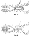
- an exhaust system 1 comprises two separate exhaust lines 2 and 3.
- the exhaust system 1 serves to dissipate the exhaust gases in an internal combustion engine 4, which may be arranged in particular in a motor vehicle.
- the two exhaust gas lines 2, 3 are assigned to different cylinders 5 of the internal combustion engine 4. In the example, a six-cylinder engine is shown without limiting the generality.
- the two exhaust gas lines 2, 3 are each assigned to a group of cylinders 5, which are selected such that the cylinders 5 of a cylinder group and the cylinders 5 of the other cylinder group have their working strokes each alternating.
- the cylinder groups can be selected so that parallel-acting cylinders are each arranged in different cylinder groups. This is especially true for larger engines, such as V-eight or V-twelve engines.
- the exhaust system 1 also has a first switchable sound transmission device 7, which is designed so that it can couple the two exhaust gas lines 2, 3 for the transmission of airborne sound.
- the exhaust system 1 according to the invention comprises a second switchable sound transmission device 8, which is designed such that it the two exhaust gas lines 2, 3 downstream of the first Sound transmission device 7 can couple to each other for the transmission of airborne sound.
- a control device 9 For switching or for actuating the two sound transmission devices 7, a control device 9 is provided. This is designed so that it can control the two sound transmission devices 7, 8 as a function of at least one operating parameter of the internal combustion engine 4 for activating and deactivating.
- the activated state a sound transmission between the two exhaust lines 2, 3 by the respective sound transmission device 7, 8.
- the deactivated state the sound transmission between the two exhaust lines 2, 3 is omitted by the respective sound transmission device 7, 8.
- the control device 9 is also according to the invention configured so that it can control the two sound transmission devices 7, 8 in response to the at least one operating parameter of the internal combustion engine 4 for the realization of at least three different switching states. In a first switching state, both sound transmission devices 7, 8 are deactivated.
- the control device 9 controls the sound transmission devices 7, 8 for realizing the second switching state such that the upstream first sound transmission device 7 is deactivated and that the downstream second sound transmission device 8 is activated.
- the control device 9 preferably uses a rotational speed of the internal combustion engine 4 in order to actuate the sound transmission devices 7, 8 as a function of the rotational speed.
- control device 9 is configured so that it divides the speed range of the internal combustion engine 4 in total into three speed ranges. In a lower speed range, the control device 9 actuates the sound transmission devices 7, 8 for setting the first switching state. In a medium speed range, the control device 9 adjusts the second switching state at the sound transmission devices 7, 8. In an upper speed range, the control device 9 then realizes the third switching state.
- the corresponding speed information is received by the control device 9, e.g. from an engine control unit, not shown here.
- the control device 9 can be integrated into the hardware of such an engine control unit or implemented in software.
- the lower speed range may include speeds up to 1,500 RPM, while the medium speed range may include speeds from about 1,500 RPM to about 2,500 RPM.
- the upper speed range can then have speeds from 2,500 rpm.
- each exhaust line 2 includes a muffler 12.
- These mufflers 12 may in particular So-called rear muffler act whose outlet leads to the tailpipe 13 of the respective exhaust line 2, 3.
- each one of the exhaust lines 2, 3 associated mufflers 12 may in principle also be provided a common muffler, which is then assigned to both exhaust lines 2, 3.
- Fig. 2 In principle, it is possible to equip the exhaust system 1 with at least one middle silencer 14, which in particular can be assigned jointly to both exhaust lines 2, 3. Depending on the application and depending on the design of the exhaust system 1, it is by the use of the two sound transmission devices 7, 8 according to Fig. 1 possible to dispense with such a middle silencer 14 and yet to ensure adequate sound attenuation.
- the first sound transmission device 7 at the two exhaust gas lines 2, 3 downstream the catalysts 10 are arranged. Furthermore, the first sound transmission device 7 is located upstream of the silencer 12. The second sound transmission device 8 is arranged on both exhaust gas lines 2, 3 upstream of the two silencers 12. In addition, the second sound transmission device 8 is located downstream of the first sound transmission device 7 and thus downstream of the catalysts 10.
- the respective exhaust line 2, 3 upstream of the second sound transmission device 8 no further muffler.
- other exhaust gas treatment devices in the respective exhaust gas line 2, 3, in particular also downstream of the first sound transmission device 7 may be arranged upstream of the second sound transmission device 8, such as a particulate filter or an SCR catalyst or a Denox catalyst, however, none is designed exclusively as a muffler Component more available. As a result, the pressure loss in the respective exhaust line 2, 3 can be reduced.
- the two exhaust gas strands 2, 3 can run parallel to one another in a middle region 15.
- This middle area extends in the installed state in a tunnel, which is located on the underbody of the respective vehicle.
- the first sound transmission device 7 is arranged on the respective exhaust gas line 2, 3 in this central region 15, which extends in the tunnel.
- a positioning can be selected in which it is located in the middle region 15 running in the tunnel.
- the first sound transmission device 7 is preferably arranged in the respective exhaust gas line 2, 3 in a region which, relative to a flow path leading from the internal combustion engine 4 to the respective muffler 12, is less than or equal to 50% of this flow path.
- the first sound transmission device 7 may be positioned at about 30% to 50% or at about 40% to 50% or at about 50% of this flow path.
- this is in a range greater than or equal to 50% of said flow path.
- the second sound transmission device 8 is in a range of about 50% to 100% or from about 70% to 100% or from about 80% to 100% of the flow path. It has been shown that an embodiment is particularly advantageous if a flow path between the two sound transmission devices 7, 8 within the respective exhaust line 2, 3 is at least 50 cm.
- the respective sound transmission device 7 may have a connecting pipe 16 or 17 which connects the two exhaust gas strands 2, 3 communicating with each other. Furthermore, the respective sound transmission device 7 each have an actuator 18 and 19, z. As a slider or a flap or aperture, which designed so is that so that the respective connecting pipe 16, 17 can be opened and locked. Furthermore, an actuator 20 or 21 is here in each case still indicated, which serves to drive the respective actuator 18, 19 and which can be actuated or controlled by means of the control device 9.
- the respective sound transmission device 7, 8 configured so that only two switching states are adjustable to it, namely an active state with maximum sound transmission or maximum open cross section in the respective connecting pipe 16, 17 and an inactive state with no or minimal sound transmission or
- at least one of the sound transmission devices 7, 8 can realize at least one intermediate state in which the sound transmission between the exhaust gas strands 2, 3 is only partially activated or partially activated is only partially deactivated, so that in particular the flow cross-section in the respective connecting pipe 16, 17 is only partially opened or only partially blocked.
- the exhaust system 1 operates as follows:
- both sound transmission devices 7, 8 are deactivated.
- the exhaust gases of the two cylinder banks 6 are thus removed separately, without resulting in an acoustic coupling between the two exhaust gas lines 2, 3.
- This can be done also avoid interactions between the acoustic coupling and gas exchange processes. Such interactions can occur in the presence of an acoustic coupling, especially at low speeds, since sound waves are also pressure pulsations, which can also propagate upstream and thereby adversely affect charge exchange operations.
- the middle speed range ie above 1,500 rpm and below 2,500 rpm, the second sound transmission device 8 is activated.
- the first sound transmission device 7 is activated, whereby additional torque is provided.
- the common rear muffler or the two separate muffler 12 and possibly the center muffler 14 can be realized for the respective speed range effective sound attenuation.
Landscapes
- Engineering & Computer Science (AREA)
- Chemical & Material Sciences (AREA)
- Combustion & Propulsion (AREA)
- Mechanical Engineering (AREA)
- General Engineering & Computer Science (AREA)
- Exhaust Silencers (AREA)
Abstract
Description
Die vorliegende Erfindung betrifft eine Abgasanlage für eine Brennkraftmaschine, insbesondere in einem Kraftfahrzeug, mit den Merkmalen des Oberbegriffs des Anspruchs 1.The present invention relates to an exhaust system for an internal combustion engine, in particular in a motor vehicle, having the features of the preamble of
Bei Personenkraftwagen mit leistungsstarken Verbrennungsmotoren, die bevorzugt als V-Motoren ausgestaltet sind, werden die Abgase häufig aus den beiden Zylinderbänken über zwei Krümmer in zwei Abgassträngen bis zu einem gemeinsamen Endschalldämpfer oder zu zwei separaten Endschalldämpfern geführt. Die beiden Abgasstränge verlaufen dabei im Fahrzeug am Unterboden in einem Tunnel, der nach oben und zur Seite hin regelmäßig Hitzeschutzschilde aufweist. Nach unten stellt die Unterbodenfreiheit eine gedachte Grenze des Tunnels dar. Des Weiteren ist aus akustischen Gründen häufig ein Mittelschalldämpfer zu finden, der im mittleren Bereich der Anlage angeordnet werden muss. Hierbei kann jedem Abgasstrang ein separater Mittelschalldämpfer zugeordnet werden. Ebenso kann beiden Abgassträngen ein gemeinsamer Mittelschalldämpfer zugeordnet werden. Jedenfalls muss der jeweilige Mittelschalldämpfer ebenfalls im Tunnel untergebracht werden, was regelmäßig zu Bauraumproblemen führt, da der jeweilige Mittelschalldämpfer ein bestimmtes Mindestvolumen haben muss, um seine akustische Funktion erfüllen zu können.In passenger cars with high-performance internal combustion engines, which are preferably designed as V-engines, the exhaust gases are often fed from the two cylinder banks via two manifolds in two exhaust lines to a common muffler or two separate mufflers. The two exhaust strands run in the vehicle on the underbody in a tunnel which regularly has heat shields upwards and to the side. Down below, the underfloor clearance is an imaginary border of the tunnel dar. Furthermore, for acoustic reasons often find a center silencer, which must be located in the middle of the system. In this case, each exhaust tract a separate center muffler can be assigned. Likewise, both exhaust strands can be assigned a common middle silencer. Anyway, the respective middle silencer must also be accommodated in the tunnel, which regularly leads to space problems, since the respective Middle silencer must have a certain minimum volume in order to fulfill its acoustic function.
Aus der
Aus der
Die bekannte Abgasanlage wird zweckmäßig so betrieben, dass bei kleinen Drehzahlen die Schallübertragungseinrichtung aktiv ist. Schalldämpfer, die den Abgassträngen zugeordnet sind, sind akustisch auf Störfrequenzen ausgelegt, die bei niedrigen Drehzahlen auftreten. Bei höheren Drehzahlen wird die Schallübertragungseinrichtung deaktiviert, wodurch die effektiven Störfrequenzen aufgrund der gezielten Zuordnung der separaten Abgasstränge zu einzelnen Zylindern der Brennkraftmaschine halbiert wird. Somit kann für zwei Drehzahlbereiche, die über die Störfrequenzen zueinander in Beziehung stehen, eine effektive Schalldämpfung erreicht werden. Nachteilig ist dabei die Einschränkung der Dämpfungswirkung auf nur zwei Drehzahlbereiche. Des Weiteren kann die Aktivierung der Schallübertragungseinrichtung bei niedrigen Drehzahlen aufgrund von nachteiligen Auswirkungen auf den Ladungswechselvorgang bei den Zylindern der Brennkraftmaschine zu einer Reduzierung des verfügbaren Motordrehmoments führen.The known exhaust system is suitably operated so that at low speeds, the sound transmission device is active. Silencers associated with the exhaust lines are acoustically designed for noise frequencies that occur at low speeds. At higher speeds, the sound transmission device is deactivated, whereby the effective interference frequencies due to the targeted assignment of the separate exhaust lines to individual cylinders of the internal combustion engine is halved. Thus, for two speed ranges, which are related to each other via the interference frequencies, an effective sound attenuation can be achieved. The disadvantage here is the limitation of the damping effect on only two speed ranges. Furthermore, activation of the sound transmission device at low speeds may result in a reduction in the available engine torque due to adverse effects on the charge cycle of the cylinders of the internal combustion engine.
Hier setzt die vorliegende Erfindung an. Die vorliegende Erfindung beschäftigt sich mit dem Problem, für eine Abgasanlage der eingangs genannten Art, eine verbesserte Ausführungsform anzugeben, die sich insbesondere dadurch auszeichnet, dass der erforderliche Bauraum reduziert ist.This is where the present invention begins. The present invention is concerned with the problem, for an exhaust system of the type mentioned, to provide an improved embodiment, which is characterized in particular by the fact that the required space is reduced.
Dieses Problem wird erfindungsgemäß durch den Gegenstand des unabhängigen Anspruchs gelöst. Vorteilhafte Ausführungsformen sind Gegenstand der abhängigen Ansprüche.This problem is solved according to the invention by the subject matter of the independent claim. Advantageous embodiments are the subject of the dependent claims.
Die Erfindung beruht auf dem allgemeinen Gedanken, auf einen Mittelschalldämpfer zu verzichten. Die mit dem Einbau eines Mittelschalldämpfers einhergehenden Bauraumprobleme lassen sich dadurch vermeiden. Ermöglicht wird dies dadurch, dass die beiden Abgasstränge mit zwei schaltbaren Schallübertragungseinrichtungen akustisch gekoppelt werden, die in der Abgasströmungsrichtung voneinander beabstandet angeordnet sind. Hierdurch kann eine erhöhte Variabilität für die einstellbaren Schaltzustände realisiert werden. Von erhöhtem Interesse sind dabei zumindest drei unterschiedliche Schaltzustände, nämlich ein erster Schaltzustand, bei dem beide Schallübertragungseinrichtungen deaktiviert sind, ein zweiter Schaltzustand, bei dem die eine Schallübertragungseinrichtung aktiviert ist, während die andere Schallübertragungseinrichtung deaktiviert ist und ein dritter Schaltzustand, bei dem beide Schallübertragungseinrichtungen aktiviert sind. Es hat sich gezeigt, dass die unterschiedlichen Schaltzustände signifikante Auswirkungen auf das Drehmoment der mit der Abgasanlage ausgestatteten Brennkraftmaschine ergeben. Insbesondere lässt sich im ersten Schaltzustand das Drehmoment deutlich steigern, wenn dieser niedrigen Drehzahlen der Brennkraftmaschine zugeordnet ist, also Betriebszuständen, in denen ein hohes Drehmoment besonders erwünscht ist. Ferner hat sich gezeigt, dass durch die drei unterschiedlichen Schaltzustände auch die Dämpfungswirkung der Abgasanlage besser an unterschiedliche Betriebszustände der Brennkraftmaschine adaptierbar ist. Bei entsprechender Auslegung und Positionierung der beiden Schallübertragungseinrichtungen kann nun die Dämpfungswirkung der Abgasanlage insgesamt soweit verbessert werden, dass erfindungsgemäß auf einen Mittelschalldämpfer verzichtet werden kann.The invention is based on the general idea to dispense with a middle silencer. The associated with the installation of a middle silencer space problems can be avoided. This is made possible by the fact that the two exhaust gas lines are acoustically coupled with two switchable sound transmission devices, which are arranged spaced apart in the exhaust gas flow direction. As a result, an increased variability for the adjustable switching states can be realized. Of increased interest are at least three different switching states, namely a first switching state in which both sound transmission devices are deactivated, a second switching state in which one sound transmission device is activated while the other sound transmission device is deactivated and a third switching state in which both sound transmission devices activated are. It has been found that the different switching states result in significant effects on the torque of the engine equipped with the exhaust system. In particular, in the first switching state, the torque can be significantly increased if this low rotational speed of the internal combustion engine is assigned, ie operating states in which a high torque is particularly desirable. Furthermore, it has been shown that the damping effect of the exhaust system can be better adapted to different operating states of the internal combustion engine by the three different switching states. With appropriate design and positioning of the two sound transmission devices can now be the extent of the damping effect of the exhaust system improved so far that according to the invention can be dispensed with a middle silencer.
Ferner werden die Schallübertragungseinrichtungen bei der erfindungsgemäßen Abgasanlage stromab von Katalysatoren angeordnet, die in beiden Abgassträngen vorgesehen sind.Furthermore, the sound transmission devices are arranged in the exhaust system according to the invention downstream of catalysts, which are provided in both exhaust lines.
Besonders vorteilhaft hat sich eine Ausführungsform herausgestellt, bei welcher im zweiten Betriebszustand die stromauf liegende erste Schallübertragungseinrichtung deaktiviert ist, während die stromab liegende zweite Schallübertragungseinrichtung aktiviert ist. Im zweiten Schaltzustand kann beispielsweise für mittlere Drehzahlen das Drehmoment erhöht werden.An embodiment has proven to be particularly advantageous in which the upstream first sound transmission device is deactivated in the second operating state, while the downstream second sound transmission device is activated. In the second switching state, for example, the torque can be increased for average speeds.
Zweckmäßig ordnet eine Steuereinrichtung die Schaltzustände unterschiedlichen Drehzahlbereichen zu. Dabei ist der erste Schaltzustand einem unteren Drehzahlbereich zugeordnet, während der zweite Schaltzustand einem mittleren Drehzahlbereich zugeordnet ist und der dritte Schaltzustand einem oberen Drehzahlbereich zugeordnet ist.Suitably, a control device assigns the switching states to different speed ranges. In this case, the first switching state is associated with a lower speed range, while the second switching state is associated with a medium speed range and the third switching state is associated with an upper speed range.
Weitere wichtige Merkmale und Vorteile der Erfindung ergeben sich aus den Unteransprüchen, aus den Zeichnungen und aus der zugehörigen Figurenbeschreibung anhand der Zeichnungen.Other important features and advantages of the invention will become apparent from the dependent claims, from the drawings and from the associated figure description with reference to the drawings.
Es versteht sich, dass die vorstehend genannten und die nachstehend noch zu erläuternden Merkmale nicht nur in der jeweils angegebenen Kombination, sondern auch in anderen Kombinationen oder in Alleinstellung verwendbar sind, ohne den Rahmen der vorliegenden Erfindung zu verlassen.It is understood that the features mentioned above and those yet to be explained not only in the each combination specified, but also in other combinations or alone, without departing from the scope of the present invention.
Bevorzugte Ausführungsbeispiele der Erfindung sind in den Zeichnungen dargestellt und werden in der nachfolgenden Beschreibung näher erläutert, wobei sich gleiche Bezugszeichen auf gleiche oder ähnliche oder funktional gleiche Bauteile beziehen.Preferred embodiments of the invention are illustrated in the drawings and will be described in more detail in the following description, wherein like reference numerals refer to the same or similar or functionally identical components.
Es zeigen, jeweils schematisch,
- Fig. 1
- eine stark vereinfachte, schaltplanartige Prinzip- darstellung einer erfindungsgemäßen Abgasanlage,
- Fig. 2
- eine Ansicht wie in
Fig. 1 , jedoch bei einer gat- tungsgemäßen Abgasanlage.
- Fig. 1
- a greatly simplified, schematic diagram of a schematic representation of an exhaust system according to the invention,
- Fig. 2
- a view like in
Fig. 1 , but in a generic exhaust system.
Entsprechend den
Ebenso können die Zylindergruppen so gewählt werden, dass parallel arbeitende Zylinder jeweils in verschiedenen Zylindergruppen angeordnet sind. Dies gilt insbesondere für gröβere Motoren, wie V-Acht- oder V-Zwölf-Motoren.Likewise, the cylinder groups can be selected so that parallel-acting cylinders are each arranged in different cylinder groups. This is especially true for larger engines, such as V-eight or V-twelve engines.
Die Abgasanlage 1 weist außerdem eine erste schaltbare Schallübertragungseinrichtung 7 auf, die so ausgestaltet ist, dass sie die beiden Abgasstränge 2, 3 zur Übertragung von Luftschall miteinander koppeln kann. Außerdem umfasst die erfindungsgemäße Abgasanlage 1 eine zweite schaltbare Schallübertragungseinrichtung 8, die so ausgestaltet ist, dass sie die beiden Abgasstränge 2, 3 stromab der ersten Schallübertragungseinrichtung 7 zur Übertragung von Luftschall miteinander koppeln kann.The
Zum Schalten bzw. zum Betätigen der beiden Schallübertragungseinrichtungen 7 ist eine Steuereinrichtung 9 vorgesehen. Diese ist so ausgestaltet, dass sie die beiden Schallübertragungseinrichtungen 7, 8 in Abhängigkeit zumindest eines Betriebsparameters der Brennkraftmaschine 4 zum Aktivieren und Deaktivieren ansteuern kann. Im jeweiligen aktivierten Zustand erfolgt eine Schallübertragung zwischen den beiden Abgassträngen 2, 3 durch die jeweilige Schallübertragungseinrichtung 7, 8. Im deaktivierten Zustand unterbleibt jedoch die Schallübertragung zwischen den beiden Abgassträngen 2, 3 durch die jeweilige Schallübertragungseinrichtung 7, 8. Die Steuereinrichtung 9 ist erfindungsgemäß außerdem so ausgestaltet, dass sie die beiden Schallübertragungseinrichtungen 7, 8 in Abhängigkeit des wenigstens einen Betriebsparameters der Brennkraftmaschine 4 zur Realisierung von wenigstens drei unterschiedlichen Schaltzuständen ansteuern kann. In einem ersten Schaltzustand sind beide Schallübertragungseinrichtungen 7, 8 deaktiviert. In einem zweiten Schaltzustand ist eine der Schallübertragungseinrichtungen 7, 8 aktiviert, während gleichzeitig die jeweils andere Schallübertragungseinrichtung 7, 8 deaktiviert ist. In einem dritten Schaltzustand sind dann beide Schallübertragungseinrichtungen 7, 8 aktiviert. Vorzugsweise steuert die Steuereinrichtung 9 die Schallübertragungseinrichtungen 7, 8 zur Realisierung des zweiten Schaltzustands so an, dass die stromauf liegende erste Schallübertragungseinrichtung 7 deaktiviert ist und dass die stromab liegende zweite Schallübertragungseinrichtung 8 aktiviert ist. Als Betriebsparameter der Brennkraftmaschine 4 verwendet die Steuereinrichtung 9 bevorzugt eine Drehzahl der Brennkraftmaschine 4, um die Schallübertragungseinrichtungen 7, 8 in Abhängigkeit der Drehzahl zu betätigen.For switching or for actuating the two
Besonders vorteilhaft ist dabei eine Ausführungsform, bei welcher die Steuereinrichtung 9 so ausgestaltet ist, dass sie den Drehzahlbereich der Brennkraftmaschine 4 insgesamt in drei Drehzahlbereiche unterteilt. In einem unteren Drehzahlbereich betätigt die Steuereinrichtung 9 die Schallübertragungseinrichtungen 7, 8 zum Einstellen des ersten Schaltzustands. In einem mittleren Drehzahlbereich stellt die Steuereinrichtung 9 an den Schallübertragungseinrichtungen 7, 8 den zweiten Schaltzustand ein. In einem oberen Drehzahlbereich realisiert die Steuereinrichtung 9 dann den dritten Schaltzustand. Die entsprechende Drehzahlinformation erhält die Steuereinrichtung 9 z.B. von einem hier nicht gezeigten Motorsteuergerät. Insbesondere kann die Steuereinrichtung 9 hardwaremäßig in ein solches Motorsteuergerät integriert oder softwaremäßig implementiert sein.Particularly advantageous is an embodiment in which the
Beispielsweise kann für einen Sechs-Zylinder-Motor der untere Drehzahlbereich Drehzahlen bis 1.500 U/min umfassen, während der mittlere Drehzahlbereich Drehzahlen von etwa 1.500 U/min bis etwa 2.500 U/min umfassen kann. Der obere Drehzahlbereich kann dann Drehzahlen ab 2.500 U/min aufweisen.For example, for a six-cylinder engine, the lower speed range may include speeds up to 1,500 RPM, while the medium speed range may include speeds from about 1,500 RPM to about 2,500 RPM. The upper speed range can then have speeds from 2,500 rpm.
Entsprechend den
Entsprechend
Entsprechend den
Bei der in
Gemäß den
Die erste Schallübertragungseinrichtung 7 ist im jeweiligen Abgasstrang 2, 3 vorzugsweise in einem Bereich angeordnet, der bezogen auf einen von der Brennkraftmaschine 4 zum jeweiligen Schalldämpfer 12 führenden Strömungsweg kleiner oder gleich 50 % dieses Strömungswegs beträgt. Bevorzugt kann die erste Schallübertragungseinrichtung 7 bei etwa 30 % bis 50 % oder bei etwa 40 % bis 50 % oder bei etwa 50 % dieses Strömungswegs positioniert sein. Im Unterschied dazu gilt für die Positionierung der zweiten Schallübertragungseinrichtung 8, dass sich diese in einem Bereich größer oder gleich 50 % des genannten Strömungswegs befindet. Bevorzugt befindet sich die zweite Schallübertragungseinrichtung 8 in einem Bereich von etwa 50 % bis 100 % oder von etwa 70 % bis 100 % oder von etwa 80 % bis 100 % des Strömungswegs. Es hat sich gezeigt, dass eine Ausführungsform besonders vorteilhaft ist, wenn ein Strömungsweg zwischen den beiden Schallübertragungseinrichtungen 7, 8 innerhalb des jeweiligen Abgasstrangs 2, 3 zumindest 50 cm beträgt.The first
Die jeweilige Schallübertragungseinrichtung 7 kann ein Verbindungsrohr 16 bzw. 17 aufweisen, das jeweils die beiden Abgasstränge 2, 3 miteinander kommunizierend verbindet. Ferner kann die jeweilige Schallübertragungseinrichtung 7 jeweils ein Stellglied 18 bzw. 19 aufweisen, z. B. einen Schieber oder eine Klappe oder eine Blende, das so ausgestaltet ist, dass damit das jeweilige Verbindungsrohr 16, 17 geöffnet und gesperrt werden kann. Ferner ist hier jeweils noch ein Stellantrieb 20 bzw. 21 angedeutet, der zum Antreiben des jeweiligen Stellglieds 18, 19 dient und der mit Hilfe der Steuereinrichtung 9 betätigbar bzw. ansteuerbar ist. Im einfachsten Fall ist die jeweilige Schallübertragungseinrichtung 7, 8 so ausgestaltet, dass an ihr jeweils nur zwei Schaltzustände einstellbar sind, nämlich ein Aktivzustand mit maximaler Schallübertragung bzw. maximal geöffnetem Querschnitt im jeweiligen Verbindungsrohr 16, 17 und ein Inaktivzustand mit keiner oder minimaler Schallübertragung bzw. mit gesperrtem oder minimal geöffnetem Querschnitt im jeweiligen Verbindungsrohr 16, 17. Grundsätzlich sind jedoch auch Ausführungsformen denkbar, bei denen zumindest eine der Schallübertragungseinrichtungen 7, 8 wenigstens einen Zwischenzustand realisieren kann, bei dem die Schallübertragung zwischen den Abgassträngen 2, 3 nur zum Teil aktiviert bzw. nur zum Teil deaktiviert ist, so dass insbesondere der Strömungsquerschnitt im jeweiligen Verbindungsrohr 16, 17 nur zum Teil geöffnet bzw. nur zum Teil gesperrt ist.The respective
Bei einem Betrieb der Brennkraftmaschine 4 im unteren Drehzahlbereich, also beispielsweise unter 1.500 U/min sind beide Schallübertragungseinrichtungen 7, 8 deaktiviert. Die Abgase der beiden Zylinderbänke 6 werden somit getrennt abgeführt, ohne dass es zu einer akustischen Kopplung zwischen den beiden Abgassträngen 2, 3 kommt. Hierdurch lassen sich auch Wechselwirkungen zwischen der akustischen Kopplung und Ladungswechselvorgängen vermeiden. Derartige Wechselwirkungen können bei Vorliegen einer akustischen Kopplung insbesondere bei niedrigen Drehzahlen auftreten, da Schallwellen auch Druckpulsationen sind, die sich auch stromauf ausbreiten können und dadurch Ladungswechselvorgänge nachteilig beeinflussen können. Im mittleren Drehzahlbereich, also oberhalb 1.500 U/min und unterhalb 2.500 U/min wird die zweite Schallübertragungseinrichtung 8 aktiviert. Hierdurch kann für den mittleren Drehzahlbereich zusätzliches Drehmoment gewonnen werden. Im oberen Drehzahlbereich, also oberhalb 2.500 U/min wird auch die erste Schallübertragungseinrichtung 7 aktiviert, wodurch zusätzliches Drehmoment bereitgestellt wird. Durch eine entsprechende Abstimmung des gemeinsamen Endschalldämpfers oder der beiden separaten Endschalldämpfer 12 sowie ggf. des Mittelschalldämpfers 14 kann für den jeweiligen Drehzahlbereich eine effektive Schalldämpfung realisiert werden.During operation of the internal combustion engine 4 in the lower speed range, that is, for example, below 1500 rpm, both
Claims (12)
- An exhaust system for a combustion engine (4), particularly in a motor vehicle,- with two separate exhaust gas lines (2, 3) for discharging exhaust gases of a combustion engine (4), each of which having a catalytic converter (10),- with a switchable first sound transmission device (7), which couples the two exhaust lines (2, 3) for the transmission of airborne sound with each other,- with a control device (9) for the activation and deactivation of the first sound transmission device (7) as a function of at least one operating parameter of the combustion engine (4),- wherein a second sound transmission device (8) switchable with the control device (9) is provided, which couples the two exhaust lines (2, 3) downstream of the first sound transmission device (7) for the transmission of airborne sound with each other,- wherein the control device (9) is designed so that said control device as a function of the at least one operating parameter of the combustion engine (4) makes possible at least three switching states for the two sound transmission devices (7, 8), namely- a first switching state, with which both sound transmission devices (7, 8) are deactivated,- a second switching state, with which the one sound transmission device (7, 8) is activated, while the other sound transmission device (7, 8) is deactivated,- a third switching state, with which both sound transmission devices (7, 8) are activated,characterized- in that the first sound transmission device (7) is arranged on both exhaust lines (2, 3) downstream of the respective catalytic converter (10),- in that no middle silencer is provided.
- The exhaust system according to Claim 1,
characterized in that
in the second switching state the first sound transmission device (7) located upstream is deactivated, while the second sound transmission device (8) located downstream is activated. - The exhaust system according to Claim 1 or 2,
characterized in that
the control device (9) for the switching of the sound transmission devices (7, 8) uses a rotational speed of the combustion engine (4) as operating parameter. - The exhaust system according to any one of the Claims 1 to 3,
characterized in that
the control device (9) is designed so- that in a lower rotational speed range it establishes the first switching state,- that in a middle rotational speed range it establishes the second switching state,- that in an upper rotational speed range it establishes the third switching state. - The exhaust system according to any one of the Claims 1 to 4,
characterized- in that two exhaust lines (2, 3) are each assigned to a cylinder group of the combustion engine (4), wherein the cylinders (5) of the one cylinder group and the cylinders (5) of the other cylinder group perform their working strokes in alternation or synchronously, and/or- in that the two exhaust lines (2, 3) are each assigned to a cylinder bank (6) of a combustion engine (4) designed as V-engine. - The exhaust system according to any one of the Claims 1 to 5,
characterized in that
the second sound transmission device (8) is arranged on both exhaust lines (2, 3) upstream in each case of a separate or a joint rear silencer (12). - The exhaust system according to any one of the Claims 1 to 6,
characterized in that
the respective exhaust line (2, 3) upstream of the second sound transmission device (8) does not contain a silencer. - The exhaust system according to any one of the Claims 1 to 7,
characterized in that
the first sound transmission device (7) is arranged in the respective exhaust line (2, 3) in a region smaller than or approximately equal to 50% or of approximately 30% to 50% or of approximately 40% to 50% of a flow path between the combustion engine (4) and a silencer (12) assigned to the respective exhaust line (2, 3). - The exhaust system according to any one of the Claims 1 to 8,
characterized in that
the second sound transmission device (8) in the respective exhaust line (2, 3) is arranged in a region that is greater or equal to 50% or of approximately 50% or of approximately 70% to 100% or of approximately 80% to 100% of a flow path between the combustion engine (4) and a silencer (12) assigned to the respective exhaust line (2, 3). - The exhaust system according to any one of the Claims 1 to 9,
characterized in that
the first sound transmission device (7) and/or the second sound transmission device (8) is/are arranged on the two exhaust lines (2, 3) in a region (15) in which the two exhaust lines (2, 3) in the assembled state run in a tunnel of the vehicle. - The exhaust system according to any one of the Claims 1 to 10,
characterized in that
the flow path between the two sound transmission devices (7, 8) in the respective exhaust line (2, 3) amounts to at least 50 cm. - The exhaust system according to any one of the Claims 1 to 11,
characterized- in that the respective sound transmission device (7, 8)comprises a connecting pipe (16, 17), which interconnects the two exhaust lines (2, 3) in a communicating manner, and/or- in that the respective sound transmission device (7, 8) comprises an actuator (18, 19) for opening and blocking the respective connecting pipe (16, 17).
Applications Claiming Priority (1)
| Application Number | Priority Date | Filing Date | Title |
|---|---|---|---|
| DE102007026812A DE102007026812A1 (en) | 2007-06-06 | 2007-06-06 | exhaust system |
Publications (2)
| Publication Number | Publication Date |
|---|---|
| EP2000643A1 EP2000643A1 (en) | 2008-12-10 |
| EP2000643B1 true EP2000643B1 (en) | 2011-07-27 |
Family
ID=39735108
Family Applications (1)
| Application Number | Title | Priority Date | Filing Date |
|---|---|---|---|
| EP08157029A Not-in-force EP2000643B1 (en) | 2007-06-06 | 2008-05-28 | Exhaust system |
Country Status (5)
| Country | Link |
|---|---|
| US (1) | US7703574B2 (en) |
| EP (1) | EP2000643B1 (en) |
| AT (1) | ATE518051T1 (en) |
| DE (1) | DE102007026812A1 (en) |
| ES (1) | ES2370452T3 (en) |
Families Citing this family (33)
| Publication number | Priority date | Publication date | Assignee | Title |
|---|---|---|---|---|
| US8365522B2 (en) * | 2008-08-21 | 2013-02-05 | Emcon Technologies Llc | Dual exhaust system with independent valve control |
| DE102009032214B4 (en) | 2009-07-06 | 2023-10-19 | Dr. Ing. H.C. F. Porsche Aktiengesellschaft | Exhaust system of an internal combustion engine |
| DE102009032215A1 (en) | 2009-07-06 | 2011-01-27 | Dr. Ing. H.C. F. Porsche Aktiengesellschaft | Exhaust system of an internal combustion engine |
| DE102009032213B4 (en) | 2009-07-06 | 2024-05-16 | Dr. Ing. H.C. F. Porsche Aktiengesellschaft | Exhaust system of an internal combustion engine |
| DE102010008277B4 (en) | 2010-02-17 | 2023-10-12 | Dr. Ing. H.C. F. Porsche Aktiengesellschaft | Exhaust system of an internal combustion engine |
| DE102010017487A1 (en) | 2010-06-21 | 2011-12-22 | Dr. Ing. H.C. F. Porsche Aktiengesellschaft | Exhaust system for motor vehicle, has one or more exhaust lines, where exhaust particulate filter has filter disk mounted in radial or axial manner |
| KR101195148B1 (en) | 2010-07-29 | 2012-10-29 | 삼성중공업 주식회사 | System for reducing hazardous substances in exhaust gas and vehicle including the same |
| US8309045B2 (en) | 2011-02-11 | 2012-11-13 | General Electric Company | System and method for controlling emissions in a combustion system |
| DE102011051690B4 (en) * | 2011-07-08 | 2023-06-29 | Dr. Ing. H.C. F. Porsche Aktiengesellschaft | Control device of a motor vehicle with a noise transmission system and an exhaust system |
| JP5895577B2 (en) * | 2012-02-14 | 2016-03-30 | スズキ株式会社 | Engine exhaust control device |
| EP2657494A1 (en) * | 2012-04-23 | 2013-10-30 | Ford Global Technologies, LLC | Externally ignited combustion engine with wall section separating at least two cylinders |
| DE102012112433A1 (en) * | 2012-12-17 | 2014-06-18 | Dr. Ing. H.C. F. Porsche Aktiengesellschaft | Exhaust system for an internal combustion engine |
| US9067176B2 (en) | 2013-03-15 | 2015-06-30 | Honeywell International, Inc. | Specialized ammonia injection grid with the dual purpose of suppressing noise |
| KR101511541B1 (en) * | 2013-11-15 | 2015-04-13 | 현대자동차주식회사 | Structure of dual exhaust system for cda engine |
| DE102014011618B4 (en) * | 2014-08-01 | 2016-11-10 | Audi Ag | Exhaust system for an internal combustion engine |
| US10443479B2 (en) | 2014-10-30 | 2019-10-15 | Roush Enterprises, Inc. | Exhaust control system |
| JP5945018B1 (en) * | 2015-01-30 | 2016-07-05 | 本田技研工業株式会社 | Exhaust muffler |
| DE102015211460A1 (en) * | 2015-06-22 | 2016-12-22 | Bayerische Motoren Werke Aktiengesellschaft | exhaust system |
| DE102015011175B4 (en) * | 2015-08-27 | 2021-01-14 | Audi Ag | Exhaust system for an internal combustion engine |
| PL3141720T3 (en) * | 2015-09-10 | 2019-06-28 | Akrapovic D.D. | Exhaust system for an internal combustion automotive engine |
| JP6551132B2 (en) * | 2015-10-13 | 2019-07-31 | スズキ株式会社 | Engine exhaust control device |
| WO2017079156A1 (en) | 2015-11-02 | 2017-05-11 | Roush Enterprises, Inc. | Muffler with selected exhaust pathways |
| KR101762280B1 (en) * | 2016-03-28 | 2017-07-28 | 현대자동차주식회사 | Structure of central-through type active control valve |
| US20170298802A1 (en) * | 2016-04-14 | 2017-10-19 | Hyundai Motor Company | Structure of exhaust pipe |
| US10287937B2 (en) * | 2016-06-17 | 2019-05-14 | Ford Global Technologies, Llc | Exhaust system for an engine |
| KR101762281B1 (en) * | 2016-06-20 | 2017-07-31 | 현대자동차주식회사 | Variable Confluence portion Structure of Exhaust Pipe |
| US20180223709A1 (en) * | 2017-02-06 | 2018-08-09 | GM Global Technology Operations LLC | Function based continuous exhaust valve control |
| US10837333B2 (en) * | 2017-12-28 | 2020-11-17 | Ford Global Technologies, Llc | Exhaust system having tunable exhaust sound |
| US10358956B1 (en) | 2018-07-09 | 2019-07-23 | Faurecia Emissions Control Technologies, Usa, Llc | Exhaust valve and active noise control for compact exhaust system |
| KR102096998B1 (en) * | 2018-08-31 | 2020-04-03 | 정지연 | Exhaust gas exhaust device |
| US11401851B1 (en) * | 2019-06-18 | 2022-08-02 | Tilahun Anshu | Vehicular exhaust system |
| KR102768237B1 (en) * | 2020-07-14 | 2025-02-18 | 쩌지앙 길리 홀딩 그룹 씨오., 엘티디. | Exhaust noise devices, systems, vehicles and methods |
| US11598236B2 (en) * | 2020-09-28 | 2023-03-07 | Ford Global Technologies, Llc | Exhaust system |
Family Cites Families (27)
| Publication number | Priority date | Publication date | Assignee | Title |
|---|---|---|---|---|
| US2180843A (en) * | 1933-03-29 | 1939-11-21 | Sperry Gyroscope Co Inc | Noise reducing means for cabin aircraft |
| US3653212A (en) * | 1970-10-30 | 1972-04-04 | Gen Motors Corp | Exhaust emission control system |
| DE2322057A1 (en) * | 1973-05-02 | 1974-11-21 | Porsche Ag | DEVICE FOR CATALYTIC AFTER-BURNING OF EXHAUST GASES OF A MULTICYLINDRICAL COMBUSTION MACHINE |
| JPS58178820A (en) * | 1982-04-14 | 1983-10-19 | Yamaha Motor Co Ltd | Exhaust device for motorcycle |
| US4527392A (en) * | 1983-04-20 | 1985-07-09 | Hino Jidosha Kogyo Kabushiki Kaisha | Bypass valve actuator for inertia supercharging in multicylinder engines |
| JPS60247006A (en) * | 1984-05-22 | 1985-12-06 | Yoichi Yamazaki | Exhaust device for multicylinder engine |
| GB2161215A (en) * | 1984-07-05 | 1986-01-08 | Shelburne Inc | Exhaust systems for internal combustion engines |
| JPH0629548B2 (en) * | 1985-03-18 | 1994-04-20 | ヤマハ発動機株式会社 | Exhaust system for multi-cylinder engine |
| GB8516420D0 (en) * | 1985-06-28 | 1985-07-31 | Ontario Research Foundation | Diesel particulate traps |
| DE3740238A1 (en) * | 1986-12-04 | 1988-06-23 | Audi Ag | EXHAUST SYSTEM FOR AN INTERNAL COMBUSTION ENGINE WITH TWO CYLINDER BENCHES |
| JPH086576B2 (en) * | 1987-06-08 | 1996-01-24 | 日産自動車株式会社 | Exhaust system for multi-cylinder engine |
| JPH0544503Y2 (en) * | 1988-07-29 | 1993-11-11 | ||
| GB8923615D0 (en) * | 1989-10-19 | 1989-12-06 | Dewandre Co Ltd C | Exhaust system |
| JP3053823B2 (en) * | 1989-10-23 | 2000-06-19 | カルソニック株式会社 | Vehicle exhaust system control method |
| JP2586164B2 (en) * | 1990-02-03 | 1997-02-26 | トヨタ自動車株式会社 | Exhaust system of internal combustion engine |
| DE4106918B4 (en) | 1991-03-05 | 2006-11-09 | Bayerische Motoren Werke Ag | Multi-cylinder internal combustion engine with an inlet / outlet control with overlap of the timing and a multi-flow exhaust system |
| US5144799A (en) * | 1991-07-18 | 1992-09-08 | Barth Randolph S | Crossfire calibrated exhaust system |
| US5317112A (en) * | 1991-10-16 | 1994-05-31 | Hyundai Motor Company | Intake silencer of the variable type for use in motor vehicle |
| US5937640A (en) * | 1997-12-10 | 1999-08-17 | Ford Global Technologies, Inc. | Thermal management system for catalytic converters |
| DE19840096A1 (en) * | 1998-09-03 | 2000-03-09 | Porsche Ag | Exhaust system of a multi-cylinder internal combustion engine |
| US6141958A (en) * | 1998-12-31 | 2000-11-07 | Voss; Randy E. | Exhaust cooling system for vehicles |
| DE10104021B4 (en) * | 2001-01-31 | 2013-04-25 | Daimler Ag | exhaust system |
| DE20206155U1 (en) * | 2002-04-19 | 2002-08-01 | Audi Ag, 85057 Ingolstadt | Flap-controlled exhaust system to increase performance and torque |
| DE10231056A1 (en) * | 2002-07-10 | 2004-02-05 | J. Eberspächer GmbH & Co. KG | exhaust system |
| DE10236732A1 (en) * | 2002-08-09 | 2004-02-12 | Bayerische Motoren Werke Ag | Exhaust system for internal combustion engine with groups of cylinders comprises manifolds for each group which lead to connector linking them to several parallel exhaust pipes |
| DE10244021A1 (en) | 2002-09-21 | 2004-04-01 | J. Eberspächer GmbH & Co. KG | Exhaust system for an internal combustion engine |
| US7090048B2 (en) * | 2003-09-26 | 2006-08-15 | General Motors Corporation | Method and apparatus for exhaust sound attenuation on engines with cylinder deactivation |
-
2007
- 2007-06-06 DE DE102007026812A patent/DE102007026812A1/en not_active Withdrawn
-
2008
- 2008-05-28 AT AT08157029T patent/ATE518051T1/en active
- 2008-05-28 EP EP08157029A patent/EP2000643B1/en not_active Not-in-force
- 2008-05-28 ES ES08157029T patent/ES2370452T3/en active Active
- 2008-06-04 US US12/132,801 patent/US7703574B2/en active Active
Also Published As
| Publication number | Publication date |
|---|---|
| US20080302597A1 (en) | 2008-12-11 |
| EP2000643A1 (en) | 2008-12-10 |
| US7703574B2 (en) | 2010-04-27 |
| DE102007026812A1 (en) | 2008-12-11 |
| ES2370452T3 (en) | 2011-12-16 |
| ATE518051T1 (en) | 2011-08-15 |
Similar Documents
| Publication | Publication Date | Title |
|---|---|---|
| EP2000643B1 (en) | Exhaust system | |
| EP1380734B1 (en) | Exhaust system | |
| EP2531710B1 (en) | Internal combustion engine having cylinder deactivation | |
| EP3311009B1 (en) | Exhaust system | |
| EP1760279B1 (en) | Silencer for an exhaust system | |
| EP2183471B1 (en) | Exhaust-gas secondary treatment preceding a turbocharger | |
| DE102004046184B4 (en) | Method for exhaust noise attenuation in engines with cylinder deactivation | |
| EP2134942B1 (en) | Internal combustion engine | |
| EP2154356A1 (en) | Arrangement with a protected turbocharger in the exhaust gas recirculation line | |
| EP2122137B1 (en) | Internal combustion engine system | |
| EP1400666B1 (en) | Exhaust System for an Internal Combustion Engine | |
| WO2006007931A1 (en) | Arrangement for an internal combustion engine | |
| EP2427647A1 (en) | Internal combustion engine and associated operational method | |
| EP1798390B2 (en) | Engine exhaust apparatus | |
| DE102005055240A1 (en) | Exhaust gas after-treatment device for e.g. diesel engine, has after-treatment unit to retain and oxidize sooty particles from gas stream, and throttle valve arranged in auxiliary exhaust gas system for regulating proportion of stream | |
| DE10030490B4 (en) | Exhaust system for an internal combustion engine | |
| DE102007030250A1 (en) | Sound modification device, particularly exhaust silencer of motor vehicle, has detecting sound device arranged to detect sound wave with frequency spectrum | |
| DE102011055266A1 (en) | Double-flow exhaust system for combustion engine in motor car, has delay device designed to produce running time difference of exhaust gas when exhaust gas of engine flows between exhaust lines through system | |
| DE102018123536A1 (en) | Method and device for enabling a reduction in space in a vehicle exhaust system | |
| EP2105587B2 (en) | Exhaust gas installation | |
| DE10011920B4 (en) | Internal combustion engine of the Ottobau type | |
| DE102005031272A1 (en) | Exhaust system for four- or eight-cylinder internal combustion (IC) engine for motor vehicle, has cross joint, interposed between pre-tubes downstream of catalysts, having cross-sectional area variable as function of engine speed | |
| WO2009062590A1 (en) | Exhaust gas system and method for operating the same | |
| EP1486647A2 (en) | Method for regenerating a NOx storage catalyst in the exhaust system of a direct injection spark ignition gasoline engine | |
| DE102021134108A1 (en) | vehicle exhaust system |
Legal Events
| Date | Code | Title | Description |
|---|---|---|---|
| PUAI | Public reference made under article 153(3) epc to a published international application that has entered the european phase |
Free format text: ORIGINAL CODE: 0009012 |
|
| AK | Designated contracting states |
Kind code of ref document: A1 Designated state(s): AT BE BG CH CY CZ DE DK EE ES FI FR GB GR HR HU IE IS IT LI LT LU LV MC MT NL NO PL PT RO SE SI SK TR |
|
| AX | Request for extension of the european patent |
Extension state: AL BA MK RS |
|
| 17P | Request for examination filed |
Effective date: 20090610 |
|
| RIN1 | Information on inventor provided before grant (corrected) |
Inventor name: JESS, MARCO Inventor name: DER ANDERE ERFINDER HAT AUF SEINE NENNUNG VERZICHT |
|
| 17Q | First examination report despatched |
Effective date: 20090720 |
|
| AKX | Designation fees paid |
Designated state(s): AT BE BG CH CY CZ DE DK EE ES FI FR GB GR HR HU IE IS IT LI LT LU LV MC MT NL NO PL PT RO SE SI SK TR |
|
| RIN1 | Information on inventor provided before grant (corrected) |
Inventor name: JESS, MARCO Inventor name: KRUEGER, JAN, DR. |
|
| REG | Reference to a national code |
Ref country code: DE Ref legal event code: R079 Ref document number: 502008004332 Country of ref document: DE Free format text: PREVIOUS MAIN CLASS: F01N0007020000 Ipc: F01N0013020000 |
|
| GRAP | Despatch of communication of intention to grant a patent |
Free format text: ORIGINAL CODE: EPIDOSNIGR1 |
|
| RIC1 | Information provided on ipc code assigned before grant |
Ipc: F01N 13/02 20100101AFI20110221BHEP Ipc: F01N 13/08 20100101ALI20110221BHEP |
|
| RIN1 | Information on inventor provided before grant (corrected) |
Inventor name: JESS, MARCO Inventor name: KRUEGER, JAN |
|
| GRAS | Grant fee paid |
Free format text: ORIGINAL CODE: EPIDOSNIGR3 |
|
| GRAA | (expected) grant |
Free format text: ORIGINAL CODE: 0009210 |
|
| AK | Designated contracting states |
Kind code of ref document: B1 Designated state(s): AT BE BG CH CY CZ DE DK EE ES FI FR GB GR HR HU IE IS IT LI LT LU LV MC MT NL NO PL PT RO SE SI SK TR |
|
| REG | Reference to a national code |
Ref country code: GB Ref legal event code: FG4D Free format text: NOT ENGLISH |
|
| REG | Reference to a national code |
Ref country code: CH Ref legal event code: EP |
|
| REG | Reference to a national code |
Ref country code: DE Ref legal event code: R096 Ref document number: 502008004332 Country of ref document: DE Effective date: 20110922 |
|
| REG | Reference to a national code |
Ref country code: SE Ref legal event code: TRGR |
|
| REG | Reference to a national code |
Ref country code: NL Ref legal event code: VDEP Effective date: 20110727 |
|
| REG | Reference to a national code |
Ref country code: ES Ref legal event code: FG2A Ref document number: 2370452 Country of ref document: ES Kind code of ref document: T3 Effective date: 20111216 |
|
| PG25 | Lapsed in a contracting state [announced via postgrant information from national office to epo] |
Ref country code: LT Free format text: LAPSE BECAUSE OF FAILURE TO SUBMIT A TRANSLATION OF THE DESCRIPTION OR TO PAY THE FEE WITHIN THE PRESCRIBED TIME-LIMIT Effective date: 20110727 Ref country code: HR Free format text: LAPSE BECAUSE OF FAILURE TO SUBMIT A TRANSLATION OF THE DESCRIPTION OR TO PAY THE FEE WITHIN THE PRESCRIBED TIME-LIMIT Effective date: 20110727 Ref country code: NO Free format text: LAPSE BECAUSE OF FAILURE TO SUBMIT A TRANSLATION OF THE DESCRIPTION OR TO PAY THE FEE WITHIN THE PRESCRIBED TIME-LIMIT Effective date: 20111027 Ref country code: NL Free format text: LAPSE BECAUSE OF FAILURE TO SUBMIT A TRANSLATION OF THE DESCRIPTION OR TO PAY THE FEE WITHIN THE PRESCRIBED TIME-LIMIT Effective date: 20110727 Ref country code: PT Free format text: LAPSE BECAUSE OF FAILURE TO SUBMIT A TRANSLATION OF THE DESCRIPTION OR TO PAY THE FEE WITHIN THE PRESCRIBED TIME-LIMIT Effective date: 20111128 Ref country code: IS Free format text: LAPSE BECAUSE OF FAILURE TO SUBMIT A TRANSLATION OF THE DESCRIPTION OR TO PAY THE FEE WITHIN THE PRESCRIBED TIME-LIMIT Effective date: 20111127 Ref country code: FI Free format text: LAPSE BECAUSE OF FAILURE TO SUBMIT A TRANSLATION OF THE DESCRIPTION OR TO PAY THE FEE WITHIN THE PRESCRIBED TIME-LIMIT Effective date: 20110727 |
|
| PG25 | Lapsed in a contracting state [announced via postgrant information from national office to epo] |
Ref country code: LV Free format text: LAPSE BECAUSE OF FAILURE TO SUBMIT A TRANSLATION OF THE DESCRIPTION OR TO PAY THE FEE WITHIN THE PRESCRIBED TIME-LIMIT Effective date: 20110727 Ref country code: PL Free format text: LAPSE BECAUSE OF FAILURE TO SUBMIT A TRANSLATION OF THE DESCRIPTION OR TO PAY THE FEE WITHIN THE PRESCRIBED TIME-LIMIT Effective date: 20110727 Ref country code: GR Free format text: LAPSE BECAUSE OF FAILURE TO SUBMIT A TRANSLATION OF THE DESCRIPTION OR TO PAY THE FEE WITHIN THE PRESCRIBED TIME-LIMIT Effective date: 20111028 Ref country code: SI Free format text: LAPSE BECAUSE OF FAILURE TO SUBMIT A TRANSLATION OF THE DESCRIPTION OR TO PAY THE FEE WITHIN THE PRESCRIBED TIME-LIMIT Effective date: 20110727 Ref country code: CY Free format text: LAPSE BECAUSE OF FAILURE TO SUBMIT A TRANSLATION OF THE DESCRIPTION OR TO PAY THE FEE WITHIN THE PRESCRIBED TIME-LIMIT Effective date: 20110727 |
|
| REG | Reference to a national code |
Ref country code: IE Ref legal event code: FD4D |
|
| PG25 | Lapsed in a contracting state [announced via postgrant information from national office to epo] |
Ref country code: IE Free format text: LAPSE BECAUSE OF FAILURE TO SUBMIT A TRANSLATION OF THE DESCRIPTION OR TO PAY THE FEE WITHIN THE PRESCRIBED TIME-LIMIT Effective date: 20110727 Ref country code: CZ Free format text: LAPSE BECAUSE OF FAILURE TO SUBMIT A TRANSLATION OF THE DESCRIPTION OR TO PAY THE FEE WITHIN THE PRESCRIBED TIME-LIMIT Effective date: 20110727 Ref country code: SK Free format text: LAPSE BECAUSE OF FAILURE TO SUBMIT A TRANSLATION OF THE DESCRIPTION OR TO PAY THE FEE WITHIN THE PRESCRIBED TIME-LIMIT Effective date: 20110727 |
|
| PG25 | Lapsed in a contracting state [announced via postgrant information from national office to epo] |
Ref country code: EE Free format text: LAPSE BECAUSE OF FAILURE TO SUBMIT A TRANSLATION OF THE DESCRIPTION OR TO PAY THE FEE WITHIN THE PRESCRIBED TIME-LIMIT Effective date: 20110727 Ref country code: RO Free format text: LAPSE BECAUSE OF FAILURE TO SUBMIT A TRANSLATION OF THE DESCRIPTION OR TO PAY THE FEE WITHIN THE PRESCRIBED TIME-LIMIT Effective date: 20110727 |
|
| PLBE | No opposition filed within time limit |
Free format text: ORIGINAL CODE: 0009261 |
|
| STAA | Information on the status of an ep patent application or granted ep patent |
Free format text: STATUS: NO OPPOSITION FILED WITHIN TIME LIMIT |
|
| PG25 | Lapsed in a contracting state [announced via postgrant information from national office to epo] |
Ref country code: DK Free format text: LAPSE BECAUSE OF FAILURE TO SUBMIT A TRANSLATION OF THE DESCRIPTION OR TO PAY THE FEE WITHIN THE PRESCRIBED TIME-LIMIT Effective date: 20110727 |
|
| 26N | No opposition filed |
Effective date: 20120502 |
|
| REG | Reference to a national code |
Ref country code: DE Ref legal event code: R097 Ref document number: 502008004332 Country of ref document: DE Effective date: 20120502 |
|
| BERE | Be: lapsed |
Owner name: J. EBERSPACHER G.M.B.H. & CO. KG Effective date: 20120531 |
|
| PG25 | Lapsed in a contracting state [announced via postgrant information from national office to epo] |
Ref country code: MC Free format text: LAPSE BECAUSE OF NON-PAYMENT OF DUE FEES Effective date: 20120531 |
|
| REG | Reference to a national code |
Ref country code: CH Ref legal event code: PL |
|
| PG25 | Lapsed in a contracting state [announced via postgrant information from national office to epo] |
Ref country code: CH Free format text: LAPSE BECAUSE OF NON-PAYMENT OF DUE FEES Effective date: 20120531 Ref country code: LI Free format text: LAPSE BECAUSE OF NON-PAYMENT OF DUE FEES Effective date: 20120531 |
|
| PG25 | Lapsed in a contracting state [announced via postgrant information from national office to epo] |
Ref country code: BE Free format text: LAPSE BECAUSE OF NON-PAYMENT OF DUE FEES Effective date: 20120531 |
|
| PG25 | Lapsed in a contracting state [announced via postgrant information from national office to epo] |
Ref country code: BG Free format text: LAPSE BECAUSE OF FAILURE TO SUBMIT A TRANSLATION OF THE DESCRIPTION OR TO PAY THE FEE WITHIN THE PRESCRIBED TIME-LIMIT Effective date: 20111027 |
|
| PG25 | Lapsed in a contracting state [announced via postgrant information from national office to epo] |
Ref country code: MT Free format text: LAPSE BECAUSE OF FAILURE TO SUBMIT A TRANSLATION OF THE DESCRIPTION OR TO PAY THE FEE WITHIN THE PRESCRIBED TIME-LIMIT Effective date: 20110727 |
|
| REG | Reference to a national code |
Ref country code: DE Ref legal event code: R082 Ref document number: 502008004332 Country of ref document: DE Representative=s name: BRP RENAUD & PARTNER, DE |
|
| REG | Reference to a national code |
Ref country code: DE Ref legal event code: R082 Ref document number: 502008004332 Country of ref document: DE Representative=s name: BRP RENAUD UND PARTNER MBB RECHTSANWAELTE PATE, DE Effective date: 20131022 Ref country code: DE Ref legal event code: R082 Ref document number: 502008004332 Country of ref document: DE Representative=s name: BRP RENAUD UND PARTNER MBB, DE Effective date: 20131022 Ref country code: DE Ref legal event code: R081 Ref document number: 502008004332 Country of ref document: DE Owner name: EBERSPAECHER EXHAUST TECHNOLOGY GMBH & CO. KG, DE Free format text: FORMER OWNER: J. EBERSPAECHER GMBH & CO. KG, 73730 ESSLINGEN, DE Effective date: 20131022 Ref country code: DE Ref legal event code: R082 Ref document number: 502008004332 Country of ref document: DE Representative=s name: BRP RENAUD & PARTNER, DE Effective date: 20131022 |
|
| REG | Reference to a national code |
Ref country code: FR Ref legal event code: CD Owner name: EBERSPACHER CLIMATE CONTROL SYSTEMS GMBH & CO. KG Effective date: 20131129 |
|
| REG | Reference to a national code |
Ref country code: FR Ref legal event code: TP Owner name: EBERSPACHER EXHAUST TECHNOLOGY GMBH & CO. KG, DE Effective date: 20140204 |
|
| PG25 | Lapsed in a contracting state [announced via postgrant information from national office to epo] |
Ref country code: TR Free format text: LAPSE BECAUSE OF FAILURE TO SUBMIT A TRANSLATION OF THE DESCRIPTION OR TO PAY THE FEE WITHIN THE PRESCRIBED TIME-LIMIT Effective date: 20110727 |
|
| PG25 | Lapsed in a contracting state [announced via postgrant information from national office to epo] |
Ref country code: LU Free format text: LAPSE BECAUSE OF NON-PAYMENT OF DUE FEES Effective date: 20120528 |
|
| REG | Reference to a national code |
Ref country code: AT Ref legal event code: MM01 Ref document number: 518051 Country of ref document: AT Kind code of ref document: T Effective date: 20130528 |
|
| PG25 | Lapsed in a contracting state [announced via postgrant information from national office to epo] |
Ref country code: HU Free format text: LAPSE BECAUSE OF FAILURE TO SUBMIT A TRANSLATION OF THE DESCRIPTION OR TO PAY THE FEE WITHIN THE PRESCRIBED TIME-LIMIT Effective date: 20080528 |
|
| PG25 | Lapsed in a contracting state [announced via postgrant information from national office to epo] |
Ref country code: AT Free format text: LAPSE BECAUSE OF NON-PAYMENT OF DUE FEES Effective date: 20130528 |
|
| REG | Reference to a national code |
Ref country code: GB Ref legal event code: 732E Free format text: REGISTERED BETWEEN 20150709 AND 20150715 |
|
| REG | Reference to a national code |
Ref country code: FR Ref legal event code: PLFP Year of fee payment: 9 |
|
| REG | Reference to a national code |
Ref country code: FR Ref legal event code: PLFP Year of fee payment: 10 |
|
| REG | Reference to a national code |
Ref country code: FR Ref legal event code: PLFP Year of fee payment: 11 |
|
| PGFP | Annual fee paid to national office [announced via postgrant information from national office to epo] |
Ref country code: IT Payment date: 20180518 Year of fee payment: 11 |
|
| PG25 | Lapsed in a contracting state [announced via postgrant information from national office to epo] |
Ref country code: IT Free format text: LAPSE BECAUSE OF NON-PAYMENT OF DUE FEES Effective date: 20190528 |
|
| REG | Reference to a national code |
Ref country code: DE Ref legal event code: R081 Ref document number: 502008004332 Country of ref document: DE Owner name: PUREM GMBH, DE Free format text: FORMER OWNER: EBERSPAECHER EXHAUST TECHNOLOGY GMBH & CO. KG, 66539 NEUNKIRCHEN, DE |
|
| PGFP | Annual fee paid to national office [announced via postgrant information from national office to epo] |
Ref country code: FR Payment date: 20230517 Year of fee payment: 16 Ref country code: ES Payment date: 20230621 Year of fee payment: 16 Ref country code: DE Payment date: 20230519 Year of fee payment: 16 |
|
| PGFP | Annual fee paid to national office [announced via postgrant information from national office to epo] |
Ref country code: SE Payment date: 20230522 Year of fee payment: 16 |
|
| PGFP | Annual fee paid to national office [announced via postgrant information from national office to epo] |
Ref country code: GB Payment date: 20230522 Year of fee payment: 16 |
|
| REG | Reference to a national code |
Ref country code: DE Ref legal event code: R119 Ref document number: 502008004332 Country of ref document: DE |
|
| REG | Reference to a national code |
Ref country code: SE Ref legal event code: EUG |
|
| GBPC | Gb: european patent ceased through non-payment of renewal fee |
Effective date: 20240528 |
|
| PG25 | Lapsed in a contracting state [announced via postgrant information from national office to epo] |
Ref country code: DE Free format text: LAPSE BECAUSE OF NON-PAYMENT OF DUE FEES Effective date: 20241203 |
|
| PG25 | Lapsed in a contracting state [announced via postgrant information from national office to epo] |
Ref country code: FR Free format text: LAPSE BECAUSE OF NON-PAYMENT OF DUE FEES Effective date: 20240531 |
|
| PG25 | Lapsed in a contracting state [announced via postgrant information from national office to epo] |
Ref country code: GB Free format text: LAPSE BECAUSE OF NON-PAYMENT OF DUE FEES Effective date: 20240528 |
|
| REG | Reference to a national code |
Ref country code: ES Ref legal event code: FD2A Effective date: 20250702 |
|
| PG25 | Lapsed in a contracting state [announced via postgrant information from national office to epo] |
Ref country code: ES Free format text: LAPSE BECAUSE OF NON-PAYMENT OF DUE FEES Effective date: 20240529 |
|
| PG25 | Lapsed in a contracting state [announced via postgrant information from national office to epo] |
Ref country code: SE Free format text: LAPSE BECAUSE OF NON-PAYMENT OF DUE FEES Effective date: 20240529 |