EP1998437B1 - Anpassungsschaltung - Google Patents
Anpassungsschaltung Download PDFInfo
- Publication number
- EP1998437B1 EP1998437B1 EP08008553A EP08008553A EP1998437B1 EP 1998437 B1 EP1998437 B1 EP 1998437B1 EP 08008553 A EP08008553 A EP 08008553A EP 08008553 A EP08008553 A EP 08008553A EP 1998437 B1 EP1998437 B1 EP 1998437B1
- Authority
- EP
- European Patent Office
- Prior art keywords
- circuit
- reactance
- matching
- frequency band
- matching part
- Prior art date
- Legal status (The legal status is an assumption and is not a legal conclusion. Google has not performed a legal analysis and makes no representation as to the accuracy of the status listed.)
- Ceased
Links
Images






Classifications
-
- H—ELECTRICITY
- H03—ELECTRONIC CIRCUITRY
- H03F—AMPLIFIERS
- H03F1/00—Details of amplifiers with only discharge tubes, only semiconductor devices or only unspecified devices as amplifying elements
- H03F1/08—Modifications of amplifiers to reduce detrimental influences of internal impedances of amplifying elements
-
- H—ELECTRICITY
- H03—ELECTRONIC CIRCUITRY
- H03F—AMPLIFIERS
- H03F1/00—Details of amplifiers with only discharge tubes, only semiconductor devices or only unspecified devices as amplifying elements
- H03F1/56—Modifications of input or output impedances, not otherwise provided for
-
- H—ELECTRICITY
- H03—ELECTRONIC CIRCUITRY
- H03F—AMPLIFIERS
- H03F3/00—Amplifiers with only discharge tubes or only semiconductor devices as amplifying elements
- H03F3/189—High-frequency amplifiers, e.g. radio frequency amplifiers
- H03F3/19—High-frequency amplifiers, e.g. radio frequency amplifiers with semiconductor devices only
- H03F3/193—High-frequency amplifiers, e.g. radio frequency amplifiers with semiconductor devices only with field-effect devices
-
- H—ELECTRICITY
- H03—ELECTRONIC CIRCUITRY
- H03F—AMPLIFIERS
- H03F3/00—Amplifiers with only discharge tubes or only semiconductor devices as amplifying elements
- H03F3/60—Amplifiers in which coupling networks have distributed constants, e.g. with waveguide resonators
- H03F3/601—Amplifiers in which coupling networks have distributed constants, e.g. with waveguide resonators using FET's, e.g. GaAs FET's
-
- H—ELECTRICITY
- H03—ELECTRONIC CIRCUITRY
- H03H—IMPEDANCE NETWORKS, e.g. RESONANT CIRCUITS; RESONATORS
- H03H7/00—Multiple-port networks comprising only passive electrical elements as network components
- H03H7/38—Impedance-matching networks
-
- H—ELECTRICITY
- H03—ELECTRONIC CIRCUITRY
- H03F—AMPLIFIERS
- H03F2200/00—Indexing scheme relating to amplifiers
- H03F2200/111—Indexing scheme relating to amplifiers the amplifier being a dual or triple band amplifier, e.g. 900 and 1800 MHz, e.g. switched or not switched, simultaneously or not
-
- H—ELECTRICITY
- H03—ELECTRONIC CIRCUITRY
- H03F—AMPLIFIERS
- H03F2200/00—Indexing scheme relating to amplifiers
- H03F2200/387—A circuit being added at the output of an amplifier to adapt the output impedance of the amplifier
-
- H—ELECTRICITY
- H03—ELECTRONIC CIRCUITRY
- H03F—AMPLIFIERS
- H03F2200/00—Indexing scheme relating to amplifiers
- H03F2200/423—Amplifier output adaptation especially for transmission line coupling purposes, e.g. impedance adaptation
-
- H—ELECTRICITY
- H03—ELECTRONIC CIRCUITRY
- H03F—AMPLIFIERS
- H03F2200/00—Indexing scheme relating to amplifiers
- H03F2200/451—Indexing scheme relating to amplifiers the amplifier being a radio frequency amplifier
Definitions
- the present invention relates to a matching circuit used for a circuit element such as an amplifier and, in more specifically, to a matching circuit capable of matching the input/output impedance of a circuit element, such as an amplification device, that has a frequency characteristic to a particular impedance in each of two or more frequency bands.
- radio devices With the diversification of services provided by radio communications, multiband operation of radio devices is required.
- a power amplifier For an efficient amplification, a matching circuit for matching the input/output impedance of an amplification device having a frequency characteristic to the input/output impedance Z 0 of peripheral circuitry (hereafter referred to as the system impedance Z 0 ), namely a multiband matching circuit, is required.
- Fig. 1 shows an example of input/output scattering parameters (S parameters) of an amplification device, where the upper limit of measured frequencies is denoted by f max and the lower limit is denoted by f min .
- S 11 is the input reflection coefficient of the amplification device at an output impedance of 50 ⁇
- S 22 is the output reflection coefficient of the amplification device at an input impedance of 50 ⁇ .
- the input/output impedance of the amplification device can be obtained from the S parameters and the system impedance Z 0 . Accordingly, as apparent from Fig. 1 , the input/output impedance of the amplification device has a frequency characteristic.
- the input/output impedance of the amplification device is represented by a function, Z L (f), as an input/output impedance that is dependent on frequency f.
- a multiband matching circuit is a circuit that matches the impedance of a circuit element having a frequency characteristic, such as an amplification device, to the system impedance Z 0 in each of desired frequency bands.
- an amplification device will be adopted as a representative example of circuit elements whose impedances have a frequency-dependent characteristic.
- Typical matching circuits are often formed by a combination of circuit elements such as a capacitor and an inductor.
- circuit elements such as a capacitor and an inductor.
- approaches have been proposed in which low-loss switches and variable-capacitance elements developed in recent years are used to change the circuit constant of the matching circuit.
- FIG. 1 An example of [1] is a power amplifier described in non-patent literature 1 ( Koji Chiba et. al, "Mobile Terminals", NTT DoCoMo, Vol. 4, No. 1, pp. 14-19 ).
- Fig. 2 shows a circuit configuration of a power amplifier (dualband power amplifier 900) capable of amplifying each signal in two frequency bands.
- Matching circuits generally can perform impedance matching for signals in a certain frequency band around a certain center frequency.
- the dualband power amplifier 900 includes an amplifier 921 designed specifically for a frequency band with center frequency f 1 and an amplifier 922 designed specifically for a frequency band with center frequency f 2 , as shown in Fig. 2 .
- a single-pole double-throw (SPDT) switch 911 connected to an input terminal 931 and an SPDT switch 912 connected to an output terminal 932 are turned on or off depending on which of the center frequencies f 1 and f 2 is used, thereby selecting one of the amplifiers 921 and 922.
- SPDT single-pole double-throw
- [1] requires as many amplifiers as the number of frequency bands to be used. If many frequency bands are to be used, a large number of components must be provided, resulting in a large circuitry size. The increase in the number of components leads not only to a large device size but also to an increase in power consumption in the entire circuitry.
- the matching circuit 950 includes a main matching block 951, a delay circuit 952 one end of which is connected to the main matching block 951, an auxiliary matching block 953 connected to the other end of the delay circuit 952 through a switching element 954.
- the matching circuit 950 shown in Fig. 3 matches the impedance Z L (f) of a load (a circuit element) 955 connected to port P 2 to the constant impedance Z 0 of a load (a circuitry) 956 connected to port P 1 and functions as a matching circuit for each of signals in two frequency bands with center frequencies f 1 and f 2 , for example.
- the mechanism of the operation will be described below.
- the main matching block 951 is a circuit that converts the impedance Z L (f 1 ) of the load 955 to the impedance Z 0 of the load 956 for a signal in the frequency band with center frequency f 1 .
- the delay circuit 952 by, for example, a transmission line of the characteristic impedance Z 0 , impedance matching by the matching circuit 950 as a whole can be achieved for the frequency band with center frequency f 1 because the impedance as viewed from port P 1 toward point A shown in Fig. 3 becomes Z 0 .
- the switching element 954 For impedance matching in the frequency band with center frequency f 2 , the switching element 954 is turned on (brought into the conducting state).
- the main matching block 951 designed as described above functions as an impedance converter for a signal in the frequency band with center frequency f 2 and the impedance as viewed from point A toward port P 2 becomes Z(f 2 ) converted from the impedance Z L (f 2 ) of the load 955.
- the impedance as viewed from port P 1 toward port P 2 can be converted to Z 0 on the basis of the principle of single stub matching by choosing an appropriate line length of the delay circuit 952 implemented by a transmission line and an appropriate reactance value of the auxiliary matching block 953 branch-connected to the transmission line whatever value the impedance Z(f 2 ) has. That is, in the matching circuit 950 as a whole, impedances can be matched for the frequency band with center frequency of f 2 as well.
- the matching circuit 950 functions as a dualband matching circuit for a signal in the frequency band with center frequency f 1 when the switching element 954 is in the off state and for a signal in the frequency band with center frequency f 2 when the switching element 954 is in the on state. That is, the matching circuit 950 functions as a matching circuit for each of the signals in the two frequency bands by turning on or off the single switching element 954.
- the amount of delay in the delay circuit 952 needs to be increased, depending on the frequency characteristic of the input/output impedance of an amplification device. If the delay circuit 952 is implemented by a transmission line, the matching circuit 950 will increase in size because the length of the transmission line is proportional to the amount of delay. The size of the matching circuit 950 will be more likely to increase because a plurality of delay circuits and auxiliary matching blocks are provided if the number of the operating frequencies is three or more. By the way, a circuit equivalent to the delay circuit 952 could be formed by a set of small lumped-parameter elements.
- an object of the present invention is to provide a matching circuit that is capable of impedance matching in each ofN frequency bands and can be designed small in size, where N is a predetermined integer greater than or equal to 2.
- a matching circuit includes a first matching part one end of which is connected to a circuit element whose impedance has a frequency characteristic, a second matching part one end of which is connected to the other end of the first matching part, and a third matching part one end of which is connected to the other end of the second matching part and the other end of which is connected to a circuit having a constant impedance (a circuitry), wherein: the first matching part includes at least one switch and a plurality of reactance circuits and has reactance values obtained by one or more reactance circuits determined by the conduction/non-conduction state of each of the switches corresponding to each of the frequency bands; the second matching part is an impedance converter operating in each of the frequency bands; and the third matching part includes one or more reactance circuits (series reactance circuits) connected in series between one end of the third matching part and the other end of the third matching part and one or more reactance circuits (parallel reactance circuits) each connected to a connection point between adjacent two of the series reactance
- the matching parts are connected between the circuit element and the circuitry and the first and third matching parts function as reactance elements having reactance values that are determined by the conduction/non-conduction state of each switch corresponding to each of the frequency bands, thereby accomplishing impedance matching for each of the N frequency bands. Since the configuration of the series reactance circuits of the third matching part is in an interdependence relation with at least the configuration of the reactance circuits of the first matching part and the parallel reactance circuits of the third matching part corresponding to each frequency band, there is a designer's discretion with respect to the configurations of the series reactance circuits of the third matching circuit.
- the matching circuit of the present invention is capable of performing impedance matching for each of N frequency bands because the first and third matching parts function as reactance elements having reactance values for each of the frequency bands. Furthermore, because there is a designer's discretion with respect to the configurations of the series reactance circuits of the third matching part, the series reactance circuits are not subject to constraints of the input/output impedances of the circuit element having a frequency characteristic. Therefore, the matching circuit can be designed small by designing the series reactance circuits of the third matching section small.
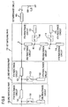
- Fig. 4 shows a matching circuit 100 according to a first embodiment.
- the matching circuit 100 shown in Fig. 4 operates as a matching circuit for each of signals in two frequency bands with center frequencies f 1 and f 2 (f 1 > f 2 ) shown in Fig. 5 .
- the matching circuit 100 is connected in series between port P 1 and port P 3 .
- the matching circuit 100 includes a first matching part 110, a second matching part 120, and a third matching part 130, which are connected in series in this order. That is, one end of the first matching part 110 is connected to port P 3 to which a first impedance circuit 105 is connected.
- the other end of the first matching part 110 is connected to one end of the second matching part 120.
- the other end of the second matching part 120 is connected to one end of the third matching part 130.
- the other end of the third matching part 130 is connected to port P 1 .
- the first impedance circuit 105 is provided for changing impedance (changing a resistance component is also allowed) between port P 2 and port P 3 in impedance matching. Whether the first impedance circuit 105 is required or not is determined by the design of the matching circuit 100. If the first impedance circuit 105 is required, the first impedance circuit 105 is formed by e.g. lumped-parameter elements (including a resistance) so that required impedance conversion is achieved. Seen in this light, the first impedance circuit 105 may be included in the matching circuit 100 as a component. However, it does not affect the subject matter of the present invention if the first impedance circuit 105 is not included in the matching circuit 100. Therefore, the matching circuit 100 will be described that it does not include the first impedance circuit 105 as a component, for convenience of explanation.
- a load (a circuit element) 199 that is connected in series to port P 2 and whose impedance has a frequency characteristic may be exemplified by an amplification device.
- the input/output impedance of the load 199 is denoted by the function Z L (f), where f represents the frequency of an AC signal.
- a circuitry 198 Connected to port P 1 is a circuitry 198.
- the input/output impedance of the circuitry 198 that does not depend on frequency (the system impedance) is denoted by Z 0 .
- the input/output impedance of the circuitry 198 is typically held at a predetermined constant value Z 0 , for example 50 or 75 ⁇ .
- Both of the load 199 and the circuitry 198 are represented by a symbol of resistance in the drawings for convenience.
- the first matching part 110 includes a second reactance circuit 112, a third reactance circuit 113, a fourth reactance circuit 114, a fifth reactance circuit 115, a sixth reactance circuit 116, a first switch 118, and a second switch 119.
- one end of the second reactance circuit 112 is connected to the connection point A between the second matching part 120 and the first impedance circuit 105.
- the other end of the second reactance circuit 112 is connected to one end of the third reactance circuit 113 and the fifth reactance circuit 115 is connected to the connection point B2 between the second reactance circuit 112 and the third reactance circuit 113 through the second switch 119.
- the other end of the third reactance circuit 113 is connected to one end of the fourth reactance circuit 114 and the sixth reactance circuit 116 is connected to the connection point B 1 between the third reactance circuit 113 and the fourth reactance circuit 114 through the first switch 118.
- the configuration of the first matching part 110 described here is not inconsistent with the description given above that "the first matching part 110 is connected in series". This is because port P 3 and the connection point R between the second matching part 120 and the first matching part 110 are implemented typically by transmission lines in real design.
- reactance circuits having reactance values include a single element such as a capacitor, an inductor, or a transmission line, or a combination of the same types of elements belonging among these elements, or a combination of different types of elements belonging among these elements.
- the switches used herein are not limited to contact type switches.
- the switches may be socalled switching elements having the capability of opening and closing a circuit, instead of providing contacts in the circuitry.
- Specific examples of the switches include MEMS (Micro-Electro Mechanical Systems) switches and switching diodes.
- the first switch 118 is turned on and the second switch 119 is turned off in a frequency band with center frequency f 1 , for example.
- the first switch 118 is turned off and the second switch 119 is turned on for a frequency band with center frequency f 2 .
- the second reactance circuit 112 has reactance values that can be obtained by a single element or circuit that constitutes the second reactance circuit 112 in impedance matching for each frequency band.
- the second reactance circuit 112 can be configured at the designer's discretion without any problems because the effects of the reactance values of the second reactance circuit 112 will be considered when designing the sixth reactance circuit 116 and the tenth reactance circuit 122, which will be described later, for the frequency band with center frequency f 1 and when designing the fifth reactance circuit 115 and the eighth reactance circuit 132, which will be described later, for the frequency band with center frequency f 2 .
- the fourth reactance circuit 114 is configured so that the impedance as viewed from the connection point B 1 between the fourth reactance circuit 114 and the third reactance circuit 113 toward the fourth reactance circuit 114 in the frequency band with center frequency f 1 is sufficiently large (the admittance is approximately 0).
- the fourth reactance circuit 114 may be an end-short-circuited line having an electrical length of 90 degrees at the center frequency f 1 .
- the words "impedance is sufficiently large (the admittance is approximately 0)" can be construed to mean that the impedance is large enough that a particular circuit (here the fourth reactance circuit 114) can be considered independently of the AC circuit at the frequency of the impedance matching.
- the impedance is sufficiently large (the admittance is approximately 0)" used in the following description.
- the third reactance circuit 113 is configured so that the impedance as viewed from the connection point B2 between the third reactance circuit 113 and the second reactance circuit 112 toward the third reactance circuit 113 is sufficiently large (the admittance is approximately 0).
- the third reactance circuit 113 may be implemented by a transmission line such that the sum of the electrical lengths of the third reactance circuit 113 and the fourth reactance circuit 114 becomes 90 degrees at the center frequency f 2 .
- the fourth reactance circuit 114 does not need to be taken into consideration in the frequency band with center frequency f 1 and the third reactance circuit 113 and the fourth reactance circuit 114 do not need to be taken into consideration in the frequency band with center frequency f 2 .
- the fifth reactance circuit 115 may be configured at the designer's discretion by using elements such as lumped-parameter elements or a transmission line as appropriate in the frequency band with center frequency f 2 without special restrictions.
- the sixth reactance circuit 116 can be configured at the designer's discretion by using elements such as lumped-parameter elements or a transmission line as appropriate in the frequency band with center frequency f 1 without special restrictions.
- the first matching part 110 can function as a different reactance element for each frequency band in response to a simple operation of turning on and off of the first switch 118 and the second switch 119.
- the first matching part 110 functions as different reactance elements for different frequency bands
- a different configuration of the first matching part 110 in which s transmission lines are simply connected in a cascade arrangement through s - 1 switches and the number of switches to turn on is changed to change the total length of the transmission lines connected.
- s transmission lines are simply connected in a cascade arrangement through s - 1 switches and the number of switches to turn on is changed to change the total length of the transmission lines connected.
- losses in the matching circuit due to insertion losses of switches would be significant.
- only one switch is placed in the on state for any of the frequency bands and therefore switch insertion loss in the matching circuit 100 is small.
- the second matching part 120 may be an impedance converter that has the capability of converting impedance in each frequency band.
- the second matching part 120 is a circuit that matches the impedance as viewed from the connection point R between the second matching part 120 and the first matching part 110 toward the first matching part 110 to the system impedance Z 0 in one of the frequency bands with center frequency f 1 and f 2 .
- the second matching part 120 will be described that is configured as a matching circuit that performs impedance matching in the frequency band with center frequency f 1 .
- the second matching part 120 corresponds to the main matching block 951 in Fig. 3 and can be implemented using a transmission line or lumped-parameter elements like the first matching part 110.
- a second matching part 120 configured with a ninth reactance circuit 121, a tenth reactance circuit 122, and a fourth switch 123 is shown in Fig. 6 .
- the ninth reactance circuit 121 is connected in series between the first matching part 110 and the third matching part 130
- the tenth reactance circuit 122 is connected to the connection point between the ninth reactance circuit 121 and the third matching part 130 through the fourth switch 123.
- the fourth switch 123 is turned on in the frequency band with center frequency f 1 and turned off in the frequency band with center frequency f 2 .
- the third matching part 130 can be implemented using a transmission line or lumped-parameter elements, like the first matching part 110.
- a third matching part 130 configured with a seventh reactance circuit 131, an eighth reactance circuit 132, and a third switch 133 is shown in Fig. 4 .
- the seventh reactance circuit 131 is connected in series between the second matching part 120 and port P 1
- the eighth reactance circuit 132 is connected to the connection point C between the seventh reactance circuit 131 and port P 1 through the third switch 133.
- the third switch 133 is turned off in the frequency band with center frequency f 1 and turned on in the frequency band with center frequency f 2 .
- the third switch 133 of the third matching part 130 is turned off and the fourth switch 123 of the second matching part 120 is turned on.
- the first matching part 110 in this case, the first switch 118 is turned on and the second switch 119 is turned off.
- the circuit part of the first matching part 110 excluding the fifth reactance circuit 115 (that is, the second, third, fourth, and sixth reactance circuits 112, 113, 114, and 116) and the second matching part 120 together perform impedance matching between the impedance Z(f 1 ) as viewed from port P 3 toward the first impedance circuit 105 and the system impedance Z 0 .
- the impedance Z(f 1 ) is the impedance resulting from the operation of the first impedance circuit 105 functioning as an impedance converter on the input/output impedance Z L (f 1 ) of the load 199.
- At least the sixth reactance circuit 116, the ninth reactance circuit 121, and the tenth reactance circuit 122 shown in Fig. 7 can be configured exclusively for impedance matching in the frequency band with center frequency f 1 .
- the ⁇ -shaped circuit comprising the sixth reactance circuit 116, the ninth reactance circuit 121, the tenth reactance circuit 122, the second reactance circuit 112, and the third reactance circuit 113 forms a double-stub matching circuit, and there is a designer's discretion with respect to the configurations of the two stubs (the sixth and tenth reactance circuits 116 and 122 in Fig. 7 ). This represents the expansion of the designer's discretion in configuring the ninth reactance circuit 121.
- the amount of delay of the delay circuit (corresponding to the ninth reactance circuit 121 in Fig. 7 ) is uniquely determined by the load Z L (f 1 ) in the single-stub matching circuit shown in Fig. 3 whereas in the configuration according to the first embodiment the designer's discretion in configuring the ninth reactance circuit 121 in the frequency band with center frequency f 1 is increased because of the addition of the sixth reactance circuit 116 in effect.
- the ninth reactance circuit 121 is implemented by a transmission line, for example, the line length of the ninth reactance circuit 121 can be designed shorter than that in a conventional configuration by appropriately configuring the sixth and tenth reactance circuits 116 and 122.
- impedance matching in the frequency band with center frequency f 1 can be achieved by choosing a circuit having a characteristic impedance equal to the system impedance Z 0 , for example a transmission line with the characteristic impedance Z 0 , in the frequency band with center frequency f 1 as the seventh reactance circuit 131.
- the third switch 133 of the third matching part 130 is turned on and the fourth switch 123 of the second matching part 120 is turned off.
- the first matching part 110 in this case, the first switch 118 is turned off and the second switch 119 is turned on.
- the circuit part of the first matching part 110 excluding the sixth reactance circuit 116 (that is, the second, third, fourth, and fifth reactance circuits 112, 113, 114, and 115 of the first matching part 110), the second matching part 120, and the third matching part 130 together perform impedance matching between the impedance Z(f 2 ) as viewed from port P 3 toward the first impedance circuit 105 and the system impedance Z 0 .
- the impedance Z(f 2 ) is the impedance resulting from the operation of the first impedance circuit 105 functioning as an impedance converter on the input/output impedance Z L (f 2 ) of the load 199.
- At least the fifth, seventh and eighth reactance circuits 115, 131, and 132 shown in Fig. 8 can be configured exclusively for impedance matching in the frequency band with center frequency f 2 .
- the seventh reactance circuit 131 is implemented by a transmission line that has a characteristic impedance of Z 0 in the frequency band with center frequency f 1 as described above, the line length of the transmission line etc. can be designed exclusively for impedance matching in the frequency band with center frequency f 2 .
- the ⁇ -shaped circuit comprising the fifth reactance circuit 115, the seventh reactance circuit 131, the eighth reactance circuit 132, the second reactance circuit 112, and the ninth reactance circuit 121
- there is a designer's discretion with respect to the configurations of the two stubs (the fifth and eighth reactance circuits 115 and 132 in Fig. 8 ).
- the seventh reactance circuit 131 is implemented by a transmission line, for example, the line length of the seventh reactance circuit 131 can be designed shorter than that in a conventional configuration by appropriately configuring the fifth and eighth reactance circuits 115 and 132.
- the seventh reactance circuit 131 of the third matching part 130 is configured on the basis of the interdependence with the configuration of the first matching part 110 and the configuration of the eighth reactance circuit 132 of the third matching part 130 corresponding to each frequency band.
- the matching circuit 100 shown in Fig. 4 is basically the same as the conventional matching circuit 950 shown in Fig. 3 in configuration, except that the first matching part 110 is added. Therefore, a concern arises that the addition of the first matching part 110 increases the matching circuit in size.
- the seventh reactance circuit 131 and the ninth reactance circuit 121 connected in series between ports P 1 and P 2 need to be designed so that appropriate amounts of delay in each frequency band are provided under the condition that the impedance Z 0 is sustained in each of the two or more frequency bands
- the first matching part 110 only need to have a particular reactance value in a selected operating frequency band.
- the reactance circuits included in the first matching part 110 has a high degree of flexibility in design, lumped-parameter elements, for example, can be used for the reactance circuits to reduce the size of the reactance circuits. Thus, the addition of the first matching part 110 does not significantly increase the size of the matching circuit.
- the insertion loss of the second switch 119 for connecting the fifth reactance circuit 115 and the insertion loss of the first switch 118 for connecting the sixth reactance circuit 116 vary depending on an alternating current flowing through the positions where the switches are inserted. Usually, a standing wave is distributed over circuitry. For example, if the second switch 119 is inserted at a node (a zero displacement point) of AC at a center frequency of f 2 , the insertion loss of the second switch 119 will be small whereas if the second switch 119 is inserted at an anti-node (a maximum displacement point) of AC, the insertion loss of the second switch 119 will be large.
- the insertion loss of the first switch 118 will be small, whereas if the first switch 118 is inserted at an anti-node of AC, the insertion loss of the first switch 118 will be large.
- the first switch 118 may be connected to a node of AC at a center frequency of f 1 and the second switch 119 may be connected to a node of AC at a center frequency of f 2 .
- connection point B 1 can be designed to be a position of nearly a node of AC at a center frequency of f 1 in the state that the sixth reactance circuit 116 is connected to the connection point B 1.
- connection point B2 can be designed to be a position of nearly a node of AC at a center frequency of f 2 in the state that the fifth reactance circuit 115 is connected to the connection point B2.
- the second reactance circuit 112 is preferably configured so as to have reactance values with which the insertion losses of the first and second switches 118 and 119 reduce as much as possible in designing the fifth and sixth reactance circuits 115 and 116 for each frequency band.
- a matching circuit 200 according to a second embodiment is shown in Fig. 9 .
- the matching circuit 200 shown in Fig. 9 functions as a matching circuit for each of two frequency bands with center frequencies of f 1 and f 2 (where F 1 > f 2 ).
- the fifth and sixth reactance circuits 115 and 116 are provided in the first matching part 110 for each of the two frequency bands. Accordingly, the desired matching circuit 100 can be configured in spite of the fact that the second reactance circuit 112 has reactance values that is obtained by a single element or circuit constituting the second reactance circuit 112 in each frequency band.
- the number of components of the first matching part 110 is reduced by designing the second reactance circuit 112 so as to have a predetermined reactance value in a certain frequency band.
- a first matching part 210 of the matching circuit 200 is configured as follows. One end of the second reactance circuit 112 is connected to the connection point A between the second matching part 120 and the first impedance circuit 105. The other end of the second reactance circuit 112 is connected to one end of the fourth reactance circuit 114 and the sixth reactance circuit 116 is connected to the connection point B 1 between the second reactance circuit 112 and the fourth reactance circuit 114 through the first switch 118.
- the fourth reactance circuit 114 is configured so that the impedance as viewed from the connection point B 1 between the fourth reactance circuit 114 and the second reactance circuit 112 toward the fourth reactance circuit 114 is sufficiently large (the admittance is approximately 0) in the frequency band with center frequency f 1 .
- the fourth reactance circuit 114 may be an end-short-circuited line having an electrical length of 90 degrees at the center frequency of f 1 .
- the design conditions for the tenth reactance circuit 122, which is a component of the second matching part 120, and the sixth reactance circuit 116, which is a component of the first matching part 210 are determined so that the second matching part 120 and the first matching part 210 practically carry out the function of impedance matching in the frequency band with central frequency f 1 .
- the design conditions for the eighth reactance circuit 132, which is a component of the third matching part 130, and the second reactance circuit 112, which is a component of the first matching part 210 are determined so that the third matching part 130 and the first matching part 210 practically carry out the function of impedance matching.
- the tenth reactance circuit 122, the eighth reactance circuit 132, the second reactance circuit 112, and the sixth reactance circuit 116 can be configured so that the design conditions are satisfied.
- the matching circuit 200 according to the second embodiment thus configured is capable of accomplishing impedance matching in each of the frequency bands with center frequencies f 1 and f 2 .
- a ninth reactance circuit 121 is implemented by a transmission line
- a configuration is chosen from design conditions for the sixth reactance circuit 116 that minimizes the line length of the ninth reactance circuit 121.
- a seventh reactance circuit 131 is implemented by a transmission line
- a configuration is chosen from the design conditions for the second reactance circuit 112 that minimizes the line length of the seventh reactance circuit 131.
- Matching circuits that accomplish impedance matching for each of two frequency bands have been shown in the first and second embodiments.
- a matching circuit that accomplishes impedance matching for each of more than two frequency bands will be shown.
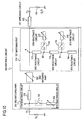
- Fig. 10 shows a matching circuit 300 according to the third embodiment.
- the matching circuit 300 according to the third embodiment has a configuration similar to that of the matching circuit 100 of the first embodiment. Therefore, the matching circuit 300 will be described in comparison to the matching circuit 100.
- a first matching part 310 of the matching circuit 300 has a configuration in which the fifth and sixth reactance circuits 115 and 116 of the matching circuit 100 are replaced with a fifth and sixth reactance circuits 315 and 316 that are variable reactance circuits whose reactance values can be changed among q kinds of values (where q is an integer greater than or equal to 2).
- the variable reactance circuit may be a variable capacitor whose capacitance can be changed or a variable inductor whose inductance can be changed, for example.
- a second matching part 320 of the matching circuit 300 has a configuration that allows its impedance to be changed among q kinds of impedances.
- Such a configuration of the second matching part 320 may be for example the same configuration as that of the second matching part 120 described with respect to the first embodiment except that the tenth reactance circuit 122 is replaced with a tenth reactance circuit that is a variable reactance circuit.
- the variable reactance circuit may also be a variable capacitor, a variable inductor or the like, for example.
- a third matching part 330 of the matching circuit 300 includes an eighth reactance circuit 332 whose reactance can be changed among q kinds of reactance values, in place of the eighth reactance circuit 132 of the matching circuit 100.
- the reactance circuits or the second matching part provides q kinds of reactance or impedance values, and switching can be made between the two circuit configurations by switches in a manner similar to that in the first embodiment. Consequently, impedance matching in up to 2*q frequency bands can be achieved.
- the seventh reactance circuit 131 can be configured without restriction by load Z L (f). Therefore, if the seventh reactance circuit 131 is implemented by a transmission line, the seventh reactance circuit 131 can be designed to have a minimized line length. For example, the seventh reactance circuit 131 may be designed to have the shortest possible line length at an appropriate one of q frequency bands that are available when the first switch 118 is turned on.
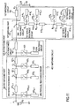
- a matching circuit 400 according to the fourth embodiment is shown in Fig. 11 .
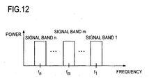
- the matching circuit 400 is an extended version of the matching circuit 100 of the first embodiment and implements impedance matching in each of n frequency bands with center frequencies of f 1 , f 2 , ..., f n (f 1 > f 2 > ... > f n ) shown in Fig. 12 .
- n is an integer greater than or equal to 3. If n is 2, the embodiment is equivalent to the first embodiment.
- a first matching part 410 in the matching circuit 400 includes a second reactance circuit 412 and n first series reactance circuits 413 1 to 413 n , which are connected in series.
- one end of the second reactance circuit 412 is connected to the connection point A between a second matching part 420 and the first impedance circuit 105.
- the other end of the second reactance circuit 412 is connected to the first series reactance circuit 413 n .
- the other end of the first series reactance circuit 413 n (the end to which the second reactance circuit 412 is not connected) is connected to one end of the first series reactance circuit 413 n-1 .
- the other end of the first series reactance circuit 413 n-1 (the end to which first series reactance circuit 413 n is not connected) is connected to one end of the first series reactance circuit 413 n-2 .
- Such connection is repeated to form a series connection so that the other end of the first series reactance circuit 413 2 (the end to which the first series reactance circuit 413 3 is not connected) is connected to one end of the first series reactance circuit 413 1 .
- a first parallel reactance circuit 414 n is connected to the connection point B n between the second reactance circuit 412 and the first series reactance circuit 413 n through a first switch 418 n .
- a first parallel reactance circuit 414 n-1 is connected to the connection point B n-1 between the first series reactance circuit 413 n and the first series reactance circuit 413 n-1 through a first switch 418n-1.
- n first series reactance circuits 413 1 to 413 n should be implemented as circuits of the same type.
- some of the n first series reactance circuits 413 1 to 413 n may be implemented by transmission lines and the others may be implemented by lumped-parameter elements, as appropriate.
- At least n reactance values can be set by turning on one of the first switches 418 1 to 418 n in the first matching part 410.
- the first switch 418 m is turned on for the frequency band with the m-th center frequency f m , where m is an integer greater than or equal to 1.
- the connection point B m at which the first switch 418 m is connected is located in a position where the impedance as viewed from the position toward the first series reactance circuits 413 1 to 413 m is sufficiently large (the admittance is approximately 0) in the frequency band with the m-th center frequency f m .
- the first series reactance circuit 413 1 may be an end-shorted line with a line length of ⁇ 1 /4 and the line length of the first series reactance circuit 413 m may be chosen such that the sum of the line lengths of the first series reactance circuits 413 1 to 413 m is ⁇ m /4.
- the wavelength ⁇ m corresponds to the m-th center frequency f m .
- the connection point B m can be designed preferably to be a position of nearly a node of AC at the m-th center frequency f m in the state that the m-th reactance 414 m circuit is connected to the connection point B m in view of minimizing the insertion loss of the first switch 418 m .
- the second matching part 420 is a circuit that matches the impedance as viewed from the connection point R between the second matching part 420 and the first matching part 410 toward the first matching part 410 to the system impedance Z 0 in the frequency band with the first center frequency f 1 .
- Such a second matching part 420 may have the configuration shown in Fig. 6 .
- a fourth switch 423 is turned on for the frequency band with the first center frequency f 1 and turned off for the frequency band with the m-th center frequency f m (m ⁇ 1).
- a third matching part 430 in the matching circuit 400 includes n - 1 second series reactance circuits 431 1 to 431 n-1 connected in series.
- one end of the second series reactance circuit 431 1 is connected to the other end of the second matching part 420 (the end opposite to the end to which the first impedance circuit 105 is connected).
- the other end of the second series reactance circuit 431 1 is connected to the second series reactance circuit 431 2 .
- the other end of the second series reactance circuit 431 2 (the end to which the second series reactance circuit 431 1 is not connected) is connected to one end of the second series reactance circuit 431 3 .
- the other end of the second series reactance circuit 431 3 (the end to which the second series reactance circuit 431 2 is not connected) is connected to one end of the second series reactance circuit 413 4 .
- Such connection is repeated to form a series connection so that the other end of the second series reactance circuit 431 n-2 (the end to which the second series reactance circuit 431 n-3 is not connected) is connected to one end of the second series reactance circuit 431 n-1 .
- the other end of the second series reactance circuit 431 n-1 is connected to port P 1 .
- a second parallel reactance circuit 432 1 is connected to the connection point C 1 between the series reactance circuit 431 1 and the second series reactance circuit 431 2 though a second switch 433 1 .
- a second parallel reactance circuit 432 2 is connected to the connection pint C 2 between the second series reactance circuit 431 2 and the second series reactance circuit 431 3 through a second switch 433 2 .
- the second parallel reactance circuit 432 n-1 is connected to the connection point C n-1 between the series reactance circuit 431 n-1 and port P 1 through the second switch 433 n-1 .
- n - 1 second parallel reactance circuits 432 1 to 432 n-1 should be implemented as circuits of the same type.
- some of the n - 1 second parallel reactance circuits 432 1 to 432 n-1 may be implemented by transmission lines and the other may be implemented by lumped-parameter elements, as appropriate.
- the n - 1 second series reactance circuits 431 1 to 431 n-1 need to be designed so that a characteristic impedance of Z 0 is provided in each of the two or more frequency bands in order to match to the system impedance Z 0 and an appropriate amount of delay for each frequency band needs to be designed.
- the switches in the matching circuit 400 are turned on and off according to each frequency band as follows.
- the first parallel reactance circuit 414 1 , the ninth reactance circuit 421, and the tenth reactance circuit 422 can be configured exclusively for impedance matching in the frequency band with the first center frequency f 1 .
- the first parallel reactance circuit 414 m-1 , the second series reactance circuit 431 m , and the second parallel reactance circuit 432 m-1 can be configured exclusively for impedance matching in the frequency band with the m-th center frequency f m . Because there is a designer's discretion with respect to the configurations of the first parallel reactance circuit 414 m and the second parallel reactance circuit 432 m-1 , the designer's discretion is expanded in configuring the second series reactance circuit 431 m-1 .
- the ninth reactance circuit 421 and the n - 1 second series reactance circuits 431 1 to 431 n-1 are implemented by transmission lines, the line lengths of the ninth reactance circuit 421 and the second series reactance circuits 431 1 to 431 n-1 can be further reduced by appropriately configuring the tenth reactance circuit 422, the first parallel reactance circuits 414 1 to 414 n , and the second parallel reactance circuits 432 1 to 432 n-1 .
- the number of components of the first matching part 410 in the matching circuit 400 can be reduced by designing the second reactance circuit 112 so as to take a predetermined reactance value at a certain particular frequency.
- the second reactance circuit 412 is designed to take a predetermined reactance value in the frequency band with the n-th center frequency f n , the first series reactance circuits 413 n , the first parallel reactance circuits 414 n , and the first switches 418 n , which are the components of the first matching part 410 in the matching circuit 400, can be omitted from the matching circuit 400 in the fourth embodiment (see Fig. 13 ).
- the design conditions for the tenth reactance circuit 422, which is a component of the second matching part 420, and the first parallel reactance circuit 414 1 , which is a component of the first matching part 410, are determined so that the second matching part 420 and the first matching part 410 practically carry out the function of impedance matching in the frequency band with central frequency f 1 .
- the design conditions for the second parallel reactance circuit 432 m-1 which is a component of the third matching part 430 and the first parallel reactance circuit 414 m which is a component of the first matching part 410 are determined so that the third matching part 430 and the first matching part 410 practically carry out the function of matching impedances.
- the design conditions for the second parallel reactance circuit 432 n-1 , which is a component of the third matching part 430, and the second reactance circuit 412, which is a component of the first matching part 410, are determined so that the third matching part 430 and the first matching part 410 practically carry out the function of impedance matching.
- the second reactance circuit 412 and the first parallel reactance circuits 414 1 to 414 n-1 can be configured in accordance with these design conditions.
- the matching circuit 400' which is a variation of the fourth embodiment can implement impedance matching in each of the frequency bands with center frequencies of f 1 to f n , like the matching circuit 400 of the fourth embodiment.
- a matching circuit 500 according to a fifth embodiment will be described.
- the first matching part may have any configuration that can provide a predetermined reactance value in accordance with each frequency band for which impedance matching is to be performed.
- the matching circuit 500 includes a first matching part 510 configured to use a single-pole n-throw switch 518 to select one of n reactance circuits 513 1 to 513 n to provide a predetermined reactance value according to each frequency band for which impedance matching is to be performed. Only the differences of the matching circuit 500 from the matching circuit 400 will be described below based on the configuration of the matching circuit 400 according to the fourth embodiment.
- the first matching part 510 of the matching circuit 500 includes a second reactance circuit 512, a single-pole n-throw switch 518, and n reactance circuits 513 1 to 513 n .
- One end of the second reactance circuit 512 is connected to connection point A, the other end of the second reactance circuit 512 is connected to the input terminal of the single-pole n-throw switch 518, and the reactance circuits 513 1 to 513 n are connected to the output terminals of the single-pole n-throw switch 518.
- the n reactance circuits 513 1 to 513 n should be implemented as circuits of the same type.
- some of the n reactance circuits 513 1 to 513 n may be implemented by transmission lines and the others by lumped-parameter elements, for example, as appropriate.
- the first matching part 510 selects one of the reactance circuits 513 1 to 513 n using the single-pole n-throw switch 518 in response to any of second switches 433 1 to 433 n-1 and a fourth switch 423 being turned on.
- a predetermined reactance value can be provided by the reactance circuit thus selected and the second reactance circuit 512.
- the ninth reactance circuit may be connected in series between the first and third matching parts and the tenth reactance circuit may be connected to the connection point between the ninth reactance circuit and the third matching part without using the fourth switch. That is, a configuration is possible that is equivalent to the one shown in Fig. 6 in which the fourth switch is always in the on state.
- the second matching part in the configuration in which the reactance circuits in the first matching part and the reactance circuits in the third matching part form a ⁇ -shaped circuit is no more than a circuit that has a constant reactance value as apparent from the description of the embodiments given above and therefore turning off the fourth switch is not an essential technical requirement.
- the second matching part can flexibly be configured as an impedance converter.
- a multiband amplifier can be implemented.
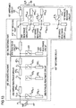
- Fig. 15 shows a multiband amplifier 700 in which the matching circuit 200 according to the second embodiment is used as an output matching circuit for an amplification device 600.
- Examples of the amplification device 600 include a transistor, FET (Field-Effect Transistor), MOSFET (Metal Oxide Semiconductor FET), and TFT (Thin Film Transistor). While n-channel junction FETs are shown as amplification devices in the drawings, it is not intended to limit amplification devices to n-channel junction FETs but they are shown illustrative only.
- the line length of each transmission line is determined by calculation using a microstrip line on a 0.785-thick substrate with a relative permittivity of 2.2 as an example. While details of the input matching circuit 701 is not shown, the input matching circuit 701 may be the one described with respect to the first or second embodiments of the present invention or may be a broadband matching circuit capable of achieving impedance matching in the range from frequency f 1 to f 2 .
- the input matching circuit 701 may be implemented by a multiband matching circuit disclosed in reference literature ( Atsushi Fukuda, Hiroshi Okazaki, and Shoichi Narahashi, "Power Amplifier for Broadband Applications Beyond the Third Generation --- Multi-band, High-efficiency Power Amplifier using MEMS switches for Mobile Terminals ---", NTT DoCoMo Technical Journal Vol. 8, No. 3, pp. 24 - 31, Oct. 2006 ).
- One end of the input matching circuit 701 is connected to the FET 600 and the other end is connected to a signal source 702 with a signal source impedance of 50 ⁇ .
- the first and fourth switches 118 and 123 are turned on in the frequency band with central frequency f 1 .
- the fourth reactance circuit 114 in the first matching part 210 is implemented by a transmission line with a physical length of 11 mm, one end (the end to which the second reactance circuit 112 is not connected) of which is short-circuited by a capacitor 707 with a capacitance of 100 pF, for example.
- the physical length is equivalent to an electrical length of approximately 90 degrees at center frequency f 1 and therefore the impedance as viewed from the connection point B 1 between the second reactance circuit 112 and the fourth reactance circuit 114 toward the fourth reactance circuit 114 is sufficiently large (the admittance is approximately 0).
- impedance matching in the frequency band with center frequency of f 1 can be established by implementing the sixth, ninth, and tenth reactance circuits 116, 121, and 122 by transmission lines having lengths of 3 mm, 13 mm, and 17 mm, respectively.
- the seventh reactance circuit 131 is a transmission line with a characteristic impedance of Z 0 and therefore the physical length does not cause impedance mismatch in the frequency band with center frequency f 1 .
- the second reactance circuit 112 must be considered.
- the sum of the reactance values of the second and sixth reactance circuits 112 and 116 is designed in design for the frequency band with center frequency f 1 , and then the physical length of the sixth reactance circuit 116 is determined with considering the physical length of the second reactance circuit 112 obtained by impedance matching in the frequency band with center frequency f 2 , which will be described later.
- the first switch 118 is turned off, the third switch 133 is turned on, and the fourth switch 123 is turned off in the frequency band with center frequency f 2 .
- impedance matching in the frequency band with center frequency f 2 can be established by implementing the second reactance circuit, seventh reactance circuit, and eighth reactance circuit 112, 131, and 132 by transmission lines with lengths of 3 mm, 12 mm, and 28 mm, respectively.
- While the second, fourth, sixth, eighth, and tenth reactance circuits 112, 114, 116, 132, and 122 are implemented by transmission lines in the example described above, these reactance circuits can be implemented by lumped-parameter elements as mentioned above to reduce them in size because lumped-parameter elements can be designed so as to satisfy design requirements in one fixed frequency band with center frequency f 1 or f 2 .
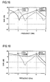
- Fig. 16 shows the gain-frequency response of the multiband amplifier 700 shown in Fig. 15 .
- the first, second and third switches are ideal switches whose losses are zero in the on state and whose isolation is infinite in the off state. While the simulation will be described in which such ideal switches are used, amplitude-frequency response and phase-frequency response of the switches, like other components, should also be considered in real design.
- Fig. 17 shows as a comparative example a multiband amplifier 800 configured with an input matching circuit 701 used in the multiband amplifier 700 shown in Fig. 15 and an output matching circuit 850 with a conventional configuration in which the first matching part 210 is not added.
- a fourth switch 823 is turned on and a third switch 833 is turned off in the frequency band with center frequency f 1 .
- the ninth and tenth reactance circuits may be implemented by transmission lines with lengths of 22 mm and 7 mm, respectively.
- the fourth switch 823 is turned off and the third switch 833 is turned on.
- the seventh and eighth reactance circuits 831 and 832 must be implemented by transmission lines with lengths of 19 mm and 9 mm, respectively.
- the sum of the line lengths of the seventh and ninth reactance circuits 831 and 821 is 41 mm.
- a longer physical length of the transmission lines that form the ninth and seventh reactance circuits 821 and 831 is required as compared with that the multiband amplifier 700 shown in Fig. 15 .
- the use of the matching circuit according to the present invention can reduce the size of the reactance circuits connected in series.
- Fig. 18 shows the gain-frequency response of the multiband amplifier 800 shown in Fig. 17 . Since the gains of the multiband amplifier 700 shown in Fig. 15 in each of two frequency bands are comparable to the gains of the multiband amplifier 800 shown in Fig. 17 , it is apparent that, according to the configuration of the present invention, a matching circuit can be reduced in size while maintaining a good characteristic.
- the matching circuit according to the present invention can be used in an AC circuit and not particularly limited to an AC frequency to be directed, but is useful in an AC circuit that operates in the quasi-microwave range to the microwave range, for example, that is, at high frequencies in the range from 100 MHz to 30 GHz.
Landscapes
- Engineering & Computer Science (AREA)
- Power Engineering (AREA)
- Microwave Amplifiers (AREA)
- Amplifiers (AREA)
- Transmitters (AREA)
Claims (10)
- Anpassungsschaltung zum Durchführen einer Impedanzanpassung in einem Betriebsfrequenzband, auswählbar aus n Frequenzbändern b1 bis bn, zwischen einem Schaltungselement (199), dessen Impedanz eine Frequenzcharakteristik hat, und einem Schaltkreis (198) mit einer konstanten Impedanz, wobei n eine vorgegebene Ganzzahl größer oder gleich 2 ist, wobei die Anpassungsschaltung aufweist:einen ersten Anpassungsteil, dessen eines Ende mit dem Schaltungselement (199) verbunden ist, einen zweiten Anpassungsteil (420), dessen eines Ende mit dem anderen Ende des ersten Anpassungsteils verbunden ist, und einen dritten Anpassungsteil (430), dessen eines Ende mit dem anderen Ende des zweiten Anpassungsteils (420) verbunden ist und dessen anderes Ende mit dem Schaltkreis (198) verbunden ist;wobei der erste Anpassungsteil Reaktanzschaltungen und Schalter aufweist, die verbunden sind, um ein Reaktanzelement zu bilden, dessen Reaktanzwert, in Übereinstimmung mit dem ausgewählten Betriebsfrequenzband, durch Ändern des AN/AUS-Zustands der Schalter geändert werden kann;wobei der zweite Anpassungsteil (420) eine Reaktanzschaltung H (421), deren eines Ende mit dem anderen Ende des ersten Anpassungsteils verbunden ist und deren anderes Ende mit einem Ende des dritten Anpassungsteils (430) verbunden ist, und eine Reaktanzschaltung I (422) aufweist, die mit dem anderen Ende der Reaktanzschaltung H (421) verbunden ist,wobei der zweite Anpassungsteil (420) und der erste Anpassungsteil ausgebildet sind, in einem Basisfrequenzband b1 der Frequenzbänder, eine π-förmige Doppel-Stub-Anpassungsschaltung zu bilden, wobei das Reaktanzelement, das durch den ersten Anpassungsteil implementiert ist, einen der Stubs der Doppel-Stub-Anpassungsschaltung darstellt, während die Reaktanzschaltung I (422) den anderen der Stubs der Doppel-Stub-Anpassungsschaltung darstellt, und der zweite Anpassungsteil (420) ein Impedanz-Konverter ist, der in jedem der Frequenzbänder arbeitet, außer dem Basisfrequenzband b1; undder dritte Anpassungsteil (130; 430) aufweistin dem Fall von n>2n-1 Reaktanzschaltungen E1 bis En-1 (4311 bis 431n-1), in einer Kaskade verbunden auf eine Weise, dassein Ende der Reaktanzschaltung E1 (4311) mit dem anderen Ende der Reaktanzschaltung H (421) verbunden ist,ein Ende jeder Reaktanzschaltung Ek, 2 ≤ k ≤ n-1, über einen jeweiligen Verbindungspunkt Ck-1 mit dem anderen Ende der jeweiligen angrenzenden Reaktanzschaltung Ek-1 verbunden ist, unddas andere Ende der Reaktanzschaltung En-1 (431n-1) über einen Verbindungspunkt Ck-1 mit dem Schaltkreis (198) verbunden ist,jede der Reaktanzschaltungen E1 bis En-1 (4311 bis 431n-1) eine charakteristische Impedanz hat, die gleich der Impedanz des Schaltkreises (198) ist;n-1 Schalter G1 bis Gn-1 (4331 bis 433n-1), wobei ein Ende jedes Schalters mit einem jeweiligen der Verbindungspunkte C1 bis Cn-1 verbunden ist; undn-1 Reaktanzschaltungen F1 bis Fn-1 (4321 bis 432n-1), von denen jeweils ein Ende mit dem anderen Ende eines entsprechenden der Schalter G1 bis Gn-1 (4331 bis 433n-1) verbunden ist,wobei die n-1 Reaktanzschaltungen E1 bis En-1 (4311 bis 431n-1), die n-1 Schalter G1 bis Gn-1 (4331 bis 433n-1) und die n-1 Reaktanzschaltungen F1 bis Fn-1 (4321 bis 432n-1) jeweils den Frequenzbändern b2 bis bn der Frequenzbänder b1 bis bn entsprechen,die n-1 Schalter G1 bis Gn-1 (4331 bis 433n-1) ausgebildet sind, dass alleausgeschaltet sind in Reaktion darauf, dass das Basisfrequenzband b1 als das Betriebsfrequenzband ausgewählt ist, und ausgebildet sind, dass alle, außer einem ausgewählten Schalter Gj, 1 ≤ j ≤ n-1, ausgeschaltet sind in Reaktion darauf, dass eines der Frequenzbänder b2 bis bn, außer das Basisfrequenzband b1, als das Betriebsfrequenzband ausgewählt ist, wobei der jeweilige angeschaltete Schalter Gj dem ausgewählten Betriebsfrequenzband bj+1 entspricht, so dass die Reaktanzschaltung Fj, die mit dem ausgewählten Schalter Gj verbunden ist, mit dem Verbindungspunkt Cj verbunden ist, und somit bilden der dritte Anpassungsteil (430) und die ersten und zweiten Anpassungsteile zusammen eine πförmige Doppel-Stub-Anpassungsschaltung, wobei das Reaktanzelement, das durch den ersten Anpassungsteil implementiert ist, einen der Stubs der Doppel-Stub-Anpassungsschaltung darstellt, während die Reaktanzschaltung Fj den anderen der Stubs der Doppel-Stub-Anpassungsschaltung darstellt, undin dem Fall von n=2eine Reaktanzschaltung E1 (131), die eine charakteristische Impedanz gleich der Impedanz des Schaltkreises (198) hat und deren eines Ende mit dem anderen Ende der Reaktanzschaltung H (421) verbunden ist und das andere Ende mit dem Schaltkreis (198) verbunden ist,einen Schalter G1 (133), dessen eines Ende mit dem Verbindungspunkt C1 zwischen der Reaktanzschaltung E1 (131) und dem Schaltkreis (198) verbunden ist; undeine Reaktanzschaltung F1 (132), deren eines Ende mit dem anderen Ende des Schalters G1 (133) verbunden ist,wobei der Schalter G1 (133) ausgebildet ist, ausgeschaltet zu sein in Reaktion darauf, dass das Basisfrequenzband b1 als das Betriebsfrequenzband ausgewählt ist, und ausgebildet ist, angeschaltet zu sein in Reaktion darauf, dass das Frequenzband b2 als das Betriebsfrequenzband ausgewählt ist, so dass die Reaktanzschaltung F1 mit dem Verbindungspunkt C1 verbunden ist, und somit bilden der dritte Anpassungsteil (130) und die ersten und zweiten Anpassungsteile zusammen eine π-förmige Doppel-Stub-Anpassungsschaltung, wobei das Reaktanzelement, das durch den ersten Anpassungsteil implementiert ist, einen der Stubs der Doppel-Stub-Anpassungsschaltung darstellt, während die Reaktanzschaltung F1 den anderen der Stubs der Doppel-Stub-Anpassungsschaltung darstellt,wobei die Anpassungsschaltung dadurch gekennzeichnet ist, dass:der erste Anpassungsteil aufweist:eine Reaktanzschaltung A, deren eines Ende mit einem Verbindungspunkt (A) zwischen dem Schaltungselement (199) und dem einen Ende des zweiten Anpassungsteils (420) verbunden ist;n Reaktanzschaltungen RC1 bis RCn, die jeweils einem jeweiligen der n Frequenzbänder b1 bis bn entsprechen; undeine Schalter-Schaltung, die n Schalter umfasst, die jeweils einem jeweiligen der Frequenzbänder b1 bis bn entsprechen, wobei ein Ende von jedem der n Schalter mit dem anderen Ende der Reaktanzschaltung A verbunden ist und das andere Ende von jedem der n Schalter mit einer jeweiligen der Reaktanzschaltungen RC1 bis RCn verbunden ist,wobei die Schalter-Schaltung ausgebildet ist, in Reaktion darauf, dass eines der Frequenzbänder b1 bis bm als das Betriebsfrequenzband ausgewählt ist, nur den Schalter, der dem ausgewählten Betriebsfrequenzband entspricht, in einem AN-Zustand zu haben und alle anderen der n Schalter in einem AUS-Zustand,wodurch ein Reaktanzelement des ersten Anpassungsteils implementiert wird und einen Reaktanzwert hat, der abhängig von dem ausgewählten Betriebsfrequenzband differiert und der bestimmt wird durch die Reaktanzschaltung verbunden mit dem einen Schalter, der dem ausgewählten Betriebsfrequenzband entspricht.
- Anpassungsschaltung gemäß Anspruch 1, wobei
die Schalter-Schaltung (518) einen einpoligen n-Wechselschalter aufweist, der einen Eingangsanschluss hat, der mit dem anderen Ende der Reaktanzschaltung A (512) verbunden ist, und n Ausgangsanschlüsse, die jeweils mit den n Reaktanzschaltungen RC1 bis RCn (5131 bis 513n) verbunden sind. - Anpassungsschaltung zum Durchführen einer Impedanzanpassung in einem Betriebsfrequenzband, auswählbar aus n Frequenzbändern b1 bis bn, zwischen einem Schaltungselement (199), dessen Impedanz eine Frequenzcharakteristik hat, und einem Schaltkreis (198) mit einer konstanten Impedanz, wobei n eine vorgegebene Ganzzahl größer oder gleich 2 ist, wobei die Anpassungsschaltung aufweist:einen ersten Anpassungsteil (110; 410), dessen eines Ende mit dem Schaltungselement (199) verbunden ist, einen zweiten Anpassungsteil (120; 420), dessen eines Ende mit dem anderen Ende des ersten Anpassungsteils verbunden ist, und einen dritten Anpassungsteil (130; 430), dessen eines Ende mit dem anderen Ende des zweiten Anpassungsteils (120; 420) verbunden ist und dessen anderes Ende mit dem Schaltkreis (198) verbunden ist;wobei der erste Anpassungsteil (110; 410) Reaktanzschaltungen und Schalter aufweist, die verbunden sind, um ein Reaktanzelement zu bilden, dessen Reaktanzwert, in Übereinstimmung mit dem ausgewählten Betriebsfrequenzband, durch Ändern des AN/AUS-Zustands der Schalter geändert werden kann;wobei der zweite Anpassungsteil (120; 420) eine Reaktanzschaltung H (121; 421), deren eines Ende mit dem anderen Ende des ersten Anpassungsteils (110; 410) verbunden ist und deren anderes Ende mit einem Ende des dritten Anpassungsteils (130; 430) verbunden ist, und eine Reaktanzschaltung I (122; 422) aufweist, die mit dem anderen Ende der Reaktanzschaltung H (121; 421) verbunden ist;wobei der zweite Anpassungsteil (120; 420) und der erste Anpassungsteil (110; 410) ausgebildet sind, in einem Basisfrequenzband b1 der Frequenzbänder, eine π-förmige Doppel-Stub-Anpassungsschaltung zu bilden, wobei das Reaktanzelement, das durch den ersten Anpassungsteil (110; 410) implementiert wird, einen der Stubs der Doppel-Stub-Anpassungsschaltung darstellt, während die Reaktanzschaltung I (122; 422) den anderen der Stubs der Doppel-Stub-Anpassungsschaltung darstellt, und der zweite Anpassungsteil (120; 420) ein Impedanz-Konverter ist, der in jedem der Frequenzbänder arbeitet, außer dem Basisfrequenzband b1; undder dritte Anpassungsteil (130; 430) aufweistin dem Fall von n>2n-1 Reaktanzschaltungen E1 bis En-1 (4311 bis 431n-1), in einer Kaskade verbunden auf eine Weise, dassein Ende der Reaktanzschaltung E1 (4311) mit dem anderen Ende der Reaktanzschaltung H (121; 421) verbunden ist,ein Ende jeder Reaktanzschaltung Ek, 2 ≤ k ≤ n-1, über einen jeweiligen Verbindungspunkt Ck-1 mit dem anderen Ende der jeweiligen angrenzenden Reaktanzschaltung Ek-1 verbunden ist, unddas andere Ende der Reaktanzschaltung En-1 (431n-1) über einen Verbindungspunkt Cn-1 mit dem Schaltkreis (198) verbunden ist,jede der Reaktanzschaltungen E1 bis En-1 (4311 bis 431n-1) eine charakteristische Impedanz hat, die gleich der Impedanz des Schaltkreises (198) ist;n-1 Schalter G1 bis Gn-1 (4331 bis 433n-1), wobei ein Ende jedes Schalters mit einem jeweiligen der Verbindungspunkte C1 bis Cn-1 verbunden ist; undn-1 Reaktanzschaltungen F1 bis Fn-1 (4321 bis 432n-1), von denen jeweils ein Ende mit dem anderen Ende eines entsprechenden der Schalter G1 bis Gn-1 (4331 bis 433n-1) verbunden ist,wobei die n-1 Reaktanzschaltungen E1 bis En-1 (4311 bis 431n-1), die n-1 Schalter G1 bis Gn-1 (4331 bis 433n-1) und die n-1 Reaktanzschaltungen F1 bis Fn-1 (4321 bis 432n-1) jeweils den Frequenzbändern b2 bis bn der Frequenzbänder b1 bis bn entsprechen,die n-1 Schalter G1 bis Gn-1 (4331 bis 433n-1) ausgebildet sind, dass alleausgeschaltet sind in Reaktion darauf, dass das Basisfrequenzband b1 als das Betriebsfrequenzband ausgewählt ist, und ausgebildet sind, dass alle, außer einem ausgewählten Schalter Gj, 1 ≤ j ≤ n-1, ausgeschaltet sind in Reaktion darauf, dass eines der Frequenzbänder b2 bis bn, außer das Basisfrequenzband b1, als das Betriebsfrequenzband ausgewählt ist, wobei der jeweilige angeschaltete Schalter Gj dem ausgewählten Betriebsfrequenzband bj+1 entspricht, so dass die Reaktanzschaltung Fj, die mit dem ausgewählten Schalter Gj verbunden ist, mit dem Verbindungspunkt Cj verbunden ist, und somit bilden der dritte Anpassungsteil (130; 430) und die ersten und zweiten Anpassungsteile zusammen eine π-förmige Doppel-Stub-Anpassungsschaltung, wobei das Reaktanzelement, das durch den ersten Anpassungsteil (110; 410) implementiert ist, einen der Stubs der Doppel-Stub-Anpassungsschaltung darstellt, während die Reaktanzschaltung Fj den anderen der Stubs der Doppel-Stub-Anpassungsschaltung darstellt, undin dem Fall von n=2,eine Reaktanzschaltung E1 (131), die eine charakteristische Impedanz gleich der Impedanz des Schaltkreises (198) hat und deren eines Ende mit dem anderen Ende der Reaktanzschaltung H (421) verbunden ist und das andere Ende mit dem Schaltkreis (198) verbunden ist,einen Schalter G1 (133), dessen eines Ende mit dem Verbindungspunkt C1 zwischen der Reaktanzschaltung E1 (131) und dem Schaltkreis (198) verbunden ist; undeine Reaktanzschaltung F1 (132), deren eines Ende mit dem anderen Ende des Schalters G1 (133) verbunden ist,wobei der Schalter G1 (133) ausgebildet ist, ausgeschaltet zu sein in Reaktion darauf, dass das Basisfrequenzband b1 als das Betriebsfrequenzband ausgewählt ist, und ausgebildet ist, angeschaltet zu sein in Reaktion darauf, dass das Frequenzband b2 als das Betriebsfrequenzband ausgewählt ist, so dass die Reaktanzschaltung F1 mit dem Verbindungspunkt C1 verbunden ist, und somit bilden der dritte Anpassungsteil (130) und die ersten und zweiten Anpassungsteile (120; 420) zusammen eine π-förmige Doppel-Stub-Anpassungsschaltung, wobei das Reaktanzelement, das durch den ersten Anpassungsteil (110; 410) implementiert ist, einen der Stubs der Doppel-Stub-Anpassungsschaltung darstellt, während die Reaktanzschaltung F1 den anderen der Stubs der Doppel-Stub-Anpassungsschaltung darstellt,wobei die Anpassungsschaltung dadurch gekennzeichnet ist, dass:der erste Anpassungsteil (110; 410) aufweist:eine Reaktanzschaltung A (112; 412), deren eines Ende mit einem Verbindungspunkt (A) zwischen dem Schaltungselement (199) und dem einen Ende des zweiten Anpassungsteils (120; 420) verbunden ist;n Reaktanzschaltungen B1 bis Bn (113, 114; 4131 bis 413n), die in einer Kaskade verbunden sind und jeweils einem jeweiligen der n Frequenzbänder b1 bis bn entsprechen;n Reaktanzschaltungen RC1 bis RCn (116, 115; 4141 bis 414n), die jeweils einem jeweiligen der n Frequenzbänder b1 bis bn entsprechen; undeine Schalter-Schaltung, die n Schalter D1 bis Dn (118, 119; 4181 bis 418n) umfasst, die jeweils einem jeweiligen der n Frequenzbänder b1 bis bn entsprechen,wobei ein Ende jeder Reaktanzschaltung Bk (4131 bis 413n-1) mit dem anderen Ende der angrenzenden Reaktanzschaltung Bk+1, 1 ≤ k ≤ n-1, verbunden ist,ein Ende der Reaktanzschaltung Bn (413n) mit dem anderen Ende der Reaktanzschaltung A (112; 412) verbunden ist;ein Ende jedes Schalters Dm (4181 bis 418n), 1 ≤ m ≤ n, mit dem anderen Ende der Reaktanzschaltung Bm (4131 bis 413n) verbunden ist, undein Ende der Reaktanzschaltung RCm (4141 bis 414n) mit dem anderen Ende des Schalters Dm (4181 bis 418n) verbunden ist;wobei die Schalter-Schaltung ausgebildet ist, den Schalter Dm angeschaltet zu haben und alle Schalter D1 bis Dn, außer dem Schalter Dm, ausgeschaltet zu haben in Reaktion darauf, dass ein Frequenzband bm als das Betriebsfrequenzband ausgewählt ist, wobei der Reaktanzwert der Reaktanzschaltung Bm derart ist, dass die Admittanz der Kaskadenanordnung der Reaktanzschaltungen B1 bis Bm (4131 bis 413m), betrachtet von dem einen Ende der Reaktanzschaltung Bm zu der Kaskadenanordnung hin, in dem ausgewählten Betriebsfrequenzband bm ungefähr null wird, so dass das Reaktanzelement für das ausgewählte Betriebsfrequenzband bm implementiert wird durch eine Kaskadenanordnung der Reaktanzschaltung A (112; 412), alle der Reaktanzschaltungen B1 bis Bn, außer für die Reaktanzschaltungen B1 bis Bm, und der Reaktanzschaltung RCm,wodurch das Reaktanzelement, implementiert durch die Kaskadenanordnung für ein Betriebsfrequenzband bm, nur einen Schalter Dm in einem AN-Zustand umfasst und der Reaktanzwert des Reaktanzelements für das ausgewählte Betriebsfrequenzband bm durch die Reaktanzschaltung RCm bestimmt wird.
- Anpassungsschaltung gemäß Anspruch 3, wobei, wenn αn den Verbindungspunkt zwischen der Reaktanzschaltung Bn (413n) und der Reaktanzschaltung A (112; 412; 512) bezeichnet, und αk, 1 ≤ k ≤ n-1, den Verbindungspunkt zwischen der Reaktanzschaltung Bk und der Reaktanzschaltung Bk+1 bezeichnet, der Verbindungspunkt αi, 1 ≤ i ≤ n, ein Teil ist, der ein Knoten eines Wechselstroms in dem i-ten Frequenzband ist.
- Anpassungsschaltung zum Durchführen einer Impedanzanpassung in einem Betriebsfrequenzband, auswählbar aus n Frequenzbändern b1 bis bn, zwischen einem Schaltungselement (199), dessen Impedanz eine Frequenzcharakteristik hat, und einem Schaltkreis (198) mit einer konstanten Impedanz, wobei n eine vorgegebene Ganzzahl größer oder gleich 2 ist, wobei die Anpassungsschaltung aufweist:einen ersten Anpassungsteil (210; 410), dessen eines Ende mit dem Schaltungselement (199) verbunden ist, einen zweiten Anpassungsteil (120; 420), dessen eines Ende mit dem anderen Ende des ersten Anpassungsteils verbunden ist, und einen dritten Anpassungsteil (130; 430), dessen eines Ende mit dem anderen Ende des zweiten Anpassungsteils (120; 420) verbunden ist und dessen anderes Ende mit dem Schaltkreis (198) verbunden ist;wobei der erste Anpassungsteil (210; 410) Reaktanzschaltungen und Schalter aufweist, die verbunden sind, um ein Reaktanzelement zu bilden, dessen Reaktanzwert, in Übereinstimmung mit dem ausgewählten Betriebsfrequenzband, durch Ändern des AN/AUS-Zustands der Schalter geändert werden kann;wobei der zweite Anpassungsteil (120; 420) eine Reaktanzschaltung H (121; 421), deren eines Ende mit dem anderen Ende des ersten Anpassungsteils (210; 410) verbunden ist und deren anderes Ende mit einem Ende des dritten Anpassungsteils (130; 430) verbunden ist, und eine Reaktanzschaltung I (122; 422) aufweist, die mit dem anderen Ende der Reaktanzschaltung H (121; 421) verbunden ist;wobei der zweite Anpassungsteil (120; 420) und der erste Anpassungsteil (210; 410) ausgebildet sind, in einem Basisfrequenzband b1 der Frequenzbänder, eine π-förmige Doppel-Stub-Anpassungsschaltung zu bilden, wobei das Reaktanzelement, das durch den ersten Anpassungsteil (210; 410) implementiert wird, einen der Stubs der Doppel-Stub-Anpassungsschaltung darstellt, während die Reaktanzschaltung I (122; 422) den anderen der Stubs der Doppel-Stub-Anpassungsschaltung darstellt, und der zweite Anpassungsteil (120; 420) ein Impedanz-Konverter ist, der in jedem der Frequenzbänder arbeitet, außer dem Basisfrequenzband b1; undder dritte Anpassungsteil (130; 430) aufweistin dem Fall von n>2n-1 Reaktanzschaltungen E1 bis En-1 (4311 bis 431n-1), in einer Kaskade verbunden auf eine Weise, dassein Ende der Reaktanzschaltung E1 (4311) mit dem anderen Ende der Reaktanzschaltung H (121; 421) verbunden ist,ein Ende jeder Reaktanzschaltung Ek, 2 ≤ k ≤ n-1, über einen jeweiligen Verbindungspunkt Ck-1 mit dem anderen Ende der jeweiligen angrenzenden Reaktanzschaltung Ek-1 verbunden ist, unddas andere Ende der Reaktanzschaltung En-1 (431n-1) über einen Verbindungspunkt Cn-1 mit dem Schaltkreis (198) verbunden ist,jede der Reaktanzschaltungen E1 bis En-1 (4311 bis 431n-1) eine charakteristische Impedanz hat, die gleich der Impedanz des Schaltkreises (198) ist;n-1 Schalter G1 bis Gn-1 (4331 bis 433n-1), wobei ein Ende jedes Schalters mit einem jeweiligen der Verbindungspunkte C1 bis Cn-1 verbunden ist; undn-1 Reaktanzschaltungen F1 bis Fn-1 (4321 bis 432n-1), von denen jeweils ein Ende mit dem anderen Ende eines entsprechenden der Schalter G1 bis Gn-1 (4331 bis 433n-1) verbunden ist,wobei die n-1 Reaktanzschaltungen E1 bis En-1 (4311 bis 431n-1), die n-1 Schalter G1 bis Gn-1 (4331 bis 433n-1) und die n-1 Reaktanzschaltungen F1 bis Fn-1 (4321 bis 432n-1) jeweils den Frequenzbändern b2 bis bn der Frequenzbänder b1 bis bn entsprechen,die n-1 Schalter G1 bis Gn-1 (4331 bis 433n-1) ausgebildet sind, dass alleausgeschaltet sind in Reaktion darauf, dass das Basisfrequenzband b1 als das Betriebsfrequenzband ausgewählt ist, und ausgebildet sind, dass alle, außer einem ausgewählten Schalter Gj, 1 ≤ j ≤ n-1, ausgeschaltet sind in Reaktion darauf, dass eines der Frequenzbänder b2 bis bn, außer das Basisfrequenzband b1, als das Betriebsfrequenzband ausgewählt ist, wobei der jeweilige angeschaltete Schalter Gj dem ausgewählten Betriebsfrequenzband bj+1 entspricht, so dass die Reaktanzschaltung Fj, die mit dem ausgewählten Schalter Gj verbunden ist, mit dem Verbindungspunkt Cj verbunden ist, und somit bilden der dritte Anpassungsteil (130; 430) und die ersten und zweiten Anpassungsteile zusammen eine π-förmige Doppel-Stub-Anpassungsschaltung, wobei das Reaktanzelement, das durch den ersten Anpassungsteil (210; 410) implementiert ist, einen der Stubs der Doppel-Stub-Anpassungsschaltung darstellt, während die Reaktanzschaltung Fj den anderen der Stubs der Doppel-Stub-Anpassungsschaltung darstellt, undin dem Fall von n=2,eine Reaktanzschaltung E1 (131), die eine charakteristische Impedanz gleich der Impedanz des Schaltkreises (198) hat und deren eines Ende mit dem anderen Ende der Reaktanzschaltung H (421) verbunden ist und das andere Ende mit dem Schaltkreis (198) verbunden ist,einen Schalter G1 (133), dessen eines Ende mit dem Verbindungspunkt C1 zwischen der Reaktanzschaltung E1 (131) und dem Schaltkreis (198) verbunden ist; undeine Reaktanzschaltung F1 (132), deren eines Ende mit dem anderen Ende des Schalters G1 (133) verbunden ist,wobei der Schalter G1 (133) ausgebildet ist, ausgeschaltet zu sein in Reaktion darauf, dass das Basisfrequenzband b1 als das Betriebsfrequenzband ausgewählt ist, und ausgebildet ist, angeschaltet zu sein in Reaktion darauf, dass das Frequenzband b2 als das Betriebsfrequenzband ausgewählt ist, so dass die Reaktanzschaltung F1 mit dem Verbindungspunkt C1 verbunden ist, und somit bilden der dritte Anpassungsteil (130) und die ersten und zweiten Anpassungsteile (120; 420) zusammen eine π-förmige Doppel-Stub-Anpassungsschaltung, wobei das Reaktanzelement, das durch den ersten Anpassungsteil (210; 410) implementiert ist, einen der Stubs der Doppel-Stub-Anpassungsschaltung darstellt, während die Reaktanzschaltung F1 den anderen der Stubs der Doppel-Stub-Anpassungsschaltung darstellt,wobei die Anpassungsschaltung dadurch gekennzeichnet ist, dass:der erste Anpassungsteil (210; 410) aufweist:eine Reaktanzschaltung A (112; 412), deren eines Ende mit einem Verbindungspunkt (A) zwischen dem Schaltungselement (199) und dem einen Ende des zweiten Anpassungsteils (120; 420) verbunden ist;n-1 Reaktanzschaltungen B1 bis Bn-1 (114; 4131 bis 413n-1), die in einer Kaskade verbunden sind und jeweils einem jeweiligen der Frequenzbänder b1 bis bn-1 entsprechen;n-1 Reaktanzschaltungen RC1 bis RCn-1 (116; 4141 bis 414n-1), die jeweils einem jeweiligen der Frequenzbänder b1 bis bn-1 entsprechen; undeine Schalter-Schaltung, die n-1 Schalter D1 bis Dn-1 (118; 4181 bis 418n-1) umfasst, die jeweils einem jeweiligen der Frequenzbänder b1 bis bn-1 entsprechen,wobei, in dem Fall von n>2, ein Ende jeder Reaktanzschaltung Bk (114; 4131 bis 413n-2) mit dem anderen Ende der angrenzenden Reaktanzschaltung Bk+1, 1 ≤ k ≤ n-2, verbunden ist,ein Ende der Reaktanzschaltung Bn-1 mit dem anderen Ende der Reaktanzschaltung A (412) verbunden ist;ein Ende jedes Schalters Dm (4181 bis 418n-1), 1 ≤ m ≤ n-1, mit dem anderen Ende der Reaktanzschaltung Bm (4131 bis 413n-1) verbunden ist, undein Ende der Reaktanzschaltung RCm (4141 bis 414n-1) mit dem anderen Ende des Schalters Dm (4181 bis 418n-1) verbunden ist;wobei die Schalter-Schaltung ausgebildet ist, den Schalter Dm angeschaltet zu haben und alle Schalter D1 bis Dn-1, außer dem Schalter Dm, ausgeschaltet zu haben in Reaktion darauf, dass ein Frequenzband bm als das Betriebsfrequenzband ausgewählt ist, wobei der Reaktanzwert der Reaktanzschaltung Bm derart ist, dass die Admittanz der Kaskadenanordnung der Reaktanzschaltungen B1 bis Bm (4131 bis 413m), betrachtet von dem einen Ende der Reaktanzschaltung Bm zu der Kaskadenanordnung hin, in dem ausgewählten Betriebsfrequenzband bm ungefähr null wird, so dass das Reaktanzelement für das ausgewählte Betriebsfrequenzband bm implementiert wird durch eine Kaskadenanordnung der Reaktanzschaltung A (112; 412), alle der Reaktanzschaltungen B1 bis Bn-1, außer für die Reaktanzschaltungen B1 bis Bm, und der Reaktanzschaltung RCm, wobei in Reaktion darauf, dass das Frequenzband bn als das Betriebsfrequenzband ausgewählt ist, alle Schalter D1 bis Dn-1 (4181 bis 418n-1) der Schalter-Schaltung ausgeschaltet sind, so dass das Reaktanzelement für das ausgewählte Betriebsfrequenzband bn durch eine Kaskadenanordnung der Reaktanzschaltung A (112; 412) und der Reaktanzschaltungen B1 bis Bn-1 (114; 4131 bis 413n-1) implementiert wird;wodurch das Reaktanzelement, implementiert durch die Kaskadenanordnung, für das Betriebsfrequenzband bn keinen Schalter in einem AN-Zustand umfasst und für ein Betriebsfrequenzband bm, außer bn, nur einen Schalter Dm in einem AN-Zustand umfasst, und der Reaktanzwert des Reaktanzelements für das ausgewählte Betriebsfrequenzband bm durch die Reaktanzschaltung RCm bestimmt wird.
- Anpassungsschaltung gemäß Anspruch 5, wobei, wenn αn-1 den Verbindungspunkt zwischen der Reaktanzschaltung Bn-1 (413n-1) und der Reaktanzschaltung A (112; 412; 512) bezeichnet, und αk, 1 ≤ k ≤ n-2, den Verbindungspunkt zwischen der Reaktanzschaltung Bk und der Reaktanzschaltung Bk+1 bezeichnet, der Verbindungspunkt αi, 1 ≤ i ≤ n-1, ein Teil ist, der ein Knoten eines Wechselstroms in dem i-ten Frequenzband ist.
- Anpassungsschaltung gemäß einem der Ansprüche 3 bis 6, wobei die n-1 Reaktanzschaltungen E1 bis En-1 (4311 bis 431n-1) des dritten Anpassungsteils (130; 430) jeweils durch eine Übertragungsleitung mit einer charakteristischen Impedanz implementiert sind, die ausgewählt ist, gleich zu der Systemimpedanz des Schaltkreises (198) zu sein,
eine Größe einer Verzögerung, vorgesehen von der Reaktanzschaltung H (121; 421) in dem Basisfrequenzband b1, durch die Reaktanzschaltung RC1 (116; 4141; 5131) des ersten Anpassungsteils und die Reaktanzschaltung I (122; 422) des zweiten Anpassungsteils bestimmt wird, und
die Länge der Übertragungsleitung der Reaktanzschaltung Em-1 (131; 431m-1) in einem Frequenzband bm, außer b1, durch die Reaktanzschaltung RCm-1 (115; 414m-1; 513m-1) des ersten Anpassungsteils und die Reaktanzschaltung Fm-1 (132; 432m-1) des zweiten Anpassungsteils bestimmt wird. - Anpassungsschaltung gemäß einem der Ansprüche 1 bis 7, wobei
der zweite Anpassungsteil (120; 420) einen Schalter J (123; 423) aufweist, dessen eines Ende mit dem anderen Ende der Reaktanzschaltung H (121; 421) verbunden ist und dessen anderes Ende mit der Reaktanzschaltung I (122; 422) verbunden ist; und
der Schalter J (123; 423) ausgebildet ist, angeschaltet zu sein in Reaktion darauf, dass das Basisfrequenzband b1 als das Betriebsfrequenzband ausgewählt ist, und ausgeschaltet zu sein in Reaktion darauf, dass eines der Frequenzbänder b2 bis bn, außer das Basisfrequenzband b1, als das Betriebsfrequenzband ausgewählt ist. - Anpassungsschaltung gemäß Anspruch 1, wobei
n eine vorgegebene gerade Ganzzahl größer oder gleich 4 ist;
der erste Anpassungsteil (310) eine Reaktanzschaltung B1 (114), eine Reaktanzschaltung B2 (113), eine variable Reaktanzschaltung RC1 (316), eine variable Reaktanzschaltung RC2 (315), einen Schalter D1 (118), einen Schalter D2 (119), und die Reaktanzschaltung A (112) aufweist, deren eines Ende mit dem Verbindungspunkt zwischen dem ersten Anpassungsteil und dem zweiten Anpassungsteil verbunden ist;
ein Ende der Reaktanzschaltung B2 (113) mit dem anderen Ende der Reaktanzschaltung A (112) verbunden ist;
ein Ende der Reaktanzschaltung B1 (114) mit dem anderen Ende der Reaktanzschaltung B2 (113) verbunden ist;
die variable Reaktanzschaltung RC1 (316) mit einem Verbindungspunkt zwischen der Reaktanzschaltung B1 (114) und der Reaktanzschaltung B2 (113) über den Schalter D1 (118) verbunden ist;
die variable Reaktanzschaltung RC2 (315) mit einem Verbindungspunkt zwischen der Reaktanzschaltung B2 (113) und der Reaktanzschaltung A (112) über den Schalter D2 (119) verbunden ist;
der zweite Anpassungsteil (320) eine Impedanzanpassung zwischen einer Impedanz, wie betrachtet von einem Verbindungspunkt zwischen dem zweiten Anpassungsteil und dem ersten Anpassungsteil hin zu dem ersten Anpassungsteil, und der Impedanz des Schaltkreises (198) in jedem von n/2 Frequenzbändern unter den n Frequenzbändern durchführt, wobei die n/2 Frequenzbänder im Folgenden als ein Satz von Basisfrequenzbändern bezeichnet werden;
der dritte Anpassungsteil (330) die Reaktanzschaltung E1 (131), den Schalter G1 (133) und eine variable Reaktanzschaltung F (332) aufweist;
ein Ende der Reaktanzschaltung E1 (131) mit dem zweiten Anpassungsteil verbunden ist;
die variable Reaktanzschaltung F (332) über den Schalter G1 (133) mit dem Verbindungspunkt zwischen dem anderen Ende der Reaktanzschaltung E1 (131) und dem Schaltkreis (198) verbunden ist,
die Reaktanzschaltung E1 (131) derart konfiguriert ist, dass eine Impedanz, wie betrachtet von dem anderen Ende des dritten Anpassungsteils hin zu dem dritten Anpassungsteil, gleich wird zu der Impedanz des Schaltkreises (198) in dem Satz von Basisfrequenzbändern;
in dem Satz von Basisfrequenzbändern einer des Schalters D1 (118) und des Schalters D2 (119) des ersten Anpassungsteils in den AN-Zustand gebracht wird und der Schalter G1 (133) des dritten Anpassungsteils in den AUS-Zustand gebracht wird; und
in Frequenzbändern, verschieden von dem Satz von Basisfrequenzbändern, der andere des Schalters D1 (118) und des Schalters D2 (119) des ersten Anpassungsteils in den AN-Zustand gebracht wird und der Schalter G1 (133) des dritten Anpassungsteils in den AN-Zustand gebracht wird. - Anpassungsschaltung gemäß Anspruch 9, wobei
der zweite Anpassungsteil (320) aufweist: die Reaktanzschaltung H (121), deren eines Ende mit der Reaktanzschaltung A (112) verbunden ist und deren anderes Ende mit der Reaktanzschaltung E1 (131) verbunden ist; und eine variable Reaktanzschaltung I (122), die mit einem Verbindungspunkt zwischen dem anderen Ende der Reaktanzschaltung H (121) und dem einen Ende der Reaktanzschaltung E1 (131) über einen Schalter J (123) verbunden ist; und
der Schalter J (123) in den AN-Zustand gebracht wird in dem Satz von Basisfrequenzbändern und in den AUS-Zustand gebracht wird in Frequenzbändern, die von den Basisfrequenzbändern verschieden sind.
Applications Claiming Priority (1)
| Application Number | Priority Date | Filing Date | Title |
|---|---|---|---|
| JP2007125410A JP5079387B2 (ja) | 2007-05-10 | 2007-05-10 | 整合回路 |
Publications (2)
| Publication Number | Publication Date |
|---|---|
| EP1998437A1 EP1998437A1 (de) | 2008-12-03 |
| EP1998437B1 true EP1998437B1 (de) | 2011-07-13 |
Family
ID=39831637
Family Applications (1)
| Application Number | Title | Priority Date | Filing Date |
|---|---|---|---|
| EP08008553A Ceased EP1998437B1 (de) | 2007-05-10 | 2008-05-07 | Anpassungsschaltung |
Country Status (5)
| Country | Link |
|---|---|
| US (1) | US7656249B2 (de) |
| EP (1) | EP1998437B1 (de) |
| JP (1) | JP5079387B2 (de) |
| KR (1) | KR100975607B1 (de) |
| CN (1) | CN101304244B (de) |
Families Citing this family (19)
| Publication number | Priority date | Publication date | Assignee | Title |
|---|---|---|---|---|
| JP4956312B2 (ja) * | 2007-07-20 | 2012-06-20 | 株式会社アドバンテスト | 遅延線 |
| EP2211459A1 (de) * | 2009-01-21 | 2010-07-28 | Sony Corporation | Verstärkungsschaltung mit einer ersten und einer zweiten Ausgabeleitung |
| JP5453120B2 (ja) * | 2009-01-30 | 2014-03-26 | 株式会社Nttドコモ | マルチバンド整合回路、およびマルチバンド電力増幅器 |
| EP2214306A1 (de) * | 2009-01-30 | 2010-08-04 | Alcatel-Lucent Deutschland AG | Rauscharmes Verstärkernetzwerk für Breitbandsignalverstärkung |
| JP5102825B2 (ja) * | 2009-01-30 | 2012-12-19 | 株式会社エヌ・ティ・ティ・ドコモ | マルチバンド整合回路及びマルチバンド電力増幅器 |
| JP5161856B2 (ja) | 2009-10-07 | 2013-03-13 | 株式会社エヌ・ティ・ティ・ドコモ | バイアス回路 |
| JP2012044436A (ja) | 2010-08-19 | 2012-03-01 | Ntt Docomo Inc | マルチバンド整合回路 |
| JP5726635B2 (ja) * | 2010-08-25 | 2015-06-03 | 株式会社Nttドコモ | マルチモードフロントエンド回路 |
| WO2012040879A1 (en) * | 2010-09-30 | 2012-04-05 | Telefonaktiebolaget Lm Ericsson (Publ) | Multi-band switched-mode power amplifier |
| JP5656653B2 (ja) * | 2011-01-07 | 2015-01-21 | 株式会社Nttドコモ | 可変整合回路 |
| US8554162B2 (en) * | 2011-08-03 | 2013-10-08 | St-Ericsson Sa | High efficiency power amplifier |
| JP5874441B2 (ja) * | 2012-02-29 | 2016-03-02 | 富士通株式会社 | 増幅器 |
| KR101452063B1 (ko) * | 2012-12-10 | 2014-10-16 | 삼성전기주식회사 | 프론트 엔드 모듈 |
| US9030260B2 (en) * | 2013-07-19 | 2015-05-12 | Alcatel Lucent | Dual-band high efficiency Doherty amplifiers with hybrid packaged power devices |
| JP5873466B2 (ja) | 2013-08-23 | 2016-03-01 | 株式会社Nttドコモ | マルチアンテナアレーシステム |
| CN103607121A (zh) * | 2013-11-22 | 2014-02-26 | 广州金升阳科技有限公司 | 一种变换器串联电路 |
| JP2018019231A (ja) * | 2016-07-27 | 2018-02-01 | 株式会社村田製作所 | 電力増幅モジュール |
| JP2020182138A (ja) | 2019-04-26 | 2020-11-05 | 株式会社村田製作所 | 高周波回路および通信装置 |
| CN112884960B (zh) * | 2019-11-29 | 2022-12-27 | 北京小米移动软件有限公司 | 密钥验证方法、装置及存储介质 |
Family Cites Families (13)
| Publication number | Priority date | Publication date | Assignee | Title |
|---|---|---|---|---|
| JP3183969B2 (ja) * | 1992-01-16 | 2001-07-09 | 京セラ株式会社 | 4ポートリアクタンス整合回路 |
| JPH06232657A (ja) * | 1993-02-03 | 1994-08-19 | N T T Idou Tsuushinmou Kk | 高周波増幅器 |
| US5808527A (en) * | 1996-12-21 | 1998-09-15 | Hughes Electronics Corporation | Tunable microwave network using microelectromechanical switches |
| US6078794A (en) | 1997-02-19 | 2000-06-20 | Motorola, Inc. | Impedance matching for a dual band power amplifier |
| SE508506C2 (sv) | 1997-02-25 | 1998-10-12 | Ericsson Telefon Ab L M | Anordning och förfarande vid telekommunikation |
| CN1762097B (zh) | 2003-03-14 | 2010-10-13 | 株式会社Ntt都科摩 | 匹配电路和包括匹配电路的功率放大器 |
| KR20040092127A (ko) * | 2003-04-25 | 2004-11-03 | 주식회사 팬택 | 다중 매칭회로를 구비한 이동통신 단말기 |
| JP4585337B2 (ja) | 2005-03-14 | 2010-11-24 | 株式会社エヌ・ティ・ティ・ドコモ | バイアス回路 |
| KR20060104683A (ko) * | 2005-03-31 | 2006-10-09 | 주식회사 팬택 | 복수의 정합회로를 포함하는 통신 단말기 및 상기 통신단말기에서 정합회로를 선택하는 방법 |
| JP4539437B2 (ja) * | 2005-05-20 | 2010-09-08 | パナソニック電工株式会社 | 信号伝送装置 |
| JP4838536B2 (ja) | 2005-05-20 | 2011-12-14 | 株式会社エヌ・ティ・ティ・ドコモ | 整合回路 |
| JP4838572B2 (ja) | 2005-11-24 | 2011-12-14 | 株式会社エヌ・ティ・ティ・ドコモ | 安定化回路、マルチバンド増幅回路 |
| JP5143523B2 (ja) | 2006-10-25 | 2013-02-13 | 株式会社エヌ・ティ・ティ・ドコモ | バイアス回路 |
-
2007
- 2007-05-10 JP JP2007125410A patent/JP5079387B2/ja not_active Expired - Fee Related
-
2008
- 2008-05-06 US US12/115,853 patent/US7656249B2/en not_active Expired - Fee Related
- 2008-05-07 EP EP08008553A patent/EP1998437B1/de not_active Ceased
- 2008-05-09 KR KR1020080043137A patent/KR100975607B1/ko not_active Expired - Fee Related
- 2008-05-12 CN CN2008100970572A patent/CN101304244B/zh not_active Expired - Fee Related
Also Published As
| Publication number | Publication date |
|---|---|
| EP1998437A1 (de) | 2008-12-03 |
| CN101304244A (zh) | 2008-11-12 |
| KR20080099809A (ko) | 2008-11-13 |
| KR100975607B1 (ko) | 2010-08-17 |
| JP2008283430A (ja) | 2008-11-20 |
| JP5079387B2 (ja) | 2012-11-21 |
| US7656249B2 (en) | 2010-02-02 |
| US20080278260A1 (en) | 2008-11-13 |
| CN101304244B (zh) | 2012-05-09 |
Similar Documents
| Publication | Publication Date | Title |
|---|---|---|
| US7656249B2 (en) | Matching circuit | |
| US7710217B2 (en) | Matching circuit and dual-band power amplifier | |
| US8487713B2 (en) | Multiband matching circuit and multiband power amplifier | |
| CN1762097B (zh) | 匹配电路和包括匹配电路的功率放大器 | |
| KR101156418B1 (ko) | 멀티밴드 정합 회로 및 멀티밴드 전력 증폭기 | |
| US8416035B2 (en) | Multiband matching circuit | |
| US20090167458A1 (en) | Matching circuit | |
| EP1916735B1 (de) | Bias-Schaltung | |
| US10164587B2 (en) | Electronically reconfigurable matching network | |
| US20200403577A1 (en) | Consecutive doherty amplifier | |
| CN100557955C (zh) | 多频带稳定电路和使用它的多频带放大电路 | |
| CN119519613A (zh) | 一种多频放大装置 | |
| EP2335089B1 (de) | Umkonfigurierbarer verstärker | |
| JP2008236354A (ja) | 増幅器 | |
| Furuta et al. | Novel reconfigurable matching network for compact multi-band PA |
Legal Events
| Date | Code | Title | Description |
|---|---|---|---|
| PUAI | Public reference made under article 153(3) epc to a published international application that has entered the european phase |
Free format text: ORIGINAL CODE: 0009012 |
|
| 17P | Request for examination filed |
Effective date: 20080507 |
|
| AK | Designated contracting states |
Kind code of ref document: A1 Designated state(s): AT BE BG CH CY CZ DE DK EE ES FI FR GB GR HR HU IE IS IT LI LT LU LV MC MT NL NO PL PT RO SE SI SK TR |
|
| AX | Request for extension of the european patent |
Extension state: AL BA MK RS |
|
| AKX | Designation fees paid | ||
| RBV | Designated contracting states (corrected) |
Designated state(s): DE GB |
|
| GRAP | Despatch of communication of intention to grant a patent |
Free format text: ORIGINAL CODE: EPIDOSNIGR1 |
|
| GRAS | Grant fee paid |
Free format text: ORIGINAL CODE: EPIDOSNIGR3 |
|
| GRAA | (expected) grant |
Free format text: ORIGINAL CODE: 0009210 |
|
| AK | Designated contracting states |
Kind code of ref document: B1 Designated state(s): DE GB |
|
| REG | Reference to a national code |
Ref country code: GB Ref legal event code: FG4D |
|
| REG | Reference to a national code |
Ref country code: DE Ref legal event code: R096 Ref document number: 602008008184 Country of ref document: DE Effective date: 20110901 |
|
| REG | Reference to a national code |
Ref country code: DE Ref legal event code: R082 Ref document number: 602008008184 Country of ref document: DE Representative=s name: DAUB UND KOLLEGEN, DE Ref country code: DE Ref legal event code: R082 Ref document number: 602008008184 Country of ref document: DE Representative=s name: MERH-IP MATIAS ERNY REICHL HOFFMANN, DE Ref country code: DE Ref legal event code: R082 Ref document number: 602008008184 Country of ref document: DE Representative=s name: MERH-IP MATIAS ERNY REICHL HOFFMANN PATENTANWA, DE |
|
| REG | Reference to a national code |
Ref country code: DE Ref legal event code: R082 Ref document number: 602008008184 Country of ref document: DE Representative=s name: MERH-IP MATIAS ERNY REICHL HOFFMANN, DE Ref country code: DE Ref legal event code: R082 Ref document number: 602008008184 Country of ref document: DE Representative=s name: MERH-IP MATIAS ERNY REICHL HOFFMANN PATENTANWA, DE |
|
| PLBE | No opposition filed within time limit |
Free format text: ORIGINAL CODE: 0009261 |
|
| STAA | Information on the status of an ep patent application or granted ep patent |
Free format text: STATUS: NO OPPOSITION FILED WITHIN TIME LIMIT |
|
| 26N | No opposition filed |
Effective date: 20120416 |
|
| REG | Reference to a national code |
Ref country code: DE Ref legal event code: R097 Ref document number: 602008008184 Country of ref document: DE Effective date: 20120416 |
|
| PGFP | Annual fee paid to national office [announced via postgrant information from national office to epo] |
Ref country code: GB Payment date: 20150506 Year of fee payment: 8 Ref country code: DE Payment date: 20150428 Year of fee payment: 8 |
|
| REG | Reference to a national code |
Ref country code: DE Ref legal event code: R119 Ref document number: 602008008184 Country of ref document: DE |
|
| GBPC | Gb: european patent ceased through non-payment of renewal fee |
Effective date: 20160507 |
|
| PG25 | Lapsed in a contracting state [announced via postgrant information from national office to epo] |
Ref country code: DE Free format text: LAPSE BECAUSE OF NON-PAYMENT OF DUE FEES Effective date: 20161201 |
|
| PG25 | Lapsed in a contracting state [announced via postgrant information from national office to epo] |
Ref country code: GB Free format text: LAPSE BECAUSE OF NON-PAYMENT OF DUE FEES Effective date: 20160507 |