EP1995529B1 - Lastantriebsgerät für eine ausseneinheit einer klimaanlage sowie lastantriebsverfahren - Google Patents
Lastantriebsgerät für eine ausseneinheit einer klimaanlage sowie lastantriebsverfahren Download PDFInfo
- Publication number
- EP1995529B1 EP1995529B1 EP07737670.5A EP07737670A EP1995529B1 EP 1995529 B1 EP1995529 B1 EP 1995529B1 EP 07737670 A EP07737670 A EP 07737670A EP 1995529 B1 EP1995529 B1 EP 1995529B1
- Authority
- EP
- European Patent Office
- Prior art keywords
- power
- control circuit
- motor
- control
- circuit
- Prior art date
- Legal status (The legal status is an assumption and is not a legal conclusion. Google has not performed a legal analysis and makes no representation as to the accuracy of the status listed.)
- Active
Links
Images




Classifications
-
- F—MECHANICAL ENGINEERING; LIGHTING; HEATING; WEAPONS; BLASTING
- F24—HEATING; RANGES; VENTILATING
- F24F—AIR-CONDITIONING; AIR-HUMIDIFICATION; VENTILATION; USE OF AIR CURRENTS FOR SCREENING
- F24F11/00—Control or safety arrangements
- F24F11/30—Control or safety arrangements for purposes related to the operation of the system, e.g. for safety or monitoring
- F24F11/46—Improving electric energy efficiency or saving
-
- F—MECHANICAL ENGINEERING; LIGHTING; HEATING; WEAPONS; BLASTING
- F24—HEATING; RANGES; VENTILATING
- F24F—AIR-CONDITIONING; AIR-HUMIDIFICATION; VENTILATION; USE OF AIR CURRENTS FOR SCREENING
- F24F11/00—Control or safety arrangements
- F24F11/30—Control or safety arrangements for purposes related to the operation of the system, e.g. for safety or monitoring
-
- F—MECHANICAL ENGINEERING; LIGHTING; HEATING; WEAPONS; BLASTING
- F24—HEATING; RANGES; VENTILATING
- F24F—AIR-CONDITIONING; AIR-HUMIDIFICATION; VENTILATION; USE OF AIR CURRENTS FOR SCREENING
- F24F11/00—Control or safety arrangements
- F24F11/62—Control or safety arrangements characterised by the type of control or by internal processing, e.g. using fuzzy logic, adaptive control or estimation of values
-
- F—MECHANICAL ENGINEERING; LIGHTING; HEATING; WEAPONS; BLASTING
- F25—REFRIGERATION OR COOLING; COMBINED HEATING AND REFRIGERATION SYSTEMS; HEAT PUMP SYSTEMS; MANUFACTURE OR STORAGE OF ICE; LIQUEFACTION SOLIDIFICATION OF GASES
- F25B—REFRIGERATION MACHINES, PLANTS OR SYSTEMS; COMBINED HEATING AND REFRIGERATION SYSTEMS; HEAT PUMP SYSTEMS
- F25B49/00—Arrangement or mounting of control or safety devices
- F25B49/02—Arrangement or mounting of control or safety devices for compression type machines, plants or systems
- F25B49/025—Motor control arrangements
-
- H—ELECTRICITY
- H02—GENERATION; CONVERSION OR DISTRIBUTION OF ELECTRIC POWER
- H02P—CONTROL OR REGULATION OF ELECTRIC MOTORS, ELECTRIC GENERATORS OR DYNAMO-ELECTRIC CONVERTERS; CONTROLLING TRANSFORMERS, REACTORS OR CHOKE COILS
- H02P27/00—Arrangements or methods for the control of AC motors characterised by the kind of supply voltage
- H02P27/04—Arrangements or methods for the control of AC motors characterised by the kind of supply voltage using variable-frequency supply voltage, e.g. inverter or converter supply voltage
- H02P27/06—Arrangements or methods for the control of AC motors characterised by the kind of supply voltage using variable-frequency supply voltage, e.g. inverter or converter supply voltage using DC to AC converters or inverters
-
- F—MECHANICAL ENGINEERING; LIGHTING; HEATING; WEAPONS; BLASTING
- F24—HEATING; RANGES; VENTILATING
- F24F—AIR-CONDITIONING; AIR-HUMIDIFICATION; VENTILATION; USE OF AIR CURRENTS FOR SCREENING
- F24F2140/00—Control inputs relating to system states
- F24F2140/60—Energy consumption
-
- F—MECHANICAL ENGINEERING; LIGHTING; HEATING; WEAPONS; BLASTING
- F25—REFRIGERATION OR COOLING; COMBINED HEATING AND REFRIGERATION SYSTEMS; HEAT PUMP SYSTEMS; MANUFACTURE OR STORAGE OF ICE; LIQUEFACTION SOLIDIFICATION OF GASES
- F25B—REFRIGERATION MACHINES, PLANTS OR SYSTEMS; COMBINED HEATING AND REFRIGERATION SYSTEMS; HEAT PUMP SYSTEMS
- F25B2400/00—Component parts or details not otherwise provided for in this subclass
- F25B2400/07—Details of compressors or related parts
- F25B2400/075—Details of compressors or related parts with parallel compressors
-
- F—MECHANICAL ENGINEERING; LIGHTING; HEATING; WEAPONS; BLASTING
- F25—REFRIGERATION OR COOLING; COMBINED HEATING AND REFRIGERATION SYSTEMS; HEAT PUMP SYSTEMS; MANUFACTURE OR STORAGE OF ICE; LIQUEFACTION SOLIDIFICATION OF GASES
- F25B—REFRIGERATION MACHINES, PLANTS OR SYSTEMS; COMBINED HEATING AND REFRIGERATION SYSTEMS; HEAT PUMP SYSTEMS
- F25B2600/00—Control issues
- F25B2600/02—Compressor control
- F25B2600/021—Inverters therefor
-
- F—MECHANICAL ENGINEERING; LIGHTING; HEATING; WEAPONS; BLASTING
- F25—REFRIGERATION OR COOLING; COMBINED HEATING AND REFRIGERATION SYSTEMS; HEAT PUMP SYSTEMS; MANUFACTURE OR STORAGE OF ICE; LIQUEFACTION SOLIDIFICATION OF GASES
- F25B—REFRIGERATION MACHINES, PLANTS OR SYSTEMS; COMBINED HEATING AND REFRIGERATION SYSTEMS; HEAT PUMP SYSTEMS
- F25B2600/00—Control issues
- F25B2600/11—Fan speed control
-
- Y—GENERAL TAGGING OF NEW TECHNOLOGICAL DEVELOPMENTS; GENERAL TAGGING OF CROSS-SECTIONAL TECHNOLOGIES SPANNING OVER SEVERAL SECTIONS OF THE IPC; TECHNICAL SUBJECTS COVERED BY FORMER USPC CROSS-REFERENCE ART COLLECTIONS [XRACs] AND DIGESTS
- Y02—TECHNOLOGIES OR APPLICATIONS FOR MITIGATION OR ADAPTATION AGAINST CLIMATE CHANGE
- Y02B—CLIMATE CHANGE MITIGATION TECHNOLOGIES RELATED TO BUILDINGS, e.g. HOUSING, HOUSE APPLIANCES OR RELATED END-USER APPLICATIONS
- Y02B30/00—Energy efficient heating, ventilation or air conditioning [HVAC]
- Y02B30/70—Efficient control or regulation technologies, e.g. for control of refrigerant flow, motor or heating
Definitions
- the present invention relates to a technique for driving a load connected to a compressor of an outdoor unit of an air conditioner.
- Patent Documents 1 to 7 as documents related to the present invention.
- FIG. 6 is a circuit diagram showing a technique for driving a compressor.
- Compressors 308 and 309 and a fan 310 are driven by motors 321, 322 and 323, respectively. Such driving is shown by a broken line in FIG. 6 .
- Power source lines of an R phase, an S phase, and a T phase are connected to a three-phase power source 41, and power source switches 301 are interposed in the three power source lines.
- the power source switch 301 has an input side connected to the three-phase power source 41 and an output side.
- a motor 321 is connected to the output side of the power source switch 301 through a control switch 302. Meanwhile, a motor 322 is connected to the output side of the power source switch 301 through a compressor driver 31a.
- the compressor driver 31a has inverter circuits including a diode bridge 312 and a switching circuit 314. In addition, it has a filter 313 provided between them. A DC voltage from the diode bridge 312 (or further from the filter 313) is supplied to the switching circuit 314. The switching circuit 314 switches the DC voltage and supplies it to the motor 322.
- compressor driver 31a is commonly referred to as an inverter, it is described here as a driver to be distinguished from the above inverter circuit which is used in a more strict sense.
- a fan driver 31b has a switching circuit 306 that switches the above DC voltage and supplies it to the motor 323.
- the compressors 308 and 309 compress a cooling medium.
- An air conditioner performing air conditioning with the cooling medium includes an indoor unit 5.
- the fan 310 cools these compressors.
- a power source line of a neutral point N is also connected to the three-phase power source 41 and connected to the compressor driver 31a together with the power source lines of R phase, S phase and T phase.
- a noise filter 33 is provided between the output side of the power source switch 301 and the compressor driver 31a.
- the power source lines of the R phase, the S phase and the T phase, and the power source lines of the R phase and the neutral point N are connected to the compressor driver 31a as a power source line group L1 and as a power source line group L2, respectively.
- a power source input 311 is connected to the power source line group L2 and supplied with the operating power of the compressor driver 31a.
- a power source line group L3 is indirectly connected to the power source line group L2 through the compressor driver 31a and supplies the operating power of the fan driver 31b to the fan driver 31b.
- a control substrate 307 is connected to the power source lines of the R phase and the T phase on the output side of the power source switch 301 and also connected to the power source line of the neutral point N, and supplied with operating power from the three-phase power source 41.
- the control substrate 307 generates switching control commands CNTL1 and CNTL2, which control switching of the switching circuits 314 and 306, respectively.
- the switching control command CNTL2 is given to the fan driver 31b through the compressor driver 31a once together with the switching control command CNTL1, it can be regarded as being given from the compressor driver 31a to the fan driver 31b, and it can be regarded as being given from the control substrate 307 to the compressor driver 31a.
- the switching control command CNTL2 may be given to the fan driver 31b directly without passing through the compressor driver 31a.
- the compressors 308 and 309 When the compressors 308 and 309 detect an abnormality in pressure of its compressed cooling medium, they output abnormal pressure information SHP1 and SHP2 to the control substrate 307. Although the information may be signals, the information is recognized in the control substrate 307 as connection/disconnection of the switch in general.
- the control substrate 307 generates an abnormal pressure signal HPS based on the abnormal pressure information SHP1 and SHP2 to output the same. More specifically, when at least one of the abnormal pressure information SHP1 and SHP2 indicates an abnormality in pressure, the outputted abnormal pressure signal HPS is asserted.
- the abnormal pressure signal HPS controls the connection/disconnection of the control switches 302 and 303. This control is shown by a broken line in FIG. 6 . Since the abnormal pressure signal HPS is negated in general, the control switches 302 and 303 are connected.
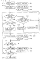
- FIG. 7 is a flowchart showing the operation to reduce standby power, in which the operations of the control substrate 307 are shown mainly.
- blocks connected to blocks showing the steps, by broken lines are components that are controlled or power supplied/cut in that step.
- step S11 the power source is turned on by turning on the power source switch 301 before the operation of the control substrate 307.
- the operating power is supplied to the control substrate 307, the compressor driver 31a, and the motor 321.
- the operating power is supplied to the fan driver 31b through the diode bridge 312 and the filter 313.
- step S12 communication (shown by an outline arrow in FIG. 6 ) is performed between the control substrate 307 and the indoor unit 5, and it is determined whether the indoor unit 5 is in operation or not in step S12.
- the determination in step S12 is repeated through a route R1.
- the process proceeds to step S13 through a route R2, and the operations of the compressor driver 31a and the fan driver 31b are commanded.
- the control commands CNTL1 and CNTL2 are given from the control substrate 307 to the compressor driver 31a and the fan driver 31b respectively to instruct operations of the compressor driver 31a and the fan driver 31b specifically.
- step S14 it is determined whether the indoor unit 5 is stopped or not. This can be determined also by the control substrate 307 based on the communication between the control substrate 307 and the indoor unit 5.
- the process proceeds to step S15, in which the operations of the compressor driver 31a and the fan driver 31b are stopped based on the control commands CNTL1 and CNTL2 from the control substrate 307.
- step S15 the operations of the compressor 309 and the fan 310 are stopped when the indoor unit 5 is stopped, whereby standby power is reduced.
- step S16 when it is determined that the power source is to be cut in step S16, the process proceeds to step S17 in which the power source is cut (the power source switch 301 is disconnected), and steps S12 to S15 are repeatedly carried out until it is determined that the power source is to be cut.
- the power supplied to the compressor driver 31a and the fan driver 31b is not needed. Thus, since this power is consumed as the standby power, the power to the compressor driver 31a and the fan driver 31b is to be also cut while the indoor unit 5 is stopped.
- step S16 is omitted in the technique shown in FIGS. 6 and 7 , so that the power supply to the compressor driver 31a and the fan driver 31b is just cut in step S17.
- the present invention was made in view of the above trade-off, and it is an object of the present invention to save power of a second control circuit when the second control circuit drives a load under the control of a first control circuit.
- a first aspect of the invention relates to the device for driving a load comprising first and second motors in an outdoor unit of an air conditioner, as defined in claim 1.
- a second aspect of the invention relates to a method of controlling a device for driving a load comprising first and second motors in an outdoor unit of an air conditioner, as defined in claim 5.
- the operating power to the second control circuit is supplied/cut based on the connection/disconnection of the first control switch, power saving can be implemented while the operating power is kept supplied to the first control circuit.
- the cooling medium can be compressed by the second compressor to some extent.
- the power supply to the inverter circuit is cut when the load becomes abnormal regardless of the power saving operation, and the abnormal situation is managed.
- the power saving can be implemented while the operating power is kept supplied to the first control circuit.
- the load driving device in the present invention when an abnormality in pressure occurs in the first compressor, the power supply to the inverter circuit is cut and the abnormal pressure of the cooling medium is managed.
- FIG. 1 is a circuit diagram illustrating the constitution of an embodiment of the present invention. The same reference numerals are allotted to the same components in the constitutions shown in FIGS. 1 and 6 .
- a control switch 305 that is connected to the output side of a power source switch 301 and performs connection/disconnection based on a switching command WP is provided and the switching command WP is outputted from a control substrate 307.
- control switch 305 exists between a noise filter 33 and a power source input 311 in a compressor driver 31a to supply/cut power to the compressor driver 31a.
- power source lines of a neutral point N and an S phase are used as a power source line group L2 connected to the power source input 311 in the compressor driver 31a, and that the connection/disconnection of the power source line of the S phase, which is one of the power source line group L2 is implemented by the control switch 305 in the constitution according to the present embodiment.
- the power source lines of an R phase and the neutral point N may also be used in the present embodiment.
- a control switch 304 is interposed in the S-phase power source line, and connecting/disconnecting thereof is controlled by the switching command WP.
- the control switches 304 and 305 are interposed in the S-phase power source line between a three-phase power source 41 and the compressor driver 31a, and every connecting/disconnecting thereof is controlled by the switching command WP similarly. Therefore, they can be put together as one control switch on the side closer to the three-phase power source 41 than splitting into the power source line groups L1 and L2.
- the power source input 311 supplies power to a microprocessor 316, and the microprocessor 316 generates a switching command T based on a switching control command CNTL1.
- the microprocessor 316 outputs the switching command T to a switching circuit 314 to control the switching operation thereof and functions as an inverter control circuit for controlling an inverter circuit including the switching circuit 314.
- a switching control command CNTL2 goes through the compressor driver 31a but it just passes through it substantially.
- the microprocessor 316 is shown including a rectification circuit and a constant-voltage circuit required for its operation.
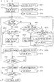
- FIG. 2 is a flowchart showing the operation to reduce standby power in the present embodiment, in which step S11 in the flowchart shown in FIG. 7 is separated into steps Slla and Sllb, and step S12 is replaced with step S22A.
- the power source switch 301 is conducted first in step S11a. At this time, the control switches 304 and 305 are not connected, and the power is not supplied to the compressor driver 31a and a fan driver 31b.
- step S11a When step S11a is carried out, operating power is supplied to a control substrate 307 and the control substrate 307 communicates with an indoor unit 5 (as shown by an outline arrow in FIG. 1 ). Then, the process proceeds to step S11b in which the power is supplied to the compressor driver 31a and the fan driver 31b. More specifically, the control signal WP is asserted, and the control switches 304 and 305 are switched from the disconnection state to the connection state. Being the control switch 305 connected, the operating power of the compressor driver 31a is supplied from the power source line group L2 to the power source input 311. Accordingly, the operating power of the fan driver 31b is supplied from a power source line group L3.
- a control switch 303 is connected in general, and together with the control switch 304, the R-phase, S-phase and T-phase powers are supplied from the power source line group L1 to the compressor driver 31a. Then, the process proceeds to step S22A.
- Step S22A includes steps S220 to S225.
- step S220 it is determined whether the indoor unit 5 is in operation or not as in step S12.
- step S224 it is determined whether the operating power to the compressor driver 31a and accordingly the fan driver 31b is cut or not in step S224.
- the operating power is supplied in step S225 (connection in the control switches 304 and 305 by asserting the control signal WP).
- step S225 is not carried out, and the process proceeds from step S224 to step S13.
- the operations in steps S13 to S16 have been already described.
- step S11b After step S11b is carried out, under the condition where a predetermined condition is satisfied, the control signal WP is negated to disconnect the control switches 304 and 305, and the power driving a motor 322, the operating power of the compressor driver 31a itself, and the operating power of the fan driver 31b are cut (in S222).
- the process proceeds to step S13 in which the compressor driver 31a and the fan driver 31b drive the motors 322 and 323 to drive a compressor 309 and a fan 310 based on the control commands CNTL1 and CNTL2.
- the case where it is determined that the above predetermined condition is satisfied includes a case where the indoor unit 5 is not in operation (S220) and air conditioning is selected in a predetermined setting throughout a first time (ten minutes, for example) after the step S11b.
- This predetermined setting is exemplified for the following cases (i) to (iii):
- step S221 the air conditioning is not set in one of the above cases (i), (ii), and (iii), or even when it is set in one of them, in the case where the period thereof is shorter than the first time.
- step S223 it is determined whether a second time (twenty minutes, for example) has elapsed after step S11b.
- a second time for example
- the process returns to step S220. Meanwhile, when the second time has elapsed, the process proceeds to step S222 in which the power for driving the motor 322, the operating power of the compressor driver 31a itself, and the operating power of the fan driver 31b are cut.
- the second time is longer than the first time. This is because when the second time is equal to the first time or shorter, even when the air conditioning is set in one of the above cases (i), (ii), and (iii) in step S221, it is not determined whether the setting is continued for the first time or not.
- step S222 when the power for driving the motor 322, the operating power of the compressor driver 31a itself, and the operating power of the fan driver 31b are cut in step S222, the process returns to step S220. Then, it is determined whether the indoor unit 5 is in operation or not again.
- step S225 the process proceeds to step S225 through step S224, in which the power for driving the motor 322, the operating power of the compressor driver 31a itself, and the operating power of the fan driver 31b are supplied.
- steps S221 to S223 for the power saving are carried out again.
- the power for driving the motor 322 is supplied/cut by the connection/disconnection of the control switch 304, and the operating power of the compressor driver 31a itself and the operating power of the fan driver 31b are supplied/cut by the connection/disconnection of the control switch 305.
- the power saving can be implemented.
- the operating power can be supplied to the control substrate 307 again by asserting the switching command WP.
- the operation control of the control switch 305 based on the switching command WP is shown by a broken line in FIG. 1 .
- the control switch 304 is a preferable component in view of the power saving of the power for driving the motor 322, and the control switch 305 is a preferable component in view of the power saving of the operating power of the compressor driver 31a itself (and the operating power of the fan driver 31) required when the motor 322 is driven.
- the power for driving the motor 322 is transformed by the inverter circuit in the compressor driver 31a. Therefore, one or both of the control switches 304 and 305 can be regarded as the preferable component in view of the power saving of the power supplied to the compressor driver 31a.
- control switches 302 and 303 are provided, and they are disconnected when an abnormal pressure signal HPS is asserted. According to the above operation, when an abnormality in pressure occurs in the compressors 308 and 309, the power supply to the inverter circuit is cut, and the abnormal situation is managed regardless of the power saving.
- the operation control of the control switches 302 and 303 by the abnormal pressure signal HPS is shown by a dotted line.
- the control switch 302 When the abnormal pressure signal HPS is asserted, the control switch 302 is also disconnected, the power to the motor 321 is cut and the compressor 308 is stopped. When any one of an abnormal pressure signal SHP1 from the compressor 308 and an abnormal pressure signal SHP2 from the compressor 309 is asserted, then the abnormal pressure signal HPS is asserted. Therefore, even when an abnormality occurs in the compressor 308, not only the control switch 302 but also the control switch 303 are disconnected to stop the compressor 309. As a matter of course, the compressor 308 is not necessarily provided in the present invention.
- the present invention can be applied not only to the case where the three-phase power source 41 has the neutral point N, but also to the case where the three-phase power source has no neutral point, keeping the constitution of the compressor driver 31a.
- the compressor 308 driven by the motor 321 is provided, even when the control switch 305 is disconnected and the compressor 309 is stopped to carry out the power saving, the cooling medium can be compressed by the compressor 308 to some extent.
- an outdoor unit having the compressors 308 and 309, the motors 321 and 322 for driving those, the control substrate 307 and the compressor driver 31a is preferable from the perspective that it can be in operation while saving the power.
- the fan driver 31b, the motor 323, and the fan 310 are preferably provided.
- step S222 all the power supplies to the compressor driver 31a may not cut but at least part of them may be cut. More specifically, for instance, the operating power of the compressor driver 31a itself may be cut by the switch 305 alone without cutting the power for driving the motor 322.
- FIG. 3 is a circuit diagram illustrating the constitution of such variation.
- the control switch 304 is shorted from the constitution shown in FIG. 1 , and a wiring group L1 is not cut by a switching command WP.
- the switching command WP only controls the switching of a control switch 305.
- a wiring group L3 is drawn from a side further from the power source input 311 than the control switch 305, and the supply/cut of the power to the wiring group L3 is depend on the switching of the control switch 305.
- the wiring group L3 may be drawn from a part closer to the power source input 311 than the controls witch 305, and the supply/cut of the power to the wiring group L3 may not depend on the switching of the control switch 305.
- a compressor driver 31a and a fan driver 31b may be mounted on the same substrate as a control substrate 307.
- the operation along the flowchart shown in FIG. 2 may be performed for the constitution shown in FIG. 3 .
- the operation along the following flowchart may be performed therefor.
- FIG. 4 is a flowchart showing the operations to reduce power in the constitution shown in FIG. 3 , in which step S22A in the flowchart shown in FIG. 2 is replaced with step S22B.
- step S220 of step S22A is replaced with step S226, and step S223 is removed. More specifically, unless it is determined that ten minutes have elapsed under a predetermined setting in step S221, the process returns to step S226.
- step S226 similar to step S221, it is determined whether the predetermined setting is made or not.
- the predetermined setting in these steps employs the setting that an inverter circuit is not controlled. Thus, it is determined whether a time during which the inverter circuit is not controlled has continued more than ten minutes or not in steps S221 and S226. When the determination is affirmative, the process proceeds to step S222 and when the determination is negative, the process proceeds to step S224.
- step S222 shown in FIG. 4 Since the control switch 304 is not provided in FIG. 3 , the power supply to a switching circuit 306 of a fan driver 31b is not cut in step S222 shown in FIG. 4 . Thus, the power supply cut of the fan driver 31b is not shown in step S222 shown in FIG. 4 unlike step S222 shown in FIG. 3 . Although the power supply to the wiring group L3 is cut, the power source to the wiring group L3 may not be cut as described above.
- the setting that the inverter circuit is not controlled includes the following cases:
- step S226 When the setting is contrary to any one of the above cases (iv) to (vi), the process proceeds from step S226 to step S224.
- FIG. 5 is a circuit diagram illustrating the case where the constitution shown in FIG. 3 includes a single-phase power source.
- the three-phase power source 41 is replaced with a single-phase power source 41, the power source switch 301, the control switch 302, and the motor 321 are replaced with those for the single phase.
- a wiring group L2 does not contain three lines but two lines.
- the indoor unit 5 may communicate with the microprocessor 316 through the control substrate 307. In this case, for example, it is determined whether the communication is correct or not appropriately. However, it is to be noted that this determination is not made when the control switch 305 is disconnected in step S222 shown in FIGS. 2 and 4 . This is because the microprocessor 316 is not in operation in that case. Thus, that determination is made after step S225, and it is preferable that the above communication is reattempted from the initial operation, for example, the operation when the power source is turned on.
Landscapes
- Engineering & Computer Science (AREA)
- Mechanical Engineering (AREA)
- General Engineering & Computer Science (AREA)
- Chemical & Material Sciences (AREA)
- Combustion & Propulsion (AREA)
- Physics & Mathematics (AREA)
- Fuzzy Systems (AREA)
- Mathematical Physics (AREA)
- Signal Processing (AREA)
- Thermal Sciences (AREA)
- Power Engineering (AREA)
- Air Conditioning Control Device (AREA)
Claims (12)
- Vorrichtung zum Antreiben einer Last umfassend erste und zweite Motoren (322, 323) in einer Außeneinheit einer Klimaanlage, wobei der erste Motor (322) einen ersten Kompressor (309) in der Außeneinheit antreibt und der erste Kompressor ein Kühlmedium komprimiert, wobei die Vorrichtung umfasst:einen Energiequellenschalter (301), der eine Eingangsseite aufweist, die mit einer Energiequelle (41) und einer Ausgangsseite verbunden ist;eine Wechselrichterschaltung (312, 313, 314), die eine Diodenbrücke (312) beinhaltet und eine erste Umschaltschaltung (314), die eine von der Diodenbrücke (312) ausgegebene Gleichspannung schaltet und die Spannung an den ersten Motor (322) abgibt, der von der Wechselrichterschaltung (312, 313, 314) mit Energie versorgt wird;eine erste Steuerschaltung (307), die mit der Ausgangsseite des Energiequellenschalters (301) verbunden ist und bei Verbinden mit dem Energiequellenschalter (301) mit Betriebsenergie versorgt wird;eine zweite Steuerschaltung (31a), die die Wechselrichterschaltung (312, 313, 314) beinhaltet, die die dem ersten Motor (322) zuzuführende Energie aus der von der Energiequelle (41) zugeführten Energie erzeugt,einen zweiten Steuerschalter (303), der zwischen dem Energiequellenschalter (301) und der Wechselrichterschaltung (312, 313, 314) angeordnet und entsprechend der Normalität/Anormalität des ersten Motors (322) verbunden/getrennt ist;eine dritte Steuerschaltung (31b), die eine zweite Umschaltschaltung (306) aufweist, die die Gleichspannung der Wechselrichterschaltung (312, 313, 314) schaltet und die Spannung an den zweiten Motor (323) abgibt, um den zweiten Motor (323) mit Betriebsenergie zu versorgen, und den zweiten Motor (323) basierend auf einem zweiten Steuerbefehl (CNTL2) von der ersten Steuerschaltung (307) antreibt; wobeidie erste Steuerschaltung (307) einen zweiten Schaltbefehl (HPS) erzeugt, um einen zweiten Steuerschalter zu trennen, wenn eine Anormalität im Druck in dem ersten Kompressor (309) auftritt,ein erster Steuerschalter (304, 305) mit der Ausgangsseite des Energiequellenschalters (301) verbunden und unter einem ersten Schaltbefehl (WP) von der ersten Steuerschaltung (307) verbunden/getrennt ist; wobeidie zweite Steuerschaltung (31a) beim Verbinden von beiden, dem Energiequellenschalter (301) und dem ersten Steuerschalter (304, 305) mit Energie versorgt wird und den ersten Motor (322) unter einem ersten Steuerbefehl (CNTL1) von der ersten Steuerschaltung (307) antreibt.
- Außeneinheit einer Klimaanlage, umfassend:die Vorrichtung nach Anspruch 1;den ersten Motor (322);den zweiten Motor (323); undden ersten Kompressor (309).
- Vorrichtung nach Anspruch 1, wobei
die zweite Steuerschaltung (31a) beinhaltet:eine Wechselrichtersteuerschaltung (316), die den Betrieb der Wechselrichterschaltung (312, 313, 314) steuert; und wobeider erste Steuerschalter (304, 305) einen Schalter (305) zum Versorgen/- Unterbrechen der Wechselrichtersteuerschaltung (316) beinhaltet. - Vorrichtung nach Anspruch 3, wobei
der erste Steuerschalter (304, 305) einen Schalter (304) zum Versorgen/- Unterbrechen von Energie an die Wechselrichterschaltung (312, 313, 314) beinhaltet. - Verfahren zum Antreiben einer Last umfassend erste und zweite Motoren in einer Außeneinheit einer Klimaanlage, wobei der erste Motor (322) einen ersten Kompressor (309) antreibt und der erste Kompressor (309) ein Kühlmedium komprimiert, wobei das Verfahren umfasst:(a) einen ersten Schritt (S11a) des Versorgens einer ersten Steuerschaltung (307) mit Betriebsenergie;(b) einen zweiten Schritt (Sllb) des Startens der Energieversorgung einer zweiten Steuerschaltung (31a), die den ersten Motor (322) nach dem ersten Schritt (a) antreibt; und(c) einen dritten Schritt (S222) des Unterbrechens wenigstens eines Teils der Energieversorgungen der zweiten Steuerschaltung (31a) in einem Zustand, in dem eine vorbestimmte Bedingung (S220, S221, S223) nach dem zweiten Schritt (b) erfüllt ist;(d) einen vierten Schritt (S13) des Antreibens des ersten Motors (322) durch die zweite Steuerschaltung (31a), basierend auf einem ersten Steuerbefehl (CNTL1), der von der ersten Steuerschaltung (307) in einem Zustand erhalten wird, in dem die vorbestimmte Bedingung nicht erfüllt ist, nach dem zweiten Schritt (b).
- Verfahren nach Anspruch 5, wobei
die zweite Steuerschaltung (31a) eine Wechselrichterschaltung (312, 313, 314) beinhaltet, die Energie erzeugt, die der ersten Motorlast (322) unter dem ersten Steuerbefehl (CNTL1) zuzuführen ist,
der erste Motor (322) von der Wechselrichterschaltung (312, 313, 314) mit Energie versorgt wird; wobei
bestimmt wird, dass die vorbestimmte Bedingung in einem Fall erfüllt ist, in dem eine Inneneinheit (5) einer Klimaanlage, die eine Klimatisierung unter Verwendung des Kühlmediums durchführt, nicht in Betrieb (S220) ist und die Klimatisierung in einer vorbestimmten Einstellung während eines Zeitraums ausgewählt wird, bei dem eine erste Zeit vergeht, nach dem zweiten Schritt (b) (S221). - Verfahren nach Anspruch 6, wobei
die vorbestimmte Einstellung einen Fall beinhaltet, bei dem sich die Klimaanlage in einem Blasbetrieb befindet. - Verfahren nach Anspruch 6, wobei
die vorbestimmte Einstellung einen Fall beinhaltet, bei dem sich die Klimaanlage in einem Kühlbetrieb in einem Zustand befindet, in dem eine Umgebungstemperatur niedriger als eine erste Temperatur ist. - Verfahren nach Anspruch 6, wobei
die vorbestimmte Einstellung einen Fall beinhaltet, bei dem sich die Klimaanlage in einem Erwärmungsbetrieb in einem Zustand befindet, in dem eine Umgebungstemperatur höher als eine zweite Temperatur ist. - Verfahren nach Anspruch 6, wobei
bestimmt wird, dass die vorbestimmte Bedingung in einem Fall erfüllt ist, in dem die Inneneinheit (5) nicht in Betrieb (S220) ist und auch eine zweite Zeit, die länger als die erste Zeit ist, ab dem zweiten Schritt (b) (S223) vergangen ist. - Verfahren nach Anspruch 5, wobei
die zweite Steuerschaltung (31a) beinhaltet:eine Wechselrichterschaltung (312, 313, 314), die unter dem ersten Steuerbefehl (CNTL1) dem ersten Motor (322) zuzuführende Energie erzeugt; undeine Wechselrichtersteuerschaltung (316), die den Betrieb der Wechselrichterschaltung (312, 313, 314) steuert, undden ersten Motor (322), der von der Wechselrichterschaltung (312, 313, 314) mit Energie versorgt wird; wobeibestimmt wird, dass die vorbestimmte Bedingung in einem Fall erfüllt ist, in dem eine Zeit, während der die Wechselrichterschaltung (312, 313, 314) nicht gesteuert wird, für einen vorbestimmten Zeitraum oder mehr (S226, S221) fortwährt, unddie Energieversorgung der Wechselrichtersteuerschaltung (316) unterbrochen wird, während die Energieversorgung zur Wechselrichterschaltung (312, 313, 314) in dem dritten Schritt (c) beibehalten wird. - Verfahren zum Antreiben der Last nach einem der Ansprüche 5 bis 11, weiter umfassend:
(e) einen fünften Schritt (S15) des Anhaltens des Antriebs der Last, die von der zweiten Steuerschaltung (31a) angetrieben wird, wobei der Betrieb der Inneneinheit (5) nach dem vierten Schritt (d) angehalten (S14) wird, wobei
der dritte Schritt (c) oder der vierte Schritt (d) erneut ausgeführt wird, außer in einem Fall, in dem beide der Versorgungen von Betriebsenergie an die erste Steuerschaltung (101) und die Betriebsenergie an die zweite Steuerschaltung (31a) nach dem fünften Schritt (e) angehalten (S16, S17) werden.
Applications Claiming Priority (3)
| Application Number | Priority Date | Filing Date | Title |
|---|---|---|---|
| JP2006062134 | 2006-03-08 | ||
| JP2006233758A JP4075951B2 (ja) | 2006-03-08 | 2006-08-30 | 負荷駆動装置及び空気調和機の室外機並びに負荷の駆動方法 |
| PCT/JP2007/054022 WO2007102423A1 (ja) | 2006-03-08 | 2007-03-02 | 負荷駆動装置及び空気調和機の室外機並びに負荷の駆動方法 |
Publications (3)
| Publication Number | Publication Date |
|---|---|
| EP1995529A1 EP1995529A1 (de) | 2008-11-26 |
| EP1995529A4 EP1995529A4 (de) | 2015-01-21 |
| EP1995529B1 true EP1995529B1 (de) | 2018-12-19 |
Family
ID=38474854
Family Applications (1)
| Application Number | Title | Priority Date | Filing Date |
|---|---|---|---|
| EP07737670.5A Active EP1995529B1 (de) | 2006-03-08 | 2007-03-02 | Lastantriebsgerät für eine ausseneinheit einer klimaanlage sowie lastantriebsverfahren |
Country Status (8)
| Country | Link |
|---|---|
| US (1) | US8109103B2 (de) |
| EP (1) | EP1995529B1 (de) |
| JP (1) | JP4075951B2 (de) |
| KR (1) | KR101027613B1 (de) |
| CN (1) | CN101395430B (de) |
| AU (1) | AU2007223535B2 (de) |
| ES (1) | ES2715601T3 (de) |
| WO (1) | WO2007102423A1 (de) |
Families Citing this family (17)
| Publication number | Priority date | Publication date | Assignee | Title |
|---|---|---|---|---|
| DE102008046040B4 (de) * | 2008-09-05 | 2012-03-15 | Siemens Medical Instruments Pte. Ltd. | Verfahren zum Betrieb einer Hörvorrichtung mit Richtwirkung und zugehörige Hörvorrichtung |
| JP5007764B2 (ja) * | 2010-09-22 | 2012-08-22 | ダイキン工業株式会社 | モータ駆動システム及びモータシステム |
| BRPI1100270B1 (pt) * | 2011-02-25 | 2019-03-19 | Embraco Indústria De Compressores E Soluções Em Refrigeração Ltda | Sistema e método de controle eletrônico de um compressor de capacidade variável |
| FR2976654B1 (fr) * | 2011-06-15 | 2013-07-12 | Voltalis | Dispositif de chauffage, ventilation et/ou climatisation a gestion d'alimentation ciblee. |
| JP5454596B2 (ja) * | 2012-02-08 | 2014-03-26 | ダイキン工業株式会社 | 電源制御装置 |
| JP5421433B2 (ja) * | 2012-06-25 | 2014-02-19 | ファナック株式会社 | 制御電源の消費電力を停電時に低減するモータ制御装置 |
| JP5984732B2 (ja) * | 2013-04-09 | 2016-09-06 | 三菱電機株式会社 | 空気調和機 |
| JP6210167B2 (ja) * | 2014-10-24 | 2017-10-11 | 三菱電機株式会社 | 除湿機の制御装置 |
| JP6464903B2 (ja) * | 2015-04-16 | 2019-02-06 | ダイキン工業株式会社 | 空気調和機のインバータ駆動装置 |
| JP6393287B2 (ja) | 2016-01-27 | 2018-09-19 | 日立ジョンソンコントロールズ空調株式会社 | 空気調和機の室外機 |
| CN111954785B (zh) * | 2018-04-18 | 2021-11-02 | 三菱电机株式会社 | 控制基板以及空调机的室内机 |
| JP7390122B2 (ja) * | 2019-07-18 | 2023-12-01 | 日立ジョンソンコントロールズ空調株式会社 | 空気調和システム及び異常検出システム |
| JP7356832B2 (ja) * | 2019-07-18 | 2023-10-05 | 日立ジョンソンコントロールズ空調株式会社 | 空気調和システム及び異常検出システム |
| JP7148807B2 (ja) * | 2019-07-31 | 2022-10-06 | ダイキン工業株式会社 | 電算機室用空気調和装置 |
| US12348166B2 (en) * | 2021-02-17 | 2025-07-01 | Mitsubishi Electric Corporation | Motor drive apparatus, refrigeration cycle apparatus, air conditioner, water heater, and refrigerator |
| JP7652167B2 (ja) * | 2022-09-29 | 2025-03-27 | ニデック株式会社 | 制御装置、ポンプユニット、及び冷媒循環装置 |
| WO2024176401A1 (ja) * | 2023-02-22 | 2024-08-29 | 三菱電機株式会社 | 室外機 |
Family Cites Families (10)
| Publication number | Priority date | Publication date | Assignee | Title |
|---|---|---|---|---|
| JPH11211253A (ja) | 1998-01-28 | 1999-08-06 | Matsushita Electric Ind Co Ltd | 分離型空気調和機の制御装置 |
| JP4153586B2 (ja) | 1998-04-28 | 2008-09-24 | 東芝キヤリア株式会社 | 空気調和機 |
| JPH11325545A (ja) | 1998-05-15 | 1999-11-26 | Daikin Ind Ltd | 蓄電式空調システム |
| JP3705934B2 (ja) * | 1998-08-26 | 2005-10-12 | 株式会社リコー | モータの駆動装置 |
| JP2000205627A (ja) | 1999-01-07 | 2000-07-28 | Matsushita Electric Ind Co Ltd | 空気調和機の待機運転制御装置 |
| JP2000333365A (ja) * | 1999-05-19 | 2000-11-30 | Hitachi Ltd | 待機時電力供給システムとこれを用いた空気調和機,冷蔵庫 |
| JP3730808B2 (ja) | 1999-06-03 | 2006-01-05 | 株式会社日立製作所 | 空気調和機 |
| JP4441247B2 (ja) * | 2003-12-04 | 2010-03-31 | 三菱電機株式会社 | エレベータの制御装置 |
| KR20050055452A (ko) * | 2003-12-08 | 2005-06-13 | 엘지전자 주식회사 | 대기전력 절감 에어컨 시스템 및 그 동작방법 |
| KR100836821B1 (ko) | 2007-02-16 | 2008-06-12 | 삼성전자주식회사 | 대기전력 절감 공기조화기 시스템 및 그 동작방법 |
-
2006
- 2006-08-30 JP JP2006233758A patent/JP4075951B2/ja active Active
-
2007
- 2007-03-02 US US12/224,089 patent/US8109103B2/en active Active
- 2007-03-02 WO PCT/JP2007/054022 patent/WO2007102423A1/ja not_active Ceased
- 2007-03-02 EP EP07737670.5A patent/EP1995529B1/de active Active
- 2007-03-02 ES ES07737670T patent/ES2715601T3/es active Active
- 2007-03-02 AU AU2007223535A patent/AU2007223535B2/en active Active
- 2007-03-02 KR KR1020087021717A patent/KR101027613B1/ko active Active
- 2007-03-02 CN CN2007800074747A patent/CN101395430B/zh active Active
Non-Patent Citations (1)
| Title |
|---|
| None * |
Also Published As
| Publication number | Publication date |
|---|---|
| JP2007271248A (ja) | 2007-10-18 |
| WO2007102423A1 (ja) | 2007-09-13 |
| AU2007223535B2 (en) | 2010-08-19 |
| US20090007579A1 (en) | 2009-01-08 |
| KR101027613B1 (ko) | 2011-04-06 |
| US8109103B2 (en) | 2012-02-07 |
| KR20080100234A (ko) | 2008-11-14 |
| EP1995529A1 (de) | 2008-11-26 |
| ES2715601T3 (es) | 2019-06-05 |
| EP1995529A4 (de) | 2015-01-21 |
| AU2007223535A1 (en) | 2007-09-13 |
| CN101395430A (zh) | 2009-03-25 |
| JP4075951B2 (ja) | 2008-04-16 |
| CN101395430B (zh) | 2010-08-11 |
Similar Documents
| Publication | Publication Date | Title |
|---|---|---|
| AU2007223535B2 (en) | Load driving device, outdoor unit of air conditioner, and driving method of load | |
| EP1426620B1 (de) | Geschwindigkeitsregelung von mehreren Motoren | |
| US20100045105A1 (en) | Integrated multiple power conversion system for transport refrigeration units | |
| EP2481998A1 (de) | Klimaanlage | |
| CN101326408A (zh) | 具有变速驱动器的制冷剂系统 | |
| CN104141604A (zh) | 空压机专用变频器及空压机变频驱动控制系统 | |
| US20110203779A1 (en) | Uninterruptible cooling system and apparatus | |
| WO2009100657A1 (en) | Uninterruptible cooling system and apparatus | |
| JP2002081712A (ja) | 空気調和機 | |
| CN101512889B (zh) | 操作电动机系统的方法和电动机系统 | |
| KR101596680B1 (ko) | 공기조화기 및 그 제어방법 | |
| KR100324744B1 (ko) | 대기전력 저감장치 및 방법 | |
| GB2617988A (en) | Air conditioner | |
| KR20070039764A (ko) | 유니터리 공기조화기 | |
| JP2000002188A (ja) | 空気調和機の制御装置 | |
| KR102847066B1 (ko) | 전동차용 냉방장치 및 이의 압축기 구동방법 | |
| KR20190060208A (ko) | 대기 전력 제어 장치 | |
| WO2024176424A1 (ja) | 電動機駆動装置及び空気調和機 | |
| WO2022218266A1 (zh) | 控制器、空调及高压保护电路 | |
| US11588427B2 (en) | Motor drive device and air conditioner | |
| JP2003279185A (ja) | 極低温冷凍機 | |
| CN101087065A (zh) | 空调压缩机保护装置及其保护方法 | |
| KR20010037410A (ko) | 인버터 공기조화기의 운전주파수 가변제어방법 | |
| JP2004263649A (ja) | 圧縮空気装置制御システム | |
| JPH07270004A (ja) | 空気調和機の制御装置 |
Legal Events
| Date | Code | Title | Description |
|---|---|---|---|
| PUAI | Public reference made under article 153(3) epc to a published international application that has entered the european phase |
Free format text: ORIGINAL CODE: 0009012 |
|
| 17P | Request for examination filed |
Effective date: 20080814 |
|
| AK | Designated contracting states |
Kind code of ref document: A1 Designated state(s): AT BE BG CH CY CZ DE DK EE ES FI FR GB GR HU IE IS IT LI LT LU LV MC MT NL PL PT RO SE SI SK TR |
|
| DAX | Request for extension of the european patent (deleted) | ||
| A4 | Supplementary search report drawn up and despatched |
Effective date: 20141223 |
|
| RIC1 | Information provided on ipc code assigned before grant |
Ipc: H02P 6/00 20060101ALI20141217BHEP Ipc: F24F 11/00 20060101ALI20141217BHEP Ipc: F24F 11/02 20060101AFI20141217BHEP Ipc: F25B 49/02 20060101ALI20141217BHEP |
|
| STAA | Information on the status of an ep patent application or granted ep patent |
Free format text: STATUS: EXAMINATION IS IN PROGRESS |
|
| 17Q | First examination report despatched |
Effective date: 20170426 |
|
| GRAP | Despatch of communication of intention to grant a patent |
Free format text: ORIGINAL CODE: EPIDOSNIGR1 |
|
| STAA | Information on the status of an ep patent application or granted ep patent |
Free format text: STATUS: GRANT OF PATENT IS INTENDED |
|
| RIC1 | Information provided on ipc code assigned before grant |
Ipc: F25B 49/02 20060101ALI20180420BHEP Ipc: H02P 6/00 20060101AFI20180420BHEP Ipc: F24F 11/00 20060101ALI20180420BHEP |
|
| RIC1 | Information provided on ipc code assigned before grant |
Ipc: F25B 49/02 20060101ALI20180517BHEP Ipc: F24F 11/62 20180101ALI20180517BHEP Ipc: H02P 6/00 20060101AFI20180517BHEP Ipc: F24F 11/00 20060101ALI20180517BHEP |
|
| INTG | Intention to grant announced |
Effective date: 20180530 |
|
| GRAJ | Information related to disapproval of communication of intention to grant by the applicant or resumption of examination proceedings by the epo deleted |
Free format text: ORIGINAL CODE: EPIDOSDIGR1 |
|
| STAA | Information on the status of an ep patent application or granted ep patent |
Free format text: STATUS: EXAMINATION IS IN PROGRESS |
|
| REG | Reference to a national code |
Ref country code: DE Ref legal event code: R079 Ref document number: 602007057163 Country of ref document: DE Free format text: PREVIOUS MAIN CLASS: F24F0011020000 Ipc: H02P0006000000 |
|
| INTC | Intention to grant announced (deleted) | ||
| RIC1 | Information provided on ipc code assigned before grant |
Ipc: F24F 11/00 20060101ALI20180918BHEP Ipc: H02P 6/00 20060101AFI20180918BHEP Ipc: F24F 11/62 20180101ALI20180918BHEP Ipc: F24F 11/30 20180101ALI20180918BHEP Ipc: F25B 49/02 20060101ALI20180918BHEP |
|
| GRAR | Information related to intention to grant a patent recorded |
Free format text: ORIGINAL CODE: EPIDOSNIGR71 |
|
| GRAS | Grant fee paid |
Free format text: ORIGINAL CODE: EPIDOSNIGR3 |
|
| STAA | Information on the status of an ep patent application or granted ep patent |
Free format text: STATUS: GRANT OF PATENT IS INTENDED |
|
| GRAA | (expected) grant |
Free format text: ORIGINAL CODE: 0009210 |
|
| STAA | Information on the status of an ep patent application or granted ep patent |
Free format text: STATUS: THE PATENT HAS BEEN GRANTED |
|
| AK | Designated contracting states |
Kind code of ref document: B1 Designated state(s): AT BE BG CH CY CZ DE DK EE ES FI FR GB GR HU IE IS IT LI LT LU LV MC MT NL PL PT RO SE SI SK TR |
|
| INTG | Intention to grant announced |
Effective date: 20181112 |
|
| REG | Reference to a national code |
Ref country code: GB Ref legal event code: FG4D |
|
| REG | Reference to a national code |
Ref country code: CH Ref legal event code: EP |
|
| REG | Reference to a national code |
Ref country code: IE Ref legal event code: FG4D |
|
| REG | Reference to a national code |
Ref country code: DE Ref legal event code: R096 Ref document number: 602007057163 Country of ref document: DE |
|
| REG | Reference to a national code |
Ref country code: AT Ref legal event code: REF Ref document number: 1079759 Country of ref document: AT Kind code of ref document: T Effective date: 20190115 |
|
| REG | Reference to a national code |
Ref country code: CH Ref legal event code: PK Free format text: BERICHTIGUNGEN |
|
| RIC2 | Information provided on ipc code assigned after grant |
Ipc: F24F 11/62 20180101ALI20180918BHEP Ipc: F24F 11/00 20180101ALI20180918BHEP Ipc: H02P 6/00 20160101AFI20180918BHEP Ipc: F24F 11/30 20180101ALI20180918BHEP Ipc: F25B 49/02 20060101ALI20180918BHEP |
|
| REG | Reference to a national code |
Ref country code: NL Ref legal event code: MP Effective date: 20181219 |
|
| PG25 | Lapsed in a contracting state [announced via postgrant information from national office to epo] |
Ref country code: BG Free format text: LAPSE BECAUSE OF FAILURE TO SUBMIT A TRANSLATION OF THE DESCRIPTION OR TO PAY THE FEE WITHIN THE PRESCRIBED TIME-LIMIT Effective date: 20190319 Ref country code: FI Free format text: LAPSE BECAUSE OF FAILURE TO SUBMIT A TRANSLATION OF THE DESCRIPTION OR TO PAY THE FEE WITHIN THE PRESCRIBED TIME-LIMIT Effective date: 20181219 Ref country code: LT Free format text: LAPSE BECAUSE OF FAILURE TO SUBMIT A TRANSLATION OF THE DESCRIPTION OR TO PAY THE FEE WITHIN THE PRESCRIBED TIME-LIMIT Effective date: 20181219 Ref country code: LV Free format text: LAPSE BECAUSE OF FAILURE TO SUBMIT A TRANSLATION OF THE DESCRIPTION OR TO PAY THE FEE WITHIN THE PRESCRIBED TIME-LIMIT Effective date: 20181219 |
|
| REG | Reference to a national code |
Ref country code: LT Ref legal event code: MG4D |
|
| REG | Reference to a national code |
Ref country code: AT Ref legal event code: MK05 Ref document number: 1079759 Country of ref document: AT Kind code of ref document: T Effective date: 20181219 |
|
| PG25 | Lapsed in a contracting state [announced via postgrant information from national office to epo] |
Ref country code: GR Free format text: LAPSE BECAUSE OF FAILURE TO SUBMIT A TRANSLATION OF THE DESCRIPTION OR TO PAY THE FEE WITHIN THE PRESCRIBED TIME-LIMIT Effective date: 20190320 Ref country code: SE Free format text: LAPSE BECAUSE OF FAILURE TO SUBMIT A TRANSLATION OF THE DESCRIPTION OR TO PAY THE FEE WITHIN THE PRESCRIBED TIME-LIMIT Effective date: 20181219 |
|
| REG | Reference to a national code |
Ref country code: ES Ref legal event code: FG2A Ref document number: 2715601 Country of ref document: ES Kind code of ref document: T3 Effective date: 20190605 |
|
| PG25 | Lapsed in a contracting state [announced via postgrant information from national office to epo] |
Ref country code: NL Free format text: LAPSE BECAUSE OF FAILURE TO SUBMIT A TRANSLATION OF THE DESCRIPTION OR TO PAY THE FEE WITHIN THE PRESCRIBED TIME-LIMIT Effective date: 20181219 |
|
| PG25 | Lapsed in a contracting state [announced via postgrant information from national office to epo] |
Ref country code: PT Free format text: LAPSE BECAUSE OF FAILURE TO SUBMIT A TRANSLATION OF THE DESCRIPTION OR TO PAY THE FEE WITHIN THE PRESCRIBED TIME-LIMIT Effective date: 20190419 Ref country code: PL Free format text: LAPSE BECAUSE OF FAILURE TO SUBMIT A TRANSLATION OF THE DESCRIPTION OR TO PAY THE FEE WITHIN THE PRESCRIBED TIME-LIMIT Effective date: 20181219 Ref country code: CZ Free format text: LAPSE BECAUSE OF FAILURE TO SUBMIT A TRANSLATION OF THE DESCRIPTION OR TO PAY THE FEE WITHIN THE PRESCRIBED TIME-LIMIT Effective date: 20181219 |
|
| PG25 | Lapsed in a contracting state [announced via postgrant information from national office to epo] |
Ref country code: SK Free format text: LAPSE BECAUSE OF FAILURE TO SUBMIT A TRANSLATION OF THE DESCRIPTION OR TO PAY THE FEE WITHIN THE PRESCRIBED TIME-LIMIT Effective date: 20181219 Ref country code: RO Free format text: LAPSE BECAUSE OF FAILURE TO SUBMIT A TRANSLATION OF THE DESCRIPTION OR TO PAY THE FEE WITHIN THE PRESCRIBED TIME-LIMIT Effective date: 20181219 Ref country code: IS Free format text: LAPSE BECAUSE OF FAILURE TO SUBMIT A TRANSLATION OF THE DESCRIPTION OR TO PAY THE FEE WITHIN THE PRESCRIBED TIME-LIMIT Effective date: 20190419 Ref country code: EE Free format text: LAPSE BECAUSE OF FAILURE TO SUBMIT A TRANSLATION OF THE DESCRIPTION OR TO PAY THE FEE WITHIN THE PRESCRIBED TIME-LIMIT Effective date: 20181219 |
|
| REG | Reference to a national code |
Ref country code: DE Ref legal event code: R097 Ref document number: 602007057163 Country of ref document: DE |
|
| PLBE | No opposition filed within time limit |
Free format text: ORIGINAL CODE: 0009261 |
|
| STAA | Information on the status of an ep patent application or granted ep patent |
Free format text: STATUS: NO OPPOSITION FILED WITHIN TIME LIMIT |
|
| PG25 | Lapsed in a contracting state [announced via postgrant information from national office to epo] |
Ref country code: AT Free format text: LAPSE BECAUSE OF FAILURE TO SUBMIT A TRANSLATION OF THE DESCRIPTION OR TO PAY THE FEE WITHIN THE PRESCRIBED TIME-LIMIT Effective date: 20181219 Ref country code: DK Free format text: LAPSE BECAUSE OF FAILURE TO SUBMIT A TRANSLATION OF THE DESCRIPTION OR TO PAY THE FEE WITHIN THE PRESCRIBED TIME-LIMIT Effective date: 20181219 Ref country code: MC Free format text: LAPSE BECAUSE OF FAILURE TO SUBMIT A TRANSLATION OF THE DESCRIPTION OR TO PAY THE FEE WITHIN THE PRESCRIBED TIME-LIMIT Effective date: 20181219 |
|
| REG | Reference to a national code |
Ref country code: CH Ref legal event code: PL |
|
| 26N | No opposition filed |
Effective date: 20190920 |
|
| PG25 | Lapsed in a contracting state [announced via postgrant information from national office to epo] |
Ref country code: LU Free format text: LAPSE BECAUSE OF NON-PAYMENT OF DUE FEES Effective date: 20190302 |
|
| REG | Reference to a national code |
Ref country code: BE Ref legal event code: MM Effective date: 20190331 |
|
| PG25 | Lapsed in a contracting state [announced via postgrant information from national office to epo] |
Ref country code: IE Free format text: LAPSE BECAUSE OF NON-PAYMENT OF DUE FEES Effective date: 20190302 Ref country code: LI Free format text: LAPSE BECAUSE OF NON-PAYMENT OF DUE FEES Effective date: 20190331 Ref country code: CH Free format text: LAPSE BECAUSE OF NON-PAYMENT OF DUE FEES Effective date: 20190331 |
|
| PG25 | Lapsed in a contracting state [announced via postgrant information from national office to epo] |
Ref country code: SI Free format text: LAPSE BECAUSE OF FAILURE TO SUBMIT A TRANSLATION OF THE DESCRIPTION OR TO PAY THE FEE WITHIN THE PRESCRIBED TIME-LIMIT Effective date: 20181219 Ref country code: BE Free format text: LAPSE BECAUSE OF NON-PAYMENT OF DUE FEES Effective date: 20190331 |
|
| PG25 | Lapsed in a contracting state [announced via postgrant information from national office to epo] |
Ref country code: MT Free format text: LAPSE BECAUSE OF NON-PAYMENT OF DUE FEES Effective date: 20190302 |
|
| PG25 | Lapsed in a contracting state [announced via postgrant information from national office to epo] |
Ref country code: CY Free format text: LAPSE BECAUSE OF FAILURE TO SUBMIT A TRANSLATION OF THE DESCRIPTION OR TO PAY THE FEE WITHIN THE PRESCRIBED TIME-LIMIT Effective date: 20181219 |
|
| PG25 | Lapsed in a contracting state [announced via postgrant information from national office to epo] |
Ref country code: HU Free format text: LAPSE BECAUSE OF FAILURE TO SUBMIT A TRANSLATION OF THE DESCRIPTION OR TO PAY THE FEE WITHIN THE PRESCRIBED TIME-LIMIT; INVALID AB INITIO Effective date: 20070302 |
|
| P01 | Opt-out of the competence of the unified patent court (upc) registered |
Effective date: 20230525 |
|
| PGFP | Annual fee paid to national office [announced via postgrant information from national office to epo] |
Ref country code: FR Payment date: 20250210 Year of fee payment: 19 |
|
| PGFP | Annual fee paid to national office [announced via postgrant information from national office to epo] |
Ref country code: IT Payment date: 20250211 Year of fee payment: 19 Ref country code: GB Payment date: 20250130 Year of fee payment: 19 |
|
| PGFP | Annual fee paid to national office [announced via postgrant information from national office to epo] |
Ref country code: TR Payment date: 20250226 Year of fee payment: 19 |
|
| PGFP | Annual fee paid to national office [announced via postgrant information from national office to epo] |
Ref country code: ES Payment date: 20250403 Year of fee payment: 19 |
|
| PGFP | Annual fee paid to national office [announced via postgrant information from national office to epo] |
Ref country code: DE Payment date: 20260128 Year of fee payment: 20 |