EP1995200A2 - Method and device for operating a winding device of a textile machine which produces crosswound bobbins - Google Patents
Method and device for operating a winding device of a textile machine which produces crosswound bobbins Download PDFInfo
- Publication number
- EP1995200A2 EP1995200A2 EP08007077A EP08007077A EP1995200A2 EP 1995200 A2 EP1995200 A2 EP 1995200A2 EP 08007077 A EP08007077 A EP 08007077A EP 08007077 A EP08007077 A EP 08007077A EP 1995200 A2 EP1995200 A2 EP 1995200A2
- Authority
- EP
- European Patent Office
- Prior art keywords
- thread
- cross
- bobbin
- yarn
- wound
- Prior art date
- Legal status (The legal status is an assumption and is not a legal conclusion. Google has not performed a legal analysis and makes no representation as to the accuracy of the status listed.)
- Granted
Links
Images


Classifications
-
- B—PERFORMING OPERATIONS; TRANSPORTING
- B65—CONVEYING; PACKING; STORING; HANDLING THIN OR FILAMENTARY MATERIAL
- B65H—HANDLING THIN OR FILAMENTARY MATERIAL, e.g. SHEETS, WEBS, CABLES
- B65H54/00—Winding, coiling, or depositing filamentary material
- B65H54/02—Winding and traversing material on to reels, bobbins, tubes, or like package cores or formers
- B65H54/28—Traversing devices; Package-shaping arrangements
- B65H54/34—Traversing devices; Package-shaping arrangements for laying subsidiary winding, e.g. transfer tails
- B65H54/346—Traversing devices; Package-shaping arrangements for laying subsidiary winding, e.g. transfer tails on or outwardly of the fully wound yarn package
-
- B—PERFORMING OPERATIONS; TRANSPORTING
- B65—CONVEYING; PACKING; STORING; HANDLING THIN OR FILAMENTARY MATERIAL
- B65H—HANDLING THIN OR FILAMENTARY MATERIAL, e.g. SHEETS, WEBS, CABLES
- B65H59/00—Adjusting or controlling tension in filamentary material, e.g. for preventing snarling; Applications of tension indicators
- B65H59/10—Adjusting or controlling tension in filamentary material, e.g. for preventing snarling; Applications of tension indicators by devices acting on running material and not associated with supply or take-up devices
- B65H59/105—Adjusting or controlling tension in filamentary material, e.g. for preventing snarling; Applications of tension indicators by devices acting on running material and not associated with supply or take-up devices the material being subjected to the action of a fluid
-
- D—TEXTILES; PAPER
- D01—NATURAL OR MAN-MADE THREADS OR FIBRES; SPINNING
- D01H—SPINNING OR TWISTING
- D01H1/00—Spinning or twisting machines in which the product is wound-up continuously
- D01H1/14—Details
- D01H1/38—Arrangements for winding reserve lengths of yarn on take-up packages or spindles, e.g. transfer tails
-
- B—PERFORMING OPERATIONS; TRANSPORTING
- B65—CONVEYING; PACKING; STORING; HANDLING THIN OR FILAMENTARY MATERIAL
- B65H—HANDLING THIN OR FILAMENTARY MATERIAL, e.g. SHEETS, WEBS, CABLES
- B65H2701/00—Handled material; Storage means
- B65H2701/30—Handled filamentary material
- B65H2701/31—Textiles threads or artificial strands of filaments
Definitions
- the invention relates to a method for operating a winding apparatus of a textile machine producing cross-wound bobbins according to the preamble of claim 1 or a device according to claim 5.
- the Fadenendreserve the cross-wound bobbin is usually formed by the fact that after the completion of the bobbin first some of the cross wound wound thread windings are unwound again from the bobbin and then wound up as a parallel winding either on the bobbin surface or on the top of the cheese package again.
- a workstation traveling along the work stations of a cross-wound textile machine after completion of a cross-wound bobbin receives the thread wound on the bobbin surface with its suction nozzle, unwinds a certain amount of thread from the cross-wound bobbin and caches it in the suction nozzle.
- the yarn extending from the cross-wound bobbin to the suction nozzle is deflected by means of guiding means on the suction nozzle beyond the end face of the cross-wound bobbin and thereby conveyed into the area of a yarn guide element pivotally mounted on the creel.
- Fadenleitelement is operated to create a final thread reserve by the control unit. That is, by a shift lever arranged on the operating unit a Fadenleitkontur the Fadenleitelements in the vicinity of the gusset, which is formed by the yarn package and the bobbin, pressed and ensures that the thread is wound up as Fadenendreserve on the top of the cheese package.
- the thread between the sleeve and suction nozzle is taut because of the voltage applied to the suction nozzle of the operating unit suction flow and is wound in relatively tight windings on the sleeve.
- a bobbin change carriage which has, among other things, a suction nozzle, a bobbin drive and a spindle-like thread guiding device.
- the suction nozzle is first pivoted in the region of the cheeses and also the cross-wound bobbin rotated by the reel drive in the unwinding in this bobbin change car.
- the suction nozzle takes on a certain amount of thread accumulated on the bobbin surface thread and stores this amount of thread temporarily.
- the thread guide designed as a spindle is pivoted into the yarn strand extending between the cheese and the suction nozzle and the cheese is again rotated in the winding direction, with yarn being pulled out of the suction nozzle.
- the thread is thereby guided down from the coil surface, pulled as a chord over the cheeses flank and then fixed in parallel windings on the cheese surface.
- This spring-loaded guide rail is fixed during the winding process by a controllable locking mechanism in its rest position and, when the cheese has reached a predetermined diameter, pivoted so that the thread lifted from the thread guide the Fadenchangier immunity and on the guide bar in the direction of the coil flank arranged guide notch is displaced.
- the sliding in the guide groove thread runs in parallel windings on the cross-wound bobbin and forms, before it is separated by an associated thread cutting device, a final thread reserve.
- the present invention seeks to develop a method and apparatus that allows the creation of a cross-wound bobbin with a proper, secure Fadenendreserve already in the course of the winding process. That is, to provide a method and a device in which / can be dispensed with in the preparation of a final thread reserve on the unwinding and rewinding a thread end of a cross-wound bobbin, in particular with the help of an operating unit.
- the inventive method which is preferably used in winding stations, which have a creel for freely rotatable holding a cross-wound bobbin, a single motor driven bobbin drive roller, a motor driven, defined controllable Fadenchangier Road and a winding own filament storage device, has the advantage that the final thread reserve already at the end the "regular" winding process can be performed by the winding unit itself, that is, it does not need to be maintained until an operating unit an administrat the winding unit, unwinding thread from the cross-wound bobbin and rewound again in parallel windings.
- the thread in the course of creating the final thread reserve by the thread guide the Fadenchangier worn initially just beyond one of the coil edges of the cheese out and immediately moved back to the coil surface where the Thread is then set in parallel windings on the coil surface of the cheese.
- the thread as set forth in claim 4, is fixed at a cheese diameter of, for example, 350 mm with three parallel windings on the bobbin surface of the cross-wound bobbin. Due to the arrangement of preferably three parallel windings, the yarn is sufficiently securely fixed both to the coil surface of the cross-wound bobbin during the transport of the cross-wound bobbins, and can be easily detached at any time if required.
- the winding device of the cheese-producing textile machine for carrying out the method according to the invention has, as described in claim 5, a creel for freely rotatable holding a cross-wound bobbin, acted upon by a single drive bobbin drive roller for rotating the cheese, a single motor driven, defined controllable Fadenchangier sympathy and a defined switchable thread storage nozzle, whose mouth is arranged in the region of the path of the thread.
- the yarn storage nozzle is in turn connected to a sub-source and can be acted upon if necessary, for example by appropriate control of a valve, with negative pressure.
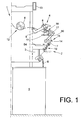
- FIG. 1 One half of a per se known open-end spinning machine is indicated and marked with 1.
- Such spinning machines have a plurality of jobs 2, which are each equipped with a spinning device 3 and a winding device 4.
- the sliver 5 presented in sliver cans 6 is spun into threads 7, which are wound on the winding devices 4 to cheeses 8.
- the winding devices 4 are each equipped with a coil frame 9 for rotatably supporting a cross-wound bobbin 8 or an empty tube and with a single-motor driven winding drum 11 for rotating the cross-wound bobbin 8.
- the open-end spinning machine 1 also has a bobbin transport device 12 for disposing of the cheeses 8 finished on the winding devices 4.
- a (not shown) service unit such as a so-called change and cleaning trolley, be arranged.
- Such service units intervene automatically when a need for action arises at one of the workstations 2.
- Such a need for action exists, for example, if at one of the jobs 2 a full cheese to be replaced with a new empty tube.
- the Fig.2 shows in perspective and on a larger scale one of in Fig.1 schematically indicated job 2 an open-end rotor spinning machine. 1
- Such jobs 2 have, as described above with reference to Fig.1 already explained, inter alia, an open-end spinning device 3 and a winding device.
- a piecing 16 is arranged in the region of the so-called thread withdrawal tube 21 of the open-end spinning device 3, which takes over the 7 after a yarn breakage by the suction nozzle 14 of the cheese 8 and retrieves the thread end prepared for piecing , Furthermore, such jobs 2 have a thread withdrawal device 54, which both the removal of the spun yarn 7 from the open-end spinning device 3 during the takes over regular spinning operation, as well as the re-spinning for a defined return of a prepared thread 7 in the open-end spinning device 3 provides.
- the winding device 4 has a creel 9 for rotatably supporting the cross-wound bobbin 8, a winding drum 11, which can preferably be acted upon by a reversible individual drive 56, and a thread-changing device 18, which is driven, for example, by means of a stepping motor 57.
- self-sufficient workstations 1 each have a pivotably mounted suction nozzle 14, which is adjustable by means of a stepping motor 58 between a thread receiving position lying in the region of the winding device 4 and a yarn transfer position lying in the region of the spinning device 3.
- Each of the jobs 2 also has a thread monitor 26, a paraffining device 17 and a defined under horrbeetztressbare yarn storage nozzle 60, on the one hand during startup of the job 2 and on the other hand in the creation of a final thread reserve 10 is used. That is, by the yarn storage nozzle 60 is stored both during startup of the job 2, as well as during the creation of a final thread reserve 10 excess thread length and thereby ensured that the thread 7 is always wound with a prescribed winding tension.
- both the yarn storage nozzle 60 and the pivotally mounted suction nozzle 14 are connected to a machine-own vacuum network 19, the vacuum source is designated by the reference numeral 30.
- the suction nozzle 14 and the yarn storage nozzle 60 are connected, for example, in each case via a connecting line 22 or 23, to the vacuum network 19 of the textile machine 1.
- connection line 22 In the connecting line 22 is a closure means 24, in connection line 23, a closure means 25 is integrated, wherein the closure means 24 and 25 are connected via control lines 27, 28 to a preferably workstation own control device 29.
- Figure 3 shows a finished cross-wound bobbin 8, that is, a cross-wound bobbin with a final yarn reserve 10, which was created by the method according to the invention.
- some parallel windings 32 preferably three, are disposed on the coil surface 34.
- a thread chord 31 which is easily recognizable by the operating personnel and can be easily handled for detaching the final thread reserve 10.
- the closure means 24 is simultaneously operated via the control device 29 in the sense of "opening" and thus the yarn storage nozzle 60 connected via line 22 to the vacuum network 19 of the textile machine 1.
Abstract
Description
Die Erfindung betrifft ein Verfahren zum Betreiben einer Spulvorrichtung einer Kreuzspulen herstellenden Textilmaschine gemäß dem Oberbegriff des Anspruchs 1 bzw. eine Vorrichtung gemäß Anspruch 5.The invention relates to a method for operating a winding apparatus of a textile machine producing cross-wound bobbins according to the preamble of
Im Zusammenhang mit der Herstellung von Kreuzspulen ist es seit langem üblich, solche Spulkörper sowohl mit einer Fadenanfangsreserve als auch mit einer so genannten Fadenendreserve zu versehen.
Die Fadenendreserve der Kreuzspule wird dabei in der Regel dadurch gebildet, dass nach der Fertigstellung des Spulenkörpers zunächst einige der kreuzweise aufgewickelten Fadenwicklungen wieder vom Spulenkörper abgewickelt und anschließend als Parallelwicklung entweder auf die Spulenoberfläche oder auf die Spitze der Kreuzspulenhülse wieder aufgewickelt werden.In connection with the production of cheeses, it has long been common to provide such bobbins both with a thread initial reserve and with a so-called final yarn reserve.
The Fadenendreserve the cross-wound bobbin is usually formed by the fact that after the completion of the bobbin first some of the cross wound wound thread windings are unwound again from the bobbin and then wound up as a parallel winding either on the bobbin surface or on the top of the cheese package again.
Entsprechende Verfahren und Vorrichtungen zum Erstellen einer solchen Fadenendreserve sind sowohl im Zusammenhang mit Offenend-Spinnmaschinen als auch von Kreuzspulautomaten her in verschiedenen Ausführungsformen bekannt und in zahlreichen Literaturstellen ausführlich beschrieben.Corresponding methods and devices for creating such a final thread reserve are known both in connection with open-end spinning machines and automatic cheese winder in various embodiments and described in detail in numerous references.
Aus der
Beim Wiederaufwickeln wird der von der Kreuzspule zur Saugdüse verlaufende Faden durch Leitmittel an der Saugdüse über die Stirnseite der Kreuzspule hinaus ausgelenkt und dabei in den Bereich eines am Spulenrahmen schwenkbar gelagerten Fadenleitelements befördert.From the
When rewinding, the yarn extending from the cross-wound bobbin to the suction nozzle is deflected by means of guiding means on the suction nozzle beyond the end face of the cross-wound bobbin and thereby conveyed into the area of a yarn guide element pivotally mounted on the creel.
Das durch ein Federelement in der Ruhelage gehaltene Fadenleitelement wird dabei zum Erstellen einer Fadenendreserve durch das Bedienaggregat betätigt.
Das heißt, durch einen am Bedienaggregat angeordneten Schalthebel wird eine Fadenleitkontur des Fadenleitelements in die Nähe des Zwickels, der von dem Garnwickel und der Spulenhülse gebildet wird, gedrückt und sorgt dafür, dass der Faden als Fadenendreserve auf die Spitze der Kreuzspulenhülse aufgewickelt wird.
Der Faden zwischen Hülse und Saugdüse ist dabei aufgrund der in der Saugdüse des Bedienaggregates anliegenden Saugströmung straff gespannt und wird in relativ festen Wicklungen auf die Hülse aufgewickelt.The held by a spring element in the rest position Fadenleitelement is operated to create a final thread reserve by the control unit.
That is, by a shift lever arranged on the operating unit a Fadenleitkontur the Fadenleitelements in the vicinity of the gusset, which is formed by the yarn package and the bobbin, pressed and ensures that the thread is wound up as Fadenendreserve on the top of the cheese package.
The thread between the sleeve and suction nozzle is taut because of the voltage applied to the suction nozzle of the operating unit suction flow and is wound in relatively tight windings on the sleeve.
Ähnliche Verfahren bzw. Vorrichtungen zum Herstellen von Kreuzspulen mit einer Fadenendreserve sind auch in der
Auch bei diesen bekannten Vorrichtungen kommt beim Herstellen der Fadenendreserven der Kreuzspulen stets ein entlang der Arbeitsstellen der Textilmaschine verfahrbares Bedienaggregat zum Einsatz, das von einer Kreuzspule zuerst Faden abwickelt, bevor der Faden erneut in Parallelwicklungen wieder aufgewickelt wird.Similar methods and devices for producing cheeses with a final yarn reserve are also in the
Also in these known devices comes in producing the Fadenendreserven the cheeses always a movable along the workstations of the textile machine operating unit is used, which unwinds first from a cheese first thread before the thread is wound again in parallel windings again.
In der
Zum Erstellen einer Fadenendreserve wird auch bei diesem Spulenwechselwagen zunächst die Saugdüse in den Bereich der Kreuzspulenoberfläche geschwenkt und die Kreuzspule durch den Spulenantrieb in Abwickelrichtung rotiert.
Die Saugdüse nimmt dabei eine gewisse Fadenmenge des auf die Spulenoberfläche aufgelaufene Fadens auf und speichert diese Fadenmenge vorübergehend.In the
To create a final thread reserve, the suction nozzle is first pivoted in the region of the cheeses and also the cross-wound bobbin rotated by the reel drive in the unwinding in this bobbin change car.
The suction nozzle takes on a certain amount of thread accumulated on the bobbin surface thread and stores this amount of thread temporarily.
Anschließend wird die als Spindel ausgebildete Fadenführung in den sich zwischen Kreuzspule und Saugdüse erstreckenden Fadenstrang geschwenkt und die Kreuzspule wieder in Aufwickelrichtung rotiert, wobei Faden aus der Saugdüse herausgezogen wird.
Gemäß einem Ausführungsbeispiel wird der Faden dabei von der Spulenoberfläche heruntergeführt, als Sehne über die Kreuzspulenflanke gezogen und anschließend in Parallelwicklungen auf der Kreuzspulenoberfläche festgelegt.Subsequently, the thread guide designed as a spindle is pivoted into the yarn strand extending between the cheese and the suction nozzle and the cheese is again rotated in the winding direction, with yarn being pulled out of the suction nozzle.
According to one embodiment, the thread is thereby guided down from the coil surface, pulled as a chord over the cheeses flank and then fixed in parallel windings on the cheese surface.
Des Weiteren sind durch die
Diese bekannten Spulstellen weisen eine Fadenchangiereinrichtung mit einem Fadenführer auf, der an einer maschinenlangen Stange angeordnet ist, die, wie die Spulenantriebswalze der Spulstelle, über einen in einem Maschinenendgestell der Textilmaschine angeordneten Gruppenantrieb beaufschlagt wird.
Im Fadenlaufweg vor der Fadenchangiereinrichtung ist eine schwenkbar gelagerte, mit einer Führungskerbe versehene Führungsleiste vorgesehen, die sich über die gesamte Spulenbreite erstreckt.
Diese federkraftbeaufschlagte Führungsleiste ist während des Spulprozesses durch einen ansteuerbaren Riegelmechanismus in ihrer Ruhestellung fixiert und wird, wenn die Kreuzspule einen vorgebbaren Durchmesser erreicht hat, so aufgeschwenkt, dass der Faden aus dem Fadenführer der Fadenchangiereinrichtung gehoben und auf der Führungsleiste in Richtung der im Bereich einer Spulenflanke angeordneten Führungskerbe verlagert wird.
Der in die Führungskerbe gleitende Faden läuft in Parallelwicklungen auf die Kreuzspule auf und bildet dabei, bevor er durch eine zugehörige Fadenschneideinrichtung getrennt wird, eine Fadenendreserve.Furthermore, by the
These known winding units have a Fadenchangiereinrichtung with a thread guide, which is arranged on a machine-length rod, which, like the bobbin drive roller of the winding unit, is acted upon via a arranged in a machine end frame of the textile machine group drive.
In the yarn path in front of the Fadenchangiereinrichtung a pivotally mounted, provided with a guide groove guide bar is provided, which extends over the entire coil width.
This spring-loaded guide rail is fixed during the winding process by a controllable locking mechanism in its rest position and, when the cheese has reached a predetermined diameter, pivoted so that the thread lifted from the thread guide the Fadenchangiereinrichtung and on the guide bar in the direction of the coil flank arranged guide notch is displaced.
The sliding in the guide groove thread runs in parallel windings on the cross-wound bobbin and forms, before it is separated by an associated thread cutting device, a final thread reserve.
Nachteilig bei dieser Einrichtung ist allerdings, dass die Fadenspannung, mit der der Faden beim Erstellen der Parallelwicklungen aufgewickelt wird, gegenüber der Fadenspannung während des "normalen" Spulprozesses erheblich zurückgeht, mit der Folge, dass die Parallelwicklungen relativ locker gewickelt werden.
Bei solchen locker gewickelten Parallelwicklungen besteht dann stets die Gefahr, dass sich die Fadenendreserven während des Transports der Kreuzspulen von den Spulenkörpern lösen.The disadvantage of this device, however, is that the thread tension with which the thread when creating the Parallel windings is wound, compared to the thread tension during the "normal" winding process decreases significantly, with the result that the parallel windings are relatively loosely wound.
In such loosely wound parallel windings then there is always the risk that solve the final yarn reserves during transport of the cheeses from the bobbins.
Durch die gattungsbildende
Der Fadenführer der Fadenchangiereinrichtung ist dabei über eine Steuereinrichtung so ansteuer- und positionierbar, dass eine Fadenendreserve, die aus einer Anzahl Parallelwicklungen besteht, wahlweise auf der Spitze der Kreuzspulenhülse oder auf der Mantelfläche der Kreuzspule angelegt werden kann.
Auch bei solchermaßen ausgebildeten Spulstellen werden die Fadenendreserven sehr locker gewickelt.
Das heißt, auch bei diesen bekannten Einrichtungen besteht die Gefahr, dass sich die relativ locker gewickelten Fadenendreserven, zum Beispiel während des Transportes der Kreuzspulen, unbeabsichtigt vom Spulenkörper bzw. der Spulenhülse lösen.By the
The thread guide of the thread traversing device can be controlled and positioned by a control device in such a way that a final thread reserve, which consists of a number of parallel windings, can optionally be applied to the top of the cross-wound bobbin tube or on the lateral surface of the cross-wound bobbin.
Even with such trained Spulstellen the final thread reserves are wound very loose.
That is, even with these known devices, there is a risk that the relatively loosely wound Fadenendreserven, for example, during transport of the cheeses unintentionally detached from the bobbin or the bobbin.
Ausgehend vom vorstehend beschriebenen Stand der Technik liegt der Erfindung die Aufgabe zugrunde, ein Verfahren bzw. eine Vorrichtung zu entwickeln, das/die die Erstellung einer Kreuzspule mit einer ordnungsgemäßen, sicheren Fadenendreserve bereits im Zuge des Spulprozesses ermöglicht.
Das heißt, ein Verfahren bzw. eine Vorrichtung zu schaffen, bei dem/der bei der Erstellung einer Fadenendreserve auf das Abwickeln und erneute Aufwickeln eines Fadenendes von einer Kreuzspule, insbesondere unter Mithilfe eines Bedienaggregates, verzichtet werden kann.Based on the above-described prior art, the present invention seeks to develop a method and apparatus that allows the creation of a cross-wound bobbin with a proper, secure Fadenendreserve already in the course of the winding process.
That is, to provide a method and a device in which / can be dispensed with in the preparation of a final thread reserve on the unwinding and rewinding a thread end of a cross-wound bobbin, in particular with the help of an operating unit.
Diese Aufgabe wird erfindungsgemäß durch das im Anspruch 1 beschriebene Verfahren beziehungsweise durch die im Anspruch 5 beschriebene Vorrichtung gelöst.This object is achieved by the method described in
Vorteilhafte Ausgestaltungen des erfindungsgemäßen Verfahrens sind Gegenstand der Unteransprüche.Advantageous embodiments of the method according to the invention are the subject of the dependent claims.
Das erfindungsgemäße Verfahren, das vorzugsweise bei Spulstellen zum Einsatz kommt, die einen Spulenrahmen zum frei drehbaren Haltern einer Kreuzspule, eine einzelmotorisch antreibbare Spulenantriebswalze, eine einzelmotorisch antreibbare, definiert ansteuerbare Fadenchangiereinrichtung sowie eine spulstelleneigene Fadenspeichereinrichtung aufweisen, hat den Vorteil, dass die Fadenendreserve bereits zum Ende des "regulären" Spulprozesses durch die Spulstelle selbst durchgeführt werden kann, das heißt, es muss nicht gewartet werden, bis ein Bedienaggregat die Spulstelle anfährt, Faden von der Kreuzspule abwickelt und erneut in Parallelwicklungen wieder aufwickelt.
Durch die Zuschaltung der spulstelleneigenen, unterdruckbeaufschlagbaren Fadenspeicherdüse wird außerdem auf einfache Weise gewährleistet, dass der Faden während des Erstellens dieser Fadenendreserve mit einer ausreichend hohen Fadenspannung gewickelt wird, da während des Wickelns der Fadenreserve der sich aufgrund der Parallelwicklungen einstellende Fadenüberschuss sofort durch die mit Unterdruck beaufschlagte Fadenspeicherdüse als Fadenschlaufe aufgenommen und dadurch der Faden jederzeit straff gehalten wird.The inventive method, which is preferably used in winding stations, which have a creel for freely rotatable holding a cross-wound bobbin, a single motor driven bobbin drive roller, a motor driven, defined controllable Fadenchangiereinrichtung and a winding own filament storage device, has the advantage that the final thread reserve already at the end the "regular" winding process can be performed by the winding unit itself, that is, it does not need to be maintained until an operating unit anfährt the winding unit, unwinding thread from the cross-wound bobbin and rewound again in parallel windings.
By adding the spool its own, unterdruckbeaufschlagbaren yarn storage nozzle is also ensured in a simple manner that the thread is wound during the creation of this final yarn reserve with a sufficiently high yarn tension, as during the winding of the yarn reserve of adjusting itself due to the parallel windings excess yarn immediately acted upon by the negative pressure Filament storage nozzle taken as a thread loop and thereby the thread is kept tight at all times.
Wie in den Ansprüchen 2 und 3 beschrieben, ist in vorteilhafter Ausgestaltung der Erfindung vorgesehen, dass der Faden im Zuge des Erstellens der Fadenendreserve durch den Fadenführer der Fadenchangiereinrichtung zunächst kurz über eine der Spulenflanken der Kreuzspule hinaus und sofort auf die Spulenoberfläche zurückverlegt wird, wo der Faden anschließend in parallelen Wicklungen auf der Spulenoberfläche der Kreuzspule festgelegt wird.As described in
Durch ein solches Verfahren wird einerseits erreicht, dass sich der Faden in Form einer Fadensehne über eine der Spulenflanken erstreckt und damit bei der Weiterverarbeitung der Kreuzspule gut greifbar ist und anderseits wird sichergestellt, dass die Fadenreserve auch während des Transportes der Kreuzspulen ausreichend fest am Spulenkörper fixiert ist.By such a method is on the one hand achieved that the thread extends in the form of a string tendon over one of the coil flanks and thus in the further processing of the cheese well is tangible and on the other hand it is ensured that the thread reserve fixed sufficiently fixed to the bobbin even during transport of the cheeses is.
Als besonders vorteilhaft hat sich erwiesen, wenn der Faden, wie im Anspruch 4 dargelegt, bei einem Kreuzspulendurchmesser von zum Beispiel 350 mm mit drei parallelen Wicklungen auf der Spulenoberfläche der Kreuzspule festgelegt wird.
Durch die Anordnung von vorzugsweise drei Parallelwicklungen ist der Faden sowohl während des Transportes der Kreuzspulen ausreichend sicher an der Spulenoberfläche der Kreuzspule festgelegt, als auch bei Bedarf jederzeit problemlos lösbar.It has proven to be particularly advantageous if the thread, as set forth in
Due to the arrangement of preferably three parallel windings, the yarn is sufficiently securely fixed both to the coil surface of the cross-wound bobbin during the transport of the cross-wound bobbins, and can be easily detached at any time if required.
Die Spulvorrichtung der Kreuzspulen herstellenden Textilmaschine zur Durchführung des erfindungsgemäßen Verfahrens, weist, wie im Anspruch 5 beschrieben, einen Spulenrahmen zum frei drehbaren Haltern einer Kreuzspule, eine über einen Einzelantrieb beaufschlagbare Spulenantriebswalze zum Rotieren der Kreuzspule, eine einzelmotorisch antreibbare, definiert ansteuerbare Fadenchangiereinrichtung sowie eine definiert zuschaltbare Fadenspeicherdüse auf, deren Mündung im Bereich des Laufweges des Fadens angeordnet ist.
Die Fadenspeicherdüse ist ihrerseits an eine Unterquelle angeschlossen und kann bei Bedarf, zum Beispiel durch entsprechende Ansteuerung eines Ventils, mit Unterdruck beaufschlagt werden.
Durch den im Bereich der Mündung der Fadenspeicherdüse anstehenden Unterdruck wird der vorbeilaufende Faden so beaufschlagt, dass überschüssige Fadenlänge, wie sie auf Spulstellen mit konstanter Fadenlieferung bei der Erstellung von Parallelwicklungen unvermeidlich entsteht, sofort als Fadenschlaufe in die Fadenspeicherdüse eingesaugt und damit der Faden straff gehalten wird.The winding device of the cheese-producing textile machine for carrying out the method according to the invention has, as described in claim 5, a creel for freely rotatable holding a cross-wound bobbin, acted upon by a single drive bobbin drive roller for rotating the cheese, a single motor driven, defined controllable Fadenchangiereinrichtung and a defined switchable thread storage nozzle, whose mouth is arranged in the region of the path of the thread.
The yarn storage nozzle is in turn connected to a sub-source and can be acted upon if necessary, for example by appropriate control of a valve, with negative pressure.
By pending in the mouth of the yarn storage nozzle negative pressure of the passing thread is acted upon so that excess thread length, as inevitably arises on winding units with constant yarn delivery in the creation of parallel windings, sucked immediately as a loop of thread in the yarn storage nozzle and thus the thread is kept taut ,
Die Erfindung ist nachfolgend anhand eines in einer Zeichnung dargestellten Ausführungsbeispiel näher erläutert.The invention is explained in more detail with reference to an embodiment shown in a drawing.
Es zeigt:
- Fig.1
- in Seitenansicht eine Hälfte einer Offenend-Spinnmaschine, speziell eine der zahlreichen Arbeitsstellen einer solchen Textilmaschine, die so ausgestattet sind, dass das erfindungsgemäße Verfahren durchgeführt werden kann,
- Fig.2
- die in
Fig.1 dargestellte Arbeitsstelle in perspektivischer Ansicht sowie in einem größeren Maßstab, - Fig.3
- eine Kreuzspule mit einer Fadenendreserve, die nach dem erfindungsgemäßen Verfahren erstellt wurde.
- Fig.1
- in side view one half of an open-end spinning machine, especially one of the numerous jobs of such a textile machine, which are equipped so that the inventive method can be performed
- Fig.2
- in the
Fig.1 illustrated workplace in perspective view and on a larger scale, - Figure 3
- a cross-wound bobbin with a final yarn reserve, which was created by the method according to the invention.
In
Derartige Spinnmaschinen weisen eine Vielzahl von Arbeitsstellen 2 auf, die jeweils mit einer Spinnvorrichtung 3 sowie einer Spuleinrichtung 4 ausgerüstet sind.
In den Spinnvorrichtungen 3 wird das in Spinnkannen 5 vorgelegte Faserband 6 zu Fäden 7 gesponnen, die auf den Spuleinrichtungen 4 zu Kreuzspulen 8 aufgewickelt werden.
Wie angedeutet, sind die Spuleinrichtungen 4 jeweils mit einem Spulenrahmen 9 zum drehbaren Haltern einer Kreuzspule 8 beziehungsweise einer Leerhülse sowie mit einer einzelmotorisch antreibbaren Spultrommel 11 zum Rotieren der Kreuzspule 8 ausgestattet.
Des weiteren verfügen diese beispielsweise in der
Such spinning machines have a plurality of
In the
As indicated, the
Furthermore, these have, for example, in the
Das heißt, die Arbeitsstellen 2 sind so ausgerüstet, dass sie auftretende Fadenbrüche selbsttätig beheben können.
Die Offenend-Spinnmaschine 1 weist außerdem eine Spulentransporteinrichtung 12 zum Entsorgen der auf den Spuleinrichtungen 4 fertig gestellten Kreuzspulen 8 auf.
An beziehungsweise auf der Spinnmaschine 1 kann außerdem an einer Führungsschiene 13 und einer Stützschiene 15 verfahrbar, ein (nicht dargestelltes) Serviceaggregat, beispielsweise ein so genannter Wechsel- und Reinigungswagen, angeordnet sein. Derartige Serviceaggregate greifen selbsttätig ein, wenn an einer der Arbeitsstellen 2 ein Handlungsbedarf entsteht.
Ein solcher Handlungsbedarf liegt beispielsweise vor, wenn an einer der Arbeitsstellen 2 eine volle Kreuzspule gegen eine neue Leerhülse getauscht werden soll.That is, the
The open-
On or on the
Such a need for action exists, for example, if at one of the jobs 2 a full cheese to be replaced with a new empty tube.
Die
Derartige Arbeitsstellen 2 verfügen, wie vorstehend anhand der
Bei diesen an sich bekannten, autarken Arbeitsstellen 2 ist im Bereich des so genannten Fadenabzugsröhrchens 21 der Offenend-Spinnvorrichtung 3 ein Anspinnorgan 16 angeordnet, das den nach einem Fadenbruch durch die Saugdüse 14 von der Kreuzspule 8 zurückgeholten Faden 7 übernimmt und das Fadenende zum Wiederanspinnen vorbereitet.
Des weiteren verfügen solche Arbeitsstellen 2 über eine Fadenabzugseinrichtung 54, die sowohl das Abziehen des Spinnfadens 7 aus der Offenend-Spinnvorrichtung 3 während des regulären Spinnbetriebes übernimmt, als auch beim Wiederanspinnen für eine definierte Rückführung eines vorbereiteten Fadens 7 in die Offenend-Spinnvorrichtung 3 sorgt.The
In these known, self-sufficient jobs 2 a piecing 16 is arranged in the region of the so-called
Furthermore,
Die Spuleinrichtung 4 weist einen Spulenrahmen 9 zum drehbaren Haltern der Kreuzspule 8, eine vorzugsweise über einen reversierbaren Einzelantrieb 56 beaufschlagbare Spultrommel 11 sowie eine Fadenchangiereinrichtung 18 auf, die beispielsweise mittels eines Schrittmotors 57 angetrieben wird.
Des weiteren verfügen derartige autarke Arbeitsstellen 1 jeweils über eine schwenkbar gelagerte Saugdüse 14, die mittels eines Schrittmotors 58 definiert zwischen einer im Bereich der Spulvorrichtung 4 liegenden Fadenaufnahmestellung und einer im Bereich der Spinnvorrichtung 3 liegenden Fadenübergabestellung verstellbar ist.
Jede der Arbeitsstellen 2 weist außerdem einen Fadenwächter 26, eine Paraffiniereinrichtung 17 sowie eine definiert unterdruckbeaufschlagbare Fadenspeicherdüse 60 auf, die einerseits während des Hochlaufens der Arbeitsstelle 2 und anderseits bei der Erstellung eine Fadenendreserve 10 zum Einsatz kommt.
Das heißt, durch die Fadenspeicherdüse 60 wird sowohl während des Hochlaufens der Arbeitsstelle 2, als auch während der Erstellung eine Fadenendreserve 10 überschüssige Fadenlänge gespeichert und dadurch dafür gesorgt, dass der Faden 7 stets mit einer vorschriftsmäßigen Wickelspannung aufgespult wird.The winding
Furthermore, such self-
Each of the
That is, by the
Wie aus
Die Saugdüse 14 und die Fadenspeicherdüse 60 sind, beispielsweise jeweils über eine Anschlussleitung 22 bzw. 23, an das Unterdrucknetz 19 der Textilmaschine 1 angeschlossen.How out
The
In die Anschlussleitung 22 ist dabei ein Verschlussmittel 24, in Anschlussleitung 23 ein Verschlussmittel 25 integriert, wobei die Verschlussmittel 24 bzw. 25 über Steuerleitungen 27, 28 an eine vorzugsweise arbeitsstelleneigene Steuereinrichtung 29 angeschlossen sind.In the connecting
Wie dargestellt, sind auf der Spulenoberfläche 34 einige Parallelwicklungen 32, vorzugsweise drei, angeordnet.
Im Bereich einer der Spulenflanken 35 ist außerdem eine Fadensehne 31 vorhanden, die durch das Bedienpersonal leicht erkennbar ist und zum Ablösen der Fadenendreserve 10 gut handhabbar ist.
As shown, some
In the area of one of the reed flanks 35 there is also a
Während des "normalen" Spinn-/Spulbetriebes wird der in der Spinnvorrichtung 3 hergestellte Faden 7 auf der Spulvorrichtung 4 zu einer Kreuzspule 8 aufgewickelt.
Das heißt, die im Spulenrahmen 9 frei drehbar gehalterte Kreuzspule 8 wird durch die Spulentrommel 11 in Aufwickelrichtung rotiert, während der auflaufende Faden 7 gleichzeitig durch die Fadenchangiereinrichtung 18 traversiert wird.
Wenn die Kreuzspule 8 einen vorgebbaren Durchmesser erreicht hat, was zum Beispiel sensorisch erfasst wird, wird der Fadenführer 40 der Fadenchangiereinrichtung 18 kurz über die reguläre Traversierbreite hinaus verlagert und sofort wieder in den Traversierbereich zurück geführt, wo er in einer vorbestimmten Position gestoppt wird.
Durch diese Fadenführerbewegung wird der Faden 7 kurz über die Spulenflanke 35 hinaus und sofort so wieder zurück auf die Spulenoberfläche 34 verlagert, dass sich eine Fadensehne 31 bildet, die anschließend durch die Parallelwicklungen 32 fixiert wird.During the "normal" spinning / Spulbetriebes the
That is, in the
When the
By this yarn guide movement of the
Bei der Erstellung dieser Fadenendreserve 10 wird gleichzeitig über die Steuereinrichtung 29 das Verschlussmittel 24 im Sinne "Öffnen" betätigt und damit die Fadenspeicherdüse 60 über die Leitung 22 mit dem Unterdrucknetz 19 der Textilmaschine 1 verbunden.
Der dann an der Mündung der Fadenspeicherdüse 60 anstehende Unterdruck beaufschlagt den auf die Kreuzspule 8 auflaufenden Faden 7 dabei so, dass entstehende, überschüssige Fadenlänge sofort als Fadenschlaufe in die Fadenspeicherdüse 60 eingesaugt und dadurch der Faden jederzeit straff gehalten wird.In the preparation of this
The then present at the mouth of the
Claims (5)
dadurch gekennzeichnet,
dass während des Erstellens der Fadenendreserve (10) eine spulstelleneigene, unterdruckbeaufschlagbare Fadenspeicherdüse (60) zugeschaltet wird, die den auf die Kreuzspule (8) auflaufenden Faden (7) so beaufschlagt, dass während des Wickels der Fadenendreserve (10) entstehende, überschüssige Fadenlänge zwischengespeichert und dadurch eine Mindestfadenspannung gewährleistet wird, die notwendig ist, um die Fadenendreserve (10) sicher am Spulenkörper oder der Kreuzspulenhülse zu fixieren.A method for operating a winding device of a cheese-producing textile machine comprising a creel for freely rotatable holding a cross-wound bobbin, a driven via a single drive bobbin drive roller for rotating the cheese and a motor driven, defined controllable Fadenchangiereinrichtung, wherein upon reaching a predetermined cheese diameter or a predetermined yarn length the thread guide of the threading device is positioned either outside the winding area of the cross-wound bobbin or within the winding area of the cross-wound bobbin to create a final thread reserve for an adjustable period of time,
characterized,
in that, during the creation of the final yarn reserve (10), a spooling-own, under-pressurized yarn storage nozzle (60) is switched on, which acts on the yarn (7) running on the cross-wound bobbin (8) so that excess yarn length resulting during the winding of the final yarn reserve (10) is temporarily stored and thereby a minimum thread tension is ensured, which is necessary in order to securely fix the final thread reserve (10) on the bobbin or the cheese package.
dadurch gekennzeichnet,
dass jede der zahlreichen Arbeitsstellen (2) der Offenend-Spinnmaschine (1) mit einer unterdruckbeaufschlagbaren, definiert zuschaltbaren Fadenspeicherdüse (60) ausrüstet ist, deren Mündung im Bereich des Laufweges des auf die Kreuzspule (8) auflaufenden Fadens (7) angeordnet ist.Winding apparatus of a cross-wound textile machine for carrying out the method according to claim 1, comprising a creel for freely rotatable supporting a cross-wound bobbin, a bobbin drive roller for rotating the cross-wound bobbin and a motor driven by a single motor, controllable Fadenchangiereinrichtung,
characterized,
that each of the numerous workstations (2) of the open-end spinning machine (1) is equipped with a vacuum-actuated, selectively switchable yarn storage nozzle (60) whose mouth is arranged in the region of the travel path of the yarn (7) running onto the cross-wound bobbin (8).
Applications Claiming Priority (1)
| Application Number | Priority Date | Filing Date | Title |
|---|---|---|---|
| DE102007023490A DE102007023490A1 (en) | 2007-05-19 | 2007-05-19 | Method and device for operating a winding device of a cross-wound producing textile machine |
Publications (4)
| Publication Number | Publication Date |
|---|---|
| EP1995200A2 true EP1995200A2 (en) | 2008-11-26 |
| EP1995200A3 EP1995200A3 (en) | 2012-04-04 |
| EP1995200B1 EP1995200B1 (en) | 2017-05-31 |
| EP1995200B2 EP1995200B2 (en) | 2020-09-23 |
Family
ID=39712039
Family Applications (1)
| Application Number | Title | Priority Date | Filing Date |
|---|---|---|---|
| EP08007077.4A Active EP1995200B2 (en) | 2007-05-19 | 2008-04-10 | Method and device for operating a winding device of a textile machine which produces crosswound bobbins |
Country Status (4)
| Country | Link |
|---|---|
| US (1) | US20080283655A1 (en) |
| EP (1) | EP1995200B2 (en) |
| CN (1) | CN101306776B (en) |
| DE (1) | DE102007023490A1 (en) |
Cited By (2)
| Publication number | Priority date | Publication date | Assignee | Title |
|---|---|---|---|---|
| CN102139556A (en) * | 2010-11-18 | 2011-08-03 | 江苏舒尔雅家纺有限公司 | Tension-free cloth supplying device of flat screen printing machine production line |
| CN105946339A (en) * | 2016-06-22 | 2016-09-21 | 浙江东山广信数码印花设备有限公司 | Movable cloth sticking device applicable to high-elasticity fabric |
Families Citing this family (7)
| Publication number | Priority date | Publication date | Assignee | Title |
|---|---|---|---|---|
| DE102009009971B4 (en) * | 2009-02-21 | 2017-03-16 | Saurer Germany Gmbh & Co. Kg | Method and apparatus for operating a workstation of a textile machine producing cross-cheeses, and workstation for carrying out the method |
| CN105600588B (en) * | 2016-01-13 | 2017-04-26 | 杭州长翼纺织机械有限公司 | Automatic winding machine |
| CZ309324B6 (en) * | 2016-11-14 | 2022-08-24 | Rieter Cz S.R.O. | A method of defined storage of the end of the yarn on the spool |
| CZ2016708A3 (en) * | 2016-11-14 | 2018-06-06 | Rieter Cz S.R.O. | A method of defined placement of the yarn end on the bobbin |
| CN111547375B (en) * | 2020-05-20 | 2021-12-21 | 台州唯德包装股份有限公司 | PP weaves packing area processing coiling mechanism |
| DE102020127007A1 (en) | 2020-10-14 | 2022-04-14 | Saurer Spinning Solutions Gmbh & Co. Kg | Method of operating a spinning machine and spinning machine |
| DE102021130062A1 (en) | 2021-11-17 | 2023-05-17 | Maschinenfabrik Rieter Ag | Method for operating a winding station of a winding machine and winding machine |
Citations (7)
| Publication number | Priority date | Publication date | Assignee | Title |
|---|---|---|---|---|
| DE1760243A1 (en) | 1968-04-23 | 1971-12-09 | Palitex Project Co Gmbh | Method for winding a cheese and device for carrying out the method |
| DE3602574A1 (en) | 1986-01-29 | 1987-07-30 | Schlafhorst & Co W | CROSS-COIL MANUFACTURING MACHINE WITH MOBILE OPERATING UNIT |
| DE4008001A1 (en) | 1989-03-13 | 1990-09-20 | Murata Machinery Ltd | AUTOMATIC WINDING DEVICE |
| DE4023291A1 (en) | 1990-07-21 | 1992-05-14 | Schubert & Salzer Maschinen | METHOD AND DEVICE FOR FORMING A THREAD FINAL RESERVE DEVELOPMENT ON COILS ON A TEXTILE MACHINE |
| DE4040552C2 (en) | 1989-12-18 | 1993-01-14 | Murata Kikai K.K., Kyoto, Jp | |
| EP1125879A2 (en) | 2000-02-17 | 2001-08-22 | Schärer Schweiter Mettler AG | Device for producing a thread reserve and/or an end ridge of thread |
| DE10139072A1 (en) | 2001-08-09 | 2003-02-20 | Schlafhorst & Co W | Spinning operation restarting service unit for open-end spinning machine positions spinning yarn connected to auxiliary yarn in slot created by tube plate opener, when yarn moving device is moved from resting position |
Family Cites Families (14)
| Publication number | Priority date | Publication date | Assignee | Title |
|---|---|---|---|---|
| US3842579A (en) * | 1972-04-29 | 1974-10-22 | Skf Kugellagerfabriken Gmbh | Apparatus for temporarily storing thread in a spindleless spinning machine |
| JPS5948228B2 (en) * | 1976-04-27 | 1984-11-24 | 株式会社豊田自動織機製作所 | Transfer tail wrapping device |
| DE3734478A1 (en) * | 1987-10-12 | 1989-04-27 | Schubert & Salzer Maschinen | METHOD AND DEVICE FOR GUIDING, HOLDING AND SEPARATING A THREAD WHILE REEL CHANGING |
| DE4004028C2 (en) * | 1990-02-10 | 2001-06-07 | Schlafhorst & Co W | Method and device for forming a thread reserve on a package |
| US5393002A (en) * | 1990-07-21 | 1995-02-28 | Schubert & Salzer Maschinenfabrik Ag | Process and device for the constitution of a yarn end reserve winding on yarn packages of a textile machine |
| DE19650879A1 (en) * | 1996-12-07 | 1998-06-10 | Schlafhorst & Co W | Textile machine producing cross-wound bobbins |
| JP3698873B2 (en) * | 1997-10-03 | 2005-09-21 | ナブテスコ株式会社 | Yarn package forming method and forming apparatus |
| WO1999065810A1 (en) * | 1998-06-12 | 1999-12-23 | Maschinenfabrik Rieter Ag | Yarn changing method |
| EP1161397B1 (en) * | 1999-03-13 | 2003-08-20 | B a r m a g AG | Device and method for guiding and cutting a tapering thread when changing bobbins |
| EP1125880A3 (en) | 2000-02-17 | 2002-08-28 | Schärer Schweiter Mettler AG | Device for producing bobbins in an open-end spinning machine |
| DE10041973A1 (en) * | 2000-08-25 | 2002-03-07 | Rieter Ingolstadt Spinnerei | Open-end spinning device and method for temporarily picking up a thread with the help of such an open-end spinning device |
| DE10139075A1 (en) | 2001-08-09 | 2003-02-20 | Schlafhorst & Co W | Open-end rotor spinning machine |
| DE102005045712A1 (en) | 2005-09-24 | 2007-03-29 | Saurer Gmbh & Co. Kg | Thread take-off roller for a textile machine producing cross-wound bobbins |
| DE102005048041A1 (en) | 2005-10-07 | 2007-04-12 | Saurer Gmbh & Co. Kg | Thread withdrawal device for a cross-wound textile machine |
-
2007
- 2007-05-19 DE DE102007023490A patent/DE102007023490A1/en not_active Withdrawn
-
2008
- 2008-04-10 EP EP08007077.4A patent/EP1995200B2/en active Active
- 2008-05-06 US US12/151,310 patent/US20080283655A1/en not_active Abandoned
- 2008-05-07 CN CN2008100928749A patent/CN101306776B/en active Active
Patent Citations (7)
| Publication number | Priority date | Publication date | Assignee | Title |
|---|---|---|---|---|
| DE1760243A1 (en) | 1968-04-23 | 1971-12-09 | Palitex Project Co Gmbh | Method for winding a cheese and device for carrying out the method |
| DE3602574A1 (en) | 1986-01-29 | 1987-07-30 | Schlafhorst & Co W | CROSS-COIL MANUFACTURING MACHINE WITH MOBILE OPERATING UNIT |
| DE4008001A1 (en) | 1989-03-13 | 1990-09-20 | Murata Machinery Ltd | AUTOMATIC WINDING DEVICE |
| DE4040552C2 (en) | 1989-12-18 | 1993-01-14 | Murata Kikai K.K., Kyoto, Jp | |
| DE4023291A1 (en) | 1990-07-21 | 1992-05-14 | Schubert & Salzer Maschinen | METHOD AND DEVICE FOR FORMING A THREAD FINAL RESERVE DEVELOPMENT ON COILS ON A TEXTILE MACHINE |
| EP1125879A2 (en) | 2000-02-17 | 2001-08-22 | Schärer Schweiter Mettler AG | Device for producing a thread reserve and/or an end ridge of thread |
| DE10139072A1 (en) | 2001-08-09 | 2003-02-20 | Schlafhorst & Co W | Spinning operation restarting service unit for open-end spinning machine positions spinning yarn connected to auxiliary yarn in slot created by tube plate opener, when yarn moving device is moved from resting position |
Cited By (4)
| Publication number | Priority date | Publication date | Assignee | Title |
|---|---|---|---|---|
| CN102139556A (en) * | 2010-11-18 | 2011-08-03 | 江苏舒尔雅家纺有限公司 | Tension-free cloth supplying device of flat screen printing machine production line |
| CN102139556B (en) * | 2010-11-18 | 2012-07-04 | 江苏舒尔雅家纺有限公司 | Tension-free cloth supplying device of flat screen printing machine production line |
| CN105946339A (en) * | 2016-06-22 | 2016-09-21 | 浙江东山广信数码印花设备有限公司 | Movable cloth sticking device applicable to high-elasticity fabric |
| CN105946339B (en) * | 2016-06-22 | 2018-02-13 | 浙江东山广信数码印花设备有限公司 | Suitable for the portable fabric sticking device of High-elasticity fabric |
Also Published As
| Publication number | Publication date |
|---|---|
| EP1995200B1 (en) | 2017-05-31 |
| CN101306776B (en) | 2012-11-14 |
| EP1995200A3 (en) | 2012-04-04 |
| US20080283655A1 (en) | 2008-11-20 |
| CN101306776A (en) | 2008-11-19 |
| DE102007023490A1 (en) | 2008-11-20 |
| EP1995200B2 (en) | 2020-09-23 |
Similar Documents
| Publication | Publication Date | Title |
|---|---|---|
| EP1995200B1 (en) | Method and device for operating a winding device of a textile machine which produces crosswound bobbins | |
| EP2184387B1 (en) | Method for operating an open ended spinning frame and open ended spinning machine | |
| DE102009009971B4 (en) | Method and apparatus for operating a workstation of a textile machine producing cross-cheeses, and workstation for carrying out the method | |
| DE102011101629A1 (en) | Thread splicing device for automatic cheese winder, has smoothening zone extending over length in thread longitudinal direction, where length corresponds to thread ends projecting from channel during splicing process | |
| DE102007053467A1 (en) | Semi-automatic open end-rotor spinning machine operating method, involves utilizing suction nozzle during cross coil/empty case replacement, and automatically connecting pressure source of pressure system of coil if necessary | |
| EP2388222B1 (en) | Method for manufacturing spinning cops | |
| DE102012016853A1 (en) | Method for connecting upper and lower threads at winding station of cross-winding machine, involves pivoting nozzle at thread run after head part is rotated into position, and rotating part into another position after nozzle passes run | |
| EP3421399A1 (en) | Thread-splicing apparatus for pneumatically connecting the ends of yarns | |
| DE10139072A1 (en) | Spinning operation restarting service unit for open-end spinning machine positions spinning yarn connected to auxiliary yarn in slot created by tube plate opener, when yarn moving device is moved from resting position | |
| EP2179954A2 (en) | Textile machine for creating cross-wound spools and method for operating the same | |
| EP1828040B1 (en) | Working spot of a winding frame | |
| DE102016119542A1 (en) | Thread splicing device for a workstation of a cross-wound textile machine | |
| DE102007036696A1 (en) | Rotatable coupling consists of coupling body with ceiling hook and suspension hook for holding light | |
| EP2279976B1 (en) | Method for operating workplaces on a textile machine for creating cross-wound spools | |
| WO2008049486A1 (en) | Method and apparatus for operating a textile machine which produces crosswound bobbins | |
| DE102015010844A1 (en) | Method for connecting an upper and a lower thread at a winding unit of a winding machine and winding unit of a winding machine | |
| EP0979791A2 (en) | Cross wound bobbins producing textile machine | |
| DE102018120457A1 (en) | Thread splicing device for a work station of a textile machine producing cross-wound bobbins | |
| DE102007056563B4 (en) | Tube storage for an open-end rotor spinning machine not equipped with an automatically working piecing unit | |
| DE102004057825A1 (en) | Working spot e.g. for winding frame, has creel for rotatably supporting cross-wound bobbin with device rotating cross-wound bobbin and thread guide for traversing and thread take-off device removing thread from spinning part | |
| DE10007950A1 (en) | Device for starting up a work station of a textile machine producing cross-wound bobbins | |
| DE102008050070A1 (en) | Method for automatic initiation of working position of crossed coil manufactured by textile machine after coiling interruption, particularly after portion change, involves receiving thread coming after grip arm pipe | |
| DE10150590A1 (en) | Bobbin winding station, for automatic cross wound bobbin winding, has a suction jet to catch the yarn end with a moving limit stop to keep it at a constant gap from the bobbin surface | |
| EP2824054B1 (en) | Workstation of a textile machine for creating cross-wound spools | |
| WO2007033784A1 (en) | Service assembly for a textile machine which produces crosswound bobbins |
Legal Events
| Date | Code | Title | Description |
|---|---|---|---|
| PUAI | Public reference made under article 153(3) epc to a published international application that has entered the european phase |
Free format text: ORIGINAL CODE: 0009012 |
|
| AK | Designated contracting states |
Kind code of ref document: A2 Designated state(s): AT BE BG CH CY CZ DE DK EE ES FI FR GB GR HR HU IE IS IT LI LT LU LV MC MT NL NO PL PT RO SE SI SK TR |
|
| AX | Request for extension of the european patent |
Extension state: AL BA MK RS |
|
| PUAL | Search report despatched |
Free format text: ORIGINAL CODE: 0009013 |
|
| AK | Designated contracting states |
Kind code of ref document: A3 Designated state(s): AT BE BG CH CY CZ DE DK EE ES FI FR GB GR HR HU IE IS IT LI LT LU LV MC MT NL NO PL PT RO SE SI SK TR |
|
| AX | Request for extension of the european patent |
Extension state: AL BA MK RS |
|
| RIC1 | Information provided on ipc code assigned before grant |
Ipc: B65H 59/10 20060101ALI20120224BHEP Ipc: B65H 54/34 20060101AFI20120224BHEP Ipc: D01H 1/38 20060101ALI20120224BHEP |
|
| 17P | Request for examination filed |
Effective date: 20121004 |
|
| AKX | Designation fees paid |
Designated state(s): CZ DE IT TR |
|
| RAP1 | Party data changed (applicant data changed or rights of an application transferred) |
Owner name: SAURER GERMANY GMBH & CO. KG |
|
| 17Q | First examination report despatched |
Effective date: 20160121 |
|
| GRAP | Despatch of communication of intention to grant a patent |
Free format text: ORIGINAL CODE: EPIDOSNIGR1 |
|
| INTG | Intention to grant announced |
Effective date: 20161220 |
|
| GRAS | Grant fee paid |
Free format text: ORIGINAL CODE: EPIDOSNIGR3 |
|
| GRAA | (expected) grant |
Free format text: ORIGINAL CODE: 0009210 |
|
| AK | Designated contracting states |
Kind code of ref document: B1 Designated state(s): CZ DE IT TR |
|
| REG | Reference to a national code |
Ref country code: DE Ref legal event code: R096 Ref document number: 502008015337 Country of ref document: DE |
|
| REG | Reference to a national code |
Ref country code: DE Ref legal event code: R026 Ref document number: 502008015337 Country of ref document: DE |
|
| PLBI | Opposition filed |
Free format text: ORIGINAL CODE: 0009260 |
|
| PLAX | Notice of opposition and request to file observation + time limit sent |
Free format text: ORIGINAL CODE: EPIDOSNOBS2 |
|
| 26 | Opposition filed |
Opponent name: MASCHINENFABRIK RIETER AG Effective date: 20180227 |
|
| PLBB | Reply of patent proprietor to notice(s) of opposition received |
Free format text: ORIGINAL CODE: EPIDOSNOBS3 |
|
| REG | Reference to a national code |
Ref country code: DE Ref legal event code: R081 Ref document number: 502008015337 Country of ref document: DE Owner name: SAURER SPINNING SOLUTIONS GMBH & CO. KG, DE Free format text: FORMER OWNER: SAURER GERMANY GMBH & CO. KG, 42897 REMSCHEID, DE |
|
| RAP2 | Party data changed (patent owner data changed or rights of a patent transferred) |
Owner name: SAURER SPINNING SOLUTIONS GMBH & CO. KG |
|
| PGFP | Annual fee paid to national office [announced via postgrant information from national office to epo] |
Ref country code: CZ Payment date: 20190328 Year of fee payment: 12 |
|
| PGFP | Annual fee paid to national office [announced via postgrant information from national office to epo] |
Ref country code: DE Payment date: 20190502 Year of fee payment: 12 |
|
| PLBP | Opposition withdrawn |
Free format text: ORIGINAL CODE: 0009264 |
|
| PUAH | Patent maintained in amended form |
Free format text: ORIGINAL CODE: 0009272 |
|
| STAA | Information on the status of an ep patent application or granted ep patent |
Free format text: STATUS: PATENT MAINTAINED AS AMENDED |
|
| 27A | Patent maintained in amended form |
Effective date: 20200923 |
|
| AK | Designated contracting states |
Kind code of ref document: B2 Designated state(s): CZ DE IT TR |
|
| REG | Reference to a national code |
Ref country code: DE Ref legal event code: R102 Ref document number: 502008015337 Country of ref document: DE |
|
| PG25 | Lapsed in a contracting state [announced via postgrant information from national office to epo] |
Ref country code: CZ Free format text: LAPSE BECAUSE OF NON-PAYMENT OF DUE FEES Effective date: 20200410 |
|
| REG | Reference to a national code |
Ref country code: DE Ref legal event code: R119 Ref document number: 502008015337 Country of ref document: DE |
|
| PG25 | Lapsed in a contracting state [announced via postgrant information from national office to epo] |
Ref country code: DE Free format text: LAPSE BECAUSE OF NON-PAYMENT OF DUE FEES Effective date: 20201103 |
|
| PGFP | Annual fee paid to national office [announced via postgrant information from national office to epo] |
Ref country code: TR Payment date: 20220407 Year of fee payment: 15 |
|
| PGFP | Annual fee paid to national office [announced via postgrant information from national office to epo] |
Ref country code: IT Payment date: 20230428 Year of fee payment: 16 |