EP1991993B2 - Electron beam emitter - Google Patents
Electron beam emitter Download PDFInfo
- Publication number
- EP1991993B2 EP1991993B2 EP07750558.4A EP07750558A EP1991993B2 EP 1991993 B2 EP1991993 B2 EP 1991993B2 EP 07750558 A EP07750558 A EP 07750558A EP 1991993 B2 EP1991993 B2 EP 1991993B2
- Authority
- EP
- European Patent Office
- Prior art keywords
- nozzle
- electron
- bottle
- emitter
- vacuum chamber
- Prior art date
- Legal status (The legal status is an assumption and is not a legal conclusion. Google has not performed a legal analysis and makes no representation as to the accuracy of the status listed.)
- Active
Links
Images


Classifications
-
- G—PHYSICS
- G21—NUCLEAR PHYSICS; NUCLEAR ENGINEERING
- G21K—HANDLING OF PARTICLES OR IONISING RADIATION NOT OTHERWISE PROVIDED FOR; IRRADIATION DEVICES; GAMMA RAY OR X-RAY MICROSCOPES
- G21K5/00—Irradiation devices
- G21K5/04—Irradiation devices with beam-forming means
-
- B—PERFORMING OPERATIONS; TRANSPORTING
- B65—CONVEYING; PACKING; STORING; HANDLING THIN OR FILAMENTARY MATERIAL
- B65B—MACHINES, APPARATUS OR DEVICES FOR, OR METHODS OF, PACKAGING ARTICLES OR MATERIALS; UNPACKING
- B65B55/00—Preserving, protecting or purifying packages or package contents in association with packaging
- B65B55/02—Sterilising, e.g. of complete packages
- B65B55/04—Sterilising wrappers or receptacles prior to, or during, packaging
- B65B55/08—Sterilising wrappers or receptacles prior to, or during, packaging by irradiation
-
- H—ELECTRICITY
- H01—ELECTRIC ELEMENTS
- H01J—ELECTRIC DISCHARGE TUBES OR DISCHARGE LAMPS
- H01J33/00—Discharge tubes with provision for emergence of electrons or ions from the vessel; Lenard tubes
- H01J33/02—Details
-
- A—HUMAN NECESSITIES
- A61—MEDICAL OR VETERINARY SCIENCE; HYGIENE
- A61L—METHODS OR APPARATUS FOR STERILISING MATERIALS OR OBJECTS IN GENERAL; DISINFECTION, STERILISATION OR DEODORISATION OF AIR; CHEMICAL ASPECTS OF BANDAGES, DRESSINGS, ABSORBENT PADS OR SURGICAL ARTICLES; MATERIALS FOR BANDAGES, DRESSINGS, ABSORBENT PADS OR SURGICAL ARTICLES
- A61L2103/00—Materials or objects being the target of disinfection or sterilisation
- A61L2103/23—Containers other than laboratory or medical, e.g. bottles or mail
Definitions
- Electron beam emitters have been used for irradiating and sterilizing containers with electron beams.
- an electron beam emitter is positioned above the container and directs an electron beam downwardly into the container.
- the container is a bottle with a narrow neck
- adequate sterilization of the bottle becomes difficult.
- a narrow neck can block a large portion of the electron beam from entering the bottle.
- DE1010201 discloses irradiating material by rapidly scanning it with a high energy and high intensity electron beam.
- WO0104924 discloses an electron accelerator in a housing with an electron permeable region.
- the nozzle can have a generally circular periphery, and a diameter.
- the vacuum chamber can have a generally circular periphery.
- the electron generator housing can have a diameter that is about the same as the diameter of the nozzle.
- the electron generator can be shaped and dimensioned, and positioned to form the electron beam with a converging portion that converges within the nozzle, followed by diverging portion that diverges within the nozzle before reaching the exit window.
- the electron beam can further diverge after exiting the exit window.
- the electron generating filament can have a portion oriented generally longitudinally in line with the longitudinal axis of the nozzle.
- the nozzle can have a length, and a length to diameter ratio of at least about 3:1.
- the emitter can have a vacuum chamber diameter to nozzle diameter ratio of at least about 2:1.
- the nozzle can have a generally circular periphery, and a diameter.
- the vacuum chamber can have a generally circular periphery.
- the electron generator housing can have a diameter that is about the same as the diameter of the nozzle.
- the electron generator can be shaped and dimensioned, and positioned to form the electron beam with a converging portion that converges within the nozzle, followed by a diverging portion that diverges within the nozzle before reaching the exit window.
- the electron beam can further diverge after exiting the exit window.
- a portion of the filament can be oriented generally longitudinally in line with the longitudinal axis of the nozzle.
- the nozzle can have a length, and a length to diameter ratio of at least about 3:1.
- the vacuum chamber and the nozzle can have a vacuum chamber diameter to nozzle diameter ratio of at least about 2:1.
- the electron generating filament can have a portion oriented generally longitudinally inline with the longitudinal axis of the nozzle.
- the nozzle can have a length, and a length to diameter ratio of at least about 3:1.
- the vacuum chamber and the nozzle can have a vacuum chamber diameter to nozzle diameter ratio of at least about 2:1.
- the distribution of the electron beam within the interior of the bottle can be assisted with at least one electron directing member adjacent to the bottle.
- the interior of the bottle can have an ambient gaseous environment. The gaseous environment can be modified within the bottle.
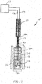
- sterilization system 15 includes an electron beam emitter 10 having a vacuum chamber 11.
- a nozzle 12 ( FIG. 2 ) extends from, and is connected or secured and sealed to the axial end 10a of the vacuum chamber 11.
- An electron beam 44 can be emitted through the nozzle 12.
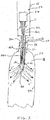
- the nozzle 12 is narrow and elongate, allowing the nozzle 12 to be inserted into the opening 16a of a narrow neck 16 of a container such as a bottle 20, for irradiating the interior 18 of the bottle 20 with the electron beam 44 to irradiate, treat or sterilize surfaces in the interior 18.
- the vacuum chamber 11 can remain outside the bottle 20 while the nozzle 12 is inserted in the neck 16.
- Electrical power to electron beam emitter 10 can be provided by a power source 13 via lines 17a and 17b.
- the interior 18 of the bottle 20 can be irradiated as the nozzle 12 is inserted and/or withdrawn from the bottle 20, or after insertion.
- the distance in which the nozzle 12 is inserted into the bottle 20 can depend upon the size of the bottle 20, including the height, width or diameter, as well as the intensity of the electron beam 44.
- Treatment or sterilization of the interior of the bottle 20 can be achieved by one or more of disabling, killing, destroying, vaporizing, oxidizing, altering, etc., microorganisms and biological substances within the interior 18 and on the interior surfaces 20a of the bottle 20.
- non-biological substances can be treated to neutralize, reduce or remove harmful effects.
- the bottle 20 can be positioned on a support 50 which can move the bottle 20 relative to the nozzle 12. If desired, the support 50 can also be rotated for rotating the bottle 20 to evenly irradiate the interior 18 of the bottle 20.
- One or more electron shaping, spreading or directing plates or members 52 can be provided adjacent to the bottle 20 for distributing, shaping, spreading, directing or assisting electrons e - in the electron beam 44 ( FIG. 3 ) to reach the interior surfaces 20a of the bottle 20 in a desired manner, or pattern or configuration, for treatment or sterilization.
- the electron directing members 52 can assist the distributing, shaping, spreading or directing of the electrons e - with magnetism, or electric potential or charge.
- One or more electron directing members 52 can be located at one or more locations laterally adjacent to the bottle 20, or alternatively, surround the exterior of the bottle 20 laterally circumferentially.
- the support 50 can also be used as a shaping, spreading or directing plate or member, for distributing, shaping, spreading directing, or assisting electrons e - to the bottom interior surface 20b of the bottle 20 in a desired manner, pattern or configuration.
- the support 50 can be provided with magnets, or electric potential or charge.
- the electron directing members 52 and the support 50 can receive power from power source 13.
- a light gas 56 such as helium can be introduced into the bottle 20 by a nozzle or tube 54 to modify the ambient or existing gaseous environment and increase the range of the electron beam 44.
- the gas 56 can be used to form a plasma in conjunction with the electron beam 44, which can assist the treatment or sterilization process.
- nozzle or tube 54 can be a vacuum nozzle or tube for removing air from the bottle 20 to modify the gaseous environment, creating a vacuum or a partial vacuum. This can also increase the range of the electron beam 44 and assist in the treatment or sterilization process.
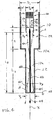
- vacuum chamber 11 of the electron beam emitter 10 can be generally cylindrical and elongate in shape with a width or diameter D 1 ( FIG. 4 ).
- the nozzle 12 can also be generally cylindrical or tubular in shape with a length L 1 , an outer width or diameter D 2 , and an inner width or diameter D 3 .
- the nozzle 12 can be inserted into small openings that would be too small to allow the insertion of an electron beam emitter 10 which did not have a narrow nozzle 12, and instead had an exit window 42 at the axial end 10a of the vacuum chamber 11.
- vacuum chamber 11 with a diameter D 1 that is larger than the diameter D 2 of the nozzle 12 can allow the electron beam emitter 10 to operate at higher power than if the electron beam emitter 10 were constructed to have a single small diameter of the same size as the nozzle 12.
- the vacuum chamber 11 and nozzle 12 are joined together in a manner to have a permanent hermetically sealed vacuum therein.
- An electron gun or generator 24 for generating the electrons e - is positioned within the interior 22 of the vacuum chamber 11, a distance L 2 from the axial proximal end of the nozzle 12, and a distance L 3 from exit window 42 at the axial distal end 14 of nozzle 12.
- the electron generator 24 includes a housing 26 which can be generally cylindrical in shape with a circular periphery, and can have a width or diameter D 4 .
- the housing 26 can include two housing portions 26a and 26b which are joined together ( FIGs. 5 and 6 ). The sides of the housing 26 can be spaced from the interior surfaces 11a of the vacuum chamber 11 by a distance of W which can provide a high voltage gap.
- An electron generating filament 32 is positioned within the interior 34 of the housing 26.
- Power to the electron generating filament 32 can be provided from power source 13 through leads 32a and 32b, which can extend from housing 26 through an insulator 28.
- the electron generating filament 32 can have a portion that is longitudinally positioned in an orientation that is generally in line with the longitudinal axis "X" of the nozzle 12 and vacuum chamber 11 ( FIG. 4 ).
- the electron generating filament 32 can have a slight V-shape ( FIG. 6 ), with leads 32a and 32b extending from a distal end or point 33 at an angle from each other and towards the insulator 28.
- the electron generating filament 32 generates free electrons e - when heated by electrical power passing through the filament 32.
- the general inline orientation of the electron generating filament 32 in electron generator 24 can provide electrons e - in a configuration, arrangement, or location, that is suitable for being focused, or shaped and conveyed or directed through the nozzle 12.
- the V-shape of the electron generating filament 32 can also provide electrons e - in a suitable configuration.
- the electron generating filament 32 extends through an opening 36 in an electrostatic, focusing or shaping lens 30.
- the electrostatic lens 30 provides initial focusing of the electrons e - and can have openings 40 for aiding in providing the desired focus.
- the axial end of the housing 26 has an electron permeable or emitting opening 38 with a diameter D 5 , through which the electrons e - from the filament 32 and electrostatic lens 30 pass, and which forms another electrostatic focusing lens for further focusing the electrons e - emitted from electron generator 24.
- High voltage potential can be provided between housing 26 of the electron generator 24 and the exit window 42 by power source 13.
- the exit window 42 can have a ground 48.
- the voltage potential between the electron generator 24 and the exit window 42 can accelerate the electrons e - emitted by the electron generating filament 32, from the electron generator 24 towards and through the exit window 42.
- the electron generating filament 32 is typically longitudinally positioned, in some embodiments, the electron generating filament 32 can be laterally positioned.
- multiple filaments 32 can be employed.
- the electron generating filament 32 can be a laterally or longitudinally positioned generally circular filament. Examples of some embodiments are depicted in FIGs. 7-11.
- FIGs. 8-11 depict examples where the filament 32 is bent to have a generally circular outer filament portion that substantially surrounds a generally circular inner filament portion.
- the electron generator 24 is positioned within the interior 22 of the vacuum chamber 11 and configured, shaped and dimensioned to form an internal narrow electron beam 46 of a shape and configuration that can travel through the nozzle 12 and emerge out the exit window 42 as electron beam 44.
- the configuration of the electrostatic lens 30, the diameter of the opening 36 in electrostatic lens 30, the distance H at which the electrostatic lens 30 is positioned from the opening 38, the diameter D 5 of the opening 38, and the orientation and configuration of filament 32, can be arranged or configured so that the electrons e - exiting the electron generator 24 exit in a desired configuration.
- the internal electron beam 46 can exit the electron generator 24 in a manner that narrows or converges in a narrowing or converging portion 46a.
- the diameter D 4 of the housing 26 can be generally about the same diameter as the inner diameter D 3 of the nozzle 12, and the diameter D 5 of the opening 38 of the housing 26 can be smaller than the inner diameter D 3 of the nozzle 12. This can allow the converging portion 46a of the internal electron beam 46 to enter the narrow nozzle 12 with little or no blockage.
- the distance L 2 of the electron generator 24 can be also sufficiently spaced from the axial proximal end of the nozzle 12 to allow the converging portion 46a to enter.
- the internal electron beam 46 can converge at a convergence or focus point 46b within the nozzle 12, and then widen, diverge or spread out in a widening, spreading or diverging portion 46c before exiting the exit window 42 in a widening, spreading or diverging external electron beam 44.
- the electron beam 44 can direct electrons e - away from the exit window 42 longitudinally along the longitudial axis "X" as well as circumferentially radially outward relative to axis "X”.
- the electron beam 44 can have an outwardly angled conelike shape.
- the diameter D 4 of the housing 26 and the diameter D 5 of the opening 38 can be larger than the inner diameter D 3 of the nozzle 12.
- the electron generator 24 can be configured and spaced a sufficient distance L 2 to provide an internal electron beam 46 with a converging portion 46a that sufficiently narrows or converges to enter nozzle 12, and a diverging portion 46b that reaches the exit window 42.
- the narrowing or converging, and then widening or diverging configuration of the internal electron beam 46 can keep the internal electron beam 46 narrow while within the nozzle 12 to allow travel of the beam 46 therethrough, and can allow the use of long narrow nozzles 12.
- the length L 1 to inner width or diameter D 3 ratio of the nozzle 12 can be at least about 3:1, for example about 6:1 or greater, and in other embodiments, about 10:1 1 or greater.
- the ratio of the width or diameter D 1 of the vacuum chamber 11 to the outer width or diameter D 2 of the nozzle 12 can be about 2:1, and in other embodiments about 3:1. Depending upon the application at hand, these ratios can vary.
- the beam 46 can be formed in only a diverging manner, but may result in a shorter nozzle for a given inner diameter D 3 , and can be about half as long.
- the nozzle 12 can be tapered.
- the configuration of the electron generator 24, and distances L 2 and L 3 can be adjusted to provide the desired internal electron beam 46 configuration to enter a nozzle 12 of a given length L 1 an inner diameter D 3 , and obtain a desired electron beam 44 configuration exiting the exit window 42.
- the nozzle 12 can have different lengths L 1 , and outer widths or diameters D 2 , for insertion into different sized containers or bottles 20. For example, different sized nozzles 12 can be employed for 12 oz. bottles 20 and 32 oz.
- wider nozzles 12 can be used for wider bottles 20 with wider necks 16, and longer nozzles 12 can be used for taller bottles 12.
- the same nozzle 12 can be used in a range of different sized containers of bottles 20.
- the vacuum chamber 11 and nozzle 12 can be formed of metal, ceramics, or a combination thereof. In one embodiment, the vacuum chamber 11 can have a width or diameter of about 2 inches. Vacuum chamber 11 can have larger or smaller widths and diameters depending upon the application at hand and the desired power levels.
- the housing 26 of the electron generator 24 can be formed of conductive material, for example metal, such as stainless steel. Filament 32 can be formed of a suitable material such as tungsten.
- the electron beam emitter 10 can be operated in a range between about 40 to 150 KV, and about 0 to 5 milliAmps. Alternatively, higher or lower voltages can also be used. It is understood that dimensions and voltage and power levels can vary depending upon the application at hand. Some features of the electron beam emitter 10 can be similar to embodiments disclosed in U.S. Patent Numbers 5,962,995 , 6,407,492 , and 6,545,398 .
- the exit window 42 can extend across substantially the width of the inner diameter D 3 of the nozzle 12 at the axial distal end 14.
- the exit window 42 can be formed of suitable materials, for example, titanium having a thickness of 12.5 microns or less. In some embodiments, the thickness can be between about 4-12 microns thick. Other embodiments can have larger or smaller thicknesses.
- the exit window 42 can have a corrosion resistant covering, for example, gold, diamond, etc.
- the exit window 42 is sealed or bonded to the nozzle 12 to preserve a hermetically sealed vacuum with nozzle 12 and vacuum chamber 11.
- a support plate with holes therethrough can be used to support the exit window 42.
- Other suitable materials and configurations can be employed for exit window 42.
- Exit window 42 can include constructions disclosed in U.S. Application No. 10/751,676, filed January 5, 2004 . In some embodiments, a support plate can be omitted.
- the exit window 42 can be formed of corrosion resistant material without a layer of titanium.
- the vacuum chamber 11 and nozzle 12 have been described to have generally circular peripheries, in other embodiments, the peripheries can be of other suitable shapes, for example, polygonal, such as triangular, rectangular, square, hexagonal, octagonal, etc., or non-circular curves for example, oval, egg shaped, etc.
- the electron beam emitter 10 can be used for irradiating the interior of containers and bottles for purposes other than sterilization, or neutralization for example, for curing, surface treatment, etc.
Landscapes
- Engineering & Computer Science (AREA)
- Physics & Mathematics (AREA)
- General Engineering & Computer Science (AREA)
- High Energy & Nuclear Physics (AREA)
- Health & Medical Sciences (AREA)
- General Health & Medical Sciences (AREA)
- Toxicology (AREA)
- Mechanical Engineering (AREA)
- Apparatus For Disinfection Or Sterilisation (AREA)
Applications Claiming Priority (2)
| Application Number | Priority Date | Filing Date | Title |
|---|---|---|---|
| US77304706P | 2006-02-14 | 2006-02-14 | |
| PCT/US2007/003728 WO2007095205A2 (en) | 2006-02-14 | 2007-02-13 | Electron beam emitter |
Publications (3)
| Publication Number | Publication Date |
|---|---|
| EP1991993A2 EP1991993A2 (en) | 2008-11-19 |
| EP1991993B1 EP1991993B1 (en) | 2013-08-14 |
| EP1991993B2 true EP1991993B2 (en) | 2017-01-25 |
Family
ID=38372076
Family Applications (1)
| Application Number | Title | Priority Date | Filing Date |
|---|---|---|---|
| EP07750558.4A Active EP1991993B2 (en) | 2006-02-14 | 2007-02-13 | Electron beam emitter |
Country Status (6)
| Country | Link |
|---|---|
| US (3) | US7759661B2 (https=) |
| EP (1) | EP1991993B2 (https=) |
| JP (3) | JP5438325B2 (https=) |
| CN (1) | CN101416255B (https=) |
| BR (1) | BRPI0707814B1 (https=) |
| WO (1) | WO2007095205A2 (https=) |
Families Citing this family (77)
| Publication number | Priority date | Publication date | Assignee | Title |
|---|---|---|---|---|
| EP1991993B2 (en) * | 2006-02-14 | 2017-01-25 | Hitachi Zosen Corporation | Electron beam emitter |
| ITMO20070137A1 (it) * | 2007-04-18 | 2008-10-19 | Maria Prudenziati | Sistema innovativo integrato, flessibile e totalmente computerizzato per la produzione e la sterilizzazione di preforme e/o bottiglie in pet di forma e dimensioni diverse, loro sigillatura e marchiatura. |
| EP1982920A1 (de) * | 2007-04-19 | 2008-10-22 | Krones AG | Vorrichtung zum Sterilisieren von Behältnissen |
| DE102008007428B4 (de) * | 2008-02-01 | 2016-02-11 | Khs Gmbh | Verfahren sowie Vorrichtung zum Sterilisieren von Packmitteln |
| DE102008025868A1 (de) | 2008-05-30 | 2009-12-03 | Krones Ag | Vorrichtung zum Sterilisieren von Behältnissen mittels Ladungsträgern |
| DE102008045187A1 (de) * | 2008-08-30 | 2010-03-04 | Krones Ag | Elektronenstrahlsterilisation für Behältnisse |
| SE0802102A2 (sv) | 2008-10-07 | 2010-07-20 | Tetra Laval Holdings & Finance | Styrmetod för en anordning för elektronstrålesterilisering och en anordning för utförande av nämnda metod |
| DE102008054110A1 (de) * | 2008-10-31 | 2010-05-06 | Khs Ag | Vorrichtung zum Sterilisieren eines Behälters |
| EP2218465A1 (de) * | 2009-02-02 | 2010-08-18 | KHS GmbH | Vorrichtung zum Sterilisieren eines Behälters |
| EP2419909B1 (de) * | 2009-04-14 | 2013-01-23 | Siemens AG | Strahlkopf |
| DE102009018210C5 (de) * | 2009-04-21 | 2022-08-18 | Khs Gmbh | Verfahren und Vorrichtung zur Überwachung der Intensität eines Elektronenstrahles |
| US8293173B2 (en) * | 2009-04-30 | 2012-10-23 | Hitachi Zosen Corporation | Electron beam sterilization apparatus |
| US20110012030A1 (en) | 2009-04-30 | 2011-01-20 | Michael Lawrence Bufano | Ebeam sterilization apparatus |
| WO2013170052A1 (en) | 2012-05-09 | 2013-11-14 | Sio2 Medical Products, Inc. | Saccharide protective coating for pharmaceutical package |
| MX350703B (es) | 2009-05-13 | 2017-09-14 | Sio2 Medical Products Inc | Metodo de gasificacion para inspeccionar una superficie revestida. |
| US9458536B2 (en) | 2009-07-02 | 2016-10-04 | Sio2 Medical Products, Inc. | PECVD coating methods for capped syringes, cartridges and other articles |
| DE102009034646A1 (de) * | 2009-07-24 | 2010-09-16 | Siemens Aktiengesellschaft | Strahlkopf |
| FR2953413B1 (fr) | 2009-12-03 | 2011-12-23 | Hema | Systeme de protection pour dispositif de traitement de recipients par faisceau d'electrons |
| DE102009061727B4 (de) * | 2009-12-07 | 2017-09-14 | Crosslinking AB | Elektronenstrahleinheit mit Strahlfeldbegrenzung und Verfahren dazu |
| FR2954704B1 (fr) * | 2009-12-29 | 2012-02-03 | Hema | Systeme de protection en forme de cloche pour dispositif de traitement de recipients par faisceau d'electrons |
| FR2954935B1 (fr) | 2010-01-06 | 2012-04-20 | Hema | Procede et dispositif de traitement de recipients |
| US11624115B2 (en) | 2010-05-12 | 2023-04-11 | Sio2 Medical Products, Inc. | Syringe with PECVD lubrication |
| IT1402423B1 (it) * | 2010-06-11 | 2013-09-04 | Gea Procomac Spa | Dispositivo di formatura di un recipiente ottenuto da una preforma in materiale plastico, metodo di formatura e macchina di formatura |
| JP5737885B2 (ja) * | 2010-08-30 | 2015-06-17 | 三菱重工業株式会社 | 電子線殺菌装置 |
| DE102010044244A1 (de) * | 2010-09-02 | 2012-03-08 | Khs Gmbh | Verfahren sowie Vorrichtung zum Behandeln von Behältern |
| JP5645562B2 (ja) * | 2010-09-10 | 2014-12-24 | 三菱重工業株式会社 | 電子線殺菌装置 |
| US9878101B2 (en) | 2010-11-12 | 2018-01-30 | Sio2 Medical Products, Inc. | Cyclic olefin polymer vessels and vessel coating methods |
| DE102011012342A1 (de) * | 2011-02-24 | 2012-08-30 | Krones Aktiengesellschaft | Verfahren und Vorrichtung zur Sterilisation von Behältnissen |
| FR2972356B1 (fr) * | 2011-03-10 | 2013-03-29 | Serac Group | Procede et installation de sterilisation de recipients par bombardement electronique |
| US9272095B2 (en) | 2011-04-01 | 2016-03-01 | Sio2 Medical Products, Inc. | Vessels, contact surfaces, and coating and inspection apparatus and methods |
| DE102011054097A1 (de) * | 2011-09-30 | 2013-04-04 | Krones Aktiengesellschaft | Vorrichtung und Verfahren zum Sterilisieren von Behältnissen mit in die Behältnisse eingeführter Ladungsträgerquelle |
| JP5738148B2 (ja) | 2011-10-17 | 2015-06-17 | 日立造船株式会社 | 旋回搬送装置を用いた容器の電子線殺菌設備 |
| JP5791459B2 (ja) | 2011-10-17 | 2015-10-07 | 日立造船株式会社 | 電子線殺菌設備の遮蔽構造 |
| US8835873B2 (en) * | 2011-10-26 | 2014-09-16 | Airex Co., Ltd. | Continuous sterilization system |
| US11116695B2 (en) | 2011-11-11 | 2021-09-14 | Sio2 Medical Products, Inc. | Blood sample collection tube |
| EP2776603B1 (en) | 2011-11-11 | 2019-03-06 | SiO2 Medical Products, Inc. | PASSIVATION, pH PROTECTIVE OR LUBRICITY COATING FOR PHARMACEUTICAL PACKAGE, COATING PROCESS AND APPARATUS |
| DE102011055555A1 (de) * | 2011-11-21 | 2013-05-23 | Krones Ag | Vorrichtung zum Sterilisieren eines Behältnisses, Getränkeabfüllanlage und/oder Getränkebehälterherstellanlage sowie Verfahren zum Sterilisieren eines ein von einer Innenwandung umgrenzten Volumen aufweisenden Behältnisses |
| DE102011056162A1 (de) * | 2011-12-08 | 2013-06-13 | Krones Aktiengesellschaft | Vorrichtung und Verfahren zur Sterilisation von Innenwandungen von Behältnissen mit einer Reflektorvorrichtung |
| DE102011056628A1 (de) * | 2011-12-19 | 2013-06-20 | Krones Aktiengesellschaft | Vorrichtung und Verfahren zum Sterilisieren von Behältnissen mit Funktionsüberwachung |
| US20150297800A1 (en) | 2012-07-03 | 2015-10-22 | Sio2 Medical Products, Inc. | SiOx BARRIER FOR PHARMACEUTICAL PACKAGE AND COATING PROCESS |
| CA2890066C (en) | 2012-11-01 | 2021-11-09 | Sio2 Medical Products, Inc. | Coating inspection method |
| US9903782B2 (en) | 2012-11-16 | 2018-02-27 | Sio2 Medical Products, Inc. | Method and apparatus for detecting rapid barrier coating integrity characteristics |
| JP6382830B2 (ja) | 2012-11-30 | 2018-08-29 | エスアイオーツー・メディカル・プロダクツ・インコーポレイテッド | 医療シリンジ、カートリッジ等上でのpecvd堆積の均一性制御 |
| US9764093B2 (en) | 2012-11-30 | 2017-09-19 | Sio2 Medical Products, Inc. | Controlling the uniformity of PECVD deposition |
| DE102012112368A1 (de) * | 2012-12-17 | 2014-06-18 | Krones Ag | Vorrichtung und Verfahren zum Rinsen |
| DE102013101371A1 (de) * | 2013-02-12 | 2014-08-14 | Krones Ag | Vorrichtung zum Sterilisieren von Behältnissen mit Magnetfeldabschirmung |
| US9662450B2 (en) | 2013-03-01 | 2017-05-30 | Sio2 Medical Products, Inc. | Plasma or CVD pre-treatment for lubricated pharmaceutical package, coating process and apparatus |
| US9937099B2 (en) | 2013-03-11 | 2018-04-10 | Sio2 Medical Products, Inc. | Trilayer coated pharmaceutical packaging with low oxygen transmission rate |
| EP2971228B1 (en) | 2013-03-11 | 2023-06-21 | Si02 Medical Products, Inc. | Coated packaging |
| US20160017490A1 (en) | 2013-03-15 | 2016-01-21 | Sio2 Medical Products, Inc. | Coating method |
| EP2991078B1 (en) * | 2013-04-26 | 2018-06-13 | Hitachi Zosen Corporation | Electron beam irradiation apparatus |
| JP6033162B2 (ja) | 2013-05-13 | 2016-11-30 | 日立造船株式会社 | 遮蔽体および電子線容器滅菌設備 |
| JP6076238B2 (ja) * | 2013-11-28 | 2017-02-08 | 日立造船株式会社 | 電子線滅菌装置 |
| JP6543260B2 (ja) | 2014-01-31 | 2019-07-10 | テトラ ラバル ホールディングス アンド ファイナンス エス エイ | 包装容器を殺菌するためのデバイスおよび方法 |
| CN106165282A (zh) * | 2014-02-19 | 2016-11-23 | 利乐拉瓦尔集团及财务有限公司 | 电源单元 |
| WO2015148471A1 (en) | 2014-03-28 | 2015-10-01 | Sio2 Medical Products, Inc. | Antistatic coatings for plastic vessels |
| JP2016154571A (ja) * | 2015-02-23 | 2016-09-01 | 日立造船株式会社 | 内面電子線照射装置 |
| EP3337915B1 (en) | 2015-08-18 | 2021-11-03 | SiO2 Medical Products, Inc. | Pharmaceutical and other packaging with low oxygen transmission rate |
| JP6700782B2 (ja) * | 2015-12-28 | 2020-05-27 | 日立造船株式会社 | 内面電子線照射装置 |
| JP6068693B1 (ja) * | 2016-01-08 | 2017-01-25 | 浜松ホトニクス株式会社 | 電子線照射装置 |
| DE102016006880B3 (de) * | 2016-06-06 | 2017-08-17 | Crosslinking AB | Verfahren zum Bestrahlen eines Behältnisses sowie Elektronenbestrahlungseinheit dazu |
| DE102016008291B3 (de) * | 2016-07-01 | 2017-11-02 | Evonta-Technology Gmbh | Verfahren und Vorrichtung zur Behandlung von Eiern von Geflügel mit Elektronenstrahlen für eine Sterilisation der Kalkschale |
| JP6829576B2 (ja) * | 2016-10-26 | 2021-02-10 | 浜松ホトニクス株式会社 | 電子線照射装置 |
| JP6139771B1 (ja) * | 2016-12-22 | 2017-05-31 | 浜松ホトニクス株式会社 | 電子線照射装置 |
| JP6872380B2 (ja) | 2017-02-03 | 2021-05-19 | 日立造船株式会社 | ノズル式電子線照射装置 |
| CN107014512A (zh) * | 2017-05-31 | 2017-08-04 | 安徽沃兰朵电源技术有限公司 | 一种pet瓶灭菌温度检测系统 |
| JP6843023B2 (ja) * | 2017-09-12 | 2021-03-17 | 日立造船株式会社 | 電子線照射装置およびその製造方法 |
| JP7217157B2 (ja) * | 2019-01-22 | 2023-02-02 | 日立造船株式会社 | 下面電子線滅菌装置 |
| WO2020213109A1 (ja) * | 2019-04-18 | 2020-10-22 | 株式会社日立ハイテク | 電子源、及び荷電粒子線装置 |
| CN111010794A (zh) * | 2019-12-26 | 2020-04-14 | 北京机电工程研究所 | 一种等离子体产生单元及使用方法 |
| US11328390B2 (en) | 2020-05-13 | 2022-05-10 | Ambu A/S | Method for adaptive denoising and sharpening and visualization systems implementing the method |
| CN113903492A (zh) * | 2020-06-22 | 2022-01-07 | 四川智研科技有限公司 | 一种桶形容器内外表面电子束辐照处理方法 |
| CN113903489A (zh) * | 2020-06-22 | 2022-01-07 | 四川智研科技有限公司 | 一种桶形容器内外表面电子束辐照处理装置 |
| CN113903491A (zh) * | 2020-06-22 | 2022-01-07 | 四川智研科技有限公司 | 一种容器内外表面辐照装置 |
| CN113903493A (zh) * | 2020-06-22 | 2022-01-07 | 四川智研科技有限公司 | 一种容器的辐照方法 |
| CN114832124A (zh) * | 2021-02-02 | 2022-08-02 | 湖州超群电子科技有限公司 | 一种开口容器用电子辐照杀菌消毒系统及其使用方法 |
| CN114906420A (zh) * | 2021-02-07 | 2022-08-16 | 湖州超群电子科技有限公司 | 一种用于开口容器的新型电子束杀菌消毒系统及其方法 |
Citations (1)
| Publication number | Priority date | Publication date | Assignee | Title |
|---|---|---|---|---|
| WO2007145561A1 (en) † | 2006-06-13 | 2007-12-21 | Tetra Laval Holdings & Finance S.A. | Method of sterilizing packages |
Family Cites Families (55)
| Publication number | Priority date | Publication date | Assignee | Title |
|---|---|---|---|---|
| US2602751A (en) | 1950-08-17 | 1952-07-08 | High Voltage Engineering Corp | Method for sterilizing substances or materials such as food and drugs |
| NL100100C (https=) * | 1952-02-28 | |||
| US3383163A (en) | 1964-01-24 | 1968-05-14 | Little Inc A | Treatment of surfaces |
| US3621327A (en) | 1969-12-29 | 1971-11-16 | Ford Motor Co | Method of controlling the intensity of an electron beam |
| US3780308A (en) | 1971-06-07 | 1973-12-18 | Energy Sciences Inc | Process and apparatus for surface sterilization of materials |
| GB1454817A (en) * | 1973-09-11 | 1976-11-03 | Sumitomo Electric Industries | Irradiation apparatus |
| US4652763A (en) | 1985-03-29 | 1987-03-24 | Energy Sciences, Inc. | Electron-beam irradiation sterilization process |
| US5011660A (en) | 1987-04-10 | 1991-04-30 | Huls America Inc. | Method of sterilizing medical grade film |
| JP2571437B2 (ja) * | 1989-05-24 | 1997-01-16 | 株式会社豊振科学産業所 | 容器殺菌装置 |
| US4983849A (en) * | 1989-06-05 | 1991-01-08 | Radiation Dynamics, Inc. | Apparatus and method for promoting uniform dosage of ionizing radiation in targets |
| JPH07119837B2 (ja) * | 1990-05-30 | 1995-12-20 | 株式会社日立製作所 | Ct装置及び透過装置並びにx線発生装置 |
| GB2253144B (en) | 1991-03-01 | 1995-07-05 | Atomic Energy Authority Uk | Gas sterilisation |
| SE9301428D0 (sv) | 1993-04-28 | 1993-04-28 | Tetra Laval Holdings & Finance Sa | Elektronaccelerator foer sterilisering av foerpackningsmaterial i en aseptisk foerpackningsmaskin |
| US5422068A (en) | 1994-01-05 | 1995-06-06 | Shalaby; Shalaby W. | Radiochemical sterilization |
| JPH08327799A (ja) * | 1995-05-26 | 1996-12-13 | Iwasaki Electric Co Ltd | 電子線照射装置 |
| SE507282C2 (sv) * | 1995-08-11 | 1998-05-04 | Tetra Laval Holdings & Finance | Sätt att sterilisera fyllfärdiga förpackningar samt användning av en elektronkanon vid sättet |
| JPH09150813A (ja) | 1995-11-30 | 1997-06-10 | Ishikawajima Harima Heavy Ind Co Ltd | 食品容器の殺菌方法及びその殺菌装置 |
| US5730933A (en) | 1996-04-16 | 1998-03-24 | Depuy Orthopaedics, Inc. | Radiation sterilization of biologically active compounds |
| JPH1024092A (ja) * | 1996-07-12 | 1998-01-27 | Yamaura:Kk | 容器内部殺菌装置 |
| US5811943A (en) * | 1996-09-23 | 1998-09-22 | Schonberg Research Corporation | Hollow-beam microwave linear accelerator |
| US5843374A (en) * | 1996-10-11 | 1998-12-01 | Tetra Laval Holdings & Finance, Sa | Method and apparatus for sterilizing packaging |
| US5962995A (en) * | 1997-01-02 | 1999-10-05 | Applied Advanced Technologies, Inc. | Electron beam accelerator |
| DE19882252T1 (de) * | 1997-03-26 | 2000-05-18 | Electron Processing Systems In | Technik zur Innensterilisation eines Behälters mit offener Öffnung mittels Elektronen |
| US6576915B1 (en) * | 1998-02-12 | 2003-06-10 | Mcintyre Peter M. | Method and system for electronic pasteurization |
| JPH11248896A (ja) | 1998-02-27 | 1999-09-17 | Mitsubishi Heavy Ind Ltd | 電子線照射方法及びその装置 |
| JP2949102B1 (ja) * | 1998-04-24 | 1999-09-13 | 株式会社オメガトロン | ビーム発生装置 |
| FR2777810B1 (fr) | 1998-04-28 | 2000-05-19 | Air Liquide | Procede et dispositif de traitement de la surface interne d'une bouteille de gaz |
| CN1369105A (zh) * | 1999-07-09 | 2002-09-11 | 先进电子束公司 | 电子束加速器 |
| US6239543B1 (en) * | 1999-08-23 | 2001-05-29 | American International Technologies, Inc. | Electron beam plasma formation for surface chemistry |
| US6403029B1 (en) * | 2000-01-12 | 2002-06-11 | The Trustees Of Princeton University | System and method of applying energetic ions for sterilization |
| JP2001239131A (ja) * | 2000-02-29 | 2001-09-04 | Mamoru Nakasuji | 脱硫・脱硝装置及びボイラー装置 |
| CN2410874Y (zh) * | 2000-03-31 | 2000-12-20 | 北京清华科技园发展中心 | 粮食的电子束杀虫灭菌装置 |
| JP2002104333A (ja) | 2000-09-25 | 2002-04-10 | Ishikawajima Harima Heavy Ind Co Ltd | 容器の殺菌方法及び装置 |
| JP2002104334A (ja) | 2000-09-28 | 2002-04-10 | Ishikawajima Harima Heavy Ind Co Ltd | 容器の殺菌方法及び装置 |
| FR2815542B1 (fr) | 2000-10-23 | 2004-04-09 | Sidel Sa | Unite de sterilisation et installation de moulage de recipients en matiere plastique munie d'une telle unite |
| BR0116189A (pt) * | 2000-12-04 | 2003-12-16 | Advanced Electron Beams Inc | Aparelho e método para esterização de fluido |
| JP2002243898A (ja) * | 2001-02-13 | 2002-08-28 | Ebara Corp | ビーム取り出し装置 |
| JP2002239342A (ja) * | 2001-02-14 | 2002-08-27 | Ebara Corp | 粒子線照射反応装置 |
| JP2002255124A (ja) | 2001-02-28 | 2002-09-11 | Ishikawajima Harima Heavy Ind Co Ltd | 容器の殺菌方法及び殺菌装置 |
| JP2002255125A (ja) | 2001-02-28 | 2002-09-11 | Ishikawajima Harima Heavy Ind Co Ltd | 容器の殺菌方法及び殺菌装置 |
| US20020182101A1 (en) | 2001-03-27 | 2002-12-05 | Pavel Koulik | Process and device for plasma surface treatment |
| JP4715018B2 (ja) | 2001-04-17 | 2011-07-06 | 株式会社Ihi | 容器の殺菌方法及び殺菌装置 |
| JP2002318299A (ja) * | 2001-04-20 | 2002-10-31 | Ebara Corp | 粒子線取り出し装置及び該装置を用いたボイラ装置 |
| JP2003028999A (ja) * | 2001-07-11 | 2003-01-29 | Ebara Corp | 荷電粒子ビーム制御装置、及びそれを用いた荷電粒子ビーム光学装置、荷電粒子ビーム欠陥検査装置、並びに荷電粒子ビーム制御方法 |
| JP4599023B2 (ja) | 2002-06-21 | 2010-12-15 | 大日本印刷株式会社 | 高電圧パルス電源を用いた包装材料の殺菌方法およびその装置 |
| US7145155B2 (en) * | 2002-08-05 | 2006-12-05 | Electron Porcessing Systems, Inc. | Process for electron sterilization of a container |
| CN1542798A (zh) * | 2003-02-26 | 2004-11-03 | ���µ�����ҵ��ʽ���� | 电子束记录器和电子束照射位置检测方法 |
| JP4307911B2 (ja) | 2003-06-11 | 2009-08-05 | 株式会社ダイゾー | エアゾール容器、エアゾール製品、およびこれらの製造方法 |
| JP4298399B2 (ja) * | 2003-06-26 | 2009-07-15 | キヤノン株式会社 | 電子線装置及び該電子線装置を用いた電子線描画装置 |
| JP2005174568A (ja) * | 2003-12-08 | 2005-06-30 | Ebara Corp | 対物レンズ、電子線装置及びこれらを用いたデバイス製造方法 |
| FR2865135B1 (fr) * | 2004-01-20 | 2007-10-05 | Serac Group | Installation de sterilisation d'articles par bombardement electronique |
| JP4549869B2 (ja) | 2004-02-06 | 2010-09-22 | 三菱重工食品包装機械株式会社 | 殺菌装置及び殺菌方法 |
| GB0416519D0 (en) * | 2004-07-23 | 2004-08-25 | Stenzel Security Ltd | Electronic apparatus |
| US7170068B2 (en) * | 2005-05-12 | 2007-01-30 | Applied Materials, Israel, Ltd. | Method and system for discharging a sample |
| EP1991993B2 (en) * | 2006-02-14 | 2017-01-25 | Hitachi Zosen Corporation | Electron beam emitter |
-
2007
- 2007-02-13 EP EP07750558.4A patent/EP1991993B2/en active Active
- 2007-02-13 BR BRPI0707814-5A patent/BRPI0707814B1/pt active IP Right Grant
- 2007-02-13 US US11/706,075 patent/US7759661B2/en active Active
- 2007-02-13 WO PCT/US2007/003728 patent/WO2007095205A2/en not_active Ceased
- 2007-02-13 CN CN2007800055159A patent/CN101416255B/zh active Active
- 2007-02-13 JP JP2008554420A patent/JP5438325B2/ja active Active
-
2010
- 2010-05-21 US US12/784,983 patent/US8258486B2/en active Active
-
2012
- 2012-07-31 US US13/562,917 patent/US8586944B2/en active Active
-
2013
- 2013-05-02 JP JP2013096812A patent/JP5597743B2/ja active Active
-
2014
- 2014-03-28 JP JP2014067320A patent/JP5774156B2/ja active Active
Patent Citations (1)
| Publication number | Priority date | Publication date | Assignee | Title |
|---|---|---|---|---|
| WO2007145561A1 (en) † | 2006-06-13 | 2007-12-21 | Tetra Laval Holdings & Finance S.A. | Method of sterilizing packages |
Also Published As
| Publication number | Publication date |
|---|---|
| JP2014134548A (ja) | 2014-07-24 |
| US20100247373A1 (en) | 2010-09-30 |
| CN101416255A (zh) | 2009-04-22 |
| US20080073549A1 (en) | 2008-03-27 |
| US20120294758A1 (en) | 2012-11-22 |
| JP2009526971A (ja) | 2009-07-23 |
| BRPI0707814B1 (pt) | 2018-05-02 |
| WO2007095205A3 (en) | 2007-11-29 |
| US8258486B2 (en) | 2012-09-04 |
| EP1991993B1 (en) | 2013-08-14 |
| JP5774156B2 (ja) | 2015-09-02 |
| US7759661B2 (en) | 2010-07-20 |
| JP5597743B2 (ja) | 2014-10-01 |
| JP2013224941A (ja) | 2013-10-31 |
| US8586944B2 (en) | 2013-11-19 |
| JP5438325B2 (ja) | 2014-03-12 |
| EP1991993A2 (en) | 2008-11-19 |
| CN101416255B (zh) | 2012-11-28 |
| WO2007095205A2 (en) | 2007-08-23 |
| BRPI0707814A2 (pt) | 2011-05-10 |
Similar Documents
| Publication | Publication Date | Title |
|---|---|---|
| EP1991993B2 (en) | Electron beam emitter | |
| JP5368426B2 (ja) | Pet容器及びボトルのための殺菌システム | |
| CN101797986B (zh) | 电子射线容器杀菌装置及电子射线容器杀菌方法 | |
| US7148613B2 (en) | Source for energetic electrons | |
| JP2009526971A5 (https=) | ||
| JP5738168B2 (ja) | 電子線殺菌装置 | |
| US20110192986A1 (en) | Electron beam sterilizing device | |
| JP2002308229A (ja) | 容器の殺菌方法及び殺菌装置 | |
| US20100065752A1 (en) | Radially inwardly directed electron beam source and window assembly for electron beam source or other source of electromagnetic radiation | |
| CN103083695A (zh) | 用于通过介质控制电子束为塑料材料容器消毒的装置 | |
| US20050205410A1 (en) | Capillary-in-ring electrode gas discharge generator for producing a weakly ionized gas and method for using the same | |
| EP1699274A1 (en) | Plasma discharger | |
| WO2016114108A1 (en) | Electron beam sterilization system having non-stationary external sterilization emitters moving relative to sterilization objects | |
| JP4386650B2 (ja) | 殺菌装置 | |
| WO2020241758A1 (ja) | 電子線滅菌装置 | |
| JP2017518935A (ja) | パルス電子衝撃による容器のキャップまたは首部の汚染除去方法およびシステム | |
| JP5672696B2 (ja) | 開口容器用電子線照射装置 | |
| WO2023190775A1 (ja) | プラズマナノミスト生成装置 | |
| JPH04341739A (ja) | イオン注入装置のイオン源装置 | |
| JP2002190258A (ja) | イオン発生装置 |
Legal Events
| Date | Code | Title | Description |
|---|---|---|---|
| PUAI | Public reference made under article 153(3) epc to a published international application that has entered the european phase |
Free format text: ORIGINAL CODE: 0009012 |
|
| 17P | Request for examination filed |
Effective date: 20080911 |
|
| AK | Designated contracting states |
Kind code of ref document: A2 Designated state(s): AT BE BG CH CY CZ DE DK EE ES FI FR GB GR HU IE IS IT LI LT LU LV MC NL PL PT RO SE SI SK TR |
|
| 17Q | First examination report despatched |
Effective date: 20110429 |
|
| 111L | Licence recorded |
Designated state(s): AT BE BG CH CY CZ DE DK EE ES FI FR GB GR HU IE IS IT LT LU LV MC NL PL PT RO SE SI SK TR Name of requester: SERAC GROUP, FR Effective date: 20120504 |
|
| RAP1 | Party data changed (applicant data changed or rights of an application transferred) |
Owner name: HITACHI ZOSEN CORPORATION |
|
| DAX | Request for extension of the european patent (deleted) | ||
| RIC1 | Information provided on ipc code assigned before grant |
Ipc: G21K 5/04 20060101AFI20130201BHEP Ipc: B65B 55/08 20060101ALI20130201BHEP Ipc: H01J 33/02 20060101ALN20130201BHEP |
|
| RIC1 | Information provided on ipc code assigned before grant |
Ipc: H01J 33/02 20060101ALN20130225BHEP Ipc: G21K 5/04 20060101AFI20130225BHEP Ipc: B65B 55/08 20060101ALI20130225BHEP |
|
| GRAP | Despatch of communication of intention to grant a patent |
Free format text: ORIGINAL CODE: EPIDOSNIGR1 |
|
| INTG | Intention to grant announced |
Effective date: 20130412 |
|
| GRAS | Grant fee paid |
Free format text: ORIGINAL CODE: EPIDOSNIGR3 |
|
| GRAA | (expected) grant |
Free format text: ORIGINAL CODE: 0009210 |
|
| 111L | Licence recorded |
Designated state(s): AT BE BG CH CY CZ DE DK EE ES FI FR GB GR HU IE IS IT LT LU LV MC NL PL PT RO SE SI SK TR Name of requester: SERAC GROUP, FR Effective date: 20120504 |
|
| AK | Designated contracting states |
Kind code of ref document: B1 Designated state(s): AT BE BG CH CY CZ DE DK EE ES FI FR GB GR HU IE IS IT LI LT LU LV MC NL PL PT RO SE SI SK TR |
|
| REG | Reference to a national code |
Ref country code: GB Ref legal event code: FG4D |
|
| REG | Reference to a national code |
Ref country code: AT Ref legal event code: REF Ref document number: 627251 Country of ref document: AT Kind code of ref document: T Effective date: 20130815 Ref country code: CH Ref legal event code: PK Free format text: ERGAENZUNG LIZENZEINTRAG: NICHT AUSSCHLIESSLICHE LIZENZ Ref country code: CH Ref legal event code: EP |
|
| REG | Reference to a national code |
Ref country code: IE Ref legal event code: FG4D |
|
| REG | Reference to a national code |
Ref country code: CH Ref legal event code: NV Representative=s name: BOVARD AG, CH |
|
| REG | Reference to a national code |
Ref country code: DE Ref legal event code: R096 Ref document number: 602007032248 Country of ref document: DE Effective date: 20131010 |
|
| REG | Reference to a national code |
Ref country code: SE Ref legal event code: TRGR |
|
| REG | Reference to a national code |
Ref country code: NL Ref legal event code: VDEP Effective date: 20130814 Ref country code: AT Ref legal event code: MK05 Ref document number: 627251 Country of ref document: AT Kind code of ref document: T Effective date: 20130814 |
|
| REG | Reference to a national code |
Ref country code: LT Ref legal event code: MG4D |
|
| PG25 | Lapsed in a contracting state [announced via postgrant information from national office to epo] |
Ref country code: IS Free format text: LAPSE BECAUSE OF FAILURE TO SUBMIT A TRANSLATION OF THE DESCRIPTION OR TO PAY THE FEE WITHIN THE PRESCRIBED TIME-LIMIT Effective date: 20131214 Ref country code: LT Free format text: LAPSE BECAUSE OF FAILURE TO SUBMIT A TRANSLATION OF THE DESCRIPTION OR TO PAY THE FEE WITHIN THE PRESCRIBED TIME-LIMIT Effective date: 20130814 Ref country code: AT Free format text: LAPSE BECAUSE OF FAILURE TO SUBMIT A TRANSLATION OF THE DESCRIPTION OR TO PAY THE FEE WITHIN THE PRESCRIBED TIME-LIMIT Effective date: 20130814 Ref country code: CY Free format text: LAPSE BECAUSE OF FAILURE TO SUBMIT A TRANSLATION OF THE DESCRIPTION OR TO PAY THE FEE WITHIN THE PRESCRIBED TIME-LIMIT Effective date: 20130619 Ref country code: PT Free format text: LAPSE BECAUSE OF FAILURE TO SUBMIT A TRANSLATION OF THE DESCRIPTION OR TO PAY THE FEE WITHIN THE PRESCRIBED TIME-LIMIT Effective date: 20131216 |
|
| PG25 | Lapsed in a contracting state [announced via postgrant information from national office to epo] |
Ref country code: SI Free format text: LAPSE BECAUSE OF FAILURE TO SUBMIT A TRANSLATION OF THE DESCRIPTION OR TO PAY THE FEE WITHIN THE PRESCRIBED TIME-LIMIT Effective date: 20130814 Ref country code: PL Free format text: LAPSE BECAUSE OF FAILURE TO SUBMIT A TRANSLATION OF THE DESCRIPTION OR TO PAY THE FEE WITHIN THE PRESCRIBED TIME-LIMIT Effective date: 20130814 Ref country code: LV Free format text: LAPSE BECAUSE OF FAILURE TO SUBMIT A TRANSLATION OF THE DESCRIPTION OR TO PAY THE FEE WITHIN THE PRESCRIBED TIME-LIMIT Effective date: 20130814 Ref country code: GR Free format text: LAPSE BECAUSE OF FAILURE TO SUBMIT A TRANSLATION OF THE DESCRIPTION OR TO PAY THE FEE WITHIN THE PRESCRIBED TIME-LIMIT Effective date: 20131115 Ref country code: BE Free format text: LAPSE BECAUSE OF FAILURE TO SUBMIT A TRANSLATION OF THE DESCRIPTION OR TO PAY THE FEE WITHIN THE PRESCRIBED TIME-LIMIT Effective date: 20130814 Ref country code: FI Free format text: LAPSE BECAUSE OF FAILURE TO SUBMIT A TRANSLATION OF THE DESCRIPTION OR TO PAY THE FEE WITHIN THE PRESCRIBED TIME-LIMIT Effective date: 20130814 |
|
| PG25 | Lapsed in a contracting state [announced via postgrant information from national office to epo] |
Ref country code: CY Free format text: LAPSE BECAUSE OF FAILURE TO SUBMIT A TRANSLATION OF THE DESCRIPTION OR TO PAY THE FEE WITHIN THE PRESCRIBED TIME-LIMIT Effective date: 20130814 |
|
| PG25 | Lapsed in a contracting state [announced via postgrant information from national office to epo] |
Ref country code: NL Free format text: LAPSE BECAUSE OF FAILURE TO SUBMIT A TRANSLATION OF THE DESCRIPTION OR TO PAY THE FEE WITHIN THE PRESCRIBED TIME-LIMIT Effective date: 20130814 Ref country code: CZ Free format text: LAPSE BECAUSE OF FAILURE TO SUBMIT A TRANSLATION OF THE DESCRIPTION OR TO PAY THE FEE WITHIN THE PRESCRIBED TIME-LIMIT Effective date: 20130814 Ref country code: SK Free format text: LAPSE BECAUSE OF FAILURE TO SUBMIT A TRANSLATION OF THE DESCRIPTION OR TO PAY THE FEE WITHIN THE PRESCRIBED TIME-LIMIT Effective date: 20130814 Ref country code: RO Free format text: LAPSE BECAUSE OF FAILURE TO SUBMIT A TRANSLATION OF THE DESCRIPTION OR TO PAY THE FEE WITHIN THE PRESCRIBED TIME-LIMIT Effective date: 20130814 Ref country code: EE Free format text: LAPSE BECAUSE OF FAILURE TO SUBMIT A TRANSLATION OF THE DESCRIPTION OR TO PAY THE FEE WITHIN THE PRESCRIBED TIME-LIMIT Effective date: 20130814 Ref country code: DK Free format text: LAPSE BECAUSE OF FAILURE TO SUBMIT A TRANSLATION OF THE DESCRIPTION OR TO PAY THE FEE WITHIN THE PRESCRIBED TIME-LIMIT Effective date: 20130814 |
|
| PLBI | Opposition filed |
Free format text: ORIGINAL CODE: 0009260 |
|
| PG25 | Lapsed in a contracting state [announced via postgrant information from national office to epo] |
Ref country code: ES Free format text: LAPSE BECAUSE OF FAILURE TO SUBMIT A TRANSLATION OF THE DESCRIPTION OR TO PAY THE FEE WITHIN THE PRESCRIBED TIME-LIMIT Effective date: 20130814 |
|
| PLAX | Notice of opposition and request to file observation + time limit sent |
Free format text: ORIGINAL CODE: EPIDOSNOBS2 |
|
| 26 | Opposition filed |
Opponent name: KRONES AG Effective date: 20140514 Opponent name: FRISCHKNECHT HELLER, STEFFEN Effective date: 20140513 |
|
| REG | Reference to a national code |
Ref country code: DE Ref legal event code: R026 Ref document number: 602007032248 Country of ref document: DE Effective date: 20140513 |
|
| PG25 | Lapsed in a contracting state [announced via postgrant information from national office to epo] |
Ref country code: LU Free format text: LAPSE BECAUSE OF FAILURE TO SUBMIT A TRANSLATION OF THE DESCRIPTION OR TO PAY THE FEE WITHIN THE PRESCRIBED TIME-LIMIT Effective date: 20140213 Ref country code: MC Free format text: LAPSE BECAUSE OF FAILURE TO SUBMIT A TRANSLATION OF THE DESCRIPTION OR TO PAY THE FEE WITHIN THE PRESCRIBED TIME-LIMIT Effective date: 20130814 |
|
| PLBB | Reply of patent proprietor to notice(s) of opposition received |
Free format text: ORIGINAL CODE: EPIDOSNOBS3 |
|
| REG | Reference to a national code |
Ref country code: IE Ref legal event code: MM4A |
|
| PG25 | Lapsed in a contracting state [announced via postgrant information from national office to epo] |
Ref country code: IE Free format text: LAPSE BECAUSE OF NON-PAYMENT OF DUE FEES Effective date: 20140213 |
|
| APBM | Appeal reference recorded |
Free format text: ORIGINAL CODE: EPIDOSNREFNO |
|
| APBP | Date of receipt of notice of appeal recorded |
Free format text: ORIGINAL CODE: EPIDOSNNOA2O |
|
| APAH | Appeal reference modified |
Free format text: ORIGINAL CODE: EPIDOSCREFNO |
|
| REG | Reference to a national code |
Ref country code: FR Ref legal event code: PLFP Year of fee payment: 10 |
|
| APBM | Appeal reference recorded |
Free format text: ORIGINAL CODE: EPIDOSNREFNO |
|
| APBP | Date of receipt of notice of appeal recorded |
Free format text: ORIGINAL CODE: EPIDOSNNOA2O |
|
| APBQ | Date of receipt of statement of grounds of appeal recorded |
Free format text: ORIGINAL CODE: EPIDOSNNOA3O |
|
| APBQ | Date of receipt of statement of grounds of appeal recorded |
Free format text: ORIGINAL CODE: EPIDOSNNOA3O |
|
| PG25 | Lapsed in a contracting state [announced via postgrant information from national office to epo] |
Ref country code: BG Free format text: LAPSE BECAUSE OF FAILURE TO SUBMIT A TRANSLATION OF THE DESCRIPTION OR TO PAY THE FEE WITHIN THE PRESCRIBED TIME-LIMIT Effective date: 20130814 |
|
| PG25 | Lapsed in a contracting state [announced via postgrant information from national office to epo] |
Ref country code: TR Free format text: LAPSE BECAUSE OF FAILURE TO SUBMIT A TRANSLATION OF THE DESCRIPTION OR TO PAY THE FEE WITHIN THE PRESCRIBED TIME-LIMIT Effective date: 20130814 Ref country code: HU Free format text: LAPSE BECAUSE OF FAILURE TO SUBMIT A TRANSLATION OF THE DESCRIPTION OR TO PAY THE FEE WITHIN THE PRESCRIBED TIME-LIMIT; INVALID AB INITIO Effective date: 20070213 |
|
| APBU | Appeal procedure closed |
Free format text: ORIGINAL CODE: EPIDOSNNOA9O |
|
| APAN | Information on closure of appeal procedure modified |
Free format text: ORIGINAL CODE: EPIDOSCNOA9O |
|
| APBU | Appeal procedure closed |
Free format text: ORIGINAL CODE: EPIDOSNNOA9O |
|
| PUAH | Patent maintained in amended form |
Free format text: ORIGINAL CODE: 0009272 |
|
| STAA | Information on the status of an ep patent application or granted ep patent |
Free format text: STATUS: PATENT MAINTAINED AS AMENDED |
|
| 27A | Patent maintained in amended form |
Effective date: 20170125 |
|
| AK | Designated contracting states |
Kind code of ref document: B2 Designated state(s): AT BE BG CH CY CZ DE DK EE ES FI FR GB GR HU IE IS IT LI LT LU LV MC NL PL PT RO SE SI SK TR |
|
| REG | Reference to a national code |
Ref country code: DE Ref legal event code: R102 Ref document number: 602007032248 Country of ref document: DE |
|
| REG | Reference to a national code |
Ref country code: FR Ref legal event code: PLFP Year of fee payment: 11 |
|
| REG | Reference to a national code |
Ref country code: CH Ref legal event code: AELC |
|
| REG | Reference to a national code |
Ref country code: SE Ref legal event code: RPEO |
|
| REG | Reference to a national code |
Ref country code: FR Ref legal event code: PLFP Year of fee payment: 12 |
|
| REG | Reference to a national code |
Ref country code: DE Ref legal event code: R082 Ref document number: 602007032248 Country of ref document: DE Representative=s name: WESTPHAL, MUSSGNUG & PARTNER PATENTANWAELTE MI, DE |
|
| REG | Reference to a national code |
Ref country code: CH Ref legal event code: U11 Free format text: ST27 STATUS EVENT CODE: U-0-0-U10-U11 (AS PROVIDED BY THE NATIONAL OFFICE) Effective date: 20260301 |
|
| PGFP | Annual fee paid to national office [announced via postgrant information from national office to epo] |
Ref country code: SE Payment date: 20260218 Year of fee payment: 20 |
|
| PGFP | Annual fee paid to national office [announced via postgrant information from national office to epo] |
Ref country code: GB Payment date: 20260219 Year of fee payment: 20 |
|
| PGFP | Annual fee paid to national office [announced via postgrant information from national office to epo] |
Ref country code: DE Payment date: 20260218 Year of fee payment: 20 |
|
| PGFP | Annual fee paid to national office [announced via postgrant information from national office to epo] |
Ref country code: IT Payment date: 20260224 Year of fee payment: 20 |
|
| PGFP | Annual fee paid to national office [announced via postgrant information from national office to epo] |
Ref country code: FR Payment date: 20260218 Year of fee payment: 20 |
|
| PGFP | Annual fee paid to national office [announced via postgrant information from national office to epo] |
Ref country code: CH Payment date: 20260301 Year of fee payment: 20 |