EP1991744B1 - Tragsystem aus stahl für dachkonstruktionen - Google Patents
Tragsystem aus stahl für dachkonstruktionen Download PDFInfo
- Publication number
- EP1991744B1 EP1991744B1 EP07702405A EP07702405A EP1991744B1 EP 1991744 B1 EP1991744 B1 EP 1991744B1 EP 07702405 A EP07702405 A EP 07702405A EP 07702405 A EP07702405 A EP 07702405A EP 1991744 B1 EP1991744 B1 EP 1991744B1
- Authority
- EP
- European Patent Office
- Prior art keywords
- booms
- construction according
- support
- diagonals
- support construction
- Prior art date
- Legal status (The legal status is an assumption and is not a legal conclusion. Google has not performed a legal analysis and makes no representation as to the accuracy of the status listed.)
- Active
Links
- 238000010276 construction Methods 0.000 title claims description 36
- 229910000831 Steel Inorganic materials 0.000 title claims description 6
- 239000010959 steel Substances 0.000 title claims description 6
- 238000004519 manufacturing process Methods 0.000 abstract description 6
- 239000011295 pitch Substances 0.000 description 5
- 230000006978 adaptation Effects 0.000 description 4
- 230000003068 static effect Effects 0.000 description 3
- 230000001419 dependent effect Effects 0.000 description 2
- 239000000463 material Substances 0.000 description 2
- 238000009417 prefabrication Methods 0.000 description 2
- 230000000712 assembly Effects 0.000 description 1
- 238000000429 assembly Methods 0.000 description 1
- 238000005452 bending Methods 0.000 description 1
- 239000011230 binding agent Substances 0.000 description 1
- 239000011248 coating agent Substances 0.000 description 1
- 238000000576 coating method Methods 0.000 description 1
- 230000007797 corrosion Effects 0.000 description 1
- 238000005260 corrosion Methods 0.000 description 1
- 230000003247 decreasing effect Effects 0.000 description 1
- 238000011161 development Methods 0.000 description 1
- 230000018109 developmental process Effects 0.000 description 1
- 230000000694 effects Effects 0.000 description 1
Images
Classifications
-
- E—FIXED CONSTRUCTIONS
- E04—BUILDING
- E04C—STRUCTURAL ELEMENTS; BUILDING MATERIALS
- E04C3/00—Structural elongated elements designed for load-supporting
- E04C3/02—Joists; Girders, trusses, or trusslike structures, e.g. prefabricated; Lintels; Transoms; Braces
- E04C3/04—Joists; Girders, trusses, or trusslike structures, e.g. prefabricated; Lintels; Transoms; Braces of metal
- E04C3/08—Joists; Girders, trusses, or trusslike structures, e.g. prefabricated; Lintels; Transoms; Braces of metal with apertured web, e.g. with a web consisting of bar-like components; Honeycomb girders
-
- E—FIXED CONSTRUCTIONS
- E04—BUILDING
- E04B—GENERAL BUILDING CONSTRUCTIONS; WALLS, e.g. PARTITIONS; ROOFS; FLOORS; CEILINGS; INSULATION OR OTHER PROTECTION OF BUILDINGS
- E04B7/00—Roofs; Roof construction with regard to insulation
- E04B7/02—Roofs; Roof construction with regard to insulation with plane sloping surfaces, e.g. saddle roofs
- E04B7/022—Roofs; Roof construction with regard to insulation with plane sloping surfaces, e.g. saddle roofs consisting of a plurality of parallel similar trusses or portal frames
-
- E—FIXED CONSTRUCTIONS
- E04—BUILDING
- E04C—STRUCTURAL ELEMENTS; BUILDING MATERIALS
- E04C3/00—Structural elongated elements designed for load-supporting
- E04C3/02—Joists; Girders, trusses, or trusslike structures, e.g. prefabricated; Lintels; Transoms; Braces
- E04C3/04—Joists; Girders, trusses, or trusslike structures, e.g. prefabricated; Lintels; Transoms; Braces of metal
- E04C2003/0404—Joists; Girders, trusses, or trusslike structures, e.g. prefabricated; Lintels; Transoms; Braces of metal beams, girders, or joists characterised by cross-sectional aspects
- E04C2003/0426—Joists; Girders, trusses, or trusslike structures, e.g. prefabricated; Lintels; Transoms; Braces of metal beams, girders, or joists characterised by cross-sectional aspects characterised by material distribution in cross section
- E04C2003/043—Joists; Girders, trusses, or trusslike structures, e.g. prefabricated; Lintels; Transoms; Braces of metal beams, girders, or joists characterised by cross-sectional aspects characterised by material distribution in cross section the hollow cross-section comprising at least one enclosed cavity
-
- E—FIXED CONSTRUCTIONS
- E04—BUILDING
- E04C—STRUCTURAL ELEMENTS; BUILDING MATERIALS
- E04C3/00—Structural elongated elements designed for load-supporting
- E04C3/02—Joists; Girders, trusses, or trusslike structures, e.g. prefabricated; Lintels; Transoms; Braces
- E04C3/04—Joists; Girders, trusses, or trusslike structures, e.g. prefabricated; Lintels; Transoms; Braces of metal
- E04C2003/0486—Truss like structures composed of separate truss elements
- E04C2003/0491—Truss like structures composed of separate truss elements the truss elements being located in one single surface or in several parallel surfaces
Definitions
- the invention relates to a prefabricated modular structure consisting of hollow sections supporting system made of steel for roof structures according to claim 1.
- prefabricated support systems for roof structures are eg in the US 4,559,748 described.
- Such support systems consist of different interconnected individual support elements, which are exposed according to their load tensile, compressive or bending stresses.
- the invention is therefore based on the object to provide a support system for spans preferably above 20 m, which is flexible to adapt to different spans with low planning and manufacturing costs.
- a support system consisting of prefabricated modular and standardized, made of several different load-bearing interconnected standard modules is used to solve this problem.
- Two standard modules are designed as support elements, made in timber frame construction with straps posts, and diagonals of hollow profiles with constant length.
- Another standard module is designed as a center piece element, consisting of a gridless in length over number and choice of post distances variably adjustable basic module in frame construction with straps and posts made of hollow sections, to set the respective required length each same components are used for different spans.
- This support system is that the center piece is made to adapt to variable spans from a standard base module, which can be adjusted independently of the grid to the achievable spans by using the same components in a simple manner.
- the support elements have independent of the span to be bridged a fixed length.
- the support elements are marked by the grid of the diagonal fields (truss).
- Raster means in this context that z. B. in a base of the isosceles diagonal field of 2 m only a grid of 1 m is possible and thus an overvoltage of z. B. 27.70 m without a change in the diagonal fields is not possible or not feasible.
- the span could be adjusted only by the reduction or expansion of Diagonalfeldern. In In the example described above, this would mean that the span would always have to be increased or decreased by a whole meter.
- the length of the center piece according to the invention can be adjusted without grid.
- the gridless or variable adaptation can be freely selected during the production of the number and choice of the distances of the vertical posts.
- the cross section of the tubes may be circular as well as rectangular or elliptical.
- the standard modules each have the same external dimensions in order to realize a problem-free connection.
- the longitudinal members of the assemblies have the same outer cross-sectional dimensions.
- the flexibility of the support system according to the invention is achieved in that the standardized support elements are designed statically determined and free of nodal deformations.
- the straps and webs remain constant in their dimensions regardless of all spans. Their primary task is to reduce the flow of shear within the structure. The oversizing for large spans remain relatively low.
- the center piece element which allows the gridless variable overvoltage, is statically indeterminate many times, so that the lower part of the thrust flow is reduced by Knotenverfor regulations.
- the higher compressive / tensile stresses of the belts are compensated for unchanged outer diameter by larger wall thicknesses or higher strengths of the material.
- the construction can be utilized better statically at the same time, which can additionally realize material savings by smaller dimensions of the construction and / or the hollow profile cross-sections compared to known support systems.
- the surfaces to be coated are also smaller due to the smaller dimensions of the construction, which has an overall advantageous effect on the coating costs.
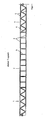
- FIG. 1 shows a according to the invention made of standard modules support system in a flat design.
- the standardized modular structure of the support system consists of three interconnected standard modules.
- Two standard modules are designed as support elements (1), made in truss construction with straps (5) and diagonals (6) of hollow profiles with a constant length.
- Another standard module is designed as a center piece element (2), consisting of a base module in frame construction with straps 3 and post 4 of hollow sections.
- all standard modules have the same external dimensions as the straps 3 of the middle element 2 and the straps 5 of the support element 1 each have the same outer dimensions, so that the standard modules can be easily connected to a support system.
- the wall thickness of the straps 5 of the support elements 1 is smaller than the wall thickness of the straps 3 of the middle element 2.
- the wall thickness of the straps 5 of the support elements 1 is smaller than the wall thickness of the straps 3 of the middle element 2.
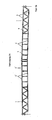
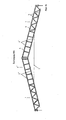
- FIGS. 2a and b show in an alternative embodiment, the support system according to the invention for different roof pitches.
- the same reference numerals correspond to identical components with the same external dimensions. Since the basic concept of the inventive Supporting system can be omitted to avoid repetition on a detailed description.
- the roof pitch is 25%.
- the end portions of the support elements 1 are clamped together in this case via a tension belt 7.
Landscapes
- Engineering & Computer Science (AREA)
- Architecture (AREA)
- Civil Engineering (AREA)
- Structural Engineering (AREA)
- Physics & Mathematics (AREA)
- Electromagnetism (AREA)
- Rod-Shaped Construction Members (AREA)
- Roof Covering Using Slabs Or Stiff Sheets (AREA)
- Conveying And Assembling Of Building Elements In Situ (AREA)
- Tents Or Canopies (AREA)
Abstract
Description
- Die Erfindung betrifft ein vorgefertigtes modular aufgebautes aus Hohlprofilen bestehendes Tragsystem aus Stahl für Dachkonstruktionen gemäß Patentanspruch 1.
DerWo-2006/008176 A offenbart ein Tragsystem aus Stahl für Dachkonstruktionen gemäß dem Oberbegriff des Anspruchs 1. - Aus Hohlprofilen bestehende vorgefertigte Tragsysteme für Dachkonstruktionen werden z.B. in der
US 4,559,748 beschrieben. - Derartige Tragsysteme bestehen aus verschiedenen miteinander verbundenen einzelnen Tragelementen, die entsprechend ihrer Belastung Zug-, Druck- oder Biegebeanspruchungen ausgesetzt sind.
- Für die Tragelemente werden entsprechend ihrer planmäßigen Beanspruchung ausgelegte Fachwerkkonstruktionen, bestehend aus Gurten und Diagonalen, verwendet, die anschließend zu einem Tragsystem miteinander verbunden werden.
- Derartige Tragsysteme haben den Nachteil, dass für jedes Dachsystem bzw. für unter schiedliche Spannweiten rasterabhängig eine Einzelplahung bzw. Einzelstatik notwendig ist, mit den daraus resultierenden hohen Kosten und entsprechend längeren Lieferzeiten.
- Gerade für große Spannweiten, z. B. oberhalb von 20 m, sind bekannte Tragsysteme auf grund der individuellen Planung und Fertigung sehr unwirtschaftlich, da die konstruktive Auslegung sehr aufwändig wird. Eine kostengünstige und zeitnahe Belieferung des Kunden ist mit diesen bekannten vorgefertigten Tragsystemen aus Stahl-Hohlprofilen nicht möglich.
- Der Erfindung liegt daher die Aufgabe zugrunde, ein Tragsystem für Spannweiten vorzugsweise oberhalb von 20 m anzugeben, die mit geringem Planungs- und Fertigungsaufwand flexibel an unterschiedliche Spannweiten anzupassen ist.
- Diese Aufgabe wird mit den Merkmalen des Anspruches 1 gelöst. Vorteilhafte Weiterbildungen sind jeweils Gegenstand von Unteransprüchen.
- Nach der Lehre der Erfindung wird zur Lösung dieser Aufgabe ein Tragsystem, bestehend aus vorgefertigten modular und standardisiert aufgebauten, aus mehreren unterschiedlich belastbaren miteinander verbundenen Standardmodulen, verwendet.
- Zwei Standardmodule sind als Auflagerelemente ausgebildet, hergestellt in Fachwerkbauweise mit Gurten Pfosten, und Diagonalen aus Hohlprofilen mit konstanter Länge. Ein weiteres Standardmodul ist als Mittelstückelement ausgebildet, bestehend aus einem rasterlosen in der Länge über Anzahl und Wahl der Pfostenabstände variabel anpassbaren Grundmodul in Rahmenbauweise mit Gurten und Pfosten aus Hohlprofilen, wobei zur Einstellung der jeweils geforderten Länge jeweils gleiche Bauteile für unterschiedliche Spannweiten verwendet werden.
- Der Vorteil dieses Tragsystems besteht darin, dass das Mittelstück zur Anpassung an variable Spannweiten aus einem Standard-Grundmodul hergestellt ist, welches rasterunabhängig an die zu erreichenden Spannweiten durch Verwendung gleicher Bauteile auf einfache Weise angepasst werden kann.
- Erreicht wird dies zum Einen durch die Standardisierung der Auflagerelemente mit konstanter Länge und durch den modularen Aufbau des Mittelstückes, wodurch eine flexible und kostengünstige Anpassung des Mittelstück-Grundmoduls an unterschiedliche Spannweiten der Dachkonstruktion ermöglicht wird.
- Bei dem erfindungsgemäßen Tragsystem für Dachkonstruktionen besitzen die Auflager elemente unabhängig von der zu überbrückenden Spannweite eine fixe Länge. Die Auflagerelemente sind durch die Raster der Diagonalfelder.(Fachwerk) gekennzeichnet.
- Raster bedeutet in diesem Zusammenhang, dass z. B. bei einer Basis des gleichschenkligen Diagonalfeldes von 2 m nur ein Raster von 1 m möglich ist und somit eine Überspannung von z. B. 27,70 m ohne eine Veränderung der Diagonalfelder nicht möglich bzw. nicht ausführbar ist.
- Ohne das erfindungsgemäße Mittelstückelement in Rahmenbauweise könnte die Spannweite nur durch die Verringerung oder Erweiterung von Diagonalfeldern angeglichen werden. In dem oben beschriebenen Beispiel würde das bedeuten, dass die Spannweite immer um einen ganzen Meter erhöht bzw. verringert werden müsste.
- Eine Änderung der Diagonalfelder - bzw. der Länge der Basis - welche unabdingbar wäre, um jede beliebige Spannweite darzustellen, ließe keine Vorfertigung und damit auch keine standardisierte Bemessung zu.
- Hier setzt aber genau die Erfindung an. Für die Anpassung der Binderlänge an die Spannweite der Dachkonstruktion kann die Länge des Mittelstückes erfindungsgemäß rasterlos angepasst werden. Die rasterlose bzw. variable Anpassung kann dabei über Anzahl und Wahl der Abstände der senkrechten Pfosten während der Fertigung frei gewählt werden.
- Diese rasterlose und damit variable Einstellung der erforderlichen Länge des Mittelstückelementes ist jedoch nur durch die beschriebene Rahmenbauweise realisierbar.
- Da für unterschiedliche Spannweiten nicht wie bei Fachwerkträgem die Grundkonstruktion geändert werden muss, sondern nur die Länge des Mittelstückelementes den jeweiligen Erfordernissen angepasst wird, ist für derartige Tragsysteme vorteilhafterweise nur eine Typenstatik erforderlich.
- Als Hohlprofile für die Gurte und Diagonalen bzw. Pfosten der Standardmodule der Tragsysteme kommen sowohl warmgefertigte nahtlose Rohre als auch geschweißte kalt- oder warmgefertigte gefertigte Rohre in Betracht. Der Querschnitt der Rohre kann dabei je nach Beanspruchung sowohl kreisförmig wie auch rechteckig oder elliptisch ausgebildet sein.
- Vorteilhaft weisen die Standardmodule jeweils gleiche Außenabmessungen auf, um eine problemlose Verbindung realisieren zu können. Idealerweise besitzen dazu insbesondere auch die Längsträger der Baugruppen gleiche äußere Querschnittsabmessungen.
- Erreicht wird die Flexibilität des erfindungsgemäßen Tragsystems dadurch, dass die standardisierten Auflagerelemente statisch bestimmt konzipiert und frei von Knotenverformungen sind. Die Gurte und Stege bleiben unabhängig von allen Spannweiten in ihren Dimensionen konstant. Sie haben vornehmlich die Aufgabe den Schubfluss innerhalb der Konstruktion abzubauen. Die Überdimensionierungen bei großen Spannweiten bleiben im Verhältnis gering.
- Das Mittelstückelement, welches die rasterlose variable Überspannung ermöglicht, ist mehrfach statisch unbestimmt, so dass der geringere Teil des Schubflusses durch Knotenverfor mungen abgebaut wird. Die höheren Druck-/Zugbeanspruchungen der Gurte werden bei unverändertem Außendurchmesser durch größere Wanddicken bzw. höhere Festigkeiten des Materials ausgeglichen.
- Im Firstbereich werden für verschiedene zu realisierende Dachneigungen Drehknoten eingesetzt, wobei der Neigungswinkel über Adaption des Knotens im Untergurt eingestellt wird. Bei auflagerempfindlichen Systemen werden die mittelstückseitigen Endknoten der Auflager elemente miteinander verspannt. Das Dach kann dabei beliebig geneigt sein.
- In vorteilhafter Weise ist für das aus Standardmodulen aufgebaute Tragsystem nur noch eine Typenstatik notwendig, wodurch sich die Kosten für den Planungs- und Fertigungsaufwand emorm verringern.
- Durch die Vorfertigung in modularer Bauweise, bei der gleiche Bauteile für unterschiedliche Spannweiten verwendet werden, verringern sich zudem vorteilhaft die Fertigungs- und damit die Lieferzeiten für den Kunden, und es kann wesentlich flexibler auf kurzfristig geänderte Kundenwünsche reagiert werden.
- Durch die beschriebene Ausnutzung der Knotenverformungen im Mittelstück, kann die Konstruktion gleichzeitig statisch besser ausgenutzt werden, wodurch sich im Vergleich zu bekannten Tragsystemen zusätzlich Materialeinsparungen durch kleinere Dimensionierung der Konstruktion und/oder der Hohlprofil-Querschnitte realisieren lassen.
- Bei Konstruktionen, die aus ästhetischen oder Korrosionsgründen beschichtet werden müssen, sind die zu beschichtenden Flächen durch die kleinere Dimensionierung der Konstruktion ebenfalls kleiner, was sich insgesamt vorteilhaft auf die Beschichtungskosten auswirkt.
- Nachfolgend wird die Erfindung anhand zweier Figuren näher erläutert. Gleiche Bezugszeichen in unterschiedlichen Figuren bezeichnen gleiche Bauteile mit gleichen Außenabmessungen. Es zeigen:
-
Figur 1 ein erfindungsgemäß aus Standardmodulen hergestelltes ebenes Tragsystem, -
Figur 2a wieFigur 1 , jedoch mit einer Dachneigung von 2%, -
Figur 2b wieFigur 1 , jedoch mit einer Dachneigung von 25%. -
Figur 1 zeigt ein erfindungsgemäß aus Standardmodulen hergestelltes Tragsystem in ebener Ausführung. - Der standardisierte modulare Aufbau des Tragsystems besteht aus drei miteinander ver bundenen Standardmodulen. Zwei Standardmodule sind als Auflagerelemente (1) ausgebildet, hergestellt in Fachwerkbauweise mit Gurten (5) und Diagonalen (6) aus Hohlprofilen mit konstanter Länge. Ein weiteres Standardmodul ist als Mittelstückelement (2) ausgebildet, bestehend aus einem Grundmodul in Rahmenbauweise mit Gurten 3 und Pfosten 4 aus Hohlprofilen.
- Unterschiedliche Spannweiten sind in einfacher Weise dadurch zu erreichen, dass das modular aufgebaute Mittelstückelement 2 variabel über Anzahl und Wahl der senkrechten Pfostenabstände der benötigten Länge angepasst wird, wobei jeweils die gleichen Bauteile für unterschiedliche Spannweiten verwendet werden.
- Vorteilhaft besitzen alle Standardmodule gleiche Außenabmessungen wie auch die Gurte 3 des Mittelstückelementes 2 und die Gurte 5 des Auflagerelementes 1 jeweils gleiche Außenabmessungen besitzen, so dass sich die Standardmodule leicht zu einem Tragsystem verbinden lassen.
- Angepasst an die unterschiedliche Belastung ist die Wanddicke der Gurte 5 der Auflagerelemente 1 kleiner dimensioniert als die Wanddicke der Gurte 3 des Mittelstückelementes 2. Je nach Belastung unterschiedlich oder gleich dimensioniert sind in Querschnitt und Wanddicke auch die Diagonalen 6 des Auflagerelementes 1 und die Pfosten 4 des Mittelsülck-elementes 2.
- Alternativ kann jedoch auch eine Anpassung an unterschiedliche Belastungen über die Auswahl einer geeigneten Stahlsorte mit entsprechenden mechanischen Kennwerten vorgenommen werden.
- Die
Figuren 2a und b zeigen in einer alternativen Ausgestaltung das erfindungsgemäße Tragsystem für unterschiedliche Dachneigungen. Gleiche Bezugszeichen entsprechen gleichen Bauteilen mit gleichen Außenabmessungen. Da das Grundkonzept dem des erfindungsgemäßen Tragsystems entspricht, kann zur Vermeidung von Wiederholungen auf eine detaillierte Beschreibung verzichtet werden. - Anders als bei dem Tragsystem nach
Figur 1 ist das Mittelstückelement 2' inFigur 2a jedoch nicht als ebene Konstruktion ausgeführt, sondern ist im Mittenbereich geknickt, wobei sich in diesem Fall eine Dachneigung von 2% ergibt. - Bei dem in
Figur 2b dargestellten Tragsystem beträgt die Dachneigung 25%. Die Endbereiche der Auflagerelemente 1 sind in diesem Fall über einen Zuggurt 7 miteinander verspannt. -
Nr. Bezeichnung 1 Auflagerelement 2, 2', 2" Mittelstückelement 3, 3', 3" Gurte Mittelstückelement 4 Pfosten Mittelstückelement 5 Gurte Auflagerelement 6 Diagonalen Auflagerelement 7 Zuggurt
Claims (15)
- Tragsystem aus Stahl für Dachkonstruktionen mit Spannweiten, vorzugsweise länger als 20 m, bestehend aus vorgefertigten modular und standardisiert aufgebauten, aus mehreren unterschiedlich belastbaren miteinander verbundenen Standardmodulen, wobei zwei Standardmodule als Auflagerelemente (1) ausgebildet sind, und ein Standardmodul als Mittelstückelement (2, 2', 2") ausgebildet ist dadurch gekemzeichnet, dass die zwei Auflagerelemente (1) in Fachwerkbauweise mit Gurten (5), Pfosten (4) und Diagonalen (6) aus Hohlprofilen mit konstanter Länge,
rasterlosen, hergestellt sind, und dass des Mittelstückelement (2,2'2") aus einem in rasterlosen der Länge über Anzahl und Wahl der Pfostenabstände variabel anpassbaren Grundmodul in Rahmenbauweise mit Gurten (3, 3', 3") und Pfosten (4) aus Hohlprofilen besteht, wobei zum Erreichen der geforderten länger des Mittelstückelementes (2, 2', 2") jeweils gleiche Bauteile für unterschiedliche Spannweiten verwendet werden. - Tragkonstruktion nach Anspruch 1
dadurch gekennzeichnet,
dass die Gurte (3, 3', 3", 5), Pfosten (4) und Diagonalen (6) aus warmgefertigten, nahtlosen Rohren hergestellt sind. - Tragkonsiruktion nach Anspruch 1
dadurch gekennzeichnet,
dass die Gurte (3, 3', 3", 5), Pfosten (4) und Diagonalen (6) aus geschweißten, kalt-
oder warmgefertigten Rohren hergestellt sind. - Tragkonstruktion nach einem der Ansprüche 1 - 3
dadurch gekennzeichnet,
dass die Gurte (5), Pfosten (4) und Diagonalen (6) des in Fachwerkbauweise hergestellten Auflagerelementes (1) unterschiedliche Querschnittsabmessungen aufweisen. - Tragkonstruktion nach Anspruch 4
dadurch gekennzeichnet,
dass die Gurte (5), Pfosten (4) und Diagonalen (6)-unterschiedliche Wanddicken aufweisen. - Tragkonstruktion nach einem der Ansprüche 1 - 5
dadurch gekennzeichnet,
dass die Gurte (3, 3', 3"), des in Rahmenbauweise hergestellten Mittelstückelementes (2, 2', 2") unterschiedliche Querschnittsabmessungen aufweisen. - Tragkonstruktion nach Anspruch 6
dadurch gekennzeichnet,
dass die Gurte (3, 3', 3"), Pfosten (4) und Diagonalen (6) unterschiedliche Wanddicken aufweisen. , - Tragkonstruktion nach einem der Ansprüche 1 - 7
dadurch gekennzeichnet,
dass die Gurte (5) der Auflagerelemente (1) und die-Gurte (3, 3', 3") des Mittelstückelementes (2, 2', 2") gleiche Querschnittsabmessungen aufweisen. - Tragkonstruktion nach einem der Ansprüche 1 - 8
dadurch gekennzeichnet,
dass die Auflagerelemente (1) und das Mittelstückelement (2, 2', 2") gleich Außenabmessungen aufweisen. - Tragkonstruktion nach einem der Ansprüche 1 - 9
dadurch gekennzeichnet,
dass die Gurte (3, 3', 3", 5), Pfosten (4) und Diagonalen (6) einen kreisförmigen Querschnitt aufweisen. - Tragkonstruktion nach einem der Ansprüche 1 - 9
dadurch gekennzeichnet,
dass die Gurte (3, 3', 3", 5) Pfosten (4) und Diagonalen (6),einen rechteckigen Querschnitt aufweisen. - Tragkonstruktion nach einem der Ansprüche 1 - 9
dadurch gekennzeichnet,
dass die Gurte (3, 3', 3", 5), Pfosten (4) und Diagonalen (6) einen elliptischen Querschnitt aufweisen. - Tragkonstruktion nach einem der Ansprüche 1 -12
dadurch gekennzeichnet,
dass das Mittelstückelement (2) eben ausgebildet ist. - Tragkonstruktion nach einem der Ansprüche 1 -12
dadurch gekennzeichnet,
dass das Mittelstückelement (2', 2") eine Dachneigung bildende Knickung aufweist. - Tragkonstruktion nach Anspruch 13
dadurch gekennzeichnet,
dass die Dachneigung einen Wert von z.B. 0 bis 35 % annimmt.
Priority Applications (1)
| Application Number | Priority Date | Filing Date | Title |
|---|---|---|---|
| PL07702405T PL1991744T3 (pl) | 2006-03-03 | 2007-01-26 | Układ nośny ze stali dla konstrukcji dachowych |
Applications Claiming Priority (2)
| Application Number | Priority Date | Filing Date | Title |
|---|---|---|---|
| DE102006010951A DE102006010951A1 (de) | 2006-03-03 | 2006-03-03 | Tragsystem aus Stahl für Dachkonstruktionen |
| PCT/DE2007/000174 WO2007098727A1 (de) | 2006-03-03 | 2007-01-26 | Tragsystem aus stahl für dachkonstruktionen |
Publications (2)
| Publication Number | Publication Date |
|---|---|
| EP1991744A1 EP1991744A1 (de) | 2008-11-19 |
| EP1991744B1 true EP1991744B1 (de) | 2011-04-20 |
Family
ID=38109603
Family Applications (1)
| Application Number | Title | Priority Date | Filing Date |
|---|---|---|---|
| EP07702405A Active EP1991744B1 (de) | 2006-03-03 | 2007-01-26 | Tragsystem aus stahl für dachkonstruktionen |
Country Status (13)
| Country | Link |
|---|---|
| EP (1) | EP1991744B1 (de) |
| AR (1) | AR059694A1 (de) |
| AT (1) | ATE506501T1 (de) |
| BR (1) | BRPI0708511B1 (de) |
| CL (1) | CL2007000564A1 (de) |
| DE (2) | DE102006010951A1 (de) |
| DK (1) | DK1991744T3 (de) |
| ES (1) | ES2365053T3 (de) |
| MY (1) | MY145507A (de) |
| PL (1) | PL1991744T3 (de) |
| TW (1) | TWI416000B (de) |
| UA (1) | UA88746C2 (de) |
| WO (1) | WO2007098727A1 (de) |
Families Citing this family (4)
| Publication number | Priority date | Publication date | Assignee | Title |
|---|---|---|---|---|
| DE102009039710B4 (de) | 2009-08-28 | 2014-03-20 | V&M Deutschland Gmbh | Verfahren zur Herstellung warmgewalzter Hohlprofile mit kleinen Kantenradien, Hohlprofil und Verwendung des Hohlprofils |
| DE102010004155A1 (de) | 2010-01-04 | 2011-07-07 | V & M Deutschland GmbH, 40472 | Verbindungsanordnung von unter Axialdruck stehenden Hohlprofilen aus Stahl |
| CN106639106A (zh) * | 2017-03-03 | 2017-05-10 | 湖南五新模板有限公司 | 一种钢结构活动棚架 |
| CN113857827B (zh) * | 2021-11-12 | 2024-02-13 | 鑫源富金属制品(漳州)有限公司 | 桁架制作辅助装置 |
Family Cites Families (12)
| Publication number | Priority date | Publication date | Assignee | Title |
|---|---|---|---|---|
| AT133007B (de) * | 1930-04-01 | 1933-04-25 | Mannesmann Roehren Werke Ag | Verfahren zur Herstellung von geschweißten Gitter- bzw. Rahmenmasten aus Rohren. |
| FR698969A (fr) * | 1930-06-21 | 1931-02-09 | Système de charpente métallique à éléments interchangeables en tôle emboutie permettant l'extension des portées de fermes et de leurs écartements | |
| FR1283604A (fr) * | 1961-03-13 | 1962-02-02 | S I R T E S R L | Poutre métallique de longueur réglable, utilisable plus particulièrement pour l'ossature de planchers |
| DE1841611U (de) * | 1961-09-16 | 1961-11-16 | Betonbau G M B H | Schalungstraeger. |
| FR1477768A (fr) * | 1966-03-11 | 1967-04-21 | Ferme métallique | |
| FR1492920A (fr) * | 1966-05-10 | 1967-08-25 | Fermes en éléments emboutis | |
| DE1659075A1 (de) * | 1967-07-25 | 1970-12-10 | Baumgart Dipl Ing Fredi | Binderartige Tragkonstruktion |
| FR2058315B1 (de) * | 1969-08-16 | 1974-05-24 | Schworer Artur | |
| AT302598B (de) * | 1970-07-10 | 1972-10-25 | Layher Gmbh Wilhelm | Überdachung für Baustellen |
| US20020148192A1 (en) * | 2001-02-13 | 2002-10-17 | Romaro 2000 Limitee | Structural wooden joist |
| US6923195B2 (en) * | 2003-07-15 | 2005-08-02 | Taiwan Shin Yeh Enterprise Co., Ltd. | Skeleton frame assembly for a tent |
| BRPI0403418A (pt) * | 2004-07-22 | 2006-03-07 | V & M Do Brasil S A | sistema industrializado de cobertura para grandes vãos em estrutura tubular |
-
2006
- 2006-03-03 DE DE102006010951A patent/DE102006010951A1/de not_active Withdrawn
-
2007
- 2007-01-26 WO PCT/DE2007/000174 patent/WO2007098727A1/de not_active Ceased
- 2007-01-26 PL PL07702405T patent/PL1991744T3/pl unknown
- 2007-01-26 BR BRPI0708511-7A patent/BRPI0708511B1/pt not_active IP Right Cessation
- 2007-01-26 DE DE502007006990T patent/DE502007006990D1/de active Active
- 2007-01-26 ES ES07702405T patent/ES2365053T3/es active Active
- 2007-01-26 DK DK07702405.7T patent/DK1991744T3/da active
- 2007-01-26 EP EP07702405A patent/EP1991744B1/de active Active
- 2007-01-26 UA UAA200811722A patent/UA88746C2/ru unknown
- 2007-01-26 AT AT07702405T patent/ATE506501T1/de active
- 2007-02-09 TW TW096104827A patent/TWI416000B/zh not_active IP Right Cessation
- 2007-02-28 MY MYPI20070312A patent/MY145507A/en unknown
- 2007-03-01 AR ARP070100840A patent/AR059694A1/es active IP Right Grant
- 2007-03-02 CL CL2007000564A patent/CL2007000564A1/es unknown
Also Published As
| Publication number | Publication date |
|---|---|
| BRPI0708511A2 (pt) | 2011-05-31 |
| EP1991744A1 (de) | 2008-11-19 |
| DE502007006990D1 (de) | 2011-06-01 |
| UA88746C2 (ru) | 2009-11-10 |
| CL2007000564A1 (es) | 2009-01-23 |
| BRPI0708511B1 (pt) | 2017-11-14 |
| ATE506501T1 (de) | 2011-05-15 |
| PL1991744T3 (pl) | 2011-09-30 |
| DK1991744T3 (da) | 2011-08-01 |
| TWI416000B (zh) | 2013-11-21 |
| MY145507A (en) | 2012-02-29 |
| TW200745425A (en) | 2007-12-16 |
| ES2365053T3 (es) | 2011-09-21 |
| WO2007098727A1 (de) | 2007-09-07 |
| DE102006010951A1 (de) | 2007-09-06 |
| AR059694A1 (es) | 2008-04-23 |
Similar Documents
| Publication | Publication Date | Title |
|---|---|---|
| EP2165030B1 (de) | Mastanordnung | |
| DE3019744A1 (de) | Verbundtraeger in montagebauweise als biegesteife verbindung vorgefertigter deckenplatten | |
| DE69410077T2 (de) | Vorgefertigter stahlbetonverbundträger | |
| CH643907A5 (de) | I-foermiges traegerprofil aus leichtmetall. | |
| EP0164330B1 (de) | Stahlbetondecke | |
| EP1991744A1 (de) | Tragsystem aus stahl für dachkonstruktionen | |
| DE2511271C3 (de) | Gebäude | |
| EP0318712A1 (de) | Verbindungsvorrichtung zum Anschliessen einer Betondecke an eine Stütze sowie Bauwerk | |
| EP0653005A1 (de) | Trägerkonstruktion zum abstützen flächiger bauelemente | |
| EP0411113A1 (de) | Treppe. | |
| EP0036905A2 (de) | Stütze zur Erstellung von Gebäuden | |
| DE3318431C2 (de) | Deckenelement | |
| EP1528173B1 (de) | Vorgespannte Flachdecke mit Hohldeckenplatten | |
| DE19535912C2 (de) | Haus mit Giebelwänden und einem Satteldach | |
| EP2103750B1 (de) | Bogenvorrichtung | |
| EP3617415B1 (de) | Durchstanzbewehrungselement und bauwerk mit einer platte mit einem durchstanzbewehrungselement | |
| DE952299C (de) | Tragkonstruktion, insbesondere Gebaeudedecke oder Dacheindeckung, aus nebeneinanderliegenden Leichtbetonplatten | |
| EP0947640A2 (de) | Bewehrung mit hochfestem Verbund | |
| DE2329943A1 (de) | Gittertraeger | |
| DE2422771C3 (de) | Raumfachwerk | |
| DE19611200A1 (de) | Bewehrungsanordnung für Porenbeton-Bauteile | |
| DE19856434C1 (de) | Betonbrücke mit externer Vorspannung | |
| CH406584A (de) | Bauelement | |
| DE202023105039U1 (de) | Tragschichtelement und modulares Bodensystem | |
| AT305573B (de) | Dach- oder wandkonstruktion |
Legal Events
| Date | Code | Title | Description |
|---|---|---|---|
| PUAI | Public reference made under article 153(3) epc to a published international application that has entered the european phase |
Free format text: ORIGINAL CODE: 0009012 |
|
| 17P | Request for examination filed |
Effective date: 20080818 |
|
| AK | Designated contracting states |
Kind code of ref document: A1 Designated state(s): AT BE BG CH CY CZ DE DK EE ES FI FR GB GR HU IE IS IT LI LT LU LV MC NL PL PT RO SE SI SK TR |
|
| GRAP | Despatch of communication of intention to grant a patent |
Free format text: ORIGINAL CODE: EPIDOSNIGR1 |
|
| GRAS | Grant fee paid |
Free format text: ORIGINAL CODE: EPIDOSNIGR3 |
|
| GRAA | (expected) grant |
Free format text: ORIGINAL CODE: 0009210 |
|
| AK | Designated contracting states |
Kind code of ref document: B1 Designated state(s): AT BE BG CH CY CZ DE DK EE ES FI FR GB GR HU IE IS IT LI LT LU LV MC NL PL PT RO SE SI SK TR |
|
| REG | Reference to a national code |
Ref country code: GB Ref legal event code: FG4D Free format text: NOT ENGLISH |
|
| REG | Reference to a national code |
Ref country code: CH Ref legal event code: EP |
|
| REG | Reference to a national code |
Ref country code: CH Ref legal event code: NV Representative=s name: E. BLUM & CO. AG PATENT- UND MARKENANWAELTE VSP |
|
| REG | Reference to a national code |
Ref country code: IE Ref legal event code: FG4D Free format text: LANGUAGE OF EP DOCUMENT: GERMAN |
|
| REF | Corresponds to: |
Ref document number: 502007006990 Country of ref document: DE Date of ref document: 20110601 Kind code of ref document: P |
|
| REG | Reference to a national code |
Ref country code: DE Ref legal event code: R096 Ref document number: 502007006990 Country of ref document: DE Effective date: 20110601 |
|
| REG | Reference to a national code |
Ref country code: NL Ref legal event code: T3 |
|
| REG | Reference to a national code |
Ref country code: DK Ref legal event code: T3 |
|
| REG | Reference to a national code |
Ref country code: SE Ref legal event code: TRGR |
|
| REG | Reference to a national code |
Ref country code: ES Ref legal event code: FG2A Ref document number: 2365053 Country of ref document: ES Kind code of ref document: T3 Effective date: 20110921 |
|
| LTIE | Lt: invalidation of european patent or patent extension |
Effective date: 20110420 |
|
| REG | Reference to a national code |
Ref country code: PL Ref legal event code: T3 |
|
| PG25 | Lapsed in a contracting state [announced via postgrant information from national office to epo] |
Ref country code: LT Free format text: LAPSE BECAUSE OF FAILURE TO SUBMIT A TRANSLATION OF THE DESCRIPTION OR TO PAY THE FEE WITHIN THE PRESCRIBED TIME-LIMIT Effective date: 20110420 Ref country code: PT Free format text: LAPSE BECAUSE OF FAILURE TO SUBMIT A TRANSLATION OF THE DESCRIPTION OR TO PAY THE FEE WITHIN THE PRESCRIBED TIME-LIMIT Effective date: 20110822 |
|
| REG | Reference to a national code |
Ref country code: IE Ref legal event code: FD4D |
|
| PG25 | Lapsed in a contracting state [announced via postgrant information from national office to epo] |
Ref country code: GR Free format text: LAPSE BECAUSE OF FAILURE TO SUBMIT A TRANSLATION OF THE DESCRIPTION OR TO PAY THE FEE WITHIN THE PRESCRIBED TIME-LIMIT Effective date: 20110721 Ref country code: IS Free format text: LAPSE BECAUSE OF FAILURE TO SUBMIT A TRANSLATION OF THE DESCRIPTION OR TO PAY THE FEE WITHIN THE PRESCRIBED TIME-LIMIT Effective date: 20110820 Ref country code: LV Free format text: LAPSE BECAUSE OF FAILURE TO SUBMIT A TRANSLATION OF THE DESCRIPTION OR TO PAY THE FEE WITHIN THE PRESCRIBED TIME-LIMIT Effective date: 20110420 Ref country code: SI Free format text: LAPSE BECAUSE OF FAILURE TO SUBMIT A TRANSLATION OF THE DESCRIPTION OR TO PAY THE FEE WITHIN THE PRESCRIBED TIME-LIMIT Effective date: 20110420 Ref country code: CY Free format text: LAPSE BECAUSE OF FAILURE TO SUBMIT A TRANSLATION OF THE DESCRIPTION OR TO PAY THE FEE WITHIN THE PRESCRIBED TIME-LIMIT Effective date: 20110420 |
|
| PG25 | Lapsed in a contracting state [announced via postgrant information from national office to epo] |
Ref country code: IE Free format text: LAPSE BECAUSE OF FAILURE TO SUBMIT A TRANSLATION OF THE DESCRIPTION OR TO PAY THE FEE WITHIN THE PRESCRIBED TIME-LIMIT Effective date: 20110420 Ref country code: EE Free format text: LAPSE BECAUSE OF FAILURE TO SUBMIT A TRANSLATION OF THE DESCRIPTION OR TO PAY THE FEE WITHIN THE PRESCRIBED TIME-LIMIT Effective date: 20110420 |
|
| PLBE | No opposition filed within time limit |
Free format text: ORIGINAL CODE: 0009261 |
|
| STAA | Information on the status of an ep patent application or granted ep patent |
Free format text: STATUS: NO OPPOSITION FILED WITHIN TIME LIMIT |
|
| PG25 | Lapsed in a contracting state [announced via postgrant information from national office to epo] |
Ref country code: RO Free format text: LAPSE BECAUSE OF FAILURE TO SUBMIT A TRANSLATION OF THE DESCRIPTION OR TO PAY THE FEE WITHIN THE PRESCRIBED TIME-LIMIT Effective date: 20110420 Ref country code: SK Free format text: LAPSE BECAUSE OF FAILURE TO SUBMIT A TRANSLATION OF THE DESCRIPTION OR TO PAY THE FEE WITHIN THE PRESCRIBED TIME-LIMIT Effective date: 20110420 |
|
| 26N | No opposition filed |
Effective date: 20120123 |
|
| REG | Reference to a national code |
Ref country code: DE Ref legal event code: R097 Ref document number: 502007006990 Country of ref document: DE Effective date: 20120123 |
|
| PG25 | Lapsed in a contracting state [announced via postgrant information from national office to epo] |
Ref country code: MC Free format text: LAPSE BECAUSE OF NON-PAYMENT OF DUE FEES Effective date: 20120131 |
|
| PG25 | Lapsed in a contracting state [announced via postgrant information from national office to epo] |
Ref country code: BG Free format text: LAPSE BECAUSE OF FAILURE TO SUBMIT A TRANSLATION OF THE DESCRIPTION OR TO PAY THE FEE WITHIN THE PRESCRIBED TIME-LIMIT Effective date: 20110720 |
|
| PG25 | Lapsed in a contracting state [announced via postgrant information from national office to epo] |
Ref country code: HU Free format text: LAPSE BECAUSE OF FAILURE TO SUBMIT A TRANSLATION OF THE DESCRIPTION OR TO PAY THE FEE WITHIN THE PRESCRIBED TIME-LIMIT Effective date: 20070126 |
|
| REG | Reference to a national code |
Ref country code: FR Ref legal event code: PLFP Year of fee payment: 9 |
|
| REG | Reference to a national code |
Ref country code: FR Ref legal event code: PLFP Year of fee payment: 10 |
|
| REG | Reference to a national code |
Ref country code: FR Ref legal event code: PLFP Year of fee payment: 11 |
|
| REG | Reference to a national code |
Ref country code: FR Ref legal event code: PLFP Year of fee payment: 12 |
|
| PGFP | Annual fee paid to national office [announced via postgrant information from national office to epo] |
Ref country code: CZ Payment date: 20211222 Year of fee payment: 16 Ref country code: SE Payment date: 20211216 Year of fee payment: 16 Ref country code: FI Payment date: 20211214 Year of fee payment: 16 Ref country code: DK Payment date: 20211215 Year of fee payment: 16 Ref country code: FR Payment date: 20211215 Year of fee payment: 16 Ref country code: GB Payment date: 20211216 Year of fee payment: 16 Ref country code: LU Payment date: 20211216 Year of fee payment: 16 |
|
| PGFP | Annual fee paid to national office [announced via postgrant information from national office to epo] |
Ref country code: CH Payment date: 20211217 Year of fee payment: 16 Ref country code: BE Payment date: 20211217 Year of fee payment: 16 |
|
| PGFP | Annual fee paid to national office [announced via postgrant information from national office to epo] |
Ref country code: PL Payment date: 20211217 Year of fee payment: 16 Ref country code: NL Payment date: 20211216 Year of fee payment: 16 |
|
| PGFP | Annual fee paid to national office [announced via postgrant information from national office to epo] |
Ref country code: DE Payment date: 20211215 Year of fee payment: 16 Ref country code: AT Payment date: 20211217 Year of fee payment: 16 |
|
| PGFP | Annual fee paid to national office [announced via postgrant information from national office to epo] |
Ref country code: TR Payment date: 20220105 Year of fee payment: 16 Ref country code: IT Payment date: 20220103 Year of fee payment: 16 Ref country code: ES Payment date: 20220201 Year of fee payment: 16 |
|
| REG | Reference to a national code |
Ref country code: DE Ref legal event code: R119 Ref document number: 502007006990 Country of ref document: DE |
|
| REG | Reference to a national code |
Ref country code: DK Ref legal event code: EBP Effective date: 20230131 |
|
| REG | Reference to a national code |
Ref country code: SE Ref legal event code: EUG |
|
| REG | Reference to a national code |
Ref country code: CH Ref legal event code: PL |
|
| REG | Reference to a national code |
Ref country code: NL Ref legal event code: MM Effective date: 20230201 |
|
| REG | Reference to a national code |
Ref country code: AT Ref legal event code: MM01 Ref document number: 506501 Country of ref document: AT Kind code of ref document: T Effective date: 20230126 |
|
| GBPC | Gb: european patent ceased through non-payment of renewal fee |
Effective date: 20230126 |
|
| PG25 | Lapsed in a contracting state [announced via postgrant information from national office to epo] |
Ref country code: LU Free format text: LAPSE BECAUSE OF NON-PAYMENT OF DUE FEES Effective date: 20230126 |
|
| REG | Reference to a national code |
Ref country code: BE Ref legal event code: MM Effective date: 20230131 |
|
| PG25 | Lapsed in a contracting state [announced via postgrant information from national office to epo] |
Ref country code: SE Free format text: LAPSE BECAUSE OF NON-PAYMENT OF DUE FEES Effective date: 20230127 Ref country code: NL Free format text: LAPSE BECAUSE OF NON-PAYMENT OF DUE FEES Effective date: 20230201 Ref country code: LI Free format text: LAPSE BECAUSE OF NON-PAYMENT OF DUE FEES Effective date: 20230131 Ref country code: GB Free format text: LAPSE BECAUSE OF NON-PAYMENT OF DUE FEES Effective date: 20230126 Ref country code: FI Free format text: LAPSE BECAUSE OF NON-PAYMENT OF DUE FEES Effective date: 20230126 Ref country code: DE Free format text: LAPSE BECAUSE OF NON-PAYMENT OF DUE FEES Effective date: 20230801 Ref country code: CZ Free format text: LAPSE BECAUSE OF NON-PAYMENT OF DUE FEES Effective date: 20230126 Ref country code: CH Free format text: LAPSE BECAUSE OF NON-PAYMENT OF DUE FEES Effective date: 20230131 Ref country code: AT Free format text: LAPSE BECAUSE OF NON-PAYMENT OF DUE FEES Effective date: 20230126 |
|
| PG25 | Lapsed in a contracting state [announced via postgrant information from national office to epo] |
Ref country code: FR Free format text: LAPSE BECAUSE OF NON-PAYMENT OF DUE FEES Effective date: 20230131 Ref country code: BE Free format text: LAPSE BECAUSE OF NON-PAYMENT OF DUE FEES Effective date: 20230131 |
|
| PG25 | Lapsed in a contracting state [announced via postgrant information from national office to epo] |
Ref country code: IT Free format text: LAPSE BECAUSE OF NON-PAYMENT OF DUE FEES Effective date: 20230126 Ref country code: DK Free format text: LAPSE BECAUSE OF NON-PAYMENT OF DUE FEES Effective date: 20230131 |
|
| REG | Reference to a national code |
Ref country code: ES Ref legal event code: FD2A Effective date: 20240402 |
|
| PG25 | Lapsed in a contracting state [announced via postgrant information from national office to epo] |
Ref country code: ES Free format text: LAPSE BECAUSE OF NON-PAYMENT OF DUE FEES Effective date: 20230127 |
|
| PG25 | Lapsed in a contracting state [announced via postgrant information from national office to epo] |
Ref country code: ES Free format text: LAPSE BECAUSE OF NON-PAYMENT OF DUE FEES Effective date: 20230127 |
|
| PG25 | Lapsed in a contracting state [announced via postgrant information from national office to epo] |
Ref country code: PL Free format text: LAPSE BECAUSE OF NON-PAYMENT OF DUE FEES Effective date: 20230126 |