EP1991464B1 - Dispotif puor serrer une bande - Google Patents
Dispotif puor serrer une bande Download PDFInfo
- Publication number
- EP1991464B1 EP1991464B1 EP07711682A EP07711682A EP1991464B1 EP 1991464 B1 EP1991464 B1 EP 1991464B1 EP 07711682 A EP07711682 A EP 07711682A EP 07711682 A EP07711682 A EP 07711682A EP 1991464 B1 EP1991464 B1 EP 1991464B1
- Authority
- EP
- European Patent Office
- Prior art keywords
- band
- control
- drive
- lever
- control part
- Prior art date
- Legal status (The legal status is an assumption and is not a legal conclusion. Google has not performed a legal analysis and makes no representation as to the accuracy of the status listed.)
- Not-in-force
Links
- 238000004804 winding Methods 0.000 claims abstract description 55
- 238000005520 cutting process Methods 0.000 claims description 34
- 238000004146 energy storage Methods 0.000 claims description 5
- 230000009471 action Effects 0.000 claims description 2
- 230000001960 triggered effect Effects 0.000 claims 2
- 238000000034 method Methods 0.000 description 8
- 230000008569 process Effects 0.000 description 7
- 230000006835 compression Effects 0.000 description 6
- 238000007906 compression Methods 0.000 description 6
- 238000004806 packaging method and process Methods 0.000 description 5
- 229910000831 Steel Inorganic materials 0.000 description 2
- 230000008901 benefit Effects 0.000 description 2
- 230000005540 biological transmission Effects 0.000 description 2
- 230000008878 coupling Effects 0.000 description 2
- 238000010168 coupling process Methods 0.000 description 2
- 238000005859 coupling reaction Methods 0.000 description 2
- 230000000694 effects Effects 0.000 description 2
- 238000004519 manufacturing process Methods 0.000 description 2
- 230000007246 mechanism Effects 0.000 description 2
- 230000002093 peripheral effect Effects 0.000 description 2
- 239000010959 steel Substances 0.000 description 2
- 239000002131 composite material Substances 0.000 description 1
- 230000002996 emotional effect Effects 0.000 description 1
- 238000003780 insertion Methods 0.000 description 1
- 230000037431 insertion Effects 0.000 description 1
- 239000000463 material Substances 0.000 description 1
- 230000007935 neutral effect Effects 0.000 description 1
- 239000011087 paperboard Substances 0.000 description 1
- 230000002787 reinforcement Effects 0.000 description 1
- 238000000926 separation method Methods 0.000 description 1
- 238000003860 storage Methods 0.000 description 1
- 239000012209 synthetic fiber Substances 0.000 description 1
- 229920002994 synthetic fiber Polymers 0.000 description 1
Images


Classifications
-
- B—PERFORMING OPERATIONS; TRANSPORTING
- B65—CONVEYING; PACKING; STORING; HANDLING THIN OR FILAMENTARY MATERIAL
- B65B—MACHINES, APPARATUS OR DEVICES FOR, OR METHODS OF, PACKAGING ARTICLES OR MATERIALS; UNPACKING
- B65B13/00—Bundling articles
- B65B13/18—Details of, or auxiliary devices used in, bundling machines or bundling tools
- B65B13/185—Details of tools
-
- B—PERFORMING OPERATIONS; TRANSPORTING
- B65—CONVEYING; PACKING; STORING; HANDLING THIN OR FILAMENTARY MATERIAL
- B65B—MACHINES, APPARATUS OR DEVICES FOR, OR METHODS OF, PACKAGING ARTICLES OR MATERIALS; UNPACKING
- B65B13/00—Bundling articles
- B65B13/18—Details of, or auxiliary devices used in, bundling machines or bundling tools
- B65B13/22—Means for controlling tension of binding means
-
- B—PERFORMING OPERATIONS; TRANSPORTING
- B65—CONVEYING; PACKING; STORING; HANDLING THIN OR FILAMENTARY MATERIAL
- B65B—MACHINES, APPARATUS OR DEVICES FOR, OR METHODS OF, PACKAGING ARTICLES OR MATERIALS; UNPACKING
- B65B13/00—Bundling articles
- B65B13/18—Details of, or auxiliary devices used in, bundling machines or bundling tools
- B65B13/24—Securing ends of binding material
- B65B13/34—Securing ends of binding material by applying separate securing members, e.g. deformable clips
- B65B13/345—Hand tools
Definitions
- the invention relates to a device for tensioning a belt, in particular strapping device, with a drive unit which drives in the actuated state, a band-winding unit with opposite directions of rotation in one direction according to the feature configuration of the preamble of claim 1.
- This known embodiment has the advantage that a special, manually operated mechanism is not required to release the tensioning wheel and abutment from their engagement with the belt ends, but that it is sufficient to turn the tensioning motor on forward gear to the tensioning wheel in working position bring and initiate the clamping operation and later to switch the tensioning motor to reverse gear to lift the tensioning wheel from the abutment and to open the clamping channel.
- the device allows one-handed operation and the strapping can then easily insert the other hand and pull out of the band channel again. Furthermore, to initiate the clamping operation and to open the band channel only one button on the device must be pressed.
- a comparable arrangement according to the preamble of claim 1 is by the generic clamping device solution according to the US-A-6 131 634 which relates in particular to a strapping device with a drive unit which drives in the actuated state a band winding unit with opposite directions of rotation in one direction, wherein by means of an actuating device which is controlled by a control device of the band winding unit, the insertable into the device band is releasably locked in predetermined positions.
- the invention is based on the object to further improve the known devices to the effect that they are functionally reliable and easy to handle with cost-effective production in use with reduced geometric dimensions.
- This object is achieved by a device having the features of claim 1 in its entirety.
- the control device comprises a first control part with control cam, and a second control part with at least one further control cam that both control parts are at least in one direction from the winding shaft of the band winding unit entrained, and that at least one the two control parts is provided with a freewheel device that in one of the two possible directions of rotation said control part of the Wikkelwelle entrained without power transmission and / or this remains in its driving position run due to this mechanical forced coupling insofar the winding and locking operations together with releasing the Bandes for a new fixing process fully automatically, which already significantly simplifies the handling of the actuation processes ago.
- a functional position of the tape winding unit is taken as an opportunity to set the insertable tape in the device in the tensioned or tightened state, in order to then use the band tensioning device for a new Umreifungsvorgang after cutting the tape.
- the pertinent mechanical control device can be accommodated in a space-saving manner within the device so that the solution according to the invention builds up small in terms of geometry and only has to have a low insertion weight.
- the device can be realize cost effective with their mechanical drive components and due to the largely automatic running driving operations of the various control parts of the device a functionally reliable clamping or strapping process is guaranteed.
- this has integrated in the device housing a rotatable cutting device for the band, which is so far feasible in a slot guide, which provided with at least one cutting blade in a rotational position allows the cutting of the tape.
- a rod drive is used for driving the rotatable cutting device, which can be actuated by parts of a lever mechanism, which causes the winding operations and the determination and the release of the insertable into the device band. Due to the mechanical positive coupling via the rod drive a functionally reliable sequence is guaranteed, since the triggering of a function defines the subsequent function triggers.
- a pneumatic motor with two opposite directions of rotation is provided as the drive unit, which cooperates via a worm drive with the band winding unit. Since company buildings regularly have pneumatic supply facilities, the pneumatic motor can be connected to the compressed air supply at almost any point, so that there is a high level of independence when using the clamping device on site. With the pneumatic motor can apply high forces and yet set a limit, depending on the maximum specifiable working pressure, so that, even in the case of incorrect operations, the drive motor can not damage the mechanical components of the device. In addition, a pertinent pressure limitation benefits the overall operational reliability of the device. Moreover, the use of pneumatic drives is little susceptible to dirt, so that the device according to the invention can also be used in sensitive areas such as the food industry, the pharmaceutical industry, the electronics industry, etc. In principle, the use of other drive concepts is possible.
- the inventive device for tensioning a tape can be used for almost any size band and for any packaging purpose in which a band is laid around a packaged goods in the sense of strapping and then tightened, for example, to put together a plurality of packaging units of the packaged goods in bundling form.
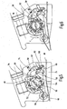
- the Fig.1 shows a perspective side view of the tensioning band device as a whole, which can be used as so-called. Umreifungs réelle. However, so far as the device is shown without the exciting band.
- the tensioning device after the Fig.1 has a designated as a whole with 10 drive unit, which drives in the actuated state, designated as a whole with 12 tape winding unit with opposite directions of rotation in one direction.
- a designated as a whole with 14 actuator which is controlled by a designated as a whole 16 control device of the tape winding unit 14, which will be shown in more detail below, is an in Fig.1 not shown, in the device insertable band 18, which is also called a strapping, releasably lock in predetermined positions.
- a cutting device designated as a whole by 20 is used for cutting off the strip 18.
- All of the above-mentioned components of the tensioning device are integrated in a clamping housing of the device designated as a whole by 22.
- the pertinent clamping housing points in the direction of the Fig.1 seen on its underside a plate-like support shoe 24, which allows it with its underside to support the device on a packaged goods and on its opposite, exposed upper surface is a guide surface 26 for the guidance of the exciting band present.
- the Fig.2 shows an end view of the clamping device according to the Fig.1 with partially cutaway clamping housing 22 for the purpose of improved representation of the interior of the device and the rest is in the illustration of the Fig.2 omitted the cutter 20, since in the pertinent basic embodiment, the device shown can also be used as a pure band tensioning device and the separation of the belt 18 can outside the device, for example with a separate Cutting device in the form of a knife (not shown), take place.
- the band 18 is in Fig.2 reproduced in a schematic representation.
- the Band18 can be a steel band, a plastic band or such with steel or plastic reinforcement and engages in the closed, in Fig.2 shown state a not-illustrated packaged goods, which is already included in the loop 30 shown. In particular, woven or glued straps are used made of synthetic fibers.
- the band 18 is usually used for standard strapping operations of a defined packaged goods, the length of the band in defined size levels is the extent given in the reason. For each type of packaged goods so far then a defined length of tape available, the packaged goods can also be multi-part, so that then over the band 18 several packaging units are held together in a composite and therefore in a lot size.
- the folded-over and tensioned band 18 also serves to stiffen the packaged goods, so that the packaging is additionally secured by the band, in particular when paperboard is used as packaging wrapping.
- the pertinent contexts are known, so that will not be discussed here at this point.
- the strips Before being processed, the strips can have a precisely defined length, which is matched to the packaged goods; but with the device according to the invention but also the use of any tape lengths is possible.
- the band 18 is looped with its one free end 32, around an eye or thimble 34 in a self-locking manner and the other free end 36 is taken after a certain number of wraps or wraps within the band winding unit 12 , As the number of Envelopes is limited, the length of the band is always such that no too many windings on the tape winding unit 12 arise, which are then no longer manageable by the device; but the tape length may not be too short, otherwise a tightening of the belt 18 and its setting on the tape winding unit 12 may be at risk.
- the eyelet or thimble 34 is tightened together with the free end of the tape 32 in the direction of arrow X on the clamping housing 22, which shortens the free length of the band strap 18 with the result that the band 18 can attach firmly to the packaged goods, not shown.
- the belt 18 can then be cut, for example, at the cutting point 38 via a separate separating or knife device, and the strapping process would then be completed.
- said belt 18 as a flat body could also be a wire-shaped body and it would also be conceivable fundamentally, a multiple superposition of bands 18 (not shown) so set on a third object, such as a packaged umNeilld. Is at the cutting point 38, the tape 18 but cut off so far, the tape 18 is held arresting in its tensioned position on the self-locking of the eyelet or clasp parts for the eyelet 34.
- control device 16 has a first control part 40 with control cam 42.
- the pertinent control cam 42 extend diametrically opposite each other about the longitudinal axis 44 of the Bandwikkelappel 12.
- a second control part 46 is provided with a further Type of control cam 48.
- the pertinent control cam 48 is present only once and extends with its outer diameter along a larger diameter pitch circle, because based on the pivoting circle of the control cam 42 in its maximum possible, pivoted position.
- Both control parts 40,46 are at least in one direction from the winding shaft 50 of the tape winding unit 12 mitEnglishbar. However, said pitch circle does not necessarily have to be larger.
- the winding shaft 50 is formed in this respect as a cylindrical driving pin and has in the middle a continuous longitudinal slot 52 which serves to entrain the end region of the other band end 36.
- a longitudinal slot also several longitudinal slots may be present. If five control cam 42 are used, a diametrically opposite arrangement is replaced by one in which the distances of the control cam 42 in the radial circumferential direction are equal to each other. In any case, preferably the control cam 42 are on the same pitch circle.
- One of the two control parts here the control part 40
- the control part 40 is provided with a freewheel device such that in one of the two possible directions of rotation, here in the direction of the Fig.2 seen, clockwise, the second control part 46 of the winding shaft 50 is entrained without power transmission or retains its assumed position.
- the control cam 42 of the control part 40 also retain the control cam 42 of the control part 40 their position shown and rotate together with the second control part 46 in the counterclockwise direction.
- the control parts 40,46 tend to be moved in the other direction, in which case the second control part 46 with its control cam 48 forms an abutment for parts of the actuator 14.
- the said freewheel device is according to the Representation after the Fig.1 realized via individual freewheel body 54, which are received in inner and outer ring parts of the clamping housing 22 and the tape winding unit 12, wherein pertinent freewheel devices are prior art, so that will not be discussed in more detail here at this point.
- the actuator 14 is composed of a multi-part lever drive consisting, wherein the angle lever designed as lever 56 is controlled by the first control part 40 with its control cam 42.
- Another lever 58 which is likewise designed in the manner of an angle lever, can be actuated by the second control part 46 with its control cam 48.
- Both levers 56,58 have to their actuation at its free end a cam roller 60 so that they better on the tracks, formed by the control cam 42,48 can slide off.
- the further lever 58 is pivotally mounted in the clamping housing 22 at its other free end via a rotation axis 62.
- a further actuating lever 64 is articulated rigid, which carries the foot-like locking device 68 for clamping or clamping the band 18 via a further joint 66.
- the locking device 68 as shown in the Fig.2 provided with a corrugation, so as to increase the engagement force in the belt surface 18.
- the lever 56 is articulated in the direction of the latter behind it via a third axis of rotation 70.
- An energy store in the form of a tension spring 72 tries to pivot the rear angle piece of the angle lever 56 about the third axis of rotation 70 in the counterclockwise direction.
- a further energy storage in the form of the compression spring 74 pushes the upper end of the lever lever 58 counterclockwise.
- the pertinent compression spring 74 is only as Functional element insofar in the Fig.2 is shown in the rest and according to the representation of the Figure 9 implemented by a leg spring 76 in the practical implementation insofar.
- tension and compression springs can also be replaced by compression or tension springs, which, however, begin at another point then obvious with their required force.
- angle lever 56 at its the cam roller 60 opposite end of a contact edge 78, which in the functional position after the Fig.2 in contact with a locking support 80 which is provided in the region of the possible sliding of the abutment edge 78 with a convex guide track 82.
- the pertinent detent support 80 is fixedly connected to the housing 22 of the tensioning device to form an abutment for said part of the lever drive and part thereof.
- the drive unit 10 preferably consists of a pneumatic motor; but could also be an electric motor or the like.
- the rod-shaped pneumatic motor discharges at its one free end face into a drive pinion 84, which meshes with an endless worm gear 86, which drives the winding shaft 50 of the tape winding unit 12, depending on the direction of rotation of the pneumatic motor counterclockwise (arrow Y). or in the opposite direction Z (s. Figure 7 ).
- the housing parts of the pneumatic motor are externally placed on the clamping housing 22 and the rotatable parts of the pneumatic motor, in particular in the form of the drive pinion 84, guided within the housing 22.
- the control cams 42 (six in total) of the first control member 40 are arranged at discrete intervals extending along a closed cam track extending concentrically to the winding shaft 50, wherein in the present embodiment, the control cam 42 to a pivot axis 88 against the action of another energy storage in the form of compression springs 90 are movable.
- Another number of control cams 42 is possible.
- the pivotal control cam 42 are held in at least the direction of rotation Y of the winding shaft 50 in a drive position for parts of the lever drive in the form of the cam roller 60 of the angle lever 56.
- the second control part 46 has, as already explained, a control cam 48, the outer peripheral side forms a kind of involute with tapered to its free end control edges 92,94, one of which 92 forms an abutment surface for parts of the lever drive in the form of the cam roller 60th for the upper angle lever 58.
- the embodiment of the Fig.2 is shown without cutting device, wherein in the Fig.2 shown arrangement is sufficient to cause a tape 18 for a fixing process can.
- a complete fixing cycle for the belt 18 is described, which, however, is shown only partially in the figures and only with its relevant areas.
- the cutting device shown in Fig.3ff is rotatable and comparable to the winding shaft 50 is formed as a hollow sleeve 96 which has a web-like protruding cutting blade 98 in the extended inner peripheral region, the free cutting edge protrudes in the direction of the continuous longitudinal slot 100, wherein the cutting blade 98 as a rotatable cutting device 20th is connected to a triangle lever 102 (see. Figure 3 ), which is controllable via a rod drive 104 via the lever drive, which engages in this respect via a lever piece 106 pivotally mounted on the longitudinal rod of the rod drive 104, wherein the rod drive 104 is articulated at its other opposite free end hinged at the end of the triangle lever 102.
- a triangle lever 102 see. Figure 3
- the hollow sleeve 96 remains in its position and the cutting blade 98 is moved via the rod drive 104 and the lever drive with the lever piece 106 counterclockwise from its cutting position after the Figure 3 in a neutral position after the Figure 5 pivoted within the hollow sleeve 96 and turn clockwise in a cutting position after the Figure 8 ,
- the cutting blade 48 is held in the cutting position and the locking device 68 is in the open position, ie the associated foot or clamping plate, as shown, lifted upwards over the lever drive.
- the drive device 10 is not actuated and the belt 18 is, which is not shown in detail, wrapped around the package or packaged goods and in the Festlegeschnalle in the form of the eyelet 34 as shown in the Fig.2 introduced.
- said tape 18 is placed on the guide surface 26 of the housing 22 by pulling the tape 18 between the locking device 68 and the guide surface 26. The upper free end of the tape is not yet introduced in the said fixture.
- the drive unit 10 is turned on and it comes to the direction of rotation Y in the counterclockwise direction. Due to the worm drive in the form of the endless screw 86, the pertinent direction of rotation is counterclockwise, in which case the winding shaft 50 is then taken counterclockwise rotating.
- the control cam 42 hinged to the disk-shaped first control part 40 actuate the angle lever 56 via its projecting guide roller 60.
- the abutment edge 78 of the angle lever 56 is first along the concave frontal trajectory of the locking support 80 out to a sub-grip point, in which then sliding along along the lower convex track course 82 of said locking support 80 is caused; a movement which is supported by the Glasfederantechnisch 72, wherein the tension spring 72 is articulated once with its two free ends on the actuating lever 64 and once on the angle lever 56 in the region of the attack flank 78.
- the switching on and off of the drive unit 10 in the form of the pneumatic motor is done by means not shown actuators, but to that extent allow one-handed operation for the entire clamping device, and for each direction of rotation of the drive unit 10 is provided on the direction indicative actuating knob preferably.
- the cutting blade 98 is pivoted over the triangle lever 102 in a clockwise direction via the rod drive 104 and so in his in the Figure 8 brought shown cutting position.
- the band 18 at the end.
- the cam roller 60 of the angle lever 56 sliding past, spring-loaded control cam 42 are so far folded away against the spring force or swung away and hinder the extent not the release process for the band.
- the tensioning device can be removed. As shown in the Figure 8 on the winding shaft 50 remaining tape residue can then be removed by hand readily.
- the band tensioning device then stands for a new tensioning operation according to its starting position after Figure 3 to disposal.
- a variant according to the Fig. 10 to 13 is the disc-shaped control part 40, which cooperates with the winding shaft 50, provided with fixed control cam 42a instead of the spring-loaded, movable control cam 42.
- another angle lever 108 is provided in addition to the already described angle lever 56 , which has the same pivot axis 70 to the lever 56 and the rest at its free end with an over-grip piece 110 (see. Figure 12 ) the other angle 56 in the area of the abutment edge 78 engages over the end.
- the angle lever 108 is held by a further tension spring 112.
- control disk as the first control part 40 with this firmly connected in the direction of the FIGS. 14 and 16 seen rearwardly projecting control cam 42b. If in turn, as already explained, the drive unit 10 is turned on, the direction of rotation Y should result and the winding shaft 50 thus rotates counterclockwise.
- the driving plate 114 which is fixedly connected to the winding shaft 50 is used.
- An actuating disk 116 which is rotatably guided on the winding shaft by means of a conventional bearing 118, which is provided with a freewheel, has a spring-loaded actuating pin 120, which in the direction of the FIGS.
Landscapes
- Engineering & Computer Science (AREA)
- Mechanical Engineering (AREA)
- Basic Packing Technique (AREA)
- Power Steering Mechanism (AREA)
Claims (9)
- Installation pour tendre une bande, notamment banderoleuse, comprenant un groupe (10) d'entraînement, qui, à l'état actionné, entraîne une unité (12) d'enroulement de bande ayant des sens de rotation opposés dans respectivement un sens, dans laquelle, au moyen d'un dispositif (14) d'actionnement, qui peut être commandé par un dispositif (16) de commande de l'unité (12) d'enroulement de bande, la bande (18), qui peut être mise dans l'installation, peut être bloquée d'une manière amovible dans des positions pouvant être prescrites, caractérisée en ce que le dispositif (16) de commande comporte une première partie de commande ayant des cames (42) de commande ainsi qu'une deuxième partie (46) de commande ayant au moins une autre came (48) de commande, en ce que les deux parties (40, 46) de commande peuvent être entraînées, au moins dans un sens par l'arbre (50) d'enroulement de l'unité (12) d'enroulement de bande, et en ce qu'au moins l'une (46) des deux parties (40, 46) de commande est pourvue d'un dispositif (54) à roue libre, de manière à ce que, dans l'un des deux sens de rotation possibles, ladite partie (46) de commande puisse être entraînée par l'arbre (50) d'enroulement sans transmission de force et/ou de manière à ce que celui-ci reste dans sa position d'entraînement.
- Installation suivant la revendication 1, caractérisée en ce que le dispositif (14) d'actionnement est constitué d'un mécanisme de levier en plusieurs parties, en ce qu'au moins un levier (56) du mécanisme peut être commandé par la première partie (40) de commande et au moins un autre levier (58) par la deuxième partie (46) de commande et en ce qu'il est prévu à une extrémité libre du mécanisme de levier une partie d'un dispositif (68) de blocage, qui bloque de manière amovible en les positions prescrites la bande (18), qui peut être mise dans l'installation.
- Installation suivant la revendication 1 ou 2, caractérisée en ce que les cames (42) de commande de la première partie (40) de commande s'étendent à des distances discrètes les unes des autres le long d'une trajectoire courbe fermée, qui est concentrique à l'arbre (50) d'enroulement, et en ce que les cames (42a, 42b) de commande sont au moins en partie des éléments constitutifs rigides d'un disque (114) de commande ou en ce que les cames (42) de commande sont maintenues, dans au moins un sens (Y) de rotation de l'arbre (50) d'enroulement, dans une position de commande des pièces (60, 56) du mécanisme de levier en étant mobiles au moins en partie à l'encontre de l'action d'un accumulateur (90) d'énergie.
- Installation suivant l'une des revendications 1 à 3, caractérisée en ce que la deuxième partie (46) de commande comporte au moins une came (48) de commande ayant des flancs (92, 94) de commande se rétrécissant coniquement à son extrémité libre et dont l'un (92) forme une surface de butée pour des parties (60, 58) du mécanisme de levier.
- Installation suivant l'une des revendications 1 à 4, caractérisée en ce que les éléments mobiles sont intégrés au moins en partie dans une enveloppe (22) pouvant être manipulée et ayant dans la partie du mécanisme de levier un cliquet (80) d'encliquetage, qui forme une butée pour une partie (78) du mécanisme de levier dès que ladite partie (78) attaque le cliquet (80) d'encliquetage.
- Installation suivant l'une des revendications 1 à 4, caractérisée en ce que des parties (56, 58) du mécanisme de levier sont maintenues en utilisant au moins un autre accumulateur (72, 74) d'énergie dans leur position d'application efficace par le dispositif (42, 46) de commande.
- Installation suivant l'une des revendications 1 à 6, caractérisée en ce que celle-ci est pourvue d'un dispositif (20) tournant de coupe de la bande (18), qui peut être guidée dans un guidage (100) à fente, lequel permet, en étant muni d'au moins une lame (98) de coupe, de séparer la bande (18) dans une position en rotation.
- Installation suivant la revendication 7, caractérisée en ce que, pour entraîner le dispositif (20) de coupe tournant, on se sert d'une tringlerie (104), qui peut être actionnée par le mécanisme à levier.
- Installation suivant l'une des revendications 1 à 8, caractérisée en ce qu'il est prévu comme groupe (10) d'entraînement un moteur pneumatique ayant deux sens de rotation opposés, qui coopèrent avec l'unité (12) d'enroulement de bande par un engrenage à vis sans fin.
Applications Claiming Priority (2)
| Application Number | Priority Date | Filing Date | Title |
|---|---|---|---|
| DE102006010912A DE102006010912A1 (de) | 2006-03-09 | 2006-03-09 | Vorrichtung zum Spannen eines Bandes |
| PCT/EP2007/001663 WO2007101583A1 (fr) | 2006-03-09 | 2007-02-27 | Dispositif pour serrer une bande |
Publications (2)
| Publication Number | Publication Date |
|---|---|
| EP1991464A1 EP1991464A1 (fr) | 2008-11-19 |
| EP1991464B1 true EP1991464B1 (fr) | 2011-03-23 |
Family
ID=38051781
Family Applications (1)
| Application Number | Title | Priority Date | Filing Date |
|---|---|---|---|
| EP07711682A Not-in-force EP1991464B1 (fr) | 2006-03-09 | 2007-02-27 | Dispotif puor serrer une bande |
Country Status (5)
| Country | Link |
|---|---|
| US (1) | US7669526B2 (fr) |
| EP (1) | EP1991464B1 (fr) |
| AT (1) | ATE502854T1 (fr) |
| DE (2) | DE102006010912A1 (fr) |
| WO (1) | WO2007101583A1 (fr) |
Families Citing this family (6)
| Publication number | Priority date | Publication date | Assignee | Title |
|---|---|---|---|---|
| KR200453169Y1 (ko) | 2008-10-24 | 2011-04-11 | 대우조선해양 주식회사 | 선박용 케이블 타이 결속장치 |
| US9789984B2 (en) | 2012-07-05 | 2017-10-17 | Golden Bear LLC | Externally-powered strapping tool and a strapping tool assembly utilized therein |
| US10604286B2 (en) * | 2014-05-08 | 2020-03-31 | Encore Packaging Llc | Tool for tightening strapping |
| WO2019104333A1 (fr) * | 2017-11-27 | 2019-05-31 | Ideal Industries, Inc. | Appareil pour tendre un dispositif de bande d'entrelacement de câbles |
| US11066200B2 (en) * | 2017-11-27 | 2021-07-20 | Daniels Manufacturing Corporation | Apparatus for tensioning a cable lacing tape device |
| TWM585235U (zh) * | 2019-05-10 | 2019-10-21 | 長諺工業股份有限公司 | 具有減速裝置的打包機 |
Family Cites Families (10)
| Publication number | Priority date | Publication date | Assignee | Title |
|---|---|---|---|---|
| US3189060A (en) * | 1962-04-03 | 1965-06-15 | Fmc Corp | Strap tensioning tool |
| DK214079A (da) * | 1978-05-25 | 1979-11-26 | Gerrard Ind Ltd | Emballageombindingsvaerktoej |
| US4252158A (en) * | 1979-07-06 | 1981-02-24 | Fmc Corporation | Strap tensioning tool |
| WO1984000023A1 (fr) * | 1982-06-15 | 1984-01-05 | Andras Banai | Appareil manuel pour le serrage des bandes pour lier des objets |
| US4605456A (en) * | 1985-05-02 | 1986-08-12 | Signode Corporation | Method and apparatus for feeding and tensioning strap in a strapping machine |
| ATE95475T1 (de) * | 1988-09-08 | 1993-10-15 | Strapex Ag | Spann- und verschliessgeraet fuer ein umreifungsband aus kunststoff. |
| US6131634A (en) | 1999-05-27 | 2000-10-17 | Chang; Jeff Chieh Huang | Portable strapping apparatus |
| DE10026200A1 (de) | 2000-05-26 | 2001-11-29 | Cyklop Gmbh | Vorrichtung zum Spannen von Umreifungsbändern |
| US6708606B1 (en) * | 2002-10-31 | 2004-03-23 | Illinois Tool Works, Inc. | Strapper with improved winder |
| US6962108B1 (en) * | 2004-06-23 | 2005-11-08 | Hsiu-Man Yu Chen | Strap-guiding device for a strapping packaging apparatus |
-
2006
- 2006-03-09 DE DE102006010912A patent/DE102006010912A1/de not_active Withdrawn
-
2007
- 2007-02-27 EP EP07711682A patent/EP1991464B1/fr not_active Not-in-force
- 2007-02-27 US US12/224,714 patent/US7669526B2/en active Active
- 2007-02-27 AT AT07711682T patent/ATE502854T1/de active
- 2007-02-27 DE DE502007006771T patent/DE502007006771D1/de active Active
- 2007-02-27 WO PCT/EP2007/001663 patent/WO2007101583A1/fr active Application Filing
Also Published As
| Publication number | Publication date |
|---|---|
| WO2007101583A1 (fr) | 2007-09-13 |
| DE502007006771D1 (de) | 2011-05-05 |
| EP1991464A1 (fr) | 2008-11-19 |
| US20090071350A1 (en) | 2009-03-19 |
| ATE502854T1 (de) | 2011-04-15 |
| US7669526B2 (en) | 2010-03-02 |
| DE102006010912A1 (de) | 2007-09-13 |
Similar Documents
| Publication | Publication Date | Title |
|---|---|---|
| DE3102242C2 (fr) | ||
| EP1283797B1 (fr) | Dispositif pour tendre des bandes de cerclage | |
| EP1991464B1 (fr) | Dispotif puor serrer une bande | |
| EP0075252B1 (fr) | Dispositif de liage automatique pour une machine à former des balles de fourrage cylindriques | |
| DE102005013901A1 (de) | Baumständer, insbesondere Christbaumständer mit verbesserter Lösefunktion | |
| DE2628608C3 (de) | Vorrichtung zum Umbinden eines Gegenstandes | |
| DE19705584B4 (de) | Garnsicherungsvorrichtung | |
| DE2165664C3 (de) | Vorrichtung zum Umbinden von mehreren Gegenständen mit einer Bandschlaufe | |
| DE3644657C2 (fr) | ||
| DE1427620A1 (de) | Vorrichtung zum Aufbringen von Haftfolien | |
| DE3337184A1 (de) | Aufwickel- und spannvorrichtung fuer ein lasthalteband | |
| DE2910989C2 (de) | Zangenartiges Werkzeug zum Anbinden der Triebe von Kulturgehölzen | |
| WO2000073187A1 (fr) | Distributeur de ruban | |
| DE3536955A1 (de) | Vorrichtung zum buendeln oder umwickeln von laenglichen dingen | |
| DE3638882C2 (fr) | ||
| DE102011076278B4 (de) | Abbindevorrichtung für Pressballen | |
| DE602004006616T2 (de) | Vorrichtung zum anbringen von bindfäden an süssigkeiten | |
| DE1586502C (de) | Spannvorrichtung für Bander, insbe sondere aus Kunststoff, Textilien u dgl | |
| DE1486185C (de) | Maschine zum Umschnüren von Packstucken | |
| DE1586203C (de) | Vorrichtung zur Führung eines Bandes, insbesondere an der Verbindungsstelle von Bandanfang und Bandende bei einer Verschnürungsmaschine | |
| DE934795C (de) | Bindemechanismus fuer Ballenpressen | |
| DE1761124C (de) | Spann- und Schließ werkzeug für Verpackungsbänder | |
| DE1535891C (de) | Knüpfgerät zum Verknoten von Faden | |
| DE430029C (de) | Vorrichtung zum Verschnueren von Kisten, Ballen o. dgl. mittels eines Drahtes | |
| WO2010128103A1 (fr) | Machine à ligaturer portable |
Legal Events
| Date | Code | Title | Description |
|---|---|---|---|
| PUAI | Public reference made under article 153(3) epc to a published international application that has entered the european phase |
Free format text: ORIGINAL CODE: 0009012 |
|
| 17P | Request for examination filed |
Effective date: 20080724 |
|
| AK | Designated contracting states |
Kind code of ref document: A1 Designated state(s): AT BE BG CH CY CZ DE DK EE ES FI FR GB GR HU IE IS IT LI LT LU LV MC NL PL PT RO SE SI SK TR |
|
| 17Q | First examination report despatched |
Effective date: 20090707 |
|
| GRAP | Despatch of communication of intention to grant a patent |
Free format text: ORIGINAL CODE: EPIDOSNIGR1 |
|
| GRAS | Grant fee paid |
Free format text: ORIGINAL CODE: EPIDOSNIGR3 |
|
| GRAA | (expected) grant |
Free format text: ORIGINAL CODE: 0009210 |
|
| AK | Designated contracting states |
Kind code of ref document: B1 Designated state(s): AT BE BG CH CY CZ DE DK EE ES FI FR GB GR HU IE IS IT LI LT LU LV MC NL PL PT RO SE SI SK TR |
|
| REG | Reference to a national code |
Ref country code: GB Ref legal event code: FG4D Free format text: NOT ENGLISH |
|
| REG | Reference to a national code |
Ref country code: CH Ref legal event code: NV Representative=s name: ISLER & PEDRAZZINI AG Ref country code: CH Ref legal event code: EP |
|
| REG | Reference to a national code |
Ref country code: IE Ref legal event code: FG4D |
|
| REF | Corresponds to: |
Ref document number: 502007006771 Country of ref document: DE Date of ref document: 20110505 Kind code of ref document: P |
|
| REG | Reference to a national code |
Ref country code: DE Ref legal event code: R096 Ref document number: 502007006771 Country of ref document: DE Effective date: 20110505 |
|
| REG | Reference to a national code |
Ref country code: NL Ref legal event code: T3 |
|
| REG | Reference to a national code |
Ref country code: GR Ref legal event code: EP Ref document number: 20110401141 Country of ref document: GR Effective date: 20110614 |
|
| PG25 | Lapsed in a contracting state [announced via postgrant information from national office to epo] |
Ref country code: LT Free format text: LAPSE BECAUSE OF FAILURE TO SUBMIT A TRANSLATION OF THE DESCRIPTION OR TO PAY THE FEE WITHIN THE PRESCRIBED TIME-LIMIT Effective date: 20110323 Ref country code: LV Free format text: LAPSE BECAUSE OF FAILURE TO SUBMIT A TRANSLATION OF THE DESCRIPTION OR TO PAY THE FEE WITHIN THE PRESCRIBED TIME-LIMIT Effective date: 20110323 Ref country code: SE Free format text: LAPSE BECAUSE OF FAILURE TO SUBMIT A TRANSLATION OF THE DESCRIPTION OR TO PAY THE FEE WITHIN THE PRESCRIBED TIME-LIMIT Effective date: 20110323 |
|
| LTIE | Lt: invalidation of european patent or patent extension |
Effective date: 20110323 |
|
| PG25 | Lapsed in a contracting state [announced via postgrant information from national office to epo] |
Ref country code: SI Free format text: LAPSE BECAUSE OF FAILURE TO SUBMIT A TRANSLATION OF THE DESCRIPTION OR TO PAY THE FEE WITHIN THE PRESCRIBED TIME-LIMIT Effective date: 20110323 Ref country code: BG Free format text: LAPSE BECAUSE OF FAILURE TO SUBMIT A TRANSLATION OF THE DESCRIPTION OR TO PAY THE FEE WITHIN THE PRESCRIBED TIME-LIMIT Effective date: 20110623 Ref country code: CY Free format text: LAPSE BECAUSE OF FAILURE TO SUBMIT A TRANSLATION OF THE DESCRIPTION OR TO PAY THE FEE WITHIN THE PRESCRIBED TIME-LIMIT Effective date: 20110323 Ref country code: FI Free format text: LAPSE BECAUSE OF FAILURE TO SUBMIT A TRANSLATION OF THE DESCRIPTION OR TO PAY THE FEE WITHIN THE PRESCRIBED TIME-LIMIT Effective date: 20110323 |
|
| REG | Reference to a national code |
Ref country code: IE Ref legal event code: FD4D |
|
| PG25 | Lapsed in a contracting state [announced via postgrant information from national office to epo] |
Ref country code: EE Free format text: LAPSE BECAUSE OF FAILURE TO SUBMIT A TRANSLATION OF THE DESCRIPTION OR TO PAY THE FEE WITHIN THE PRESCRIBED TIME-LIMIT Effective date: 20110323 Ref country code: PT Free format text: LAPSE BECAUSE OF FAILURE TO SUBMIT A TRANSLATION OF THE DESCRIPTION OR TO PAY THE FEE WITHIN THE PRESCRIBED TIME-LIMIT Effective date: 20110725 |
|
| PG25 | Lapsed in a contracting state [announced via postgrant information from national office to epo] |
Ref country code: ES Free format text: LAPSE BECAUSE OF FAILURE TO SUBMIT A TRANSLATION OF THE DESCRIPTION OR TO PAY THE FEE WITHIN THE PRESCRIBED TIME-LIMIT Effective date: 20110704 Ref country code: IS Free format text: LAPSE BECAUSE OF FAILURE TO SUBMIT A TRANSLATION OF THE DESCRIPTION OR TO PAY THE FEE WITHIN THE PRESCRIBED TIME-LIMIT Effective date: 20110723 Ref country code: RO Free format text: LAPSE BECAUSE OF FAILURE TO SUBMIT A TRANSLATION OF THE DESCRIPTION OR TO PAY THE FEE WITHIN THE PRESCRIBED TIME-LIMIT Effective date: 20110323 Ref country code: CZ Free format text: LAPSE BECAUSE OF FAILURE TO SUBMIT A TRANSLATION OF THE DESCRIPTION OR TO PAY THE FEE WITHIN THE PRESCRIBED TIME-LIMIT Effective date: 20110323 Ref country code: SK Free format text: LAPSE BECAUSE OF FAILURE TO SUBMIT A TRANSLATION OF THE DESCRIPTION OR TO PAY THE FEE WITHIN THE PRESCRIBED TIME-LIMIT Effective date: 20110323 |
|
| PLBE | No opposition filed within time limit |
Free format text: ORIGINAL CODE: 0009261 |
|
| STAA | Information on the status of an ep patent application or granted ep patent |
Free format text: STATUS: NO OPPOSITION FILED WITHIN TIME LIMIT |
|
| PG25 | Lapsed in a contracting state [announced via postgrant information from national office to epo] |
Ref country code: IE Free format text: LAPSE BECAUSE OF FAILURE TO SUBMIT A TRANSLATION OF THE DESCRIPTION OR TO PAY THE FEE WITHIN THE PRESCRIBED TIME-LIMIT Effective date: 20110323 |
|
| 26N | No opposition filed |
Effective date: 20111227 |
|
| PG25 | Lapsed in a contracting state [announced via postgrant information from national office to epo] |
Ref country code: PL Free format text: LAPSE BECAUSE OF FAILURE TO SUBMIT A TRANSLATION OF THE DESCRIPTION OR TO PAY THE FEE WITHIN THE PRESCRIBED TIME-LIMIT Effective date: 20110323 Ref country code: DK Free format text: LAPSE BECAUSE OF FAILURE TO SUBMIT A TRANSLATION OF THE DESCRIPTION OR TO PAY THE FEE WITHIN THE PRESCRIBED TIME-LIMIT Effective date: 20110323 |
|
| REG | Reference to a national code |
Ref country code: DE Ref legal event code: R097 Ref document number: 502007006771 Country of ref document: DE Effective date: 20111227 |
|
| BERE | Be: lapsed |
Owner name: GREINER G.M.B.H. & CO. KG Effective date: 20120228 |
|
| PG25 | Lapsed in a contracting state [announced via postgrant information from national office to epo] |
Ref country code: MC Free format text: LAPSE BECAUSE OF NON-PAYMENT OF DUE FEES Effective date: 20120229 |
|
| PG25 | Lapsed in a contracting state [announced via postgrant information from national office to epo] |
Ref country code: BE Free format text: LAPSE BECAUSE OF NON-PAYMENT OF DUE FEES Effective date: 20120228 |
|
| REG | Reference to a national code |
Ref country code: AT Ref legal event code: MM01 Ref document number: 502854 Country of ref document: AT Kind code of ref document: T Effective date: 20120227 |
|
| PG25 | Lapsed in a contracting state [announced via postgrant information from national office to epo] |
Ref country code: AT Free format text: LAPSE BECAUSE OF NON-PAYMENT OF DUE FEES Effective date: 20120227 |
|
| PG25 | Lapsed in a contracting state [announced via postgrant information from national office to epo] |
Ref country code: TR Free format text: LAPSE BECAUSE OF FAILURE TO SUBMIT A TRANSLATION OF THE DESCRIPTION OR TO PAY THE FEE WITHIN THE PRESCRIBED TIME-LIMIT Effective date: 20110323 |
|
| PG25 | Lapsed in a contracting state [announced via postgrant information from national office to epo] |
Ref country code: LU Free format text: LAPSE BECAUSE OF NON-PAYMENT OF DUE FEES Effective date: 20120227 |
|
| PG25 | Lapsed in a contracting state [announced via postgrant information from national office to epo] |
Ref country code: HU Free format text: LAPSE BECAUSE OF FAILURE TO SUBMIT A TRANSLATION OF THE DESCRIPTION OR TO PAY THE FEE WITHIN THE PRESCRIBED TIME-LIMIT Effective date: 20070227 |
|
| REG | Reference to a national code |
Ref country code: FR Ref legal event code: PLFP Year of fee payment: 10 |
|
| REG | Reference to a national code |
Ref country code: FR Ref legal event code: PLFP Year of fee payment: 11 |
|
| REG | Reference to a national code |
Ref country code: FR Ref legal event code: PLFP Year of fee payment: 12 |
|
| PGFP | Annual fee paid to national office [announced via postgrant information from national office to epo] |
Ref country code: GB Payment date: 20200218 Year of fee payment: 14 Ref country code: GR Payment date: 20200128 Year of fee payment: 14 |
|
| PGFP | Annual fee paid to national office [announced via postgrant information from national office to epo] |
Ref country code: CH Payment date: 20200128 Year of fee payment: 14 |
|
| PGFP | Annual fee paid to national office [announced via postgrant information from national office to epo] |
Ref country code: FR Payment date: 20200214 Year of fee payment: 14 |
|
| GBPC | Gb: european patent ceased through non-payment of renewal fee |
Effective date: 20210227 |
|
| PG25 | Lapsed in a contracting state [announced via postgrant information from national office to epo] |
Ref country code: LI Free format text: LAPSE BECAUSE OF NON-PAYMENT OF DUE FEES Effective date: 20210228 Ref country code: CH Free format text: LAPSE BECAUSE OF NON-PAYMENT OF DUE FEES Effective date: 20210228 |
|
| PG25 | Lapsed in a contracting state [announced via postgrant information from national office to epo] |
Ref country code: GR Free format text: LAPSE BECAUSE OF NON-PAYMENT OF DUE FEES Effective date: 20210906 |
|
| PG25 | Lapsed in a contracting state [announced via postgrant information from national office to epo] |
Ref country code: FR Free format text: LAPSE BECAUSE OF NON-PAYMENT OF DUE FEES Effective date: 20210228 Ref country code: GB Free format text: LAPSE BECAUSE OF NON-PAYMENT OF DUE FEES Effective date: 20210227 |
|
| PGFP | Annual fee paid to national office [announced via postgrant information from national office to epo] |
Ref country code: DE Payment date: 20220228 Year of fee payment: 16 |
|
| PGFP | Annual fee paid to national office [announced via postgrant information from national office to epo] |
Ref country code: NL Payment date: 20220221 Year of fee payment: 16 Ref country code: IT Payment date: 20220210 Year of fee payment: 16 |
|
| REG | Reference to a national code |
Ref country code: DE Ref legal event code: R119 Ref document number: 502007006771 Country of ref document: DE |
|
| REG | Reference to a national code |
Ref country code: NL Ref legal event code: MM Effective date: 20230301 |
|
| PG25 | Lapsed in a contracting state [announced via postgrant information from national office to epo] |
Ref country code: NL Free format text: LAPSE BECAUSE OF NON-PAYMENT OF DUE FEES Effective date: 20230301 |
|
| PG25 | Lapsed in a contracting state [announced via postgrant information from national office to epo] |
Ref country code: IT Free format text: LAPSE BECAUSE OF NON-PAYMENT OF DUE FEES Effective date: 20230227 Ref country code: DE Free format text: LAPSE BECAUSE OF NON-PAYMENT OF DUE FEES Effective date: 20230901 |