EP1991448B1 - Sicherheitsanordnung in einem fahrzeugsitz - Google Patents
Sicherheitsanordnung in einem fahrzeugsitz Download PDFInfo
- Publication number
- EP1991448B1 EP1991448B1 EP07723109A EP07723109A EP1991448B1 EP 1991448 B1 EP1991448 B1 EP 1991448B1 EP 07723109 A EP07723109 A EP 07723109A EP 07723109 A EP07723109 A EP 07723109A EP 1991448 B1 EP1991448 B1 EP 1991448B1
- Authority
- EP
- European Patent Office
- Prior art keywords
- airbag
- seat
- support plate
- seat frame
- safety device
- Prior art date
- Legal status (The legal status is an assumption and is not a legal conclusion. Google has not performed a legal analysis and makes no representation as to the accuracy of the status listed.)
- Active
Links
- 239000004744 fabric Substances 0.000 claims description 6
- 238000009423 ventilation Methods 0.000 claims description 2
- 210000004197 pelvis Anatomy 0.000 description 10
- 230000000694 effects Effects 0.000 description 6
- 210000002105 tongue Anatomy 0.000 description 6
- 239000002184 metal Substances 0.000 description 4
- 238000011161 development Methods 0.000 description 3
- 230000018109 developmental process Effects 0.000 description 3
- 239000000853 adhesive Substances 0.000 description 2
- 230000001070 adhesive effect Effects 0.000 description 2
- 230000014759 maintenance of location Effects 0.000 description 2
- 238000004519 manufacturing process Methods 0.000 description 2
- 230000000630 rising effect Effects 0.000 description 2
- 230000004913 activation Effects 0.000 description 1
- 230000001174 ascending effect Effects 0.000 description 1
- 238000005452 bending Methods 0.000 description 1
- 239000011248 coating agent Substances 0.000 description 1
- 238000000576 coating method Methods 0.000 description 1
- 238000010276 construction Methods 0.000 description 1
- 238000006073 displacement reaction Methods 0.000 description 1
- 239000000835 fiber Substances 0.000 description 1
- 239000007769 metal material Substances 0.000 description 1
- 230000002093 peripheral effect Effects 0.000 description 1
- 239000003380 propellant Substances 0.000 description 1
- 230000035484 reaction time Effects 0.000 description 1
- 230000002787 reinforcement Effects 0.000 description 1
- 230000000284 resting effect Effects 0.000 description 1
- 230000000452 restraining effect Effects 0.000 description 1
- 238000005096 rolling process Methods 0.000 description 1
- 238000007789 sealing Methods 0.000 description 1
- 238000009958 sewing Methods 0.000 description 1
- 125000006850 spacer group Chemical group 0.000 description 1
- 238000013022 venting Methods 0.000 description 1
Images


Classifications
-
- B—PERFORMING OPERATIONS; TRANSPORTING
- B60—VEHICLES IN GENERAL
- B60R—VEHICLES, VEHICLE FITTINGS, OR VEHICLE PARTS, NOT OTHERWISE PROVIDED FOR
- B60R21/00—Arrangements or fittings on vehicles for protecting or preventing injuries to occupants or pedestrians in case of accidents or other traffic risks
- B60R21/02—Occupant safety arrangements or fittings, e.g. crash pads
- B60R21/16—Inflatable occupant restraints or confinements designed to inflate upon impact or impending impact, e.g. air bags
- B60R21/20—Arrangements for storing inflatable members in their non-use or deflated condition; Arrangement or mounting of air bag modules or components
- B60R21/207—Arrangements for storing inflatable members in their non-use or deflated condition; Arrangement or mounting of air bag modules or components in vehicle seats
Definitions
- the invention relates to a safety arrangement in a vehicle seat with a seat frame, on which a seat cushion is mounted, and an airbag unit with a gas generator and a gas bag, which is arranged below the seat cushion on the seat frame.
- a vehicle seat is known with an airbag unit in which a support plate is mounted in a seat frame. Within the carrier plate, a folded airbag is mounted in a bulge. The folded airbag fills this bulge and forms a plane together with the support plate.
- an assigned gas generator is activated and Fills the gas bag with gas. This lifts a seat cushion and reduces or eliminates the "submarining" effect.
- GAB 2,385,028 describes an inflatable safety assembly having an inflatable unit of at least one preformed, plastically deformable member formed as part of an edge of an inflatable chamber. As soon as a gas generator is activated, an initially folded-in projection is slipped outward.
- the inflatable element may be constructed of plastic or metal.
- a so-called pelvic restraining cushion forms an increase substantially across the entire width in the front region of the seat cushion, in order to minimize the risk of slippage,
- the US 2004/155446 relates to a generic safety device for a vehicle user in which an inflatable belt is placed on a base plate.
- the inflatable belt is covered by a seat cushion.
- the inflatable belt is surrounded by a folded metal plate that deforms when the belt is inflated.
- the inflatable devices of the prior art must either be elaborately folded or preformed, which makes a production and assembly relatively complex and costly.
- the object of the present invention is to provide a safety device in a vehicle seat which effectively avoids slippage of the seat occupant in the event of an accident and at the same time is easy to assemble and manufacture,
- the safety device in a vehicle with a seat frame on which a seat cushion is mounted, and an airbag unit with a gas generator and a gas bag, which are arranged below the seat cushion on the seat frame, provides that the Crassack unfolded and flat in the non-activated state the seat frame or a support rests.
- the gas bag which is located in the front area of the seat cushion below a
- Padding flat on the seat frame prevents the "submarining" of a seat occupant when inflated and reduces the displacement of the pelvis in an accident. This allows the pelvis to be effectively restrained in an accident by the seat belt system.
- a lower load on the pelvis is exercised by the lap belt.
- the load on the pelvis from the seat is reduced as the pelvis is displaced forward.
- the unfolded arrangement of the airbag has a simplification of the assembly and a faster inflation of the airbag result, which can reduce the reaction times.
- the unfolded airbag takes up less space and increases the design freedom in the seat construction.
- a development of the invention provides that a support plate covers at least a portion of the airbag in the non-activated state relative to the seat cushion to protect the airbag from damage when it is mounted below the seat cushion. This prevents the gas bag from being damaged by the movements of the seat occupant on the seat cushion.
- the support plate is a part of the seat frame or the support and be formed from a plastic or sheet metal material.
- the support plate is biased by a spring, in particular a torsion spring in the direction of the gas bag, so that the support plate rests like a lid on the flat gas bag.
- the seat frame has a plate-shaped support for the gas bag, on which rests.
- This plate-shaped support is preferably formed inclined inclined in the direction of the seat leading edge rising to provide a passive element to support the "anti-submarine”.
- the gas generator is preferably mounted on the seat frame, in particular below the seat frame and is preferably located in the immediate vicinity of the gas bag mounted flat on the support or the seat frame.
- the gas generator is attached to the seat frame or the plate-shaped support via fastening bolts, screws or the like, alternatively, the gas generator may also be welded.
- the support plate is folded or folded in the direction of the gas bag and can be attached or arranged on the seat frame or on the support plate.
- a one-piece embodiment of the support plate it is provided that there is a film-hinge-like connection at the bend line or fold line.
- the support plate is hinged to the seat frame, for example by tabs are inserted into recesses and optionally bent.
- the seat frame or the support plate may form a housing for the gas generator, so that the gas generator can be inserted only in this housing and fastened by fastening means, such as screws or mounting bolts, to the support plate or the seat frame.
- the support plate is a separate component, which also forms a housing for the gas generator, with a prefastened gas bag, for example, has holes on its periphery outside a circumferential seam and hooked into hooks or the like and attached.
- the support plate which is designed to support the ramp-like configuration of the front portion of the seat frame, may be resiliently biased in directions toward the gas bag to securely hold it in place in the non-activated state.
- the gas bag may have vent openings, preferably in slot shape, to effect a controlled escape of the deployment gas provided by the inflator.
- the support plate which rests in the activated state of the airbag thereto, have ventilation openings, which are preferably arranged corresponding to the vents of the airbag, so that the support plate does not obstruct the venting of the inflated airbag unduly.
- the airbag is preferably made of a fabric that may be wholly or partially coated, whereby the mass and weight can be reduced in comparison to the known unfolding of metal or plastic. At the same time the height is reduced compared to the usual facilities.
- the gas generator may be a compressed air tank or a pyrotechnic gas generator.
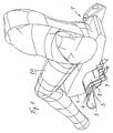
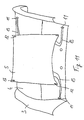
- FIG. 1 is schematically illustrated a vehicle seat 1 without a backrest.
- a seat occupant 20 On the vehicle seat 1 is a seat occupant 20, which is also shown only partially schematically.
- the vehicle seat 1 has a seat cushion 2 which is fastened on a seat frame 3.
- the seat frame 3 forms a support plate 4 or receives such a support plate 4, which extends in the front report of the vehicle seat 1 in the direction of the front seat edge rising.
- a gas bag 5 is placed flat, which extends substantially over the entire seat width.
- the gas bag 5 can be operated with a pressure between 3 and 5 bar and is preferably designed as a single-chamber gas bag.
- the gas bag 5 may be formed from two fabric blanks, which are sewn together by a peripheral seam, or as an integrally woven airbag.
- the weave of the fibers of the fabric of the airbag extends in and perpendicular to the direction of travel and preferably crosses at a right angle.
- the fabric is partially or completely coated to be resistant to a hot gas introduced from a gas generator 6 in the event of an accident in the gas bag 5.
- the coating can achieve an additional sealing effect.
- a support plate 8 is formed and arranged, which corresponds substantially to the ascending contour of the support plate 4.
- the support plate 8 is connected via a hinge 9, for example a kind of film hinge or another joint, with the seat frame 3 or with the support plate 4.
- Both the support plate 4 and the support plate 8 form a housing 10 for receiving the gas generator 6.
- the support plate 8 can be hooked, placed on or bent over.
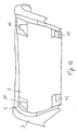
- FIG. 2 shows in bottom view the seat cushion of the seat 1 according to the FIG. 1 ,
- the seat frame 3 with the obliquely upwardly directed support plate 4 and the seat cushion disposed above can be seen as well as the Housing 10, which is formed as part of the support plate 4 and the seat frame 3.
- Mounting flanges 14 are used for attachment of the gas generator or the seat cushion.
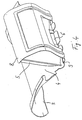
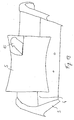
- FIG. 3 is a detailed representation of the seat base with the seat frame 3, the flat on the support plate 4 arranged airbag 5 and the overlying support plate to recognize.
- the gas bag 5 is attached to the gas generator 6 and is held by the latter in the event of inflation to the seat frame 3 and on the support plate 4.
- the gas generator via fastening tabs 7 on the seat frame 3 and the integrally formed therewith support plate 4 is attached.
- FIG. 4 is the seat bottom according to FIG. 3 shown in the unfolded state of the airbag 5.
- a sensor signal was forwarded to the gas generator via a control device, which then activated either the stored pressure medium or the pyrotechnic propellant charge.
- the gas bag 5 was inflated and the support plate 8 erected and displaced upwards. A forward moving pool of the seat occupant would be pressed against the support plate 8 in this state.
- a Nachvorne Obsten of the pelvis was thereby effectively prevented, as well as a Unter prepare for the pelvis under a lap belt, not shown.
- the support plate 8 is pivotally connected via the hinge 9 with support plate 4 and supports and keeps the airbag 5 after activation in the desired state.
- the support plate 8 forms a part of the housing, as well as the support plate. 4
- openings may be provided corresponding to the vents in the gas bag to allow a gas outlet.
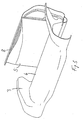
- FIG. 5 shows the state according to FIG. 4 from another view, namely from diagonally forward.
- the gas bag 5 may be fixed on the support plate 4, for example by hooking tabs or buttons.
- the support plate 4 supports the gas bag 5 down and at the same time provides the ramp function against the "submarining" in the non-activated state of the airbag 5 ready.
- FIG. 6 a variant of the invention is shown in which the gas bag 5 rests flat on the support plate 4, wherein no support plate 8 covers the airbag 5.
- the support plate 4 forms the housing for the gas generator, not shown.
- FIG. 7 the gas bag 5 is shown in its deployed position. About bent tabs 15 of the gas bag is held on the support plate 4 and the seat frame 3. Mounting stubs 7 protrude through the support plate 4, with which the gas generator can be set.
- FIG. 8 A perspective view obliquely from the front is in the FIG. 8 shown, also without seat cushion and support plate 8.
- FIG. 9 shows a bottom view of the variant according to the FIGS. 6 to 8 ,
- the molded housing 10 is to be known in this view as well as the screw mounting on mounting studs 7, the inclined upward in the direction of the front edge arrangement of the support plate 4 and the formed over the flat airbag seat cushion second
- the gas generator 6 and the housing 10 are preferably arranged at the rear end of the airbag 5, since there the largest cushion thickness is present.
- the gas generator 6 may be mounted directly on the support plate 4 with or without a seam reinforcement of the airbag 5.
- the gas generator 6 Due to the arrangement of the gas generator 6 at the rear end of the airbag, a rolling up of the airbag 5 in the direction of the seat front end is avoided.
- the pool of the seat occupant is not contacted directly by the gas generator 6, so that damage to the basin by direct contact with the gas generator 6 are not expected.
- the airbag 5 is inflated in the right place, namely as close as possible to the pelvis first.
- the gas generator is preferably arranged in the gas bag 5 prior to sewing, in order to avoid a complicated connection by special fastening means or a separate stitching.
- the stability of the airbag is increased when the entire gas generator is inside the airbag.
- the fastening bolts 7 protrude through the fabric of the airbag 5.
- the control line for triggering the gas generator 6 may be passed through a vent opening in the gas bag 5.
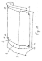
- FIG. 10 is a detail of the vehicle seat with the seat frame 3 and the support plate 4 shown, on which a gas bag 5 is attached.
- a gas bag 5 In order to prevent the gas bag 5 from being displaced in the deflated position, it is necessary to provide fastening means which fix the gas bag 5 on the support plate 4. These fasteners must be in addition to the attachment, which is provided by the gas generator, not shown.
- These fasteners In order to ensure the most flat and secure resting of the airbag 5 on the seat frame 3, in particular on the support plate 4 unfolded and lying in one plane, are in the first embodiment of the invention at the four corners of the airbag. 5 Fixing elements 11 provided in the form of hooks or spacers on straps or bands, which in openings 12th best in the FIG. 11 to recognize, intervene.
- the openings 12 are formed at the corners of the airbag and allow the attachment means 11, such as hooks or the like, can be inserted into the openings or recesses 12.
- the part of the gas bag 5 in which the openings 12 are formed are not formed in the area filled with gas by the gas generator 6. If these openings 12 are used as relief or vent openings, corresponding connection openings for the fluidic connection with the inner volume of the airbag 5 would have to be provided.
- the gas bag 5 is flat and unfolded on the support plate 4.
- the fasteners 11 or interlocking elements are solved, present by being pulled out of the openings 12 or unhooked.
- the interlocking elements 11 or hooks are parts of a thin holding element 13, in this case made of plastic, which rests flat on the surface of the support plate 4 and is fixed there, for example via an adhesive.
- the shape and size of the retaining element 13 may also be configured differently, it may also be attached to the support plate 4 or the seat frame 3 in other ways, for example via rivets, form-locking elements or screws. While the flat shape of the deflated airbag 5 is ensured by the fasteners 11, these impair not or only insignificantly the deployment of the airbag 5, so that the desired function of Antisubmarining is guaranteed.
- FIG. 12 a variant of the attachment of the non-inflated airbag 5 on the support plate 4 is shown.
- the attachment takes place via arranged inside the airbag 5 rigid, but elastic plastic or metal tongues 15, which in the partially cut Gas bag 5 are shown.
- the tongues or tabs 15 may be connected to each other and extend towards the corners of the airbag 5. If the tongues 15 are joined together to form a component, it may be attached to the gas generator or to the support plate 4 and due to the bias, will hold a similar Bending spring or dead center, the corners of the airbag 5 fixed to the support plate 4. As soon as gas is introduced into the gas bag 5 via the gas generator, this pulls together and bends the fixing elements or tongues 15 upwards, which in the FIG. 13 is shown in the right upper corner shown partially in section. Due to the flexible configuration of the tongues 15, these bend upwards and allow inflation and enlargement of the gas bag volume in order to lift or stiffen the support plate or the seat cushion.
Landscapes
- Engineering & Computer Science (AREA)
- Mechanical Engineering (AREA)
- Air Bags (AREA)
- Seats For Vehicles (AREA)
- Forklifts And Lifting Vehicles (AREA)
- Vehicle Waterproofing, Decoration, And Sanitation Devices (AREA)
Applications Claiming Priority (2)
| Application Number | Priority Date | Filing Date | Title |
|---|---|---|---|
| DE102006011105A DE102006011105B4 (de) | 2006-03-08 | 2006-03-08 | Sicherheitsanordnung in einem Fahrzeugsitz |
| PCT/EP2007/002014 WO2007101689A1 (de) | 2006-03-08 | 2007-03-08 | Sicherheitsanordnung in einem fahrzeugsitz |
Publications (2)
| Publication Number | Publication Date |
|---|---|
| EP1991448A1 EP1991448A1 (de) | 2008-11-19 |
| EP1991448B1 true EP1991448B1 (de) | 2011-03-16 |
Family
ID=38134284
Family Applications (1)
| Application Number | Title | Priority Date | Filing Date |
|---|---|---|---|
| EP07723109A Active EP1991448B1 (de) | 2006-03-08 | 2007-03-08 | Sicherheitsanordnung in einem fahrzeugsitz |
Country Status (6)
| Country | Link |
|---|---|
| US (1) | US7997611B2 (enExample) |
| EP (1) | EP1991448B1 (enExample) |
| JP (1) | JP4694632B2 (enExample) |
| AT (1) | ATE501900T1 (enExample) |
| DE (2) | DE102006011105B4 (enExample) |
| WO (1) | WO2007101689A1 (enExample) |
Families Citing this family (9)
| Publication number | Priority date | Publication date | Assignee | Title |
|---|---|---|---|---|
| DE102010014029B4 (de) | 2010-04-06 | 2014-06-26 | Autoliv Development Ab | Rückhaltesystem und Verfahren zur Ansteuerung eines Rückhaltesystems für Kraftfahrzeuge |
| US8523220B1 (en) | 2012-03-19 | 2013-09-03 | Amsafe, Inc. | Structure mounted airbag assemblies and associated systems and methods |
| US8702120B2 (en) | 2012-06-27 | 2014-04-22 | Ford Global Technologies, Llc | Active bolster deployed from vehicle seat |
| US8998248B2 (en) | 2013-03-15 | 2015-04-07 | Autoliv Asp, Inc. | Mounting arrangements for airbags |
| US9944245B2 (en) | 2015-03-28 | 2018-04-17 | Amsafe, Inc. | Extending pass-through airbag occupant restraint systems, and associated systems and methods |
| EP3283336B1 (en) | 2015-04-11 | 2019-11-20 | AmSafe, Inc. | Active airbag vent system |
| US10604259B2 (en) | 2016-01-20 | 2020-03-31 | Amsafe, Inc. | Occupant restraint systems having extending restraints, and associated systems and methods |
| US10899456B2 (en) * | 2017-10-06 | 2021-01-26 | Rockwell Collins, Inc. | Dynamically tilted seat pan |
| DE102021129401B4 (de) | 2021-11-11 | 2023-11-23 | Joyson Safety Systems Germany Gmbh | Rückhaltevorrichtung und Fahrzeugsitz mit Rückhaltevorrichtung |
Family Cites Families (22)
| Publication number | Priority date | Publication date | Assignee | Title |
|---|---|---|---|---|
| DE2913474A1 (de) * | 1979-04-04 | 1980-10-16 | Daimler Benz Ag | Sitz fuer kraftwagen |
| JP3321978B2 (ja) * | 1994-04-05 | 2002-09-09 | タカタ株式会社 | エアバッグ装置 |
| DE19813832C2 (de) * | 1998-03-20 | 2003-10-23 | Takata Petri Ag | Gassack für ein Airbagmodul |
| DE29815521U1 (de) * | 1998-08-31 | 1998-12-03 | Thau, Barbara, 58285 Gevelsberg | Sitz für ein Fahrzeug |
| JP2001247010A (ja) * | 1999-12-28 | 2001-09-11 | Takata Corp | 乗員保護装置 |
| JP4239387B2 (ja) * | 2000-09-06 | 2009-03-18 | 豊田合成株式会社 | 車両用シート |
| GB2385028A (en) | 2002-02-12 | 2003-08-13 | Autoliv Dev | An inflatable safety arrangement |
| JP3972736B2 (ja) * | 2002-06-04 | 2007-09-05 | タカタ株式会社 | 乗員保護装置 |
| US20060017266A1 (en) * | 2003-09-30 | 2006-01-26 | Takata Corporation | Passenger protecting device |
| JP4581812B2 (ja) * | 2003-09-30 | 2010-11-17 | タカタ株式会社 | 乗員保護装置 |
| JP4674468B2 (ja) * | 2004-02-10 | 2011-04-20 | タカタ株式会社 | 乗員保護装置 |
| JP2005231505A (ja) * | 2004-02-19 | 2005-09-02 | Takata Corp | 乗員保護装置 |
| GB2412092A (en) * | 2004-03-16 | 2005-09-21 | Autoliv Dev | Vehicle seat with anti-submarining air-bag on a support plate |
| JP2005306251A (ja) * | 2004-04-22 | 2005-11-04 | Autoliv Development Ab | インフレータバッグ及びそれを用いた車両用シートクッション装置 |
| JP4541225B2 (ja) * | 2005-05-09 | 2010-09-08 | トヨタ紡織株式会社 | 車両用シート |
| JP4715523B2 (ja) * | 2005-10-25 | 2011-07-06 | タカタ株式会社 | 乗員拘束装置 |
| JP2007118817A (ja) * | 2005-10-28 | 2007-05-17 | Takata Corp | 乗員拘束装置 |
| JP5078248B2 (ja) * | 2005-10-28 | 2012-11-21 | タカタ株式会社 | 乗員拘束装置 |
| JP4802659B2 (ja) * | 2005-10-28 | 2011-10-26 | タカタ株式会社 | 乗員拘束装置 |
| DE602006014787D1 (de) * | 2005-12-01 | 2010-07-22 | Toyoda Gosei Kk | Passagierschutzvorrichtung |
| US7648161B2 (en) * | 2006-04-19 | 2010-01-19 | Honda Motor Co., Ltd. | Airbag device |
| US20080088119A1 (en) * | 2006-10-13 | 2008-04-17 | Yoshiki Murakami | Passenger constraining apparatus |
-
2006
- 2006-03-08 DE DE102006011105A patent/DE102006011105B4/de not_active Expired - Fee Related
-
2007
- 2007-03-08 DE DE502007006724T patent/DE502007006724D1/de active Active
- 2007-03-08 US US12/224,522 patent/US7997611B2/en active Active
- 2007-03-08 AT AT07723109T patent/ATE501900T1/de active
- 2007-03-08 JP JP2008557668A patent/JP4694632B2/ja active Active
- 2007-03-08 WO PCT/EP2007/002014 patent/WO2007101689A1/de not_active Ceased
- 2007-03-08 EP EP07723109A patent/EP1991448B1/de active Active
Also Published As
| Publication number | Publication date |
|---|---|
| ATE501900T1 (de) | 2011-04-15 |
| JP4694632B2 (ja) | 2011-06-08 |
| DE102006011105B4 (de) | 2010-09-16 |
| DE102006011105A1 (de) | 2007-09-20 |
| WO2007101689A1 (de) | 2007-09-13 |
| US20090273166A1 (en) | 2009-11-05 |
| JP2009528945A (ja) | 2009-08-13 |
| EP1991448A1 (de) | 2008-11-19 |
| US7997611B2 (en) | 2011-08-16 |
| DE502007006724D1 (de) | 2011-04-28 |
Similar Documents
| Publication | Publication Date | Title |
|---|---|---|
| EP1991448B1 (de) | Sicherheitsanordnung in einem fahrzeugsitz | |
| DE102010060928B4 (de) | 3Airbagvorrichtung für ein Fahrzeug | |
| DE60019963T2 (de) | Fahrzeugsitz | |
| DE102005057439B4 (de) | Fahrzeugsitz-Anordnung | |
| DE102011051318B4 (de) | Interne airbag-vorrichtung | |
| EP1957325B1 (de) | Fahrzeuginsassen-rückhaltesysteme mit einem in einem fahrzeugsitz angeordneten aufblasbaren gassack | |
| DE10001658B4 (de) | Luftsackmodul | |
| DE10225676B4 (de) | Insassen-Rückhaltesystem | |
| DE112022002443T5 (de) | Sicherheitsgurt-airbag | |
| DE112008003873T5 (de) | Fahrzeugsitzanordnung | |
| DE102007052974A1 (de) | Rückhaltesystem für vordere Fahrzeuginsassen | |
| DE10225677A1 (de) | Insassen-Rückhaltesystem | |
| DE102018104392A1 (de) | Gassackmodul sowie Fahrzeuginsassen-Rückhaltesystem | |
| DE102018112859A1 (de) | An einer Stirnwand montierter Airbag für Vordersitze | |
| DE102009052752B4 (de) | Airbagvorrichtung für einen vorderen Beifahrersitz | |
| DE102010016998A1 (de) | Airbag-Vorrichtung für ein Fahrzeug | |
| WO2006128591A1 (de) | Airbaganordnung | |
| DE102013224418A1 (de) | Aktives Polster mit aktiver Lüftungsöffnung zur Belastungsverwaltung | |
| DE102012202471A1 (de) | Insassenschutzvorrichtung und Insassenschutzberfahren | |
| DE102014001952A1 (de) | Insassenschutzvorrichtung für ein Fahrzeug und Fahrzeug | |
| DE102009044692A1 (de) | Dach-Airbag-Vorrichtung für Fahrzeuge | |
| DE102016122065A1 (de) | Sitz mit entfaltbarem Kunststoffbalken | |
| DE102021104203A1 (de) | Insassenrückhaltesystem | |
| DE19750945C2 (de) | Seitenaufprallschutzmodul zur Montage an einem Sitz eines Kraftfahrzeugs | |
| DE102021000984A1 (de) | Fahrzeugsitzanordnung für ein Fahrzeug |
Legal Events
| Date | Code | Title | Description |
|---|---|---|---|
| PUAI | Public reference made under article 153(3) epc to a published international application that has entered the european phase |
Free format text: ORIGINAL CODE: 0009012 |
|
| 17P | Request for examination filed |
Effective date: 20080825 |
|
| AK | Designated contracting states |
Kind code of ref document: A1 Designated state(s): AT BE BG CH CY CZ DE DK EE ES FI FR GB GR HU IE IS IT LI LT LU LV MC MT NL PL PT RO SE SI SK TR |
|
| 17Q | First examination report despatched |
Effective date: 20100519 |
|
| GRAP | Despatch of communication of intention to grant a patent |
Free format text: ORIGINAL CODE: EPIDOSNIGR1 |
|
| GRAS | Grant fee paid |
Free format text: ORIGINAL CODE: EPIDOSNIGR3 |
|
| GRAA | (expected) grant |
Free format text: ORIGINAL CODE: 0009210 |
|
| AK | Designated contracting states |
Kind code of ref document: B1 Designated state(s): AT BE BG CH CY CZ DE DK EE ES FI FR GB GR HU IE IS IT LI LT LU LV MC MT NL PL PT RO SE SI SK TR |
|
| REG | Reference to a national code |
Ref country code: GB Ref legal event code: FG4D Free format text: NOT ENGLISH |
|
| REG | Reference to a national code |
Ref country code: CH Ref legal event code: EP |
|
| REG | Reference to a national code |
Ref country code: IE Ref legal event code: FG4D |
|
| REF | Corresponds to: |
Ref document number: 502007006724 Country of ref document: DE Date of ref document: 20110428 Kind code of ref document: P |
|
| REG | Reference to a national code |
Ref country code: DE Ref legal event code: R096 Ref document number: 502007006724 Country of ref document: DE Effective date: 20110428 |
|
| REG | Reference to a national code |
Ref country code: NL Ref legal event code: VDEP Effective date: 20110316 |
|
| PG25 | Lapsed in a contracting state [announced via postgrant information from national office to epo] |
Ref country code: LT Free format text: LAPSE BECAUSE OF FAILURE TO SUBMIT A TRANSLATION OF THE DESCRIPTION OR TO PAY THE FEE WITHIN THE PRESCRIBED TIME-LIMIT Effective date: 20110316 Ref country code: ES Free format text: LAPSE BECAUSE OF FAILURE TO SUBMIT A TRANSLATION OF THE DESCRIPTION OR TO PAY THE FEE WITHIN THE PRESCRIBED TIME-LIMIT Effective date: 20110627 Ref country code: SE Free format text: LAPSE BECAUSE OF FAILURE TO SUBMIT A TRANSLATION OF THE DESCRIPTION OR TO PAY THE FEE WITHIN THE PRESCRIBED TIME-LIMIT Effective date: 20110316 Ref country code: LV Free format text: LAPSE BECAUSE OF FAILURE TO SUBMIT A TRANSLATION OF THE DESCRIPTION OR TO PAY THE FEE WITHIN THE PRESCRIBED TIME-LIMIT Effective date: 20110316 Ref country code: GR Free format text: LAPSE BECAUSE OF FAILURE TO SUBMIT A TRANSLATION OF THE DESCRIPTION OR TO PAY THE FEE WITHIN THE PRESCRIBED TIME-LIMIT Effective date: 20110617 |
|
| LTIE | Lt: invalidation of european patent or patent extension |
Effective date: 20110316 |
|
| PG25 | Lapsed in a contracting state [announced via postgrant information from national office to epo] |
Ref country code: CY Free format text: LAPSE BECAUSE OF FAILURE TO SUBMIT A TRANSLATION OF THE DESCRIPTION OR TO PAY THE FEE WITHIN THE PRESCRIBED TIME-LIMIT Effective date: 20110316 Ref country code: BG Free format text: LAPSE BECAUSE OF FAILURE TO SUBMIT A TRANSLATION OF THE DESCRIPTION OR TO PAY THE FEE WITHIN THE PRESCRIBED TIME-LIMIT Effective date: 20110616 Ref country code: SI Free format text: LAPSE BECAUSE OF FAILURE TO SUBMIT A TRANSLATION OF THE DESCRIPTION OR TO PAY THE FEE WITHIN THE PRESCRIBED TIME-LIMIT Effective date: 20110316 Ref country code: FI Free format text: LAPSE BECAUSE OF FAILURE TO SUBMIT A TRANSLATION OF THE DESCRIPTION OR TO PAY THE FEE WITHIN THE PRESCRIBED TIME-LIMIT Effective date: 20110316 |
|
| REG | Reference to a national code |
Ref country code: IE Ref legal event code: FD4D |
|
| PG25 | Lapsed in a contracting state [announced via postgrant information from national office to epo] |
Ref country code: EE Free format text: LAPSE BECAUSE OF FAILURE TO SUBMIT A TRANSLATION OF THE DESCRIPTION OR TO PAY THE FEE WITHIN THE PRESCRIBED TIME-LIMIT Effective date: 20110316 Ref country code: IE Free format text: LAPSE BECAUSE OF FAILURE TO SUBMIT A TRANSLATION OF THE DESCRIPTION OR TO PAY THE FEE WITHIN THE PRESCRIBED TIME-LIMIT Effective date: 20110316 Ref country code: PT Free format text: LAPSE BECAUSE OF FAILURE TO SUBMIT A TRANSLATION OF THE DESCRIPTION OR TO PAY THE FEE WITHIN THE PRESCRIBED TIME-LIMIT Effective date: 20110718 |
|
| PG25 | Lapsed in a contracting state [announced via postgrant information from national office to epo] |
Ref country code: SK Free format text: LAPSE BECAUSE OF FAILURE TO SUBMIT A TRANSLATION OF THE DESCRIPTION OR TO PAY THE FEE WITHIN THE PRESCRIBED TIME-LIMIT Effective date: 20110316 Ref country code: IS Free format text: LAPSE BECAUSE OF FAILURE TO SUBMIT A TRANSLATION OF THE DESCRIPTION OR TO PAY THE FEE WITHIN THE PRESCRIBED TIME-LIMIT Effective date: 20110716 Ref country code: RO Free format text: LAPSE BECAUSE OF FAILURE TO SUBMIT A TRANSLATION OF THE DESCRIPTION OR TO PAY THE FEE WITHIN THE PRESCRIBED TIME-LIMIT Effective date: 20110316 Ref country code: CZ Free format text: LAPSE BECAUSE OF FAILURE TO SUBMIT A TRANSLATION OF THE DESCRIPTION OR TO PAY THE FEE WITHIN THE PRESCRIBED TIME-LIMIT Effective date: 20110316 |
|
| PG25 | Lapsed in a contracting state [announced via postgrant information from national office to epo] |
Ref country code: NL Free format text: LAPSE BECAUSE OF FAILURE TO SUBMIT A TRANSLATION OF THE DESCRIPTION OR TO PAY THE FEE WITHIN THE PRESCRIBED TIME-LIMIT Effective date: 20110316 |
|
| PLBE | No opposition filed within time limit |
Free format text: ORIGINAL CODE: 0009261 |
|
| STAA | Information on the status of an ep patent application or granted ep patent |
Free format text: STATUS: NO OPPOSITION FILED WITHIN TIME LIMIT |
|
| 26N | No opposition filed |
Effective date: 20111219 |
|
| PG25 | Lapsed in a contracting state [announced via postgrant information from national office to epo] |
Ref country code: IT Free format text: LAPSE BECAUSE OF FAILURE TO SUBMIT A TRANSLATION OF THE DESCRIPTION OR TO PAY THE FEE WITHIN THE PRESCRIBED TIME-LIMIT Effective date: 20110316 Ref country code: DK Free format text: LAPSE BECAUSE OF FAILURE TO SUBMIT A TRANSLATION OF THE DESCRIPTION OR TO PAY THE FEE WITHIN THE PRESCRIBED TIME-LIMIT Effective date: 20110316 Ref country code: PL Free format text: LAPSE BECAUSE OF FAILURE TO SUBMIT A TRANSLATION OF THE DESCRIPTION OR TO PAY THE FEE WITHIN THE PRESCRIBED TIME-LIMIT Effective date: 20110316 |
|
| REG | Reference to a national code |
Ref country code: DE Ref legal event code: R097 Ref document number: 502007006724 Country of ref document: DE Effective date: 20111219 |
|
| PGFP | Annual fee paid to national office [announced via postgrant information from national office to epo] |
Ref country code: DE Payment date: 20120111 Year of fee payment: 6 |
|
| BERE | Be: lapsed |
Owner name: AUTOLIV DEVELOPMENT A.B. Effective date: 20120331 |
|
| PG25 | Lapsed in a contracting state [announced via postgrant information from national office to epo] |
Ref country code: MC Free format text: LAPSE BECAUSE OF NON-PAYMENT OF DUE FEES Effective date: 20120331 |
|
| REG | Reference to a national code |
Ref country code: CH Ref legal event code: PL |
|
| GBPC | Gb: european patent ceased through non-payment of renewal fee |
Effective date: 20120308 |
|
| PG25 | Lapsed in a contracting state [announced via postgrant information from national office to epo] |
Ref country code: BE Free format text: LAPSE BECAUSE OF NON-PAYMENT OF DUE FEES Effective date: 20120331 Ref country code: LI Free format text: LAPSE BECAUSE OF NON-PAYMENT OF DUE FEES Effective date: 20120331 Ref country code: CH Free format text: LAPSE BECAUSE OF NON-PAYMENT OF DUE FEES Effective date: 20120331 Ref country code: GB Free format text: LAPSE BECAUSE OF NON-PAYMENT OF DUE FEES Effective date: 20120308 |
|
| REG | Reference to a national code |
Ref country code: AT Ref legal event code: MM01 Ref document number: 501900 Country of ref document: AT Kind code of ref document: T Effective date: 20120308 |
|
| PG25 | Lapsed in a contracting state [announced via postgrant information from national office to epo] |
Ref country code: MT Free format text: LAPSE BECAUSE OF FAILURE TO SUBMIT A TRANSLATION OF THE DESCRIPTION OR TO PAY THE FEE WITHIN THE PRESCRIBED TIME-LIMIT Effective date: 20110316 Ref country code: AT Free format text: LAPSE BECAUSE OF NON-PAYMENT OF DUE FEES Effective date: 20120308 |
|
| REG | Reference to a national code |
Ref country code: DE Ref legal event code: R119 Ref document number: 502007006724 Country of ref document: DE Effective date: 20131001 |
|
| PG25 | Lapsed in a contracting state [announced via postgrant information from national office to epo] |
Ref country code: DE Free format text: LAPSE BECAUSE OF NON-PAYMENT OF DUE FEES Effective date: 20131001 |
|
| PG25 | Lapsed in a contracting state [announced via postgrant information from national office to epo] |
Ref country code: TR Free format text: LAPSE BECAUSE OF FAILURE TO SUBMIT A TRANSLATION OF THE DESCRIPTION OR TO PAY THE FEE WITHIN THE PRESCRIBED TIME-LIMIT Effective date: 20110316 |
|
| PG25 | Lapsed in a contracting state [announced via postgrant information from national office to epo] |
Ref country code: LU Free format text: LAPSE BECAUSE OF NON-PAYMENT OF DUE FEES Effective date: 20120308 |
|
| PG25 | Lapsed in a contracting state [announced via postgrant information from national office to epo] |
Ref country code: HU Free format text: LAPSE BECAUSE OF FAILURE TO SUBMIT A TRANSLATION OF THE DESCRIPTION OR TO PAY THE FEE WITHIN THE PRESCRIBED TIME-LIMIT Effective date: 20070308 |
|
| REG | Reference to a national code |
Ref country code: FR Ref legal event code: PLFP Year of fee payment: 10 |
|
| REG | Reference to a national code |
Ref country code: FR Ref legal event code: PLFP Year of fee payment: 11 |
|
| REG | Reference to a national code |
Ref country code: FR Ref legal event code: PLFP Year of fee payment: 12 |
|
| PGFP | Annual fee paid to national office [announced via postgrant information from national office to epo] |
Ref country code: FR Payment date: 20250324 Year of fee payment: 19 |