EP1991436B1 - Dispositif de reglage pour un couvercle de toit ouvrant d'un vehicule - Google Patents
Dispositif de reglage pour un couvercle de toit ouvrant d'un vehicule Download PDFInfo
- Publication number
- EP1991436B1 EP1991436B1 EP07721967A EP07721967A EP1991436B1 EP 1991436 B1 EP1991436 B1 EP 1991436B1 EP 07721967 A EP07721967 A EP 07721967A EP 07721967 A EP07721967 A EP 07721967A EP 1991436 B1 EP1991436 B1 EP 1991436B1
- Authority
- EP
- European Patent Office
- Prior art keywords
- slider
- guide rail
- locking
- adjustment device
- rotary latch
- Prior art date
- Legal status (The legal status is an assumption and is not a legal conclusion. Google has not performed a legal analysis and makes no representation as to the accuracy of the status listed.)
- Not-in-force
Links
Images


Classifications
-
- B—PERFORMING OPERATIONS; TRANSPORTING
- B60—VEHICLES IN GENERAL
- B60J—WINDOWS, WINDSCREENS, NON-FIXED ROOFS, DOORS, OR SIMILAR DEVICES FOR VEHICLES; REMOVABLE EXTERNAL PROTECTIVE COVERINGS SPECIALLY ADAPTED FOR VEHICLES
- B60J7/00—Non-fixed roofs; Roofs with movable panels, e.g. rotary sunroofs
- B60J7/185—Locking arrangements
- B60J7/19—Locking arrangements for rigid panels
- B60J7/192—Locking arrangements for rigid panels for locking the sunroof panel to the roof
-
- B—PERFORMING OPERATIONS; TRANSPORTING
- B60—VEHICLES IN GENERAL
- B60J—WINDOWS, WINDSCREENS, NON-FIXED ROOFS, DOORS, OR SIMILAR DEVICES FOR VEHICLES; REMOVABLE EXTERNAL PROTECTIVE COVERINGS SPECIALLY ADAPTED FOR VEHICLES
- B60J7/00—Non-fixed roofs; Roofs with movable panels, e.g. rotary sunroofs
- B60J7/02—Non-fixed roofs; Roofs with movable panels, e.g. rotary sunroofs of sliding type, e.g. comprising guide shoes
- B60J7/04—Non-fixed roofs; Roofs with movable panels, e.g. rotary sunroofs of sliding type, e.g. comprising guide shoes with rigid plate-like element or elements, e.g. open roofs with harmonica-type folding rigid panels
- B60J7/05—Non-fixed roofs; Roofs with movable panels, e.g. rotary sunroofs of sliding type, e.g. comprising guide shoes with rigid plate-like element or elements, e.g. open roofs with harmonica-type folding rigid panels pivoting upwardly to vent mode and moving downward before sliding to fully open mode
Definitions
- the present invention relates to an adjustment device for a sliding roof cover on a vehicle according to the preamble of claim 1.
- Such adjusting device is for example from the DE 100 09 387 C1 known.
- the sunroof lid can be issued outwardly from a closed position about a front pivot axis to the outside and then moved to the rear to release a roof opening.
- a lid holder is arranged in each case, which is coupled with two arranged in the vehicle longitudinal direction one behind the other, the movement of the lid controlling sliders, which are guided in a running in the vehicle longitudinal direction vehicle-fixed guide rail.
- a first of the two sliders is movable as a drivable slide along the guide rail and takes over a part of its range of motion formed by a slide pin and a control lever second slider, whereas the first slider over another part of its range of motion, the second slider in a predetermined position along leaves the guide rail.
- the control lever of the second slider is controlled by a linkage coupling between the two sliders pivoted so that a locking pin arranged on the control lever is brought when leaving the second slider by a height adjustment in a guide rail recess to lock the second slider to the guide rail.
- the locking of the second slider is ensured by maintaining the linkage coupling over the corresponding part of the range of motion of the first slider.
- This method of locking the detent has the disadvantage that when leaving the second slider a link coupling between the two sliders must be maintained, which in particular means an increased design effort if after locking the second slider a comparatively large adjustment of the first slider is desired. Regardless, this type of locking the lock with unfavorable Connected to power moments that can adversely affect, for example, the ease of sliding movement.
- Similar adjusting devices are for example from the DE 37 15 268 A1 and the DE 100 39 150 C1 known.
- one of two running in a guide rail sliders is locked controlled by the other slider, including a locking member is pivoted into a guide rail recess and is pivoted out again for unlocking.
- the locking element is biased by a spring in the locking direction, biased in the second-mentioned publication by a spring in unlocking.
- the known mechanisms for locking and releasing the respective slider or for securing (locking) and unlocking (unlocking) the detent must absorb unfavorable forces or transmit forces in a manner to other components of the adjustment, which may adversely affect the slider movements.
- a controlled by the first slider is rotatable about a vertical axis rotary latch arranged on the second slider, which is rotated when leaving the second slider, after the height adjustment of the locking element in a lock locking the rotary position.
- the reliability of the solution according to the invention is based on the fact that a z. B. caused by vibration or shock force of the locking element in the vertical direction by the rotary latch safely (to avoid movement of the locking element) can be added and beyond the rotary latch loaded at best parallel to its axis of rotation, but not a rotating moment of force exerted on the rotary latch.
- the rotary latch can readily be actuated (pivotable) in the direction of locking rotation and / or unlocking direction without appreciable application of force (eg by frictional forces).
- a preferred application of the invention is the adjustment of a sunroof cover, which closes a roof opening in a closed position, can be swung up into an open position ("ventilation position") and can then be pushed back.
- This is z.
- the adjustment is equally z. B. suitable for sunroofs, in which the lid lowered starting from the closed position alternatively or in addition to Hochschwenkung and then be pushed back.
- first slider two along a guide rail movable slider for controlling the (in any designable) sliding roof cover movement are provided and a driving coupling between the sliders only over part of the range of motion of the two sliders ("first slider ”) consists.
- the longitudinal direction in which the vehicle-fixed guide rail extends is the "sliding direction" of the sliding roof cover. Usually, this longitudinal direction is identical to the longitudinal direction of the vehicle in question.
- At least one of the two sliders can be connected at least indirectly to the sliding roof cover or to a cover carrier carrying the cover.
- the lid or lid carrier may, for. B. by Ausstellhebel, Hubkulissen etc. be connected to the gliders.
- the first slider along the guide rail moving drive device can in a conventional manner z. B. include a driving connection to the first slider standing, pressure-rigid drive cable, which is guided on or in the guide rail extending in the longitudinal direction.
- the rotary latch on a radially projecting locking cam which pivots for locking in a space created by the height adjustment clearance between a connected to the locking member portion of the second slider and a portion of the guide rail.
- this free space or the locking cam pivoting into it is preferably dimensioned so that the pivoting takes place substantially without appreciable application of force (for example due to frictional forces). The same applies to the swinging out of the locking cam from the free space in the case of unlocking the lock.
- the locking cam is preferably bounded in the axial direction (vertical direction) by two locking cam surfaces extending substantially orthogonally to the axial direction, against which the relevant section of the second slider and on the other hand the relevant section of the guide rail (preferably likewise with horizontal stop surfaces) abut in the locked state.
- the rotary latch two radially projecting, mutually angularly offset Control cam having a laterally projecting control pin of the first slider cooperates to rotate the rotary latch.
- the two control cams are arranged at the same height on the rotary latch. If in this case the above-mentioned locking cam is provided, then this is preferably arranged axially offset from the two control cams on the rotary latch.
- the rotary latch is produced as a plastic molded part (eg injection molded part). This is unproblematic insofar as this component does not have to be significantly stressed during its actuation (rotation) and the "locking force" merely loads the rotary latch on axial pressure.
- control pin of the first slider may have other functions in addition to the operation of the rotary latch in the adjusting device according to the invention.
- control bolt of the first slider interacts with a slide track of a portion of the second slider connected to the locking element in order to effect the height adjustment. If a stop for the control pin is provided on at least one end of such a slide track, so the control bolt can also cause by means of this stop the driving coupling between the two sliders.
- the rotary latch is secured in its locking rotational position and / or its unlocking rotational position by a spring load. It is worth noting in this context that such a spring load, in contrast to the spring loads mentioned at the outset with reference to the prior art may advantageously be extremely small, since all forces acting on these in operation in terms of rotation of the rotary latch can be provided very small ,
- the first slider is completely decoupled from the second slider after leaving the second slider. If the first slider z. B. coupled via a link coupling with the second slider, so the complete Entkoppeliana be provided that the relevant slide track is "open" at one end, so that at this point decoupling can be done and the first slider left behind second slider in principle, can be moved arbitrarily far.
- the first slider with a laterally projecting control bolt runs in a slide track (eg slide slot) open on one side, which is provided on the second slider, in particular on a section of the second slider, with the height-adjustable locking element connected is.
- the locking element is arranged on a pivotable about a transverse axis locking lever of the second slider.
- the height adjustment of the locking element can then be effected by pivoting the locking lever, wherein the arrangement of the locking element in the region of the free end of the locking lever is preferred for a large height adjustment at a predetermined pivoting angle.
- the locking element protrudes laterally from the second slider and during the entrainment of the second slider in a limited by a horizontal guide rail web guide channel of the guide rail and penetrates upon reaching the predetermined position by the height adjustment in a recess of the guide rail web.
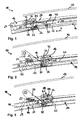
- Fig. 1 shows a front portion of a generally designated 10 adjusting device for a sunroof cover 12 on a motor vehicle.
- the sliding direction of the lid 12, at the same time vehicle longitudinal direction, is indicated in the figure by an arrow x.
- the adjusting device 10 comprises (on each cover side) a vehicle-fixed guide rail 14 running in the longitudinal direction x for guiding a (front) first slider 16 and a (rear) second slider 18.
- the sliders 16, 18 serve to control all movements of the sliding roof cover 12, which in the in Fig. 1 illustrated situation closes a roof opening (roof opening) of the motor vehicle roof, not shown. In this closed position, the cover 12 is arranged approximately flush with the (not shown) vehicle roof contour.
- the lid 12 can first be raised (ventilation position) and then backwards (in Fig. 1 to the right) are moved over a fixed roof skin section.
- the cover 12 is connected on both sides in each case via two deployment levers which are each articulated on the vehicle side in the region of the guide rail 14.
- the front of these two release levers is in Fig. 1 to recognize and denoted by 20.
- a second, further back (in Fig. 1 further right) arranged release lever is in the in Fig. 1 not shown area.
- the first slider 16 is designed as a sliding carriage, which can be moved along the guide rail 14 in the direction x in a manner known per se by a pressure-resistant drive cable running in a channel of the guide rail 14.
- This state is considered a first intermediate position in Fig. 2 shown.
- the issue of the deployment lever 20 as a result of the movement of the first slider 16 is accomplished by running three laterally protruding from the release lever 20 sliders in three different guideways.
- a front slider 22 of the lever 20 runs in a slot 24 of the first slider 16
- a middle slider 26 of the lever 20 runs in a slide 28 of the guide rail 14
- a rear slider 30 of the lever 20 runs in a guide channel 32 of the guide rail fourteenth
- Fig. 3 shows a second intermediate position of the movement of the slider 16 to the rear.
- the entrainment coupling required for this purpose is accomplished by the engagement of a laterally projecting on the first slider 16 control pin 34 in a sloping portion of a control link 36 which is formed on the second slider 18.
- the control pin 34 presses the link 36 and thus the second slider 18 in synchronism with the movement of the first slider 16 to the rear.
- the control pin 34 in this case can not be moved relative to the guide slot 36 (obliquely downwards), since the gate area 36 of the second slider 18 is fixed in this movement phase in its height with respect to the guide rail 14.
- This determination is realized by a in the figures designated 38 locking contour (locking element) which projects laterally from the second slider 18 and in the guide channel 32 of the guide rail 14 runs.
- the guide channel 32 is bounded at the top by a guide rail web 40 (one of a plurality of such webs of the guide rail). Only when the coupled to take along sliders 16, 18, the in Fig. 3 have reached the position shown, the control pin 34 can move in the control link 36, since in this position, the locking contour 38 engages in a recess 42 of the guide rail 14 upwards.
- the in the Fig. 1 to 3 apparent part of the second slider 18 is formed as a pivotable "locking lever" (with the locking contour 38 at its free end), wherein the pivot axis is not shown in the figures and approximately at the right edge of Fig. 1 runs in the transverse direction. A corresponding pivot bearing of the second slider 18 is displaceably guided in the direction x by the guide rail 14.
- the locking mechanism is essentially formed by a rotary bolt 44 mounted on the second slider 18 and rotatable about a vertical axis. It is essential here that the rotary latch 44 when leaving the second slider 18, after the height adjustment of the illustrated portion of the second slider 18, is rotated in a locking position locking the locking. This rotation is realized in the illustrated embodiment by an action of the control pin 34 on one of two radially projecting from the rotary latch 44 control cam 46, 48.
- Fig. 4 is a perspective view (from the inside) in which it is clear how the control pin 34 of the driven slider 16 engages in the control link 36 of the second slider 18.
- Fig. 4 illustrated situation corresponds to in Fig. 3 illustrated situation (second intermediate position).
- FIGS. 5 and 6 show in perspective or in a section a third intermediate position in the movement sequence, in which the control bolt 34 starts against the first control cam 46.
- Fig. 5 only the control pin 34 is drawn from the first slider 16.
- the rotary latch 44 further comprises a radially projecting locking cam 50 which is provided in the axial direction offset to the control cam assembly 44, 46 and viewed in the circumferential direction approximately in the angular position of the second control cam 48.
- Fig. 9 the locking cam 50 is viewed in a region in the height direction between a surface 52 of the guide rail 14 and a control link 36 delimiting portion of the second slider 18, so that in Fig. 9 apparent, controlled by the control pin 34 height adjustment of the second slider 18 is also still ensured if in the further movement of the control pin 34, the control link 36 leaves (in Fig. 9 to the left).
- the pivoted locking cam 50 thus a simple and reliable locking of the second slider 18 is realized in the locked state.
- the 10 and 11 illustrate again in a cross-sectional view the unlocked state ( Fig. 10 ) or the locked state ( Fig. 11 ). It can be seen that the locking cam 50 is pivoted for locking in an axial clearance between the guide rail 14 and the second slider 18, the only by the previous height adjustment of the second slider 18 (in 10 and 11 to the top).
- Fig. 12 shows again in an exploded view some of the device components already described above.
- a leaf spring 54 is shown, which secures a latching connection of the rotary latch 44 on a snap-action receptacle 56 of the second slider 18 in the assembled state and on the other secures the rotary latch 44 both in its locking rotational position and its unlocking rotational position.
- the latter rotation lock is not required per se, but ensures particularly reliable that the rotary latch 44 reliably passes after actuation by the control pin 34 in one of its two Endburnwolfen and remains.
- This action of the spring 54 on the rotary latch 44 is achieved by two flats suitably arranged in the circumferential direction on the rotary bolt shaft, against which the spring 54 rests in the mounted state (cf. Fig. 6 and 8th ).
- a modification of the just described securing the rotational position of the rotary latch 44 According to this modification, a second slider 18 'is provided with a locking contour 38' and a snap-action receptacle 56 'for receiving a rotary latch of the type already described. Unlike the in Fig. 12 However, a fork-like trained projection 54 'of the second slider 18' formed in this area of plastic is additionally provided, the two “forks" rest elastically against corresponding flats on the shaft of the assembled rotary latch and thus assume the function of securing the rotational position.
Landscapes
- Engineering & Computer Science (AREA)
- Mechanical Engineering (AREA)
- Fittings On The Vehicle Exterior For Carrying Loads, And Devices For Holding Or Mounting Articles (AREA)
- Lock And Its Accessories (AREA)
Claims (8)
- Dispositif de réglage pour un couvercle de toit ouvrant (12) d'un véhicule, comprenant un rail de guidage (14) fixé au véhicule, s'étendant dans la direction longitudinale (x), pour le guidage de premier et deuxième coulisseaux (16, 18) commandant le déplacement du couvercle de toit ouvrant (12), disposés l'un derrière l'autre dans la direction longitudinale (x),
le premier coulisseau (16) pouvant être déplacé au moyen d'un dispositif d'entraînement le long du rail de guidage (14) et entraînant avec lui le deuxième coulisseau (18) sur une partie de sa plage de déplacement, et laissant en arrière le deuxième coulisseau (18) dans une position prédéfinie le long du rail de guidage (14) sur une autre partie de sa plage de déplacement,
un élément de blocage (38) réglable en hauteur et commandé par le premier coulisseau (16) étant disposé sur le deuxième coulisseau (18), et étant amené par un réglage en hauteur en connexion par engagement géométrique avec une portion de rail de guidage (42) lorsque le deuxième coulisseau (18) est laissé en arrière, afin de bloquer le deuxième coulisseau (18) sur le rail de guidage (14),
caractérisé en ce qu'un verrou rotatif (44) pouvant tourner autour d'un axe vertical et commandé par le premier coulisseau (16) est en outre disposé sur le deuxième coulisseau (18), lequel est tourné dans une position de rotation verrouillant le blocage lorsque le deuxième coulisseau (18) est laissé en arrière, après le réglage en hauteur de l'élément de blocage (38). - Dispositif de réglage selon la revendication 1, dans lequel le verrou rotatif (44) présente une came de verrouillage (50) saillant radialement, qui, pour le verrouillage dans un espace libre créé par le réglage en hauteur, pivote entre une portion du deuxième coulisseau (18) connectée à l'élément de blocage (38) et une portion (52) du rail de guidage (14).
- Dispositif de réglage selon l'une quelconque des revendications précédentes, dans lequel le verrou rotatif (44) présente deux cames de commande (46, 48) décalées angulairement l'une par rapport à l'autre et saillant radialement, avec lesquelles coopère un boulon de commande (34), saillant latéralement, du premier coulisseau (16) pour faire tourner le verrou rotatif (44).
- Dispositif de réglage selon la revendication 3, dans lequel le boulon de commande (34) du premier coulisseau (16) coopère avec une coulisse (36) d'une portion du deuxième coulisseau (18) connectée à l'élément de blocage (38), afin de provoquer le réglage en hauteur.
- Dispositif de réglage selon l'une quelconque des revendications précédentes, dans lequel le verrou rotatif (44) est fixé dans sa position rotative de verrouillage et/ou dans sa position rotative de déverrouillage par une sollicitation par ressort (54, 54').
- Dispositif de réglage selon l'une quelconque des revendications précédentes, dans lequel le premier coulisseau (16) est complètement désaccouplé du deuxième coulisseau (16) après que le deuxième coulisseau (18) a été laissé en arrière.
- Dispositif de réglage selon l'une quelconque des revendications précédentes, dans lequel l'élément de blocage (38) est disposé sur un levier de blocage du deuxième coulisseau (18) qui peut pivoter autour d'un axe transversal.
- Dispositif de réglage selon l'une quelconque des revendications précédentes, dans lequel l'élément de blocage (38) fait saillie latéralement depuis le deuxième coulisseau (18) et, pendant l'entraînement du deuxième coulisseau (18), passe dans un canal de guidage du rail de guidage limité par une nervure de rail de guidage horizontale (40), et une fois que la position prédéterminée a été atteinte par le réglage en hauteur pénètre dans un évidement (42) de la nervure du rail de guidage (40).
Applications Claiming Priority (2)
| Application Number | Priority Date | Filing Date | Title |
|---|---|---|---|
| DE102006010755A DE102006010755B4 (de) | 2006-03-08 | 2006-03-08 | Verstellvorrichtung für einen Schiebedachdeckel an einem Fahrzeug |
| PCT/DE2007/000366 WO2007101425A1 (fr) | 2006-03-08 | 2007-02-27 | Dispositif de reglage pour un couvercle de toit ouvrant d'un vehicule |
Publications (2)
| Publication Number | Publication Date |
|---|---|
| EP1991436A1 EP1991436A1 (fr) | 2008-11-19 |
| EP1991436B1 true EP1991436B1 (fr) | 2010-06-23 |
Family
ID=38132538
Family Applications (1)
| Application Number | Title | Priority Date | Filing Date |
|---|---|---|---|
| EP07721967A Not-in-force EP1991436B1 (fr) | 2006-03-08 | 2007-02-27 | Dispositif de reglage pour un couvercle de toit ouvrant d'un vehicule |
Country Status (6)
| Country | Link |
|---|---|
| US (1) | US20090079234A1 (fr) |
| EP (1) | EP1991436B1 (fr) |
| JP (1) | JP4836012B2 (fr) |
| CN (1) | CN101400532B (fr) |
| DE (2) | DE102006010755B4 (fr) |
| WO (1) | WO2007101425A1 (fr) |
Families Citing this family (13)
| Publication number | Priority date | Publication date | Assignee | Title |
|---|---|---|---|---|
| DE102011102890A1 (de) * | 2011-05-31 | 2012-12-06 | GM Global Technology Operations LLC (n. d. Gesetzen des Staates Delaware) | Beschattungssystem, Kraftfahrzeug und Verfahren hierzu |
| DE102012016504C5 (de) | 2012-08-20 | 2018-01-04 | Roof Systems Germany Gmbh | Schiebedachsystem |
| DE102013005217B4 (de) * | 2013-03-27 | 2019-03-14 | Webasto SE | Fahrzeug-Schiebedachvorrichtung mit zwei verstellbaren Deckeln |
| DE102014110626A1 (de) * | 2014-05-14 | 2015-11-19 | Webasto SE | Anordnung mit einem Deckel für ein Fahrzeugdach |
| DE102016203131A1 (de) * | 2016-02-26 | 2017-08-31 | Bos Gmbh & Co. Kg | Antriebssystem für einen beweglichen Dachteil eines Dachmoduls eines Kraftfahrzeugs |
| US10189339B2 (en) | 2016-07-27 | 2019-01-29 | Rugged Liner, Inc. | Tonneau cover system for a cargo bed of a vehicle |
| US9821643B1 (en) * | 2016-10-26 | 2017-11-21 | AISIN Technical Center of America, Inc. | Guide block for sunroof of an automobile |
| CN109803854B (zh) * | 2016-10-28 | 2021-12-03 | 拉格德莱诺公司 | 用于车辆的货厢的后箱盖系统 |
| DE102017202127A1 (de) | 2017-02-10 | 2018-08-16 | Bos Gmbh & Co. Kg | Schiebedachsystem für ein Kraftfahrzeug |
| CN107953760B (zh) * | 2017-11-23 | 2019-07-05 | 杭州科技职业技术学院 | 一种汽车天窗装置 |
| DE102018104610A1 (de) * | 2018-02-28 | 2019-08-29 | Webasto SE | Anordnung für ein Fahrzeugdach, Fahrzeugdach für ein Kraftfahrzeug und Kraftfahrzeug |
| US10960741B2 (en) | 2019-03-18 | 2021-03-30 | AISIN Technical Center of America, Inc. | Rotating lock having notch for sunroof check systems |
| DE102019113142A1 (de) * | 2019-05-17 | 2020-11-19 | Webasto SE | Anordnung und Verfahren zum Bewegen eines Deckels |
Family Cites Families (11)
| Publication number | Priority date | Publication date | Assignee | Title |
|---|---|---|---|---|
| FR2601303B1 (fr) * | 1986-07-12 | 1992-02-14 | Webasto Werk Baier Kg W | Dispositif de manoeuvre pour un toit ouvrant de vehicule dont le levier d'actionnement est relie avec le premier element de glissement. |
| DE3715268A1 (de) * | 1986-07-12 | 1988-01-21 | Webasto Werk Baier Kg W | Betaetigungsvorrichtung fuer ein fahrzeugdach |
| DE4320106C2 (de) * | 1993-06-17 | 1997-08-14 | Hs Products Ag Systemtechnik U | Vorrichtung zur Steuerung der Bewegung eines Fahrzeugschiebedachdeckels |
| DE19944853C5 (de) * | 1999-09-18 | 2007-02-22 | Magna Car Top Systems Gmbh | Antriebseinrichtung für in vorgegebener Abfolge gegeneinander verstellbare Teile, insbesondere Dach- und/oder Deckelteile von Kraftfahrzeugen |
| DE10009387C5 (de) * | 2000-02-29 | 2007-08-02 | Webasto S.P.A., Venaria | Vorrichtung zum Steuern der Bewegung eines Fahrzeugschiebedachdeckels |
| JP4389362B2 (ja) * | 2000-06-28 | 2009-12-24 | 株式会社豊田自動織機 | 車両用ティルト式サンルーフ |
| DE10039150C1 (de) * | 2000-08-05 | 2002-01-10 | Webasto Vehicle Sys Int Gmbh | Koppelvorrichtung |
| DE10063055B4 (de) * | 2000-12-18 | 2005-04-07 | Webasto Ag | Fahrzeugdach mit zwei verstellbaren Deckeln |
| DE10217147C1 (de) * | 2002-04-17 | 2003-10-16 | Webasto Vehicle Sys Int Gmbh | Windabweiser für öffnungsfähige Fahrzeugdächer |
| FR2842764B1 (fr) * | 2002-07-26 | 2006-02-03 | Webasto Systemes Carrosserie | Dispositif de configuration de pavillon de vehicule automobile, comprenant un rideau et un panneau coulissant mus par un meme moteur |
| DE102004027728B4 (de) * | 2004-02-20 | 2014-02-06 | Michael Heidan | Rast-Koppel-Mechanismus für ein Schiebedach |
-
2006
- 2006-03-08 DE DE102006010755A patent/DE102006010755B4/de not_active Expired - Fee Related
-
2007
- 2007-02-27 US US12/162,387 patent/US20090079234A1/en not_active Abandoned
- 2007-02-27 JP JP2008557585A patent/JP4836012B2/ja not_active Expired - Fee Related
- 2007-02-27 WO PCT/DE2007/000366 patent/WO2007101425A1/fr active Application Filing
- 2007-02-27 EP EP07721967A patent/EP1991436B1/fr not_active Not-in-force
- 2007-02-27 CN CN2007800082476A patent/CN101400532B/zh active Active
- 2007-02-27 DE DE502007004189T patent/DE502007004189D1/de active Active
Also Published As
| Publication number | Publication date |
|---|---|
| EP1991436A1 (fr) | 2008-11-19 |
| CN101400532B (zh) | 2010-08-04 |
| JP4836012B2 (ja) | 2011-12-14 |
| WO2007101425A1 (fr) | 2007-09-13 |
| DE502007004189D1 (de) | 2010-08-05 |
| JP2009528942A (ja) | 2009-08-13 |
| DE102006010755B4 (de) | 2008-02-28 |
| US20090079234A1 (en) | 2009-03-26 |
| DE102006010755A1 (de) | 2007-09-13 |
| CN101400532A (zh) | 2009-04-01 |
Similar Documents
| Publication | Publication Date | Title |
|---|---|---|
| EP1991436B1 (fr) | Dispositif de reglage pour un couvercle de toit ouvrant d'un vehicule | |
| EP1561620B1 (fr) | Mécanisme pour un toit glissant | |
| DE69413356T2 (de) | Antrieb für die Verschiebung eines Deckels bezüglich eines Fahrzeugdaches | |
| DE3715268C2 (fr) | ||
| EP1767388A2 (fr) | Porte pivotante-coulissante pour véhicules de transport de personnes | |
| EP1809503B1 (fr) | Systeme de toit coulissant pour vehicules automobiles | |
| EP1922220B1 (fr) | Toit pour vehicule comprenant au moins deux elements de recouvrement | |
| EP1072456B1 (fr) | Dispositif de tension de fermeture pour fixer de façon amovible un toit de véhicule à une partie de carrosserie d'un véhicule | |
| DE10057872B4 (de) | Hardtop-Fahrzeugdach | |
| EP2096027B1 (fr) | Commande de clapets | |
| DE102018130016A1 (de) | Schiebedachsystem für ein Kraftfahrzeug | |
| DE69602894T2 (de) | Schiebehebedach und ein mit einem solchen Schiebehebedach ausgerüstetes Kraftfahrzeug | |
| EP1791709A1 (fr) | Vehicule cabriolet | |
| DE102010018867A1 (de) | Fahrzeugdach und Verfahren zum Öffnen und Schließen eines Fahrzeugdachs | |
| DE602004006486T2 (de) | Verriegelungsmechanismus und ein damit ausgerüstetes Schiebedach | |
| EP2143859A2 (fr) | Système de verouillage | |
| EP1389662A2 (fr) | Dispositif d'ouverture et de fermeture d'un vantail dans un dormant | |
| DE102007024570B4 (de) | Scharnier für eine Kraftfahrzeugtür | |
| EP1798085B1 (fr) | Système de toit de véhicule pour un cabriolet | |
| EP1681194B1 (fr) | Toit ouvrant pour véhicule avec une gouttière amovible | |
| DE19714106C2 (de) | Umwandelbares Fahrzeugdach | |
| EP3675691B1 (fr) | Dispositif d'insertion permettant d'insérer une partie mobile d'un meuble ou d'un appareil ménager dans une position finale | |
| DE102018130013A1 (de) | Schiebedachsystem für ein Kraftfahrzeug | |
| DE10137949C2 (de) | Führungsanordnung für ein öffnungsfähiges Fahrzeugdach | |
| EP2572912B1 (fr) | Cinématique de fermeture pour toit pliant ouvrant |
Legal Events
| Date | Code | Title | Description |
|---|---|---|---|
| PUAI | Public reference made under article 153(3) epc to a published international application that has entered the european phase |
Free format text: ORIGINAL CODE: 0009012 |
|
| 17P | Request for examination filed |
Effective date: 20080828 |
|
| AK | Designated contracting states |
Kind code of ref document: A1 Designated state(s): DE FR GB NL |
|
| DAX | Request for extension of the european patent (deleted) | ||
| RBV | Designated contracting states (corrected) |
Designated state(s): DE FR GB NL |
|
| GRAP | Despatch of communication of intention to grant a patent |
Free format text: ORIGINAL CODE: EPIDOSNIGR1 |
|
| GRAS | Grant fee paid |
Free format text: ORIGINAL CODE: EPIDOSNIGR3 |
|
| GRAA | (expected) grant |
Free format text: ORIGINAL CODE: 0009210 |
|
| AK | Designated contracting states |
Kind code of ref document: B1 Designated state(s): DE FR GB NL |
|
| REF | Corresponds to: |
Ref document number: 502007004189 Country of ref document: DE Date of ref document: 20100805 Kind code of ref document: P |
|
| REG | Reference to a national code |
Ref country code: NL Ref legal event code: VDEP Effective date: 20100623 |
|
| PG25 | Lapsed in a contracting state [announced via postgrant information from national office to epo] |
Ref country code: NL Free format text: LAPSE BECAUSE OF FAILURE TO SUBMIT A TRANSLATION OF THE DESCRIPTION OR TO PAY THE FEE WITHIN THE PRESCRIBED TIME-LIMIT Effective date: 20100623 |
|
| PLBE | No opposition filed within time limit |
Free format text: ORIGINAL CODE: 0009261 |
|
| STAA | Information on the status of an ep patent application or granted ep patent |
Free format text: STATUS: NO OPPOSITION FILED WITHIN TIME LIMIT |
|
| 26N | No opposition filed |
Effective date: 20110324 |
|
| REG | Reference to a national code |
Ref country code: DE Ref legal event code: R097 Ref document number: 502007004189 Country of ref document: DE Effective date: 20110323 |
|
| REG | Reference to a national code |
Ref country code: DE Ref legal event code: R119 Ref document number: 502007004189 Country of ref document: DE Effective date: 20110901 |
|
| PG25 | Lapsed in a contracting state [announced via postgrant information from national office to epo] |
Ref country code: DE Free format text: LAPSE BECAUSE OF NON-PAYMENT OF DUE FEES Effective date: 20110901 |
|
| REG | Reference to a national code |
Ref country code: FR Ref legal event code: PLFP Year of fee payment: 10 |
|
| REG | Reference to a national code |
Ref country code: FR Ref legal event code: PLFP Year of fee payment: 11 |
|
| REG | Reference to a national code |
Ref country code: FR Ref legal event code: PLFP Year of fee payment: 12 |
|
| PGFP | Annual fee paid to national office [announced via postgrant information from national office to epo] |
Ref country code: GB Payment date: 20200225 Year of fee payment: 14 |
|
| PGFP | Annual fee paid to national office [announced via postgrant information from national office to epo] |
Ref country code: FR Payment date: 20200220 Year of fee payment: 14 |
|
| GBPC | Gb: european patent ceased through non-payment of renewal fee |
Effective date: 20210227 |
|
| PG25 | Lapsed in a contracting state [announced via postgrant information from national office to epo] |
Ref country code: FR Free format text: LAPSE BECAUSE OF NON-PAYMENT OF DUE FEES Effective date: 20210228 Ref country code: GB Free format text: LAPSE BECAUSE OF NON-PAYMENT OF DUE FEES Effective date: 20210227 |