US10189339B2 - Tonneau cover system for a cargo bed of a vehicle - Google Patents
Tonneau cover system for a cargo bed of a vehicle Download PDFInfo
- Publication number
- US10189339B2 US10189339B2 US15/536,187 US201715536187A US10189339B2 US 10189339 B2 US10189339 B2 US 10189339B2 US 201715536187 A US201715536187 A US 201715536187A US 10189339 B2 US10189339 B2 US 10189339B2
- Authority
- US
- United States
- Prior art keywords
- panel
- panels
- side rail
- tonneau cover
- hinge
- Prior art date
- Legal status (The legal status is an assumption and is not a legal conclusion. Google has not performed a legal analysis and makes no representation as to the accuracy of the status listed.)
- Active
Links
- 125000006850 spacer group Chemical group 0.000 claims abstract description 42
- 230000007246 mechanism Effects 0.000 claims description 76
- 239000000463 material Substances 0.000 claims description 13
- 239000013536 elastomeric material Substances 0.000 claims description 4
- XLYOFNOQVPJJNP-UHFFFAOYSA-N water Substances O XLYOFNOQVPJJNP-UHFFFAOYSA-N 0.000 description 8
- 230000000295 complement effect Effects 0.000 description 3
- 229910052751 metal Inorganic materials 0.000 description 3
- 239000002184 metal Substances 0.000 description 3
- 229910000838 Al alloy Inorganic materials 0.000 description 2
- 229910000831 Steel Inorganic materials 0.000 description 2
- 229910052782 aluminium Inorganic materials 0.000 description 2
- XAGFODPZIPBFFR-UHFFFAOYSA-N aluminium Chemical compound [Al] XAGFODPZIPBFFR-UHFFFAOYSA-N 0.000 description 2
- 239000010959 steel Substances 0.000 description 2
- 229920002430 Fibre-reinforced plastic Polymers 0.000 description 1
- -1 aluminum Chemical class 0.000 description 1
- 239000002131 composite material Substances 0.000 description 1
- 230000001419 dependent effect Effects 0.000 description 1
- 229910003460 diamond Inorganic materials 0.000 description 1
- 239000010432 diamond Substances 0.000 description 1
- 230000001747 exhibiting effect Effects 0.000 description 1
- 239000011151 fibre-reinforced plastic Substances 0.000 description 1
- 239000006260 foam Substances 0.000 description 1
- 239000007788 liquid Substances 0.000 description 1
- 150000002739 metals Chemical class 0.000 description 1
- 238000012986 modification Methods 0.000 description 1
- 230000004048 modification Effects 0.000 description 1
- 229920000642 polymer Polymers 0.000 description 1
- 229920006327 polystyrene foam Polymers 0.000 description 1
- 239000011347 resin Substances 0.000 description 1
- 229920005989 resin Polymers 0.000 description 1
- 239000007787 solid Substances 0.000 description 1
- 229920002397 thermoplastic olefin Polymers 0.000 description 1
Images


Classifications
-
- B—PERFORMING OPERATIONS; TRANSPORTING
- B60—VEHICLES IN GENERAL
- B60J—WINDOWS, WINDSCREENS, NON-FIXED ROOFS, DOORS, OR SIMILAR DEVICES FOR VEHICLES; REMOVABLE EXTERNAL PROTECTIVE COVERINGS SPECIALLY ADAPTED FOR VEHICLES
- B60J7/00—Non-fixed roofs; Roofs with movable panels, e.g. rotary sunroofs
- B60J7/08—Non-fixed roofs; Roofs with movable panels, e.g. rotary sunroofs of non-sliding type, i.e. movable or removable roofs or panels, e.g. let-down tops or roofs capable of being easily detached or of assuming a collapsed or inoperative position
- B60J7/12—Non-fixed roofs; Roofs with movable panels, e.g. rotary sunroofs of non-sliding type, i.e. movable or removable roofs or panels, e.g. let-down tops or roofs capable of being easily detached or of assuming a collapsed or inoperative position foldable; Tensioning mechanisms therefor, e.g. struts
- B60J7/14—Non-fixed roofs; Roofs with movable panels, e.g. rotary sunroofs of non-sliding type, i.e. movable or removable roofs or panels, e.g. let-down tops or roofs capable of being easily detached or of assuming a collapsed or inoperative position foldable; Tensioning mechanisms therefor, e.g. struts with a plurality of rigid plate-like elements or rigid non plate-like elements, e.g. with non-slidable, but pivotable or foldable movement
- B60J7/141—Non-fixed roofs; Roofs with movable panels, e.g. rotary sunroofs of non-sliding type, i.e. movable or removable roofs or panels, e.g. let-down tops or roofs capable of being easily detached or of assuming a collapsed or inoperative position foldable; Tensioning mechanisms therefor, e.g. struts with a plurality of rigid plate-like elements or rigid non plate-like elements, e.g. with non-slidable, but pivotable or foldable movement for covering load areas, e.g. for pick-up trucks
-
- B—PERFORMING OPERATIONS; TRANSPORTING
- B60—VEHICLES IN GENERAL
- B60J—WINDOWS, WINDSCREENS, NON-FIXED ROOFS, DOORS, OR SIMILAR DEVICES FOR VEHICLES; REMOVABLE EXTERNAL PROTECTIVE COVERINGS SPECIALLY ADAPTED FOR VEHICLES
- B60J10/00—Sealing arrangements
- B60J10/90—Sealing arrangements specially adapted for non-fixed roofs, e.g. foldable roofs or removable hard-tops
-
- B—PERFORMING OPERATIONS; TRANSPORTING
- B60—VEHICLES IN GENERAL
- B60P—VEHICLES ADAPTED FOR LOAD TRANSPORTATION OR TO TRANSPORT, TO CARRY, OR TO COMPRISE SPECIAL LOADS OR OBJECTS
- B60P7/00—Securing or covering of load on vehicles
- B60P7/02—Covering of load
Definitions
- the present disclosure relates generally to a tonneau cover system for a cargo bed of a vehicle.
- Tonneau covers are often used for covering a cargo bed of a vehicle, such as a pickup truck.
- the tonneau cover typically adds to the aesthetic appeal of the vehicle, and protects the cargo bed from dirt, debris, foreign objects, and/or the like.
- current tonneau cover designs are suitable for their intended purpose, there remains an opportunity to provide a tonneau cover with improved accessibility to the cargo bed of the vehicle. There also remains an opportunity to provide a tonneau cover with improved water management.
- a tonneau cover system for a cargo bed of a vehicle comprises first and second side rails each adapted to be mounted to the vehicle, and a plurality of panels coupled to the side rails.
- the plurality of panels comprises a first panel, a second panel spaced from the first panel, a third panel adjacent the second panel, and a spacer bar disposed between the first and second panels with the spacer bar being fixed to the first and second side rails.
- the first panel is pivotally coupled to the spacer bar to enable the first panel to pivot relative to the spacer bar while the spacer bar remains fixed to the side rails.
- the third panel is pivotally coupled to the second panel to enable the third panel to pivot relative to the second panel and to permit the third panel to be located over the second panel while the spacer bar remains fixed to the side rails to define an intermediate folded position of the tonneau cover system.
- the tonneau cover system further comprises a hinge assembly mounted between the second panel and the spacer bar to enable the second and third panels to pivot relative to the spacer bar as a unit from the intermediate folded position to a final folded position located over the spacer bar and a portion of the first panel while the spacer bar remains fixed to the side rails.
- a tonneau cover system for covering a cargo bed of a vehicle comprises first and second side rails each adapted to be mounted to the vehicle, and a plurality of panels coupled to the side rails.
- the plurality of panels comprises a first panel, a second panel spaced from the first panel, a third panel pivotally coupled to the second panel, a fourth panel disposed between the first and second panels with the fourth panel being fixed to the first and second side rails, and a fifth panel.
- the tonneau cover system further comprises a first hinge mounted to the second and third panels to enable the third panel to pivot relative to the second panel and to permit the third panel to be located over the second panel while the fourth panel remains fixed to the side rails to define an intermediate folded position of the tonneau cover system, a second hinge mounted to the first and fourth panels to enable the first panel to pivot relative to the fourth panel while the fourth panel remains fixed to the side rails, and a hinge assembly having the fifth panel, a third hinge mounted to the fourth and fifth panels, and a fourth hinge mounted to the second and fifth panels such that the hinge assembly is mounted between the second and fourth panels to enable the second and third panels to pivot relative to the fourth panel as a unit from the intermediate folded position to a final folded position located over the fourth panel and a portion of the first panel while the fourth panel remains fixed to the side rails.
- a vehicle in another embodiment, comprises a cargo bed having a header, a tailgate, and opposing sides, and a plurality of panels coupled to the cargo bed.
- the plurality of panels comprises a first panel, a second panel spaced from the first panel, a third panel pivotally coupled to the second panel, a fourth panel disposed between the first and second panels with the fourth panel being fixedly coupled to the opposing sides of the cargo bed, and a fifth panel.
- the tonneau cover system further comprises a first hinge mounted to the second and third panels to enable the third panel to pivot relative to the second panel and to permit the third panel to be located over the second panel while the fourth panel remains fixedly coupled to the opposing sides of the cargo bed to define an intermediate folded position of the cover assembly, a second hinge mounted to the first and fourth panels to enable the first panel to pivot relative to the fourth panel while the fourth panel remains fixedly coupled to the opposing sides of the cargo bed, and a hinge assembly having the fifth panel, a third hinge mounted to the fourth and fifth panels, and a fourth hinge mounted to the second and fifth panels such that the hinge assembly is mounted between the second and fourth panels to enable the second and third panels to pivot relative to the fourth panel as a unit from the intermediate folded position to a final folded position located over the fourth panel and a portion of the first panel while the fourth panel remains fixedly coupled to the opposing sides of the cargo bed.
- a tonneau cover apparatus for a vehicle comprises a plurality of panels, and a hinge mounted to adjacent panels of said plurality of panels to enable one of the adjacent panels to pivot relative to another of the adjacent panels.
- the hinge has a body formed of an elastomeric material and having first and second portions, a first securing member integral with and extending from the first portion of the body with the first securing member engaged with one of the adjacent panels, a second securing member integral with and extending from the second portion of the body with the second securing member engaged with another of the adjacent panels, and a plurality of barbs extending from the body with the barbs engaging the adjacent panels to form a seal between the body of the hinge and the adjacent panels.
- a tonneau cover apparatus for a vehicle comprises a plurality of panels each having a periphery and each having a frame disposed about at least a portion of the periphery with the frame defining upper and lower cavities, and a hinge mounted to adjacent panels of the plurality of panels with the hinge enabling one of the adjacent panels to pivot relative to another of the adjacent panels.
- the hinge comprises an elastomeric body having first and second portions, first and third securing members integral with and extending from the first portion of the elastomeric body with at least a portion of the first securing member disposed within the lower cavity defined in the frame and one of the adjacent panels and at least a portion of the third securing member disposed within the upper cavity defined in the frame of the one of the adjacent panels such that the first and third securing members engage the one of the adjacent panels, and second and fourth securing members integral with and extending from the second portion of the elastomeric body with at least a portion of the second securing member disposed within the lower cavity defined in the frame of another of the adjacent panels and at least a portion of the fourth securing member disposed within the upper cavity defined in the frame of the other of the adjacent panels such that the second and fourth securing members engage the other of the adjacent panels.
- FIG. 1 is a semi-schematic perspective view of a vehicle including a cargo bed with an embodiment of a tonneau cover system disposed over and covering the cargo bed.
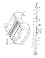
- FIG. 2 is a semi-schematic exploded view of the tonneau cover system disposed over and covering the cargo bed of the vehicle.
- FIG. 3 is a perspective cross-sectional view of a portion of the cargo bed and a portion of the tonneau cover system mounted to the cargo bed.
- FIG. 3A is a perspective cross-sectional view of another portion of the cargo bed and another portion of the tonneau cover system mounted to the cargo bed.
- FIG. 4 is a semi-schematic cross-sectional view of a portion of the cargo bed and a portion of the tonneau cover system mounted to the cargo bed.
- FIG. 5 is a semi-schematic exploded view of another embodiment of the tonneau cover system disposed over and covering the cargo bed of the vehicle.
- FIG. 6 is a top perspective view of the tonneau cover system.
- FIG. 7 is a bottom perspective view of the plurality of panels, a plurality of hinges, a hinge assembly, and a frame of the tonneau cover system, with the frame including outer and inner frame members.
- FIG. 8 is another bottom perspective view of the plurality of panels, the plurality of hinges, the hinge assembly, and frame of the tonneau cover system of FIG. 7 , with a portion of the inner frame members removed to expose a channel with first and second latch mechanisms at least partially disposed in the channel.
- FIG. 9 is a semi-schematic, perspective view of the cargo bed of the vehicle with the plurality of panels disposed over and covering the cargo bed.
- the plurality of panels includes first, second, third, and fourth panels, with each of the first, second, and third panels in a closed position.
- FIG. 10 is a cross-sectional view of the plurality of panels taken along line 10 - 10 in FIG. 9 . Cross-hatching has been removed from FIG. 10 for purposes of simplifying the drawing.
- FIG. 11 is a semi-schematic, perspective view of the cargo bed of the vehicle with the plurality of panels disposed over and partially covering the cargo bed, with the first panel in an opened position and each of the second and third panels in the closed position.
- FIG. 12 is a cross-sectional view of the cover assembly taken along line 12 - 12 in FIG. 11 . Cross-hatching has been removed from FIG. 12 for purposes of simplifying the drawing.
- FIG. 13 is a semi-schematic, perspective view of the cargo bed of the vehicle with the plurality of panels disposed over and partially covering the cargo bed, with the third panel in the opened position and each of the first and second panels in the closed position.
- FIG. 13 also illustrates the third panel located over the second panel to define an intermediate folded position of the tonneau cover system.
- FIG. 14 is a cross-sectional view of the cover assembly taken along line 14 - 14 in FIG. 13 . Cross-hatching has been removed from FIG. 14 for purposes of simplifying the drawing.
- FIG. 15 is a semi-schematic, perspective view of the cargo bed of the vehicle with the plurality of panels disposed over and partially covering the cargo bed, with the second and third panels in an opened position and the first panel in the closed position.
- FIG. 15 also illustrates the second and third panels, as a unit, located over the fourth panel and a portion of the first panel to define a final folded position of the tonneau cover system.
- FIG. 16 is a cross-sectional view of the cover assembly taken along line 16 - 16 of FIG. 15 . Cross-hatching has been removed from FIG. 16 for purposes of simplifying the drawing.
- FIG. 17 is a perspective view of a portion of the tonneau cover system including a portion of the fourth panel, a portion of the side rail, and a mounting mechanism for mounting the fourth panel to the side rail.
- FIG. 17 also illustrates the mounting mechanism in a locked position.
- FIG. 18 is a perspective view of a portion of the tonneau cover system including a portion of the fourth panel, a portion of the side rail, and the mounting mechanism for mounting the fourth panel to the side rail.
- FIG. 18 also illustrates the mounting mechanism in a stowed position.
- FIG. 19 is a bottom perspective view of a portion of the third panel, a portion an outer frame member, a portion of an inner frame member, a channel defined in the inner frame member, and a latch mechanism at least partially disposed in the channel.
- FIG. 19 also illustrates a rearward release device accessible from the bottom of the third panel for moving the latch mechanism from a latch position to an unlatch position.
- FIG. 20 is a bottom perspective view of a portion of the first panel, a portion of an outer frame member, a portion of an inner frame member, a channel defined in the inner frame member, and a latch mechanism at least partially disposed in the channel.
- FIG. 20 also illustrates a forward release device accessible from the bottom of the first panel for moving the latch mechanism from a latch position to an unlatch position.
- FIG. 21 is a cross-sectional view of the second panel pivotally coupled to the fourth panel by a hinge assembly, and the first panel pivotally coupled to the fourth panel by single hinge according to an embodiment of the present disclosure.
- FIG. 22 is a cross-sectional view of the second panel pivotally coupled to the third panel by another single hinge.
- FIG. 22A is an exploded view of the cross-section shown in FIG. 22 .
- FIG. 23 is a cross-sectional view of a hinge according to another embodiment of the present disclosure.
- FIG. 24 is a cross-sectional, perspective view of the hinge of FIG. 23 .
- FIG. 25 is a cross-sectional view of a hinge according to yet another embodiment of the present disclosure.
- FIG. 26 is a cross-sectional, perspective view of the hinge of FIG. 25 .
- the tonneau cover system 10 may be disposed over and at least partially cover a cargo bed 12 of a vehicle 14 .
- the vehicle 14 is a pickup truck including the cargo bed 12
- the tonneau cover system 10 is disposed over and at least partially covers the cargo bed 12 .
- the cargo bed 12 has a header 16 , a tailgate 18 , and opposing sides 20 , 22
- the tonneau cover system 10 is disposed over and coupled to the opposing sides 20 , 22 .
- the cargo bed 12 has a width W CB extending between the opposing sides 20 , 22 , and a length L CB extending between the header 16 and the tailgate 18 .
- the vehicle 14 has a front end 24 and a tail end 26 , and the vehicle 14 has a length L V extending between the front 24 and tail 26 ends.
- the vehicle 14 further has a width W V extending between the opposing sides 20 , 22 of the cargo bed 12 . As shown, the width W V of the vehicle 14 is the same as the width W CB of the cargo bed 12 .
- the vehicle 14 further defines a longitudinal axis A LV extending along the length L V of the vehicle 14 , and a width-wise axis A W extending along the width W V of the vehicle 14 .
- the tonneau cover system 10 is described in detail below as being coupled to the cargo bed 12 of the vehicle 14 . It is to be appreciated, however, that the tonneau cover system 10 could alternatively be used for covering another space defined by the vehicle 14 , not limited to the cargo bed 12 . For instance, the tonneau cover system 10 could be used for covering a passenger compartment of a vehicle, a storage compartment of a vehicle, etc. It is also to be appreciated that the tonneau cover system 10 can be used for other purposes not specifically related to vehicles, such as for homes, buildings, boats, etc.
- the tonneau cover system 10 includes first 28 and second 30 side rails each adapted to be mounted to the vehicle 14 .
- the first side rail 28 is parallel with and mounted to one of the sides 20 of the cargo bed 12
- the second side rail 30 is parallel with and mounted to the other side 22 of the cargo bed 12 .
- the side rails 28 , 30 extend at least partially along the respective side 20 , 22 of the cargo bed 12 , and extend along at least a portion of the length L CB of the cargo bed 12 .
- the side rails 28 , 30 extend along the entire length L CB of the cargo bed 12 .
- the side rails 28 , 30 are discontinuous, with each side rail 28 , 30 having a plurality of strikers 23 , 25 distributed at preselected locations along the sides 20 , 22 of the cargo bed 12 .
- the side rail 28 is mounted to the side 20 of the cargo bed 12 with a seal 27 disposed between the side rail 28 and the side 20 .
- the side rail 30 is mounted to the other side 22 of the cargo bed 12 with another seal 29 disposed between the side rail 30 and the side 22 .
- each of the opposing sides 20 , 22 has an interior surface 32
- each of the side rails 28 , 30 has an exterior surface 34 .
- the opposing sides 20 , 22 and the side rails 28 , 30 are semi-schematically shown in the figures.
- the side rails 28 , 30 could directly abut the sides 20 , 22 of the cargo bed 12 .
- the configuration of the exterior surface 34 of the side rails 28 , 30 could be complementary to a portion of the interior surface 32 of the respective sides 20 , 22 of the cargo bed 12 .
- the first side rail 28 fits against and/or within the complementary portion of the interior surface 32 of the one side 20
- the second side rail 30 fits against and/or within the complementary portion of the interior surface 32 of the other side 22 .
- the side rails 28 , 30 may be mounted to the respective sides 20 , 22 of the cargo bed 12 utilizing any suitable fastening mechanism, such as with one or more fasteners, clamps, latches, and/or the like.
- the side rail 30 has a body 31 and opposing, substantially parallel legs 33 , 35 extending from the body 31 to define a substantially C-shaped configuration.
- the side rail 28 also has a body 31 and opposing, substantially parallel legs 33 , 35 extending from the body 31 to define a substantially C-shaped configuration.
- each striker 23 , 25 also defines the substantially C-shaped configuration. As shown in FIGS.
- the leg 35 of the second side rail 30 defines a slot 68 for receiving a bracket 66 of a mounting mechanism 62 for fixing a fourth panel or spacer bar 44 to the side rail 30 .
- the first side rail 28 also defines a slot for receiving another bracket of another mounting mechanism for fixing the fourth panel or spacer bar 44 to the side rail 28 . Further details of the mounting mechanism 62 are set forth below.
- the leg 33 of the first side rail 28 (or striker 23 , 25 ) defines a receiving feature for receiving a catch 80 of latch mechanisms 82 , 83 adjacent the first side rail 28
- the leg 33 of the second side rail 30 defines a receiving feature for receiving a catch 80 of the latch mechanisms 82 , 83 adjacent the second side rail 30
- the latch mechanisms 82 are coupled to a first panel 38 of the plurality of panels of the tonneau cover system 10
- the latch mechanisms 83 are coupled to a third panel 42 of the plurality of panels of the tonneau cover system 10 . Details of the latch mechanism 82 , 83 are also set forth below at least with reference to FIGS. 19 and 20 . It is to be understood that the side rail 28 has the same configuration as the side rail 30 described above.
- first 28 and second 30 side rails may have the body 31 and a single leg 33 to define a substantially L-shaped configuration.
- each striker 23 , 25 also defines the substantially L-shaped configuration.
- the leg 33 of the side rails 28 , 30 could operate as the receiving feature for receiving the catch 80 of the respective latch mechanisms 82 , 83 .
- side rails 28 , 30 have been described above as having a substantially C-shaped or L-shaped configuration, it is to be appreciated that the side rails 28 , 30 (or strikers 23 , 25 ) can alternatively have any suitable configuration that defines the receiving feature 33 .
- the tonneau cover system 10 further comprises a plurality of panels coupled to the side rails 28 , 30 and defining a longitudinal axis A LP adapted to be along the length L V of the vehicle 14 .
- the longitudinal axis A LP is the same as the longitudinal axis A LV defined by the vehicle 14 .
- the plurality of panels includes a first panel 38 , a second panel 40 spaced from the first panel 38 , a third panel 42 adjacent the second panel 40 , and the fourth panel 44 disposed between the first 38 and second 40 panels with the fourth panel 44 fixed to the first 28 and second 30 side rails.
- the plurality of panels further includes a fifth panel 46 , which is part of a hinge assembly 48 .
- the hinge assembly 48 is described in further detail below.
- the tonneau cover system 10 does not include or utilize side rails.
- the plurality of panels 38 , 40 , 42 , 44 , 46 is directly coupled to the opposing sides 20 , 22 of the cargo bed 12 .
- each of the opposing sides 20 , 22 may have or define a bed rail, and the plurality of panels 38 , 40 , 42 , 44 , 46 is directly coupled to the bed rails.
- the bed rails also define a suitable receiving feature for receiving the catch 80 of the latch mechanism 82 , 83 coupled to the plurality of panels of the tonneau cover system 10 .
- the plurality of panels includes the first 38 , second 40 , third 42 , fourth 44 , and fifth 46 panels.
- first panel 38 the configuration of just the first panel 38 is shown in FIGS. 3 and 4
- the second 40 , third 42 , fourth 44 , and fifth 46 panels have substantially the same configuration.
- each of the panels 38 , 40 , 42 , 44 , 46 is formed of a rigid material.
- the rigid material may be selected from any material exhibiting a suitable degree of resistance to deformation in response to an applied force or load.
- the panels 38 , 40 , 42 , 44 , 46 are formed of a lightweight rigid material.
- Non-limiting examples of suitable rigid materials include metals (such as aluminum, aluminum alloys, steels, and/or the like), polymers such as a thermoplastic olefin, fiber-reinforced plastics, composites, laminates, and/or combinations thereof.
- the panel 38 has opposing top 58 and bottom 60 sheets or surfaces formed of the rigid material, and a polymeric core 61 disposed between the top 58 and bottom 60 surfaces.
- each of the remaining panels 40 , 42 , 44 , 46 also has opposing top 58 and bottom 60 sheets or surfaces formed of the rigid material, and a polymeric core 61 disposed between the top 58 and bottom 60 surfaces.
- the polymeric core 61 can be a polymeric foam, such as a polystyrene foam or other suitable foamed resin.
- the polymeric core 61 can otherwise have a honeycomb configuration. While polymeric cores are typical, the core could alternatively be formed of or include a metal (such as aluminum, an aluminum alloy, a steel, and/or the like). In another embodiment, each of the panels 38 , 40 , 42 , 44 , 46 could be solid panels formed of the rigid material.
- each of the panels 38 , 40 , 42 , 44 , 46 has a substantially rectangular configuration, and each has opposing first 50 and second 52 ends and opposing first 54 and second 56 sides. It is to be understood that the rectangular configuration is dependent, at least in part, on the dimensions of the cargo bed 12 of the vehicle 14 .
- Each of the panels 38 , 40 , 42 , 44 , 46 also has a length L P defined between the opposing ends 50 , 52 along the longitudinal axis A LP , and has a width W P defined between opposing sides 54 , 56 .
- one side 54 of each of the panels 38 , 40 , 42 , 44 , 46 is adjacent and substantially parallel to the first side rail 28
- the other side 56 of each of the panels 38 , 40 , 42 , 44 , 46 is adjacent and substantially parallel to the second side rail 30 .
- the length L P of the fourth panel 44 is smaller than the length L P of each of the first 38 , second 40 , and third 42 panels.
- the length L P of the fourth panel 44 is smaller than the length L P of each of the first 38 , second 40 , and third 42 panels, and the length L P of the fourth panel 44 is larger than the length L P of the fifth panel 46 .
- Each of the first 38 , second 40 , third 42 , fourth 44 , and fifth 46 panels has a perimeter or periphery 45
- each of the panels 38 , 40 , 42 , 44 , 46 has a frame 47 disposed about at least a portion of the perimeter 45
- the frame 47 includes a plurality of outer frame members, including a first outer frame member 84 adjacent and substantially parallel to the first side rail 28 and a second outer frame member 86 adjacent and substantially parallel to the second side rail 30 .
- the first 84 and second 86 outer frame members extend along the longitudinal axis A LV , and the first 84 and second 86 outer frame members are substantially parallel to one another.
- the frame 47 further includes a third outer frame member 88 adjacent and substantially parallel to the first end 50 of each of the panels 38 , 40 , 42 , 44 , 46 , and a fourth outer frame member 90 adjacent and substantially parallel to the second end 52 of the each of the panels 38 , 40 , 42 , 44 , 46 .
- the third 88 and fourth 90 outer frame members extend along the width-wise axis A W between the first 84 and second 86 outer frame members.
- the third 88 and fourth 90 outer frame members are substantially parallel to one another.
- the outer frame members 84 , 86 , 88 , 90 are typically discontinuous. In other words, neither the first 84 and second 86 outer frame members directly touch the third 88 and fourth 90 outer frame members. Additionally, the outer frame members 84 , 86 , 88 , 90 of adjacent panels 38 , 40 , 42 , 44 , 46 do not directly touch one another. The discontinuity of the outer frame members 84 , 86 , 88 , 90 enables the panels 38 , 40 , 42 , 44 , 46 to pivot relative to one another when opening one or more of the first 38 , second 40 , and third 42 panels for access to the interior of the cargo bed 12 .
- the frame 47 includes a first inner frame member 92 coupled to the first panel 38 and extending along the width-wise axis A W between the first 84 and second 86 outer frame members.
- the frame 47 further includes a second inner frame member 94 coupled to the third panel 42 and extending along the width-wise axis A W between the first 84 and second 86 outer frame members.
- the first inner frame member 92 defines a channel 96 for receiving and supporting the latch mechanism(s) 82 and a forward release device 98 for actuating the latch mechanism(s) 82 to unlatch the first panel 38 from the side rails 28 , 30 .
- the second inner frame member 94 defines a channel 97 for receiving and supporting the latch mechanisms 83 and a rearward release device 99 for actuating the latch mechanism 83 to unlatch the third panel 42 from the side rails 28 , 30 .
- the first inner frame member 92 defines the channel 96 for receiving and supporting the latch mechanism(s) 82 and the forward release device 98 for actuating the latch mechanism(s) 82 to unlatch the first panel 38 from the sides 20 , 22 of the cargo bed 12 adjacent the header 16 .
- the second inner frame member 94 defines the channel 97 for receiving and supporting the latch mechanisms 83 and the rearward release device 99 for actuating the latch mechanisms 83 to unlatch the third panel 42 from the sides 20 , 22 of the cargo bed 12 adjacent the tailgate 18 .
- the frame 47 further includes a third inner frame member 95 coupled to the fourth panel 44 and extending along the width-wise axis A W between the first 84 and second 86 outer frame members, see FIGS. 17 and 18 .
- the third inner frame member 95 also defines a channel 96 for receiving and supporting the mounting mechanism 62 for fixing the fourth panel 44 to the first 28 and second 30 side rails.
- the tonneau cover system 10 includes a first seal 85 extending along the longitudinal axis A CB and disposed between the first side rail 28 and the side 20 of the cargo bed 12 .
- the tonneau cover system 10 further includes a second seal 87 extending along the longitudinal axis A CB and disposed between the second side rail 30 and the side 22 of the cargo bed 12 .
- the first seal 85 is coupled to the first side rail 28 and abuts the side 20 of the cargo bed 12
- the second seal 87 is coupled to the second side rail 30 and abuts the side 22 of the cargo bed 12 .
- the seals 85 , 87 form a seal at an interface between the frame 47 of the tonneau cover system 10 and the respective side rails 28 , 30 .
- the first seal 85 coupled to the tonneau cover system 10 also abuts the side 20 of the cargo bed 12
- the second seal 87 coupled to the tonneau cover system 10 also abuts the side 22 of the cargo bed 12 .
- the seals 85 , 87 also form a seal at an interface between the frame 47 of the tonneau cover system 10 and the respective sides 20 , 22 of the cargo bed 12 .
- the plurality of panels is arranged such that the first panel 38 is positioned adjacent the header 16 of the cargo bed 12 , the fourth panel 44 is positioned adjacent the first panel 38 , the hinge assembly 48 including the fifth panel 46 is positioned adjacent the fourth panel 44 , the second panel 40 is positioned adjacent the hinge assembly 48 , and the third panel 42 is positioned adjacent the second panel 40 .
- the third panel 42 is also positioned adjacent the tailgate 18 of the cargo bed 12 .
- the first panel 38 of the plurality of panels is pivotally coupled to the fourth panel 44 to enable the first panel 38 to pivot relative to the fourth panel 44 .
- the tonneau cover system 10 includes a second hinge 72 mounted to the first 38 and fourth 44 panels to enable the first panel 38 to pivot relative to the fourth panel 44 .
- the second hinge 72 enables the first panel 38 to pivot between a closed position (as shown in FIGS. 9 and 10 ) and an opened position (as shown in FIGS. 11 and 12 ).
- the tonneau cover system 10 includes the side rails 28 , 30
- the second end 52 of the first panel 38 is adjacent the side rails 28 , 30 when in the closed position (as shown in FIG. 9 ).
- the first panel 38 could engage the sides 20 , 22 of the cargo bed 12 adjacent the header 16 or a discontinuous side rail (or striker 23 , 25 ) when in the closed position.
- the opened position or partially opened position which is any position between the closed position and the fully opened position
- the second end 52 of the first panel 38 is spaced from the side rails 28 , 30 (as shown in FIG. 11 ).
- the first panel 38 provides partial access to the cargo bed 12 proximate the header 16 .
- the third panel 42 is pivotally coupled to the second panel 40 to enable the third panel 42 to pivot relative to the second panel 40 and to permit the third panel 42 to be located over the second panel 40 .
- the tonneau cover system 10 further includes a first hinge 70 mounted to the second 40 and third 42 panels to enable the third panel 42 to pivot relative to the second panel 40 .
- the first hinge 70 is mounted to the second end 52 of the third panel 42 .
- the first hinge 70 enables the third panel 42 to pivot between a closed position (as shown in FIGS. 9 and 10 ) and an opened position (as shown in FIGS. 13 and 14 ).
- the closed position the first end 50 of the third panel 42 is adjacent the side rails 28 , 30 (as shown in FIG. 9 ).
- the opened position or partially opened position which is any position between the closed position and the fully opened position
- the first end 50 of the third panel 42 is spaced from the side rails 28 , 30 (as shown in FIG. 13 ).
- the third panel 42 is in a fully opened position when the third panel 42 is located over the second panel 40 and into an intermediate folded position of the tonneau cover system 10 .
- the third panel 42 provides partial access to the cargo bed 12 proximate the tailgate 18 .
- the second 40 and third 42 panels provide partial access to the cargo bed 12 when in the intermediate folded position.
- the second panel 40 is pivotally coupled to the fourth panel 44 so that the second 40 and third 42 panels pivot relative to the fourth panel 44 as a unit from the intermediate folded position to a final folded position of the tonneau cover system 10 .
- the second 40 and third 42 panels as a unit, are located over the fourth panel 44 and a portion of the first panel 38 when in the final folded position. Accordingly, the first panel 38 remains in the closed position when the second 40 and third 42 panels are in the final folded position.
- the first 38 , second 40 , third 42 , and fourth 44 panels are parallel to each other when the second 40 and third 42 panels are in the final folded position.
- Partial access to the cargo bed 12 , adjacent the tailgate 18 is typically achieved when the second 40 and third 42 panels, as a unit, are in the final folded position. Said differently, the second 40 and third 42 panels provide partial access to the cargo bed 12 when in the final folded position.
- the first panel 38 is pivotable relative to the fourth panel 44 in a first direction and the third panel 42 is pivotable relative to the fourth panel 44 in a second direction.
- the second direction is opposite the first direction.
- the first panel 38 pivots relative to the fourth panel 44 in a direction towards the tailgate 18
- the third panel 42 pivots relative to the second panel 40 in a direction towards the header 16 .
- the first panel 38 is pivotable relative to the fourth panel 44 in the first direction
- the second 40 and third 42 panels are pivotable relative to the fourth panel 44 in the second direction, where the first direction is opposite the second direction.
- the first panel 38 pivots relative to the fourth panel 44 in a direction towards the tailgate 18
- the second 40 and third 42 panels as a unit, pivot relative to the fourth panel 44 in a direction towards the header 16 .
- the fourth panel 44 is fixed to the first 28 and second 30 side rails, and remains fixed to the side rails 28 , 30 when the first 38 , second 40 , and third 42 panels pivot to provide access to the interior of the cargo bed 12 .
- the fourth panel 44 is fixed to the sides 20 , 22 , and remains fixed to the sides 20 , 22 of the cargo bed 12 when the first 38 , second 40 , and third 42 panels pivot to provide access to the interior of the cargo bed 12 .
- the fourth panel 44 may be referred to as a spacer bar which is fixed to the side rails 28 , 30 , or fixed to the sides 20 , 22 of the cargo bed 12 .
- the spacer bar is also formed of a rigid material having the top 58 and bottom 60 surfaces to define a panel configuration.
- the tonneau cover system 10 includes the mounting mechanism 62 located at each of the first 54 and second 56 sides of the fourth panel 44 .
- the mounting mechanism 62 at the first side 54 of the fourth panel 44 fixes the first side 54 to the first side rail 28
- the mounting mechanism 62 at the second side 54 of the fourth panel 44 fixes the second side 56 to the second side rail 30 .
- the mounting mechanism 62 is disposed within and secured to the channel 96 defined in the third inner frame member 95 .
- the mounting mechanism 62 includes a housing 64 defining an opening 100 , and is coupled to the bottom surface 60 of the fourth panel 44 . More particularly, the housing 64 is disposed within the channel 96 and mounted to the third inner frame member 95 .
- the mounting mechanism 62 further includes a bracket 66 coupled to the housing 64 and moveable between stowed and locked positions.
- the bracket 66 is formed of a metal or another suitably strong material.
- the bracket 66 has opposing ends 102 , 104 , with one end 102 coupled to the housing 64 and the other end 104 having a lip 106 that is insertable into the slot 68 defined in the leg 35 of the side rail 28 , 30 .
- the lip 106 of the end 104 engages the side 20 , 22 of the cargo bed 12 directly.
- the end 102 of the bracket 66 is coupled to the housing 64 with a fastener 108 .
- the end 102 of the bracket 66 defines an aperture (not shown), and the fastener 108 is disposed through the aperture and secured to the end 102 .
- the fastener 108 is also disposed within the opening 100 defined in the housing 64 such that the fastener 108 can move and/or pivot within the opening 100 . In this way, the bracket 66 can be moved between the locked and stowed positions.
- the fastener 108 may include a head 110 and a threaded body 112 extending from the head.
- the threaded body 112 may be inserted into the opening 100 defined in the housing 64 with the head 110 abutting an underside of the housing 64 .
- the threaded body 112 is disposed through the aperture defined in the bracket 66 .
- the bracket 66 can be moved into the locked position by pivoting the fastener 108 to position the bracket 66 such that the lip 106 is aligned with the slot 68 defined in the side rail 28 , 30 .
- the lip 106 is inserted into the slot 68 , and the fastener 108 is tightened within the opening 100 utilizing a suitable tightening mechanism 114 , such as one or more nuts, etc.
- the bracket 66 is secured in the locked position, the side 54 , 56 of the fourth panel 44 is secured to the side rail 28 , 30 .
- the fourth panel 44 is unable to move during the pivoting motion of the first 38 , second 40 , and third 42 panels.
- the fourth panel 22 can be released from the side rails 28 , 30 by manually moving the bracket 66 into the stowed position.
- the bracket 66 can be moved into the stowed position by loosening the tightening mechanism 114 to release the lip 106 from the slot 38 defined in the side rail 28 , 30 , and then pivoting the fastener 108 to move the bracket 66 away from the side rail 28 , 30 to a position against the channel 96 defined by the third inner frame member 95 .
- the tightening mechanism 114 may be re-tightened to secure the bracket 66 in the stowed position.
- the first panel 38 pivots relative to the fourth panel 44 while the fourth panel 44 remains fixed to the side rails 28 , 30 .
- the third panel 42 pivots relative to the second panel 40 to permit the third panel 42 to be located over the second panel 40 while the fourth panel 44 remains fixed to the side rails 28 , 30 to define the intermediate folded position of the tonneau cover system 10 .
- the second 40 and third 42 panels pivot relative to the fourth panel 44 , as a unit, from the intermediate folded position to the final folded position located over the fourth panel 44 and a portion of the first panel 38 while the fourth panel 44 remains fixed to the side rails 28 , 30 .
- the tonneau cover system 10 includes buckles 175 and the plurality of panels includes straps (not shown).
- the straps are tied or otherwise attached to the buckles 175 to secure the panels in the final folded position. This is desirable, for example, when the vehicle 14 is being operated while the tonneau cover system 10 is in the final folded position.
- the tonneau cover assembly 10 further includes the hinge assembly 48 .
- the hinge assembly 48 has the fifth panel 46 , a third hinge 74 , and a fourth hinge 76 .
- the third hinge 74 is mounted to the fourth 44 and fifth 46 panels and the fourth hinge 76 is mounted to the second 40 and fifth 46 panels such that the hinge assembly 48 is mounted between the second 40 and fourth 44 panels.
- the hinge assembly 48 operates as a unit and enables the second 40 and third 42 panels to pivot relative to the fourth panel 44 , as a unit, from the intermediate folded position to the final folded position of the tonneau cover assembly 10 .
- the hinge assembly 48 is positioned such that the fifth panel 46 is transverse to the fourth panel 44 . This is shown in FIGS. 15 and 16 . However, the fifth panel 46 is parallel to the fourth panel 44 when the second 40 and third 42 panels are in the intermediate folded position (again, where the third panel 42 is located over the second panel 40 ). Details of the first 70 , second 72 , third 74 , and fourth 76 hinges are described below.
- the first panel 38 further includes at least one latch mechanism 82 for latching the first panel 38 to at least one of the first 28 and second 30 side rails.
- the first panel 38 has a single latch mechanism 82 for latching the first panel 38 to one of the first 28 and second 30 side rails.
- the first panel 38 has two latch mechanisms 82 , with one of the latch mechanisms 82 at one side 54 of the first panel 38 for latching the first panel 38 to the first side rail 28 , and the other latch mechanism 82 at the other side 56 of the first panel 38 for latching the first panel 38 to the second side rail 28 .
- the latch mechanism 82 coupled to the first panel 38 is shown at least in FIG. 20 .
- the latch mechanism 82 has the catch 80 moveable between latch and unlatch positions.
- the catch 80 is biased toward the side rail 28 , 30 and towards the latch position. In the latch position, the catch 80 is captured within the receiving feature 33 defined in the side rail 28 , 30 .
- the catch 80 is biased toward the latch position by a biasing spring (not shown).
- the latch mechanism 82 further includes a catch housing 116 mounted to the first inner frame member 92 , and the catch 80 is partially disposed and supported in the catch housing 116 . When in the latch position, the catch 80 engages the receiving feature 33 defined in the side rail 28 , 30 to latch the first panel 38 to the side rail 28 , 30 .
- the first panel 38 further has the forward release device 98 coupled to the latch mechanism(s) 82 .
- the forward release device 98 is coupled to the latch mechanism(s) 82 with at least one cable 118 .
- the forward release device 98 includes a forward handle 120 coupled to the top surface 58 of the first panel 38 .
- a cover 121 is coupled to bottom surface 60 and is used to cover the release device 98 from the bottom side. With this configuration, an operator can access the forward handle 120 from a position above the tonneau cover system 10 .
- the forward release device 98 is actuatable to retract the cable 118 and release the catch 80 of the latch mechanism(s) 82 from the receiving feature 33 to move the catch 80 from the latch position to the unlatch position. Accordingly, when actuated, the forward release device 98 retracts the cable 118 and releases the catch 80 from the receiving feature 33 to unlatch the first panel 38 from the side rail 28 , 30 .
- the forward release device 98 may be coupled to one of the latch mechanisms 82 with one cable 118 , and may be coupled to the other latch mechanism 82 with another cable 118 .
- the forward release device 98 may be actuated to retract and release the catch 80 of one of the latch mechanisms 82 simultaneously with the catch 80 of the other latch mechanism 82 . In this way, the forward release device 98 retracts and releases the respective catches 80 of the two latch mechanisms 82 from the respective receiving features 33 defined in the first 28 and second 30 side rails to unlatch the first panel 38 from the first 28 and second 30 side rails.
- the third panel 42 also includes at least one latch mechanism 83 for latching the third panel 42 to at least one of the first 28 and second 30 side rails.
- the third panel 42 has a single latch mechanism 83 for latching the third panel 42 to one of the first 28 and second 30 side rails.
- the third panel 42 has two latch mechanisms 83 , with one of the latch mechanisms 83 at one side 54 of the third panel 42 for latching the third panel 42 to the first side rail 28 , and the other latch mechanism 83 at the other side 56 of the third panel 42 for latching the third panel 42 to the second side rail 30 .
- the latch mechanism 83 coupled to the first panel 38 is shown at least in FIG. 19 .
- the latch mechanism 83 has the catch 80 moveable between latch and unlatch positions.
- the catch 80 is biased toward the side rail 28 , 30 and towards the latch position. In the latch position, the catch 80 is captured within the receiving feature 33 defined in the side rail 28 , 30 .
- the catch 80 is biased toward the latch position by a biasing spring.
- the latch mechanism 82 further includes a catch housing 116 mounted to the first inner frame member 92 , and the catch 80 is partially disposed and supported in the catch housing 116 . When in the latch position, the catch 80 engages the receiving feature 33 defined in the side rail 28 , 30 to latch the first panel 38 to the side rail 28 , 30 .
- the third panel 42 further has a rearward release device 99 coupled to the latch mechanism(s) 83 .
- the rearward release device 99 is coupled to the latch mechanism(s) 83 with at least one cable 118 .
- the rearward release device 98 includes a rearward handle 120 coupled to the bottom surface 60 of the third panel 42 . With this configuration, an operator can access the rearward handle 120 from a position below the tonneau cover system 10 , such as by opening the tailgate 18 and reaching under the third panel 42 .
- the rearward release device 99 is actuatable to retract and release the catch 80 from the receiving feature 33 to move the catch 80 from the latch position to the unlatch position. Accordingly, when actuated, the rearward release device 99 retracts and releases the catch 80 from the receiving feature 99 to unlatch the third panel 42 form the side rail 28 , 30 .
- the rearward release device 99 may be coupled to one of the latch mechanisms 83 with one cable 118 , and may be coupled to the other latch mechanism 83 with another cable 118 .
- the rearward release device 99 may be actuated to retract and release the catch 80 of one of the latch mechanisms 83 simultaneously with the catch 80 of the other latch mechanism 83 . In this way, the rearward release device 99 retracts and releases the respective catches 80 of the two latch mechanisms 83 from the respective receiving features 33 defined in the first 28 and second 30 side rails to unlatch the third panel 42 from the first 28 and second 30 side rails.
- first 70 , second 72 , third 73 , and fourth 74 hinges are described in detail below at least with reference to FIGS. 21-26 .
- Each hinge 70 , 72 , 74 , 76 is mounted to adjacent panels to enable one of the adjacent panels to pivot relative to another of the adjacent panels.
- the first hinge 70 is mounted to the second 40 and third 42 panels to enable the third panel 42 to pivot relative to the second panel 40 .
- the second hinge 72 is mounted to the first 38 and fourth 44 panels to enable the first panel 38 to pivot relative to the fourth panel 44 .
- each of the hinges 70 , 72 , 74 , 76 has a width W h extending along the width-wise axis A W of the vehicle 14 , and the hinges 70 , 72 , 74 , 76 extend along at least a portion of the width W P of the panels 38 , 40 , 42 , 44 .
- first hinge 70 which is mounted between the adjacent second 40 and third 42 panels. It is to be appreciated that the embodiments of the hinge described below are applicable to each of the first hinge 70 , the second hinge 72 , the third hinge 74 , and the fourth hinge 76 .
- the hinge 70 has a body 122 formed of an elastomeric material and having first 124 and second 126 portions.
- the hinge 70 further has a first securing member 128 integral with and extending from the first portion 124 of the body 122 , and has a second securing member 130 integral with and extending from the second portion 126 of the body 122 .
- the first securing member 128 is engaged with one of the panels 40 , 42
- the second securing member 130 is engaged with the other panel 40 , 42 .
- the first securing member 128 is engaged with the second panel 40
- the second securing member 130 is engaged with the third panel 42 .
- each of the first 128 and second 130 securing members has a circular or substantially circular configuration.
- one or more of the first 128 and second 130 securing members can have a circular configuration, an oval configuration, a quadrilateral configuration, a diamond configuration, a heart-shaped configuration, a teardrop-shaped configuration, a triangular configuration, and/or the like, and/or combinations thereof.
- the first 128 and second 130 securing members may have any configuration so long as the first 128 and second 130 securing members suitably mounted to the respective lower cavities 134 , 138 .
- the first 128 and second 130 securing members can have any suitable size. In the embodiment shown, the first 128 and second 130 securing members have the same or substantially same size. Alternatively, the size of the first securing member 128 can be different from the size of the second securing member 130 .
- the second panel 40 has an upper securing cavity 132 and a lower securing cavity 134
- the third panel 40 has an upper securing cavity 136 and a lower securing cavity 138 .
- the second panel 40 has the frame 47 , and the upper 132 and lower 134 securing cavities are defined in the frame 47 .
- the third panel 42 has the frame 47 , and the upper 136 and lower 138 securing cavities are defined in the frame 47 .
- At least a portion of the first securing member 128 is disposed within the lower securing cavity 134 of the second panel 40 , and at least a portion of the second securing member 130 is disposed within the lower securing cavity 138 of the third panel 42 .
- the first securing member 128 is mounted to the lower securing cavity 134 of the second panel 40
- the second securing member 130 is mounted to the lower securing member 138 of the third panel 42 .
- the body 122 of the hinge 70 further has a first leg 140 with the first securing member 128 mounted to the first leg 140 , and has a second leg 142 with the second securing member 130 mounted to the second leg 142 .
- a portion of the first leg 140 is disposed within the lower securing cavity 134 of the second panel 40
- a portion of the second leg 142 is disposed within the lower securing cavity 138 of the third panel 42
- no portion of the first leg 140 is disposed within the lower securing cavity 134 of the second panel 40
- no portion of the second leg 142 is disposed within the lower securing cavity 138 of the third panel 42 .
- the respective lower securing cavities 134 , 138 receive only the first 128 and second 130 securing members.
- the hinge 70 further has a third securing member 144 integral with and extending from the first portion 124 of the body 122 , and a fourth securing member 146 integral with and extending from the second portion 126 of the body 122 .
- the body 122 has a first flange 148 extending from the first portion 124 with the third securing member 144 extending from the first flange 148 , and has a second flange 150 extending from the second portion 126 with the fourth securing member 146 extending from the second portion 126 .
- the first 148 and second 150 flanges are integral with the body 122 .
- the third securing member 144 is integral with the first flange 148
- the fourth securing member 146 is integral with the second flange 150 .
- the first flange 148 extends from the first portion 124 of the body 122 in a first direction transverse to the width-wise axis A W
- the second flange 150 extends from the second portion 126 of the body 122 in a second direction transverse to the width-wise axis A W with the second direction opposite the first direction.
- the first and second directions extend along the longitudinal axis A LV of the vehicle 14 .
- the third securing member 144 extends from the first flange 148 in a third direction transverse to the longitudinal axis A LV and transverse to the width-wise axis A W
- the fourth securing member 146 extends from the second flange 150 in a fourth direction transverse to the longitudinal axis A LV and transverse to the width-wise axis A W .
- the third direction that the third securing member 144 extends from the first flange 148 defines a first vertical axis A V1
- the fourth direction that the fourth securing member 146 extends from the second flange 150 defines a second vertical axis A V2
- the first securing member 128 is aligned with the third securing member 144 along the first vertical axis A V1
- the second securing member 130 is aligned with the fourth securing member 146 along the second vertical axis A V2
- the first securing member 128 is spaced from the third securing member 144
- the second securing member 130 is spaced from the fourth securing member 146 .
- Each of the third 144 and fourth 146 securing members has a neck portion 152 and a main portion 154 extending from the neck portion 152 .
- the main portion 154 is larger in cross-section than the neck portion 152 .
- the main portion 154 has a rectangular configuration in cross-section. It is to be understood that the main portion 154 could have any configuration, such as a circular configuration, an oval configuration, a triangular configuration, a polygonal configuration, a heart-shaped configuration, a teardrop-shaped configuration, and/or the like, and/or combinations thereof.
- the main portion 154 of the third 144 and fourth 146 securing members can have any suitable size.
- main portion 154 of the third 144 and fourth 146 securing members have the same or substantially same size.
- the size of the main portion 154 of the third securing member 144 can be different from the size of the main portion 154 of the fourth securing member 146 .
- the neck portion 152 can have any suitable size and/or configuration.
- the neck portion 152 of the third 144 and fourth 146 securing members have the same or substantially same size.
- the size of the neck portion 152 of the third securing member 144 can be different from the size of the neck portion 152 of the fourth securing member 146 .
- the second panel 40 has the upper securing cavity 132 defined in the frame 47
- the third panel 42 has the upper securing cavity 136 defined in the frame 47 .
- the upper securing cavity 132 is defined in the frame 47 of the second panel 40 open to the upper or top surface 58 of the second panel 40
- the upper securing cavity 136 defined in the frame 47 of the third panel 42 open to the upper or top surface 58 of the third panel 42 .
- At least a portion of the third securing member 144 is disposed within the upper securing cavity 132 defined the frame 47 of the second panel 40
- at least a portion of the fourth securing member 146 is disposed within the upper securing cavity 136 defined in the frame 47 of the third panel 42 .
- the upper securing cavity 132 defined in the frame 47 of the second panel 40 is spaced from the lower securing cavity 134 defined in the frame 47 of the second panel 40
- the upper securing cavity 136 defined in the frame 47 of the third panel 42 is spaced from the lower securing cavity 138 defined in the frame 47 of the third panel 42 .
- Each of the upper cavities 132 , 136 has a stem portion 156 and a chamber portion 158 with the chamber portion 158 being larger in cross-section than the stem portion 156 .
- the stem portion 156 of the upper securing cavity 132 of the second panel 40 has substantially the same configuration as the neck portion 152 of the third securing member 144
- the stem portion 156 of the of the upper securing cavity 136 of the third panel 42 has substantially configuration as the neck portion 152 of the fourth securing member 146 .
- the stem portion 156 of the upper securing cavity 132 of the second panel 40 is slightly larger in cross-section compared to the neck portion 152 of the third securing member 144 so that the neck portion 152 of the third securing member 144 fits within the stem portion 156 of the upper securing cavity 132 of the second panel 40 .
- the stem portion 156 of the upper securing cavity 136 of the third panel 42 is slightly larger in cross-section compared to the neck portion 152 of the fourth securing member 146 so that the neck portion 152 of the fourth securing member 146 fits within the stem portion 156 of the upper securing cavity 136 of the third panel 42 .
- the chamber portion 158 of the upper securing cavity 132 of the second panel 40 has substantially the same configuration as the main portion 154 of the third securing member 144
- the chamber portion 156 of the of the upper securing cavity 136 of the third panel 42 has substantially configuration as the neck portion 152 of the fourth securing member 146
- the chamber portion 158 of the upper securing cavity 132 of the second panel 40 is slightly larger in cross-section compared to the main portion 154 of the third securing member 144 so that the main portion 154 of the third securing member 144 fits within the chamber portion 158 of the upper securing cavity 132 of the second panel 40 .
- the chamber portion 158 of the upper securing cavity 136 of the third panel 42 is slightly larger in cross-section compared to the main portion 154 of the fourth securing member 146 so that the main portion 154 of the fourth securing member 146 fits within the chamber portion 158 of the upper securing cavity 136 of the third panel 42 .
- the arrangement of the first 128 and third 144 securing members of the first portion 124 of the elastomeric body 122 defines a water path that is relatively complex.
- the arrangement of the second 130 and fourth 146 securing members of the second portion 126 of the elastomeric body 122 defines a water path that is relatively complex.
- the water would have to make several turns (such as around the third securing member 144 and then around the first securing member 128 ) before finding its way through the interface between the body 122 of the hinge 70 and the panel (such as the second panel 40 ).
- water leakage at the interface between the body 122 of the hinge 70 and the panels 40 , 42 is reduced or even prevented, which contributes to improved water management of the tonneau cover system 10 .
- each of the body 122 , the first securing member 128 , the second securing member 130 , the third securing member 144 , and the fourth securing member 146 of the hinge 70 has a substantially smooth surface.
- the hinge 70 further has a plurality of barbs 160 extending from the body 122 with the barbs 160 engaging the second 40 and third 42 panels to form a seal between the body 122 of the hinge 70 and the adjacent panels 40 , 42 .
- the seal formed at the interfaces between the body 122 and the panels 40 , 42 also contributes to improved water management by preventing water (or other liquid) from leaking through these interfaces.
- the barbs 160 are also continuous along the width W h of the hinge 70 .
- the barbs 160 further extend from at least a portion of the first securing member 128 , at least a portion of the second securing member 130 , and combinations thereof.
- the barbs 160 further extend from a least a portion of the third securing member 144 , at least a portion of the fourth securing member 146 , and combinations thereof.
- the plurality of barbs 160 are integral with the body 122 , the first securing member 128 , and the second securing member 130 .
- the plurality of barbs 160 are integral with the body 122 , the first securing member 128 , the second securing member 130 , the third securing member 144 , and the fourth securing member 146 .
- each of the barbs 160 has a common configuration. As shown in FIGS. 23 and 24 , for example, each of the barbs 160 has a triangular configuration in cross-section. In another example, at least one of the barbs 160 has a triangular configuration in cross-section. In addition, the size of the barbs 160 may be the same or different. The barbs 160 may also be formed at selected positions along the body 122 , the first securing member 128 , the second securing member 130 , the third securing member 144 , and the fourth securing member 146 .
- each of the first 140 and second 142 legs of the body 122 have exterior 162 and interior 164 surfaces, and the barbs 160 may be formed at least along the entire exterior surface 164 of each of the first 140 and second 142 legs and partially along the interior surface 162 of each of the first 140 and second 142 legs.
- the barbs 160 are also formed along each of the first 128 and second 130 securing members, and along the neck 152 and main 154 portions of each of the third 144 and fourth 146 securing members.
- Each of the barbs 160 may have a thickness T, and adjacent barbs 160 define a space 166 between the barbs 160 which is larger in cross-section than the thickness T of each of the barbs 160 .
- the barbs 160 includes a series 168 of barbs 160 , with the barbs 160 of the series 168 being equally spaced from one another.
- the body 122 has multiple series 168 of barbs 160 , with the barbs 160 of each of the series 168 being equally spaced from one another.
- At least one of the barbs 160 has a different configuration from another one of the barbs 160 .
- at least one of the barbs 160 has a triangular configuration and at least one of the barbs 160 has a barb body 170 with a round configuration and a tip 172 extending from the barb body 170 .
- each of the first 124 and second 126 portions of the body 122 has a plurality of barbs 160 having the round barb body 170 and the tip 172 , and the first leg 140 , the second leg 142 , the first securing member 128 , and the second securing member 130 each have barbs 160 with a triangular configuration.
- the hinge 70 can alternatively have barbs 160 with any suitable configuration and/or distribution along the body 122 and securing members 128 , 130 , 144 , 146 .
- the barbs 160 could have any suitable configuration, such as the triangular or rounded configuration mentioned above, a rectangular configuration, a polygonal configuration, and/or the like.
- the hinge 70 could have one, two, three, or more different configurations of barbs 160 distributed or formed along at least a portion of the hinge 70 .
- the different configurations of barbs 160 could be randomly formed along at least a portion of the hinge 70 , formed in an alternating pattern along at least a portion of the hinge 70 , formed in series along at least a portion of the hinge 70 , etc.
- the tonneau cover system 10 further comprises a seal 174 extending along the width-wise axis A W of the vehicle 14 .
- the seal 174 is disposed below the elastomeric body 122 of the hinge 70 between the first 128 and second 130 securing members.
- the seal 174 is formed from any suitable elastomeric material.
- the seal 174 is formed from the same material as the elastomeric body 122 of the hinges 70 , 72 , 74 , 76 .
- the seal 174 is located between adjacent panels, and is coupled to one of the adjacent panels and abuts the other of the adjacent panels.
Abstract
Description
Claims (20)
Priority Applications (1)
| Application Number | Priority Date | Filing Date | Title |
|---|---|---|---|
| US15/536,187 US10189339B2 (en) | 2016-07-27 | 2017-04-25 | Tonneau cover system for a cargo bed of a vehicle |
Applications Claiming Priority (12)
| Application Number | Priority Date | Filing Date | Title |
|---|---|---|---|
| CN201620796716U | 2016-07-27 | ||
| CN201610597765.7 | 2016-07-27 | ||
| CN201620796716.1 | 2016-07-27 | ||
| CN201620796716.1U CN205836642U (en) | 2016-07-27 | 2016-07-27 | A kind of folding till(top) |
| CN201610597765.7A CN107662537A (en) | 2016-07-27 | 2016-07-27 | A kind of folding till(top) |
| CN201610597765 | 2016-07-27 | ||
| US201662414384P | 2016-10-28 | 2016-10-28 | |
| CN201621215371U | 2016-11-11 | ||
| CN201621215371.2U CN206175466U (en) | 2016-11-11 | 2016-11-11 | Silicon rubber hinge |
| CN201621215371.2 | 2016-11-11 | ||
| US15/536,187 US10189339B2 (en) | 2016-07-27 | 2017-04-25 | Tonneau cover system for a cargo bed of a vehicle |
| PCT/CN2017/081842 WO2018018962A1 (en) | 2016-07-27 | 2017-04-25 | Tonneau cover system for a cargo bed of a vehicle |
Publications (2)
| Publication Number | Publication Date |
|---|---|
| US20180147925A1 US20180147925A1 (en) | 2018-05-31 |
| US10189339B2 true US10189339B2 (en) | 2019-01-29 |
Family
ID=61015489
Family Applications (1)
| Application Number | Title | Priority Date | Filing Date |
|---|---|---|---|
| US15/536,187 Active US10189339B2 (en) | 2016-07-27 | 2017-04-25 | Tonneau cover system for a cargo bed of a vehicle |
Country Status (3)
| Country | Link |
|---|---|
| US (1) | US10189339B2 (en) |
| CA (1) | CA2991735C (en) |
| WO (1) | WO2018018962A1 (en) |
Cited By (9)
| Publication number | Priority date | Publication date | Assignee | Title |
|---|---|---|---|---|
| US20180147926A1 (en) * | 2016-11-26 | 2018-05-31 | Changzhou Sunwood International Trading Co. Ltd. | Tonneau cover with watertight and flat-surface hinges |
| US20190291550A1 (en) * | 2018-03-21 | 2019-09-26 | Winbo-Dongjian Automotive Technology Co. Ltd. | Tonneau cover |
| US11059359B2 (en) | 2018-10-09 | 2021-07-13 | Truck Accessories Group, Llc | Tonneau cover tie-down assembly |
| US11180010B1 (en) | 2021-02-16 | 2021-11-23 | Cixi City Liyuan Auto Parts Co., Ltd | Tonneau cover systems and methods thereof |
| US11186151B1 (en) | 2020-08-24 | 2021-11-30 | Cixi City Liyuan Auto Parts Co., Ltd. | Mounting systems and methods for Tonneau covers |
| US11299021B2 (en) | 2019-07-17 | 2022-04-12 | Truck Accessories Group, Llc | Multi-panel tonneau cover |
| US11331990B2 (en) | 2019-05-21 | 2022-05-17 | Extang Corporation | Multi-hinge tonneau cover |
| US11446995B2 (en) | 2017-10-27 | 2022-09-20 | Truck Accessories Group, Llc | Folding cover attachment systems |
| US11731497B2 (en) * | 2021-06-02 | 2023-08-22 | Martin Keding | Apparatus for locking a truck cover against unauthorized release |
Families Citing this family (14)
| Publication number | Priority date | Publication date | Assignee | Title |
|---|---|---|---|---|
| US9399391B2 (en) | 2014-08-04 | 2016-07-26 | Roll-N-Lock Corporation | Retractable truck bed cover having slat array with flexible joiner members and shielded seams |
| WO2017070786A1 (en) | 2015-10-30 | 2017-05-04 | Truxmart Ltd. | Tonneau system for use with a pickup truck |
| US10046632B2 (en) * | 2015-11-04 | 2018-08-14 | Truck Accessories Group, Llc | Tonneau cover |
| US10647187B2 (en) * | 2017-04-27 | 2020-05-12 | Lund, Inc. | Tonneau cover |
| US10457124B2 (en) | 2017-08-18 | 2019-10-29 | Roll-N-Lock Corporation | Modified retractable tonneau cover |
| US10562383B2 (en) * | 2018-04-13 | 2020-02-18 | Toyota Motor Engineering & Manufacturing North America, Inc. | Tonneau cover with integral table and benches |
| US11220163B2 (en) | 2018-10-26 | 2022-01-11 | Roll-N-Lock Corporation | Vehicle rack assembly |
| DK180427B1 (en) * | 2019-05-16 | 2021-04-23 | Mountain Top Ind Aps | Slat connecting system for a roll-up truck bed cover |
| US11040606B2 (en) | 2019-05-31 | 2021-06-22 | Tectum Holdings, Inc. | Tonneau cover latch system |
| US11034222B2 (en) * | 2019-10-07 | 2021-06-15 | Undercover, Inc. | Tonneau cover bed rail assembly with connector |
| US11654978B2 (en) | 2019-11-04 | 2023-05-23 | Lund Motion Products, Inc. | Vehicle rack assembly |
| US11724582B2 (en) | 2020-12-03 | 2023-08-15 | Leer Group | Pinch latch assembly |
| US10994648B1 (en) * | 2020-12-11 | 2021-05-04 | Tianjin Regis Star Group Co., Ltd | Cover assembly for a bed of a vehicle |
| KR102603198B1 (en) * | 2022-03-02 | 2023-11-16 | 유한회사 한미산업 | Load box folding cover device for pickup vehicle |
Citations (146)
| Publication number | Priority date | Publication date | Assignee | Title |
|---|---|---|---|---|
| US4607876A (en) | 1985-01-29 | 1986-08-26 | Reed David M | Cover for bed of pickup truck |
| US4639033A (en) | 1984-09-14 | 1987-01-27 | Wheatley Donald G | Tonneau cover |
| US4730866A (en) | 1987-03-20 | 1988-03-15 | Nett James A | Pickup bed tonneau cover mounting |
| US4747441A (en) * | 1986-06-25 | 1988-05-31 | Apolzer Donald G | Foldable cover assembly |
| US4757854A (en) | 1987-02-26 | 1988-07-19 | Bestop, Inc. | Apparatus for detachably fastening a stretchable fabric panel to a rigid frame |
| US4838602A (en) | 1987-03-20 | 1989-06-13 | Nett James A | Pickup bed tonneau cover mounting |
| US4991640A (en) | 1988-04-29 | 1991-02-12 | Ontario Limited | Fastening means for fastening a flexible sheet to a body |
| US5058652A (en) | 1984-09-14 | 1991-10-22 | Wheatley Donald G | Tonneau cover |
| US5076338A (en) | 1989-02-15 | 1991-12-31 | Agri-Cover, Inc. | Apparatus for covering an opening defined in a structure |
| US5096250A (en) | 1989-01-18 | 1992-03-17 | Menz Joseph K | Roll-away cargo box cover |
| US5121960A (en) | 1984-09-14 | 1992-06-16 | Wheatley Donald G | Rail attachment system for tonneau cover |
| US5165750A (en) | 1991-10-21 | 1992-11-24 | Pirhonen Ilkka J | Truck bed cover |
| US5174353A (en) | 1989-02-15 | 1992-12-29 | Agri-Cover, Inc. | Apparatus for covering an opening defined in a structure |
| US5207262A (en) | 1991-11-14 | 1993-05-04 | Covercraft Industries, Inc. | Tonneau cover system |
| US5228736A (en) | 1991-11-19 | 1993-07-20 | Dutton Virgil R | Truck box top molding |
| US5251951A (en) | 1984-09-14 | 1993-10-12 | Wheatley Donald G | Tonneau cover and support means |
| US5275458A (en) | 1991-03-29 | 1994-01-04 | Custom Form Manufacturing, Inc. | Tonneau cover assembly |
| US5301995A (en) | 1992-12-21 | 1994-04-12 | Mark Isler | Adjustable bow for a truck tonneau cover |
| US5301913A (en) | 1993-01-29 | 1994-04-12 | Wheatley Donald G | Mounting clamp for pick-up truck beds |
| US5310238A (en) | 1993-01-29 | 1994-05-10 | Wheatley Donald G | Mounting apparatus for a truck bed |
| US5365994A (en) | 1984-09-14 | 1994-11-22 | Donald G. Wheatley | Adjustable fastener for tonneau cover |
| US5460423A (en) | 1993-03-11 | 1995-10-24 | Custom Form Manufacturing, Inc. | Tonneau cover assembly and cross-bow clip |
| US5472256A (en) | 1994-08-24 | 1995-12-05 | Design Automotive Group, Inc. | Latching crossbar apparatus for truck bed covers |
| US5487585A (en) | 1994-09-12 | 1996-01-30 | Wheatley; Donald G. | Release for flexible tonneau cover |
| US5511843A (en) | 1994-12-01 | 1996-04-30 | Sport Masters, Inc. | Slant rail tonneau cover |
| US5513934A (en) | 1994-08-22 | 1996-05-07 | German; Mark K. | Fastener for truck bed liner |
| US5636893A (en) * | 1995-04-17 | 1997-06-10 | Wheatley; Donald E. | Folding hard panel tonneau cover with rail attachment |
| US5653491A (en) * | 1995-09-15 | 1997-08-05 | Steffens Enterprises, Inc. | Folding cargo bay cover for pickup trucks |
| US5655807A (en) | 1996-03-25 | 1997-08-12 | Rosario; Israel | Cover for the bed of a pickup truck with an associated roll-up housing |
| US5758922A (en) | 1996-09-04 | 1998-06-02 | Wheatley; Donald G. | Tonneau cover with magnetic attachment |
| US5765903A (en) | 1995-05-09 | 1998-06-16 | Bestop, Inc. | Removable retainer arrangements for flexible, vehicle tops |
| US5772273A (en) | 1996-07-03 | 1998-06-30 | Wheatley; Donald E. | Spring clip for retaining snap fasteners on a tonneau cover rail |
| US5860691A (en) | 1996-03-22 | 1999-01-19 | Lund Industries, Incorporated | Apparatus for covering a vehicle cargo area |
| US5931521A (en) * | 1997-05-29 | 1999-08-03 | Kooiker; John | Folding cover for pickup truck bed |
| US5934735A (en) | 1997-05-15 | 1999-08-10 | Wheatley; Donald G. | Connector assembly |
| US6024401A (en) | 1996-12-09 | 2000-02-15 | Wheatley; Donald G. | Tonneau cover with ball and socket rear rail latch |
| US6053558A (en) | 1997-10-01 | 2000-04-25 | Penda Corporation | Cover assembly for the cargo area of a vehicle |
| US6053556A (en) | 1998-01-13 | 2000-04-25 | Webb; Robert O. | Retractable cover apparatus for truck beds |
| US6126226A (en) | 1997-12-24 | 2000-10-03 | Wheatley; Donald G. | Tonneau assembly and a moisture drainage method for use with a tonneau assembly |
| US6209366B1 (en) | 1997-12-17 | 2001-04-03 | Steadfast Corporation | Truck tailgate locking device |
| US6234561B1 (en) | 1998-09-11 | 2001-05-22 | Bestop, Inc. | Combination of a lockable, soft tonneau cover and lockable tailgate |
| US6257306B1 (en) | 1999-06-29 | 2001-07-10 | Penda Corporation | Snap/snapless cover for the cargo area of a vehicle |
| US6257647B1 (en) | 1998-01-16 | 2001-07-10 | Bestop, Inc. | Tonneau cover system |
| US6293608B1 (en) | 2000-04-24 | 2001-09-25 | Penda Corporation | Self-adjusting tonneau cover assembly |
| US6309006B1 (en) | 1999-10-21 | 2001-10-30 | Saddleman, Inc | Attachment system for truck beds |
| US6386616B1 (en) | 2001-02-12 | 2002-05-14 | Donald G. Wheatley | Mechanism for retaining the position of snap fasteners on a tonneau cover rail |
| US6422635B1 (en) * | 2000-01-20 | 2002-07-23 | Steffens Enterprises, Inc. | Folding cargo bay cover for pickup truck |
| US20020096910A1 (en) | 2000-08-14 | 2002-07-25 | Schmeichel Charles M. | Tonneau cover end plate securing mechanism having a radial engaging surface |
| US6439640B1 (en) | 2001-02-12 | 2002-08-27 | Donald G. Wheatley | Pivoting rail having tonneau cover system |
| US6499791B2 (en) | 2001-06-01 | 2002-12-31 | Donald G. Wheatley | Hinged j-strip for a tonneau cover |
| US6543836B1 (en) | 2001-09-26 | 2003-04-08 | Donald G. Wheatley | Tonneau cover system including axially compressible bow |
| US6547310B2 (en) | 1997-10-31 | 2003-04-15 | Eugene A. Myers | Truck bed cover |
| US6568740B1 (en) | 2001-10-31 | 2003-05-27 | Shur Company | Cover system for truck box with fastening means |
| US6575520B1 (en) | 2001-10-31 | 2003-06-10 | Shur Company | Cover system for truck box with tension control |
| US6585309B2 (en) | 2001-11-05 | 2003-07-01 | Penda Corporation | Tonneau cover with concealed storage compartment |
| US6588825B1 (en) | 2002-04-26 | 2003-07-08 | Donald G. Wheatley | Rain diverting device for a tonneau cover system |
| US6619719B1 (en) | 2002-05-17 | 2003-09-16 | Donald G. Wheatley | Tonneau cover with rotating rear rail and automatic tension control |
| US6669264B1 (en) | 1998-10-28 | 2003-12-30 | Design Automotive Group, Inc. | Fasteners for truck bed covers |
| US6688668B2 (en) | 2001-10-29 | 2004-02-10 | Bestop, Inc. | Retainer system for vehicle soft tops and tonneau covers |
| US6719353B1 (en) | 2003-05-29 | 2004-04-13 | Mark Isler | Roll up tonneau cover |
| US6722096B2 (en) | 2002-01-23 | 2004-04-20 | Quanex Corporation | Frame assembly and frame component for tensioning fabric about a panel of a partition system |
| US6752449B1 (en) | 2002-12-30 | 2004-06-22 | Donald G. Wheatley | Roll up tonneau cover system |
| US20040124658A1 (en) | 2002-12-30 | 2004-07-01 | Wheatley Donald G. | Roll up tonneau cover system |
| US20040245799A1 (en) * | 2003-02-07 | 2004-12-09 | William Rusu | Hard tonneau cover |
| US20050099033A1 (en) * | 2003-04-01 | 2005-05-12 | Matthew Chverchko | Hinged tonneau cover for transporting a significant top load |
| US6953312B1 (en) | 2003-11-20 | 2005-10-11 | Wheatley Donald G | Pick-up truck tie-down rails and method |
| US6976724B2 (en) | 2004-04-16 | 2005-12-20 | Wheatley Donald G | Covering structure having automatic coupling system |
| US20060012211A1 (en) | 2004-07-14 | 2006-01-19 | Keller William B | Pickup bed cover |
| US7008000B1 (en) | 2003-10-31 | 2006-03-07 | Charles M. Schmeichel | Strap bracket for soft roll-up covers |
| US7011284B2 (en) | 2002-06-14 | 2006-03-14 | Truck Accessories Group, Inc. | Pivotable clamp |
| US7037057B1 (en) | 2003-11-17 | 2006-05-02 | Wheatley Donald G | Universal vehicle tie-down rails |
| US7048277B1 (en) | 2003-10-31 | 2006-05-23 | Agri-Cover, Inc. | Strap bracket for soft roll-up covers |
| US7052071B2 (en) | 2004-05-27 | 2006-05-30 | Steffens Enterprises, Inc. | Cover and latch for vehicle cargo bed with tailgate |
| US7066524B2 (en) | 2000-08-14 | 2006-06-27 | Agri-Cover, Inc. | Tonneau cover with turn knob for rear bar locks |
| CA2535201A1 (en) | 2005-02-03 | 2006-08-03 | Global Accessories, Inc. | Tonneau cover system |
| US7150490B2 (en) | 2005-05-12 | 2006-12-19 | Lund International, Inc. | Tonneau cover |
| US7165803B2 (en) | 2005-05-12 | 2007-01-23 | Lund International, Inc. | Tonneau cover |
| US7188888B2 (en) | 2005-05-31 | 2007-03-13 | Wheatley Donald G | Tonneau system latch |
| US7204540B2 (en) | 2004-04-16 | 2007-04-17 | Wheatley Donald G | Method for covering structure having automatic coupling system |
| US7252322B2 (en) * | 2003-02-07 | 2007-08-07 | William Rusu | Hard tonneau cover |
| US7258387B2 (en) | 2002-11-04 | 2007-08-21 | Ross Weldy | Clamp for a tonneau cover |
| US20070205629A1 (en) | 2004-04-16 | 2007-09-06 | Wheatley Donald G | Covering structure having automatic coupling system |
| US20070210609A1 (en) * | 2006-09-29 | 2007-09-13 | Israel Maimin | Pick-up truck box cover |
| US7334830B2 (en) | 2002-11-04 | 2008-02-26 | Ross Weldy | Tonneau cover |
| US20080100088A1 (en) * | 2006-10-26 | 2008-05-01 | Extang Corporation | Solid fold tonneau system |
| US20080129077A1 (en) | 2004-09-13 | 2008-06-05 | Ross Weldy | Tonneau cover |
| US7427095B2 (en) | 2004-04-16 | 2008-09-23 | Wheatley Donald G | Covering structure having automatic coupling system |
| US7445264B2 (en) | 2001-10-31 | 2008-11-04 | Truxedo, Inc. | Cover system for truck box |
| CN101400532A (en) | 2006-03-08 | 2009-04-01 | 韦巴斯托股份公司 | Adjustment device for a sliding roof cover on a vehicle |
| US20090146449A1 (en) * | 2007-12-07 | 2009-06-11 | Steffens Enterprises, Inc. | Folding cargo bay cover for pickup truck |
| US7604282B2 (en) | 2007-01-26 | 2009-10-20 | Truxedo, Inc. | Adapter rail for soft rollup tonneau covers |
| US7628442B1 (en) | 2006-10-25 | 2009-12-08 | Truxedo, Inc. | Quick release clamp for tonneau cover |
| USRE41078E1 (en) | 1998-07-27 | 2010-01-19 | Schmeichel Charles M | Tonneau cover tension adjuster apparatus |
| CN201534517U (en) | 2009-05-21 | 2010-07-28 | 徐恩立 | Pick-up carriage cover locking mechanism |
| US7815239B1 (en) | 2007-10-26 | 2010-10-19 | Agri-Cover, Inc. | Tonneau cover assemblies |
| US7828361B1 (en) | 2006-09-13 | 2010-11-09 | Truxedo, Inc. | Tonneau cover |
| US7887114B2 (en) | 2007-11-21 | 2011-02-15 | Truxedo, Inc. | Adjustable toolbox |
| US7905536B2 (en) | 2009-04-24 | 2011-03-15 | Cyc Engineering, Inc. | Clamp structure for tonneau cover |
| CA2746916A1 (en) | 2010-07-28 | 2012-01-28 | Magna International Inc. | Cable roll up tonneau |
| US8128149B1 (en) | 2010-08-31 | 2012-03-06 | Wolf Mark A | System for securing a truck bed cover |
| US8186740B2 (en) | 2009-06-22 | 2012-05-29 | Magna International, Inc. | Cable tonneau system |
| US8256820B2 (en) | 2007-11-21 | 2012-09-04 | Truxedo, Inc. | Adjustable toolbox |
| US8262148B2 (en) * | 2009-10-30 | 2012-09-11 | Extang Corporation | Tonneau cover system |
| US8308218B2 (en) | 2008-12-11 | 2012-11-13 | Truxedo Inc. | Bi-fold popup soft tonneau cover |
| US8336946B2 (en) | 2010-01-13 | 2012-12-25 | Honda Motor Co., Ltd. | Tonneau cover assembly for a vehicle |
| US8348328B2 (en) | 2008-10-31 | 2013-01-08 | Rugged Liner | Sealing hinge for a rigid tonneau cover |
| US20130015678A1 (en) * | 2011-07-12 | 2013-01-17 | Rugged Liner, Inc. | Rigid tonneau cover and clamp mechanism therefor |
| WO2013056124A1 (en) | 2011-10-14 | 2013-04-18 | Truxedo, Inc. | Hard roll-up tonneau |
| US20130106134A1 (en) | 2011-10-27 | 2013-05-02 | Michael R. Spencer | Spring retainer for tonneau cover |
| US8475096B2 (en) | 2008-03-31 | 2013-07-02 | Truxedo, Inc. | Tonneau cover cargo containment track rail system |
| US8480154B2 (en) | 2011-04-28 | 2013-07-09 | Cyc Engineering, Inc. | Clamp structure for tonneau cover of pick-up truck |
| US8523266B2 (en) | 2011-04-28 | 2013-09-03 | Cyc Engineering, Inc. | Side fastening assembly for flexible tonneau cover system of pick-up truck |
| US8573678B2 (en) | 2011-08-03 | 2013-11-05 | Cyc Engineering, Inc. | Tension control assembly for flexible tonneau cover system of pick-up truck |
| US8585120B2 (en) | 2009-10-30 | 2013-11-19 | Extang Corporation | Tonneau cover retention and drain systems |
| US8632114B2 (en) | 2011-04-28 | 2014-01-21 | Cyc Engineering, Inc. | Composite tonneau cover of pick-up truck |
| US8632211B2 (en) | 2011-01-13 | 2014-01-21 | Lg Electronics Inc. | Flat LED lighting device |
| US8641124B1 (en) | 2012-08-30 | 2014-02-04 | Cyc Engineering, Inc. | Foldable tonneau cover and hinge therefor |
| US20140042754A1 (en) | 2012-08-10 | 2014-02-13 | Truxedo, Inc. | Tonneau cover latch system |
| US20140042769A1 (en) | 2012-08-13 | 2014-02-13 | Michael R. Spencer | Tonneau cover locking spring clamp |
| US8657542B2 (en) | 2011-03-28 | 2014-02-25 | Ford Global Technologies, Llc | Cargo management system for vehicle |
| CN103612591A (en) | 2013-11-26 | 2014-03-05 | 徐欣荣 | Folding type carriage head cover |
| US8814249B2 (en) | 2012-10-26 | 2014-08-26 | Steven Rossi | System for securing a truck bed cover |
| US8857887B1 (en) | 2011-08-31 | 2014-10-14 | Agri-Cover, Inc. | Tonneau cover having magnetic fasteners |
| US8939494B2 (en) | 2011-10-31 | 2015-01-27 | Laurmark Enterprises, Inc. | Roll up pick-up truck box cover with lock down slats |
| US8960765B2 (en) * | 2012-11-30 | 2015-02-24 | Extang Corporation | Flexible folding cover |
| US20150054300A1 (en) | 2013-08-21 | 2015-02-26 | Hang Shi | Folding tonneau cover system secondary hinge assembly |
| US20150061315A1 (en) * | 2013-08-29 | 2015-03-05 | Extang Corporation | Tri-fold hard tonneau cover with hinged front opening |
| CN204249894U (en) | 2014-12-02 | 2015-04-08 | 河南华豫汽车用品制造有限公司 | A kind of collapsible pickup truck van over cap |
| US9039066B1 (en) | 2013-12-17 | 2015-05-26 | Cyc Engineering, Inc. | Foldable tonneau cover for pick-up truck and waterproof flexible strip thereof |
| US20150145277A1 (en) | 2013-11-22 | 2015-05-28 | Sunwood Industries Co., Ltd. | Tonneau cover latching system |
| US9067481B2 (en) | 2012-07-21 | 2015-06-30 | Cixi City Liyuan Auto Parts Co., Ltd. | Compartment cover system for covering compartment of pickup truck |
| US9120413B2 (en) | 2013-06-28 | 2015-09-01 | Advantage Truck Accessories, Inc. | Tonneau positioning system |
| US9221380B2 (en) | 2011-10-27 | 2015-12-29 | Truxedo, Inc. | Retainer system for tonneau cover |
| CN205010076U (en) | 2014-07-31 | 2016-02-03 | 福特环球技术公司 | System that covers of truck |
| US20160075220A1 (en) | 2014-09-15 | 2016-03-17 | Rugged Liner, Inc. | Adjustable tensioning mechanism for a soft roll up tonneau cover |
| US20160096422A1 (en) | 2014-10-07 | 2016-04-07 | Extang Corporation | Tonneau cover system and ratchet clamp |
| US20160107515A1 (en) | 2014-10-21 | 2016-04-21 | Hang Shi | Tonneau cover hidden snap system |
| CA2914607A1 (en) | 2014-10-31 | 2016-04-30 | Rugged Liner, Inc. | Tonneau cover system having a latch |
| WO2016066132A1 (en) | 2014-10-31 | 2016-05-06 | Rugged Liner, Inc. | Tonneau cover system having a latch |
| US9333842B2 (en) | 2013-12-17 | 2016-05-10 | Cyc Engineering, Inc. | Foldable tonneau cover for pick-up truck and hidden-type hinge thereof |
| WO2016070276A1 (en) | 2014-11-04 | 2016-05-12 | Truxmart Ltd. | Tonneau system for use with a pickup truck |
| CN105620343A (en) | 2015-05-22 | 2016-06-01 | 慈溪市立远汽车零部件有限公司 | Foldable flat cover system capable of sealing and protecting cargo tank of pickup truck |
| US20160280123A1 (en) | 2015-03-25 | 2016-09-29 | A.R.E. Accessories, Llc | Dual action truck bed cover |
| CN205836642U (en) | 2016-07-27 | 2016-12-28 | 南京柏昂机电科技有限公司 | A kind of folding till(top) |
| US9643479B1 (en) * | 2016-04-26 | 2017-05-09 | Hang Zhou Golden Sun Auto Parts Co., Ltd. | Box cover of pickup truck |
| US9895963B1 (en) * | 2016-10-11 | 2018-02-20 | Truxedo, Inc. | Tonneau cover system with single piece spanning multiple panels |
-
2017
- 2017-04-25 US US15/536,187 patent/US10189339B2/en active Active
- 2017-04-25 CA CA2991735A patent/CA2991735C/en active Active
- 2017-04-25 WO PCT/CN2017/081842 patent/WO2018018962A1/en active Application Filing
Patent Citations (207)
| Publication number | Priority date | Publication date | Assignee | Title |
|---|---|---|---|---|
| US4639033A (en) | 1984-09-14 | 1987-01-27 | Wheatley Donald G | Tonneau cover |
| US5251951A (en) | 1984-09-14 | 1993-10-12 | Wheatley Donald G | Tonneau cover and support means |
| US5058652A (en) | 1984-09-14 | 1991-10-22 | Wheatley Donald G | Tonneau cover |
| US5365994A (en) | 1984-09-14 | 1994-11-22 | Donald G. Wheatley | Adjustable fastener for tonneau cover |
| US5121960A (en) | 1984-09-14 | 1992-06-16 | Wheatley Donald G | Rail attachment system for tonneau cover |
| US4607876A (en) | 1985-01-29 | 1986-08-26 | Reed David M | Cover for bed of pickup truck |
| US4747441A (en) * | 1986-06-25 | 1988-05-31 | Apolzer Donald G | Foldable cover assembly |
| US4757854A (en) | 1987-02-26 | 1988-07-19 | Bestop, Inc. | Apparatus for detachably fastening a stretchable fabric panel to a rigid frame |
| US4757854B1 (en) | 1987-02-26 | 1998-06-23 | Bestop Inc | Apparatus for detachably fastening a stretchable fabric panel to a rigid frame |
| US4730866A (en) | 1987-03-20 | 1988-03-15 | Nett James A | Pickup bed tonneau cover mounting |
| US4838602A (en) | 1987-03-20 | 1989-06-13 | Nett James A | Pickup bed tonneau cover mounting |
| US4991640A (en) | 1988-04-29 | 1991-02-12 | Ontario Limited | Fastening means for fastening a flexible sheet to a body |
| US5096250A (en) | 1989-01-18 | 1992-03-17 | Menz Joseph K | Roll-away cargo box cover |
| US5174353A (en) | 1989-02-15 | 1992-12-29 | Agri-Cover, Inc. | Apparatus for covering an opening defined in a structure |
| US5076338A (en) | 1989-02-15 | 1991-12-31 | Agri-Cover, Inc. | Apparatus for covering an opening defined in a structure |
| US5275458A (en) | 1991-03-29 | 1994-01-04 | Custom Form Manufacturing, Inc. | Tonneau cover assembly |
| US5165750A (en) | 1991-10-21 | 1992-11-24 | Pirhonen Ilkka J | Truck bed cover |
| US5207262A (en) | 1991-11-14 | 1993-05-04 | Covercraft Industries, Inc. | Tonneau cover system |
| US5228736A (en) | 1991-11-19 | 1993-07-20 | Dutton Virgil R | Truck box top molding |
| US5301995A (en) | 1992-12-21 | 1994-04-12 | Mark Isler | Adjustable bow for a truck tonneau cover |
| US5301913A (en) | 1993-01-29 | 1994-04-12 | Wheatley Donald G | Mounting clamp for pick-up truck beds |
| US5310238A (en) | 1993-01-29 | 1994-05-10 | Wheatley Donald G | Mounting apparatus for a truck bed |
| US5460423A (en) | 1993-03-11 | 1995-10-24 | Custom Form Manufacturing, Inc. | Tonneau cover assembly and cross-bow clip |
| US5513934A (en) | 1994-08-22 | 1996-05-07 | German; Mark K. | Fastener for truck bed liner |
| US5472256A (en) | 1994-08-24 | 1995-12-05 | Design Automotive Group, Inc. | Latching crossbar apparatus for truck bed covers |
| US5487585A (en) | 1994-09-12 | 1996-01-30 | Wheatley; Donald G. | Release for flexible tonneau cover |
| US5511843A (en) | 1994-12-01 | 1996-04-30 | Sport Masters, Inc. | Slant rail tonneau cover |
| US5636893A (en) * | 1995-04-17 | 1997-06-10 | Wheatley; Donald E. | Folding hard panel tonneau cover with rail attachment |
| US5765903A (en) | 1995-05-09 | 1998-06-16 | Bestop, Inc. | Removable retainer arrangements for flexible, vehicle tops |
| US5653491A (en) * | 1995-09-15 | 1997-08-05 | Steffens Enterprises, Inc. | Folding cargo bay cover for pickup trucks |
| US5860691A (en) | 1996-03-22 | 1999-01-19 | Lund Industries, Incorporated | Apparatus for covering a vehicle cargo area |
| US5655807A (en) | 1996-03-25 | 1997-08-12 | Rosario; Israel | Cover for the bed of a pickup truck with an associated roll-up housing |
| US5772273A (en) | 1996-07-03 | 1998-06-30 | Wheatley; Donald E. | Spring clip for retaining snap fasteners on a tonneau cover rail |
| US5758922A (en) | 1996-09-04 | 1998-06-02 | Wheatley; Donald G. | Tonneau cover with magnetic attachment |
| US6024401A (en) | 1996-12-09 | 2000-02-15 | Wheatley; Donald G. | Tonneau cover with ball and socket rear rail latch |
| US5934735A (en) | 1997-05-15 | 1999-08-10 | Wheatley; Donald G. | Connector assembly |
| US6059350A (en) | 1997-05-29 | 2000-05-09 | Advance Cover Company | Folding cover seals for pickup truck bed |
| US5931521A (en) * | 1997-05-29 | 1999-08-03 | Kooiker; John | Folding cover for pickup truck bed |
| US6053558A (en) | 1997-10-01 | 2000-04-25 | Penda Corporation | Cover assembly for the cargo area of a vehicle |
| US6857683B2 (en) | 1997-10-31 | 2005-02-22 | Eugene A. Myers | Truck bed cover |
| USRE41724E1 (en) | 1997-10-31 | 2010-09-21 | E. D. Industries, Inc. | Truck bed cover |
| US6547310B2 (en) | 1997-10-31 | 2003-04-15 | Eugene A. Myers | Truck bed cover |
| US6209366B1 (en) | 1997-12-17 | 2001-04-03 | Steadfast Corporation | Truck tailgate locking device |
| US6126226A (en) | 1997-12-24 | 2000-10-03 | Wheatley; Donald G. | Tonneau assembly and a moisture drainage method for use with a tonneau assembly |
| US6053556A (en) | 1998-01-13 | 2000-04-25 | Webb; Robert O. | Retractable cover apparatus for truck beds |
| US6257647B1 (en) | 1998-01-16 | 2001-07-10 | Bestop, Inc. | Tonneau cover system |
| USRE41078E1 (en) | 1998-07-27 | 2010-01-19 | Schmeichel Charles M | Tonneau cover tension adjuster apparatus |
| US6234561B1 (en) | 1998-09-11 | 2001-05-22 | Bestop, Inc. | Combination of a lockable, soft tonneau cover and lockable tailgate |
| US6322129B2 (en) | 1998-09-11 | 2001-11-27 | Bestop, Inc. | Combination of a lockable, soft tonneau cover and lockable tailgate |
| US6669264B1 (en) | 1998-10-28 | 2003-12-30 | Design Automotive Group, Inc. | Fasteners for truck bed covers |
| US6257306B1 (en) | 1999-06-29 | 2001-07-10 | Penda Corporation | Snap/snapless cover for the cargo area of a vehicle |
| US6309006B1 (en) | 1999-10-21 | 2001-10-30 | Saddleman, Inc | Attachment system for truck beds |
| US6422635B1 (en) * | 2000-01-20 | 2002-07-23 | Steffens Enterprises, Inc. | Folding cargo bay cover for pickup truck |
| US6565141B1 (en) | 2000-01-20 | 2003-05-20 | Steffens Enterprises, Inc. | Folding cargo bay cover for pickup truck |
| US6520559B1 (en) | 2000-01-20 | 2003-02-18 | Steffens Enterprises, Inc. | Folding cargo bay cover for pickup truck |
| US6527330B1 (en) | 2000-01-20 | 2003-03-04 | Steffens Enterprises, Inc. | Folding cargo bay cover for pickup truck |
| US6454337B2 (en) | 2000-01-20 | 2002-09-24 | Steffens Enterprises, Inc. | Folding cargo bay cover for pickup truck |
| US6293608B1 (en) | 2000-04-24 | 2001-09-25 | Penda Corporation | Self-adjusting tonneau cover assembly |
| US6543835B2 (en) | 2000-08-14 | 2003-04-08 | Agri-Cover, Inc. | Tonneau cover having rear bar lock |
| US7621582B2 (en) | 2000-08-14 | 2009-11-24 | Agri-Cover, Inc | Tonneau cover securing plate having channel for lock member |
| US7472941B2 (en) | 2000-08-14 | 2009-01-06 | Agri-Cover, Inc. | Tonneau cover having securing plate with lock member |
| US7104586B2 (en) | 2000-08-14 | 2006-09-12 | Agri-Cover, Inc. | Tonneau cover apparatus having rear bar lock |
| US8083281B2 (en) | 2000-08-14 | 2011-12-27 | Agri-Cover, Inc. | Tonneau cover securing plate |
| US7066524B2 (en) | 2000-08-14 | 2006-06-27 | Agri-Cover, Inc. | Tonneau cover with turn knob for rear bar locks |
| US6607234B1 (en) | 2000-08-14 | 2003-08-19 | Agri-Cover, Inc. | Tonneau cover securing mechanism having spring latch |
| US8328267B2 (en) | 2000-08-14 | 2012-12-11 | Agri-Cover, Inc. | Tonneau cover having securing mechanism |
| US20020096910A1 (en) | 2000-08-14 | 2002-07-25 | Schmeichel Charles M. | Tonneau cover end plate securing mechanism having a radial engaging surface |
| US6672644B2 (en) | 2000-08-14 | 2004-01-06 | Agri-Cover, Inc. | Tonneau cover apparatus having engagement member with integral fastening element |
| US8567843B2 (en) | 2000-08-14 | 2013-10-29 | Agri-Cover, Inc. | Tonneau cover having securing mechanism |
| US9045069B2 (en) | 2000-08-14 | 2015-06-02 | Agri-Cover, Inc. | Tonneau cover having securing mechanism |
| US20150246602A1 (en) | 2000-08-14 | 2015-09-03 | Agri-Cover, Inc. | Tonneau Cover Having Securing Mechanism |
| US6851738B1 (en) | 2000-08-14 | 2005-02-08 | Charles M. Schmeichel | Tonneau cover apparatus having rear bar lock |
| US6439640B1 (en) | 2001-02-12 | 2002-08-27 | Donald G. Wheatley | Pivoting rail having tonneau cover system |
| US6386616B1 (en) | 2001-02-12 | 2002-05-14 | Donald G. Wheatley | Mechanism for retaining the position of snap fasteners on a tonneau cover rail |
| US6499791B2 (en) | 2001-06-01 | 2002-12-31 | Donald G. Wheatley | Hinged j-strip for a tonneau cover |
| US6543836B1 (en) | 2001-09-26 | 2003-04-08 | Donald G. Wheatley | Tonneau cover system including axially compressible bow |
| US6688668B2 (en) | 2001-10-29 | 2004-02-10 | Bestop, Inc. | Retainer system for vehicle soft tops and tonneau covers |
| US6568740B1 (en) | 2001-10-31 | 2003-05-27 | Shur Company | Cover system for truck box with fastening means |
| US7445264B2 (en) | 2001-10-31 | 2008-11-04 | Truxedo, Inc. | Cover system for truck box |
| US6575520B1 (en) | 2001-10-31 | 2003-06-10 | Shur Company | Cover system for truck box with tension control |
| US6585309B2 (en) | 2001-11-05 | 2003-07-01 | Penda Corporation | Tonneau cover with concealed storage compartment |
| US6722096B2 (en) | 2002-01-23 | 2004-04-20 | Quanex Corporation | Frame assembly and frame component for tensioning fabric about a panel of a partition system |
| US6588825B1 (en) | 2002-04-26 | 2003-07-08 | Donald G. Wheatley | Rain diverting device for a tonneau cover system |
| US6619719B1 (en) | 2002-05-17 | 2003-09-16 | Donald G. Wheatley | Tonneau cover with rotating rear rail and automatic tension control |
| US7011284B2 (en) | 2002-06-14 | 2006-03-14 | Truck Accessories Group, Inc. | Pivotable clamp |
| US7334830B2 (en) | 2002-11-04 | 2008-02-26 | Ross Weldy | Tonneau cover |
| US7258387B2 (en) | 2002-11-04 | 2007-08-21 | Ross Weldy | Clamp for a tonneau cover |
| US20040124658A1 (en) | 2002-12-30 | 2004-07-01 | Wheatley Donald G. | Roll up tonneau cover system |
| US6808220B2 (en) | 2002-12-30 | 2004-10-26 | Donald G. Wheatley | Tonneau cover adjustment mechanism |
| US6808221B2 (en) | 2002-12-30 | 2004-10-26 | Donald G. Wheatley | Tonneau cover system with adjustment limit |
| US6811203B2 (en) | 2002-12-30 | 2004-11-02 | Donald G. Wheatley | Roll up tonneau cover system |
| US6814388B2 (en) | 2002-12-30 | 2004-11-09 | Donald G. Wheatley | Tonneau cover rail retaining mechanism |
| US6814389B2 (en) | 2002-12-30 | 2004-11-09 | Donald G. Wheatley | Tonneau cover frame |
| US6893073B2 (en) | 2002-12-30 | 2005-05-17 | Donald G. Wheatley | Tonneau cover clamp |
| US6824191B2 (en) | 2002-12-30 | 2004-11-30 | Donald G. Wheatley | Tonneau cover system with seal member |
| US6752449B1 (en) | 2002-12-30 | 2004-06-22 | Donald G. Wheatley | Roll up tonneau cover system |
| US7252322B2 (en) * | 2003-02-07 | 2007-08-07 | William Rusu | Hard tonneau cover |
| US20040245799A1 (en) * | 2003-02-07 | 2004-12-09 | William Rusu | Hard tonneau cover |
| US20050099033A1 (en) * | 2003-04-01 | 2005-05-12 | Matthew Chverchko | Hinged tonneau cover for transporting a significant top load |
| US6719353B1 (en) | 2003-05-29 | 2004-04-13 | Mark Isler | Roll up tonneau cover |
| US7008000B1 (en) | 2003-10-31 | 2006-03-07 | Charles M. Schmeichel | Strap bracket for soft roll-up covers |
| US7048277B1 (en) | 2003-10-31 | 2006-05-23 | Agri-Cover, Inc. | Strap bracket for soft roll-up covers |
| US7037057B1 (en) | 2003-11-17 | 2006-05-02 | Wheatley Donald G | Universal vehicle tie-down rails |
| US6953312B1 (en) | 2003-11-20 | 2005-10-11 | Wheatley Donald G | Pick-up truck tie-down rails and method |
| US20070205629A1 (en) | 2004-04-16 | 2007-09-06 | Wheatley Donald G | Covering structure having automatic coupling system |
| US7607714B2 (en) | 2004-04-16 | 2009-10-27 | Wheatley Donald G | Covering structure having automatic coupling system |
| US6976724B2 (en) | 2004-04-16 | 2005-12-20 | Wheatley Donald G | Covering structure having automatic coupling system |
| US7484790B2 (en) | 2004-04-16 | 2009-02-03 | Wheatley Donald G | Covering structure having automatic coupling system |
| US7427095B2 (en) | 2004-04-16 | 2008-09-23 | Wheatley Donald G | Covering structure having automatic coupling system |
| US7025403B2 (en) | 2004-04-16 | 2006-04-11 | Wheatley Donald G | Covering structure having automatic coupling system |
| US7204540B2 (en) | 2004-04-16 | 2007-04-17 | Wheatley Donald G | Method for covering structure having automatic coupling system |
| US7052071B2 (en) | 2004-05-27 | 2006-05-30 | Steffens Enterprises, Inc. | Cover and latch for vehicle cargo bed with tailgate |
| US20060012211A1 (en) | 2004-07-14 | 2006-01-19 | Keller William B | Pickup bed cover |
| US7384090B1 (en) | 2004-09-13 | 2008-06-10 | Advantage Truck Accessories, Inc. | Foldable tonneau cover |
| US20080129077A1 (en) | 2004-09-13 | 2008-06-05 | Ross Weldy | Tonneau cover |
| CA2535201A1 (en) | 2005-02-03 | 2006-08-03 | Global Accessories, Inc. | Tonneau cover system |
| US7150490B2 (en) | 2005-05-12 | 2006-12-19 | Lund International, Inc. | Tonneau cover |
| US7165803B2 (en) | 2005-05-12 | 2007-01-23 | Lund International, Inc. | Tonneau cover |
| US7188888B2 (en) | 2005-05-31 | 2007-03-13 | Wheatley Donald G | Tonneau system latch |
| CN101400532A (en) | 2006-03-08 | 2009-04-01 | 韦巴斯托股份公司 | Adjustment device for a sliding roof cover on a vehicle |
| US7828361B1 (en) | 2006-09-13 | 2010-11-09 | Truxedo, Inc. | Tonneau cover |
| US8182021B2 (en) | 2006-09-29 | 2012-05-22 | Israel Maimin | Pick-up truck box cover |
| US20070210609A1 (en) * | 2006-09-29 | 2007-09-13 | Israel Maimin | Pick-up truck box cover |
| US20140312645A1 (en) | 2006-09-29 | 2014-10-23 | Laurmark Enterprises, Inc. | Pick-up truck box cover |
| US7537264B2 (en) | 2006-09-29 | 2009-05-26 | Israel Maimin | Pick-up truck box cover |
| US8061758B2 (en) | 2006-09-29 | 2011-11-22 | Israel Maimin | Pick-up truck box cover |
| US7628442B1 (en) | 2006-10-25 | 2009-12-08 | Truxedo, Inc. | Quick release clamp for tonneau cover |
| US20080100088A1 (en) * | 2006-10-26 | 2008-05-01 | Extang Corporation | Solid fold tonneau system |
| US7484788B2 (en) | 2006-10-26 | 2009-02-03 | Extang Corporation | Solid fold tonneau system |
| US7604282B2 (en) | 2007-01-26 | 2009-10-20 | Truxedo, Inc. | Adapter rail for soft rollup tonneau covers |
| US8167353B2 (en) | 2007-10-26 | 2012-05-01 | Agri-Cover, Inc. | Tonneau cover assemblies |
| US7815239B1 (en) | 2007-10-26 | 2010-10-19 | Agri-Cover, Inc. | Tonneau cover assemblies |
| US8033591B2 (en) | 2007-10-26 | 2011-10-11 | Agri-Cover, Inc. | Tonneau cover assemblies |
| US8439423B2 (en) | 2007-10-26 | 2013-05-14 | Agri-Cover, Inc. | Tonneau cover assemblies |
| US8596708B2 (en) | 2007-10-26 | 2013-12-03 | Agri-Cover, Inc. | Tonneau cover assemblies |
| US8256820B2 (en) | 2007-11-21 | 2012-09-04 | Truxedo, Inc. | Adjustable toolbox |
| US7887114B2 (en) | 2007-11-21 | 2011-02-15 | Truxedo, Inc. | Adjustable toolbox |
| US7735881B2 (en) | 2007-12-07 | 2010-06-15 | Steffens Enterprises, Inc. | Folding cargo bay cover for pickup truck |
| US8205928B2 (en) | 2007-12-07 | 2012-06-26 | Steffans Enterprises, Inc. | Folding cargo bay cover for pickup truck |
| US20090146449A1 (en) * | 2007-12-07 | 2009-06-11 | Steffens Enterprises, Inc. | Folding cargo bay cover for pickup truck |
| US8475096B2 (en) | 2008-03-31 | 2013-07-02 | Truxedo, Inc. | Tonneau cover cargo containment track rail system |
| US8348328B2 (en) | 2008-10-31 | 2013-01-08 | Rugged Liner | Sealing hinge for a rigid tonneau cover |
| US8308218B2 (en) | 2008-12-11 | 2012-11-13 | Truxedo Inc. | Bi-fold popup soft tonneau cover |
| US7905536B2 (en) | 2009-04-24 | 2011-03-15 | Cyc Engineering, Inc. | Clamp structure for tonneau cover |
| CN201534517U (en) | 2009-05-21 | 2010-07-28 | 徐恩立 | Pick-up carriage cover locking mechanism |
| US8186740B2 (en) | 2009-06-22 | 2012-05-29 | Magna International, Inc. | Cable tonneau system |
| US8585120B2 (en) | 2009-10-30 | 2013-11-19 | Extang Corporation | Tonneau cover retention and drain systems |
| US8262148B2 (en) * | 2009-10-30 | 2012-09-11 | Extang Corporation | Tonneau cover system |
| US8336946B2 (en) | 2010-01-13 | 2012-12-25 | Honda Motor Co., Ltd. | Tonneau cover assembly for a vehicle |
| CA2746916A1 (en) | 2010-07-28 | 2012-01-28 | Magna International Inc. | Cable roll up tonneau |
| US8146981B2 (en) | 2010-07-28 | 2012-04-03 | Magna International Inc. | Cable roll up tonneau |
| US8128149B1 (en) | 2010-08-31 | 2012-03-06 | Wolf Mark A | System for securing a truck bed cover |
| US8632211B2 (en) | 2011-01-13 | 2014-01-21 | Lg Electronics Inc. | Flat LED lighting device |
| US8657542B2 (en) | 2011-03-28 | 2014-02-25 | Ford Global Technologies, Llc | Cargo management system for vehicle |
| US8632114B2 (en) | 2011-04-28 | 2014-01-21 | Cyc Engineering, Inc. | Composite tonneau cover of pick-up truck |
| US8523266B2 (en) | 2011-04-28 | 2013-09-03 | Cyc Engineering, Inc. | Side fastening assembly for flexible tonneau cover system of pick-up truck |
| US8480154B2 (en) | 2011-04-28 | 2013-07-09 | Cyc Engineering, Inc. | Clamp structure for tonneau cover of pick-up truck |
| US20130015678A1 (en) * | 2011-07-12 | 2013-01-17 | Rugged Liner, Inc. | Rigid tonneau cover and clamp mechanism therefor |
| US8573678B2 (en) | 2011-08-03 | 2013-11-05 | Cyc Engineering, Inc. | Tension control assembly for flexible tonneau cover system of pick-up truck |
| US8857887B1 (en) | 2011-08-31 | 2014-10-14 | Agri-Cover, Inc. | Tonneau cover having magnetic fasteners |
| US9056542B2 (en) | 2011-08-31 | 2015-06-16 | Agri-Cover, Inc. | Tonneau cover having a draw cord |
| US9260139B2 (en) | 2011-08-31 | 2016-02-16 | Agri-Cover, Inc. | Tonneau cover having a draw cord |
| US8672388B2 (en) | 2011-10-14 | 2014-03-18 | Truxedo, Inc. | Hard roll-up tonneau |
| WO2013056124A1 (en) | 2011-10-14 | 2013-04-18 | Truxedo, Inc. | Hard roll-up tonneau |
| US9211833B2 (en) | 2011-10-14 | 2015-12-15 | Truxedo, Inc. | Hard roll-up tonneau |
| US20130093206A1 (en) | 2011-10-14 | 2013-04-18 | Ryan Rusher | Hard roll-up tonneau |
| US20160059682A1 (en) | 2011-10-14 | 2016-03-03 | Truxedo, Inc. | Hard roll-up tonneau |
| US9221380B2 (en) | 2011-10-27 | 2015-12-29 | Truxedo, Inc. | Retainer system for tonneau cover |
| US8714622B2 (en) | 2011-10-27 | 2014-05-06 | Truxedo, Inc. | Spring Retainer for tonneau cover |
| US20130106134A1 (en) | 2011-10-27 | 2013-05-02 | Michael R. Spencer | Spring retainer for tonneau cover |
| US9278611B2 (en) | 2011-10-31 | 2016-03-08 | Laurmark Enterprises, Inc. | Roll up pick-up truck box cover with lock down slats |
| US8939494B2 (en) | 2011-10-31 | 2015-01-27 | Laurmark Enterprises, Inc. | Roll up pick-up truck box cover with lock down slats |
| US20160137042A1 (en) | 2011-10-31 | 2016-05-19 | Laurmark Enterprises, Inc. | Truck box cover with lock down elements |
| US9067481B2 (en) | 2012-07-21 | 2015-06-30 | Cixi City Liyuan Auto Parts Co., Ltd. | Compartment cover system for covering compartment of pickup truck |
| US9254735B2 (en) | 2012-08-10 | 2016-02-09 | Truxedo, Inc. | Tonneau cover latch system |
| US20140042754A1 (en) | 2012-08-10 | 2014-02-13 | Truxedo, Inc. | Tonneau cover latch system |
| US8960764B2 (en) | 2012-08-13 | 2015-02-24 | Extang Corporation | Tonneau cover locking spring clamp |
| US9290122B2 (en) | 2012-08-13 | 2016-03-22 | Extang Corporation | Tonneau cover locking spring clamp |
| US20140042769A1 (en) | 2012-08-13 | 2014-02-13 | Michael R. Spencer | Tonneau cover locking spring clamp |
| US8641124B1 (en) | 2012-08-30 | 2014-02-04 | Cyc Engineering, Inc. | Foldable tonneau cover and hinge therefor |
| US8814249B2 (en) | 2012-10-26 | 2014-08-26 | Steven Rossi | System for securing a truck bed cover |
| US8960765B2 (en) * | 2012-11-30 | 2015-02-24 | Extang Corporation | Flexible folding cover |
| US9120413B2 (en) | 2013-06-28 | 2015-09-01 | Advantage Truck Accessories, Inc. | Tonneau positioning system |
| US20150321543A1 (en) | 2013-06-28 | 2015-11-12 | Advantage Truck Accessories, Inc. | Bed rail extender clip |
| US20150054300A1 (en) | 2013-08-21 | 2015-02-26 | Hang Shi | Folding tonneau cover system secondary hinge assembly |
| US20150061315A1 (en) * | 2013-08-29 | 2015-03-05 | Extang Corporation | Tri-fold hard tonneau cover with hinged front opening |
| US9211834B2 (en) | 2013-08-29 | 2015-12-15 | Extang Corporation | Tri-fold hard tonneau cover with hinged front opening |
| US20150145277A1 (en) | 2013-11-22 | 2015-05-28 | Sunwood Industries Co., Ltd. | Tonneau cover latching system |
| CN103612591A (en) | 2013-11-26 | 2014-03-05 | 徐欣荣 | Folding type carriage head cover |
| US9039066B1 (en) | 2013-12-17 | 2015-05-26 | Cyc Engineering, Inc. | Foldable tonneau cover for pick-up truck and waterproof flexible strip thereof |
| US20150224862A1 (en) | 2013-12-17 | 2015-08-13 | Cyc Engineering, Inc. | Foldable tonneau cover for pick-up truck and waterproof flexible strip thereof |
| US9333842B2 (en) | 2013-12-17 | 2016-05-10 | Cyc Engineering, Inc. | Foldable tonneau cover for pick-up truck and hidden-type hinge thereof |
| CN205010076U (en) | 2014-07-31 | 2016-02-03 | 福特环球技术公司 | System that covers of truck |
| US20160075220A1 (en) | 2014-09-15 | 2016-03-17 | Rugged Liner, Inc. | Adjustable tensioning mechanism for a soft roll up tonneau cover |
| US20160096422A1 (en) | 2014-10-07 | 2016-04-07 | Extang Corporation | Tonneau cover system and ratchet clamp |
| US20160096421A1 (en) | 2014-10-07 | 2016-04-07 | Extang Corporation | Tonneau cover system and side lock clamp |
| US20160096423A1 (en) | 2014-10-07 | 2016-04-07 | Extang Corporation | Tonneau cover system and clamp |
| US20160107515A1 (en) | 2014-10-21 | 2016-04-21 | Hang Shi | Tonneau cover hidden snap system |
| WO2016066132A1 (en) | 2014-10-31 | 2016-05-06 | Rugged Liner, Inc. | Tonneau cover system having a latch |
| CA2914607A1 (en) | 2014-10-31 | 2016-04-30 | Rugged Liner, Inc. | Tonneau cover system having a latch |
| WO2016070276A1 (en) | 2014-11-04 | 2016-05-12 | Truxmart Ltd. | Tonneau system for use with a pickup truck |
| CN204249894U (en) | 2014-12-02 | 2015-04-08 | 河南华豫汽车用品制造有限公司 | A kind of collapsible pickup truck van over cap |
| US20160280123A1 (en) | 2015-03-25 | 2016-09-29 | A.R.E. Accessories, Llc | Dual action truck bed cover |
| CN105620343A (en) | 2015-05-22 | 2016-06-01 | 慈溪市立远汽车零部件有限公司 | Foldable flat cover system capable of sealing and protecting cargo tank of pickup truck |
| US9643479B1 (en) * | 2016-04-26 | 2017-05-09 | Hang Zhou Golden Sun Auto Parts Co., Ltd. | Box cover of pickup truck |
| CN205836642U (en) | 2016-07-27 | 2016-12-28 | 南京柏昂机电科技有限公司 | A kind of folding till(top) |
| US9895963B1 (en) * | 2016-10-11 | 2018-02-20 | Truxedo, Inc. | Tonneau cover system with single piece spanning multiple panels |
Non-Patent Citations (3)
| Title |
|---|
| International Search Report and Written Opinion, PCT/CN2017/081842, dated Jul. 27, 2017, international filing date Apr. 25, 2017. |
| Potentially related application, U.S. Appl. No. 15/536,157, filed Jun. 15, 2017. |
| U.S. Appl. No. 15/536,157, filed Jun. 15, 2017, 103 pages. |
Cited By (19)
| Publication number | Priority date | Publication date | Assignee | Title |
|---|---|---|---|---|
| US20180147926A1 (en) * | 2016-11-26 | 2018-05-31 | Changzhou Sunwood International Trading Co. Ltd. | Tonneau cover with watertight and flat-surface hinges |
| US11446995B2 (en) | 2017-10-27 | 2022-09-20 | Truck Accessories Group, Llc | Folding cover attachment systems |
| US20190291550A1 (en) * | 2018-03-21 | 2019-09-26 | Winbo-Dongjian Automotive Technology Co. Ltd. | Tonneau cover |
| US10730375B2 (en) * | 2018-03-21 | 2020-08-04 | Winbo-Dongjian Automotive Technology Co. Ltd. | Tonneau cover |
| US11059359B2 (en) | 2018-10-09 | 2021-07-13 | Truck Accessories Group, Llc | Tonneau cover tie-down assembly |
| US11433750B2 (en) | 2019-05-21 | 2022-09-06 | Extang Corporation | Multi-hinge tonneau cover |
| US11919379B2 (en) | 2019-05-21 | 2024-03-05 | Extang Corporation | Multi-hinge tonneau cover |
| US11331990B2 (en) | 2019-05-21 | 2022-05-17 | Extang Corporation | Multi-hinge tonneau cover |
| US11345224B2 (en) | 2019-05-21 | 2022-05-31 | Extang Corporation | Multi-hinge tonneau cover |
| US11370283B2 (en) | 2019-05-21 | 2022-06-28 | Extang Corporation | Multi-hinge tonneau cover |
| US11383589B2 (en) * | 2019-05-21 | 2022-07-12 | Extang Corporation | Multi-hinge tonneau cover |
| US11427062B2 (en) | 2019-05-21 | 2022-08-30 | Extang Corporation | Multi-hinge tonneau cover |
| US11919378B2 (en) | 2019-05-21 | 2024-03-05 | Extang Corporation | Multi-hinge tonneau cover |
| US11634017B2 (en) | 2019-05-21 | 2023-04-25 | Extang Corporation | Multi-hinge tonneau cover |
| US11299021B2 (en) | 2019-07-17 | 2022-04-12 | Truck Accessories Group, Llc | Multi-panel tonneau cover |
| US11186151B1 (en) | 2020-08-24 | 2021-11-30 | Cixi City Liyuan Auto Parts Co., Ltd. | Mounting systems and methods for Tonneau covers |
| US11780304B2 (en) | 2020-08-24 | 2023-10-10 | Cixi City Liyuan Auto Parts Co., Ltd | Mounting systems and methods for tonneau covers |
| US11180010B1 (en) | 2021-02-16 | 2021-11-23 | Cixi City Liyuan Auto Parts Co., Ltd | Tonneau cover systems and methods thereof |
| US11731497B2 (en) * | 2021-06-02 | 2023-08-22 | Martin Keding | Apparatus for locking a truck cover against unauthorized release |
Also Published As
| Publication number | Publication date |
|---|---|
| US20180147925A1 (en) | 2018-05-31 |
| CA2991735C (en) | 2020-04-28 |
| WO2018018962A1 (en) | 2018-02-01 |
| CA2991735A1 (en) | 2018-01-27 |
Similar Documents
| Publication | Publication Date | Title |
|---|---|---|
| US10189339B2 (en) | Tonneau cover system for a cargo bed of a vehicle | |
| US10286765B2 (en) | Tonneau cover system for a cargo bed of a vehicle | |
| US11331989B2 (en) | Tonneau cover access panel | |
| US9211834B2 (en) | Tri-fold hard tonneau cover with hinged front opening | |
| US8960765B2 (en) | Flexible folding cover | |
| US10363801B2 (en) | Tonneau cover access panel | |
| US10328778B2 (en) | Load bearing tonneau cover with integral track, improved latch to vehicle and custom frame attachment | |
| US6227602B1 (en) | Pick-up truck lightweight cargo cover | |
| US9555735B2 (en) | Molded tonneau cover apparatus | |
| US9738143B2 (en) | Self-storing folding tonneau cover | |
| US20040195857A1 (en) | Hinged tonneau cover for transporting a significant top load | |
| US10112466B2 (en) | Pivoting tonneau cover system for truck | |
| US10940743B2 (en) | Load bearing tonneau cover with integral track, improved latch to vehicle and custom frame attachment | |
| DE102007015864A1 (en) | Tailgate assembly of a motor vehicle | |
| US9381794B2 (en) | Tonneau cover system | |
| US20190225137A1 (en) | Under-floor truck deck tie-down device and truck deck and truck having the same | |
| CA2834605C (en) | Flexible folding cover | |
| CN110494325B (en) | Tonneau cover system for cargo compartment of vehicle | |
| CA3075556C (en) | Tonneau cover system for a cargo bed of a vehicle | |
| US20070289521A1 (en) | Foldable boat | |
| US9981700B1 (en) | Cargo system for a vehicle | |
| CA2853592C (en) | Tri-fold hard tonneau cover with hinged front opening | |
| US7967370B2 (en) | Vehicle bed system | |
| US20230398847A1 (en) | Tonneau cover, bed rail, and a tonneau cover system | |
| JPH08310452A (en) | Car framing member assembly, hollow ring member therewith and mounting method of car framing members |
Legal Events
| Date | Code | Title | Description |
|---|---|---|---|
| AS | Assignment |
Owner name: RUGGED LINER, INC., MICHIGAN Free format text: ASSIGNMENT OF ASSIGNORS INTEREST;ASSIGNOR:BEYOND INDUSTRIES (NANJING) LIMITED;REEL/FRAME:042718/0942 Effective date: 20170519 Owner name: RUGGED LINER, INC., MICHIGAN Free format text: ASSIGNMENT OF ASSIGNORS INTEREST;ASSIGNORS:WILLIAMSON, SCOTT;KOSINSKI, DAVID;SMITH, RONALD BRIAN;AND OTHERS;SIGNING DATES FROM 20170519 TO 20170609;REEL/FRAME:042820/0792 Owner name: BEYOND INDUSTRIES (NANJING) LIMITED, CHINA Free format text: ASSIGNMENT OF ASSIGNORS INTEREST;ASSIGNORS:YOUNG, MICHAEL;YAN, XICHANG;TONG, JIANFENG;AND OTHERS;REEL/FRAME:042820/0820 Effective date: 20170519 |
|
| STCF | Information on status: patent grant |
Free format text: PATENTED CASE |
|
| CC | Certificate of correction | ||
| AS | Assignment |
Owner name: WILMINGTON TRUST, NATIONAL ASSOCIATION, AS COLLATE Free format text: PATENT SECURITY AGREEMENT (INDENTURE);ASSIGNOR:RUGGED LINER, INC.;REEL/FRAME:049677/0680 Effective date: 20190510 Owner name: JEFFERIES FINANCE LLC, ADMINISTRATIVE AGENT, NEW Y Free format text: SECOND LIEN PATENT SECURITY AGREEMENT SUPPLEMENT;ASSIGNOR:RUGGED LINER, INC.;REEL/FRAME:049678/0725 Effective date: 20190607 Owner name: JEFFERIES FINANCE LLC, ADMINISTRATIVE AGENT, NEW Y Free format text: FIRST LIEN PATENT SECURITY AGREEMENT SUPPLEMENT;ASSIGNOR:RUGGED LINER, INC.;REEL/FRAME:049678/0541 Effective date: 20190607 Owner name: WILMINGTON TRUST, NATIONAL ASSOCIATION, AS COLLATERAL AGENT, MINNESOTA Free format text: PATENT SECURITY AGREEMENT (INDENTURE);ASSIGNOR:RUGGED LINER, INC.;REEL/FRAME:049677/0680 Effective date: 20190510 Owner name: JEFFERIES FINANCE LLC, ADMINISTRATIVE AGENT, NEW YORK Free format text: FIRST LIEN PATENT SECURITY AGREEMENT SUPPLEMENT;ASSIGNOR:RUGGED LINER, INC.;REEL/FRAME:049678/0541 Effective date: 20190607 Owner name: JEFFERIES FINANCE LLC, ADMINISTRATIVE AGENT, NEW YORK Free format text: SECOND LIEN PATENT SECURITY AGREEMENT SUPPLEMENT;ASSIGNOR:RUGGED LINER, INC.;REEL/FRAME:049678/0725 Effective date: 20190607 |
|
| AS | Assignment |
Owner name: BANK OF AMERICA, N.A., AS COLLATERAL AGENT, TEXAS Free format text: PATENT SECURITY AGREEMENT (ABL);ASSIGNOR:RUGGED LINER, INC.;REEL/FRAME:055176/0107 Effective date: 20210129 Owner name: JEFFERIES FINANCE LLC, AS COLLATERAL AGENT, NEW YORK Free format text: PATENT SECURITY AGREEMENT (TL);ASSIGNOR:RUGGED LINER, INC.;REEL/FRAME:055175/0001 Effective date: 20210129 |
|
| AS | Assignment |
Owner name: RUGGED LINER, INC., MICHIGAN Free format text: RELEASE OF FIRST LIEN SECURITY INTEREST IN PATENTS;ASSIGNOR:JEFFERIES FINANCE LLC, AS ADMINISTRATIVE AND COLLATERAL AGENT;REEL/FRAME:055190/0083 Effective date: 20210129 Owner name: RUGGED LINER, INC., MICHIGAN Free format text: RELEASE OF SECOND LIEN SECURITY INTEREST IN PATENTS;ASSIGNOR:JEFFERIES FINANCE LLC, AS ADMINISTRATIVE AND COLLATERAL AGENT;REEL/FRAME:055190/0137 Effective date: 20210129 |
|
| AS | Assignment |
Owner name: LUND MOTION PRODUCTS, INC., GEORGIA Free format text: RELEASE BY SECURED PARTY;ASSIGNOR:WILMINGTON TRUST, NATIONAL ASSOCIATION, AS COLLATERAL AGENT;REEL/FRAME:055193/0892 Effective date: 20210129 Owner name: HUSKY LINERS, INC., KANSAS Free format text: RELEASE BY SECURED PARTY;ASSIGNOR:WILMINGTON TRUST, NATIONAL ASSOCIATION, AS COLLATERAL AGENT;REEL/FRAME:055193/0892 Effective date: 20210129 Owner name: OMIX-ADA, INC., GEORGIA Free format text: RELEASE BY SECURED PARTY;ASSIGNOR:WILMINGTON TRUST, NATIONAL ASSOCIATION, AS COLLATERAL AGENT;REEL/FRAME:055193/0892 Effective date: 20210129 Owner name: ADVANTAGE TRUCK ACCESSORIES INC., MICHIGAN Free format text: RELEASE BY SECURED PARTY;ASSIGNOR:WILMINGTON TRUST, NATIONAL ASSOCIATION, AS COLLATERAL AGENT;REEL/FRAME:055193/0892 Effective date: 20210129 Owner name: UNDERCOVER, INC., MISSOURI Free format text: RELEASE BY SECURED PARTY;ASSIGNOR:WILMINGTON TRUST, NATIONAL ASSOCIATION, AS COLLATERAL AGENT;REEL/FRAME:055193/0892 Effective date: 20210129 Owner name: LAURMARK ENTERPRISES, INC., MICHIGAN Free format text: RELEASE BY SECURED PARTY;ASSIGNOR:WILMINGTON TRUST, NATIONAL ASSOCIATION, AS COLLATERAL AGENT;REEL/FRAME:055193/0892 Effective date: 20210129 Owner name: EXTANG CORPORATION, MICHIGAN Free format text: RELEASE BY SECURED PARTY;ASSIGNOR:WILMINGTON TRUST, NATIONAL ASSOCIATION, AS COLLATERAL AGENT;REEL/FRAME:055193/0892 Effective date: 20210129 Owner name: N-FAB, INC., TEXAS Free format text: RELEASE BY SECURED PARTY;ASSIGNOR:WILMINGTON TRUST, NATIONAL ASSOCIATION, AS COLLATERAL AGENT;REEL/FRAME:055193/0892 Effective date: 20210129 Owner name: LUND, INC., GEORGIA Free format text: RELEASE BY SECURED PARTY;ASSIGNOR:WILMINGTON TRUST, NATIONAL ASSOCIATION, AS COLLATERAL AGENT;REEL/FRAME:055193/0892 Effective date: 20210129 Owner name: BUSHWACKER, INC., GEORGIA Free format text: RELEASE BY SECURED PARTY;ASSIGNOR:WILMINGTON TRUST, NATIONAL ASSOCIATION, AS COLLATERAL AGENT;REEL/FRAME:055193/0892 Effective date: 20210129 Owner name: RUGGED LINER, INC., MICHIGAN Free format text: RELEASE BY SECURED PARTY;ASSIGNOR:WILMINGTON TRUST, NATIONAL ASSOCIATION, AS COLLATERAL AGENT;REEL/FRAME:055193/0892 Effective date: 20210129 Owner name: RETRAX HOLDINGS, LLC, NORTH DAKOTA Free format text: RELEASE BY SECURED PARTY;ASSIGNOR:WILMINGTON TRUST, NATIONAL ASSOCIATION, AS COLLATERAL AGENT;REEL/FRAME:055193/0892 Effective date: 20210129 Owner name: BEDRUG, INC., TENNESSEE Free format text: RELEASE BY SECURED PARTY;ASSIGNOR:WILMINGTON TRUST, NATIONAL ASSOCIATION, AS COLLATERAL AGENT;REEL/FRAME:055193/0892 Effective date: 20210129 Owner name: ROLL-N-LOCK CORPORATION, GEORGIA Free format text: RELEASE BY SECURED PARTY;ASSIGNOR:WILMINGTON TRUST, NATIONAL ASSOCIATION, AS COLLATERAL AGENT;REEL/FRAME:055193/0892 Effective date: 20210129 Owner name: A.R.E. ACCESSORIES LLC, OHIO Free format text: RELEASE BY SECURED PARTY;ASSIGNOR:WILMINGTON TRUST, NATIONAL ASSOCIATION, AS COLLATERAL AGENT;REEL/FRAME:055193/0892 Effective date: 20210129 Owner name: TRUXEDO INC., SOUTH DAKOTA Free format text: RELEASE BY SECURED PARTY;ASSIGNOR:WILMINGTON TRUST, NATIONAL ASSOCIATION, AS COLLATERAL AGENT;REEL/FRAME:055193/0892 Effective date: 20210129 |
|
| MAFP | Maintenance fee payment |
Free format text: PAYMENT OF MAINTENANCE FEE, 4TH YEAR, LARGE ENTITY (ORIGINAL EVENT CODE: M1551); ENTITY STATUS OF PATENT OWNER: LARGE ENTITY Year of fee payment: 4 |