EP1991436B1 - Adjustment device for a sliding roof cover on a vehicle - Google Patents
Adjustment device for a sliding roof cover on a vehicle Download PDFInfo
- Publication number
- EP1991436B1 EP1991436B1 EP07721967A EP07721967A EP1991436B1 EP 1991436 B1 EP1991436 B1 EP 1991436B1 EP 07721967 A EP07721967 A EP 07721967A EP 07721967 A EP07721967 A EP 07721967A EP 1991436 B1 EP1991436 B1 EP 1991436B1
- Authority
- EP
- European Patent Office
- Prior art keywords
- slider
- guide rail
- locking
- adjustment device
- rotary latch
- Prior art date
- Legal status (The legal status is an assumption and is not a legal conclusion. Google has not performed a legal analysis and makes no representation as to the accuracy of the status listed.)
- Not-in-force
Links
Images


Classifications
-
- B—PERFORMING OPERATIONS; TRANSPORTING
- B60—VEHICLES IN GENERAL
- B60J—WINDOWS, WINDSCREENS, NON-FIXED ROOFS, DOORS, OR SIMILAR DEVICES FOR VEHICLES; REMOVABLE EXTERNAL PROTECTIVE COVERINGS SPECIALLY ADAPTED FOR VEHICLES
- B60J7/00—Non-fixed roofs; Roofs with movable panels, e.g. rotary sunroofs
- B60J7/185—Locking arrangements
- B60J7/19—Locking arrangements for rigid panels
- B60J7/192—Locking arrangements for rigid panels for locking the sunroof panel to the roof
-
- B—PERFORMING OPERATIONS; TRANSPORTING
- B60—VEHICLES IN GENERAL
- B60J—WINDOWS, WINDSCREENS, NON-FIXED ROOFS, DOORS, OR SIMILAR DEVICES FOR VEHICLES; REMOVABLE EXTERNAL PROTECTIVE COVERINGS SPECIALLY ADAPTED FOR VEHICLES
- B60J7/00—Non-fixed roofs; Roofs with movable panels, e.g. rotary sunroofs
- B60J7/02—Non-fixed roofs; Roofs with movable panels, e.g. rotary sunroofs of sliding type, e.g. comprising guide shoes
- B60J7/04—Non-fixed roofs; Roofs with movable panels, e.g. rotary sunroofs of sliding type, e.g. comprising guide shoes with rigid plate-like element or elements, e.g. open roofs with harmonica-type folding rigid panels
- B60J7/05—Non-fixed roofs; Roofs with movable panels, e.g. rotary sunroofs of sliding type, e.g. comprising guide shoes with rigid plate-like element or elements, e.g. open roofs with harmonica-type folding rigid panels pivoting upwardly to vent mode and moving downward before sliding to fully open mode
Definitions
- the present invention relates to an adjustment device for a sliding roof cover on a vehicle according to the preamble of claim 1.
- Such adjusting device is for example from the DE 100 09 387 C1 known.
- the sunroof lid can be issued outwardly from a closed position about a front pivot axis to the outside and then moved to the rear to release a roof opening.
- a lid holder is arranged in each case, which is coupled with two arranged in the vehicle longitudinal direction one behind the other, the movement of the lid controlling sliders, which are guided in a running in the vehicle longitudinal direction vehicle-fixed guide rail.
- a first of the two sliders is movable as a drivable slide along the guide rail and takes over a part of its range of motion formed by a slide pin and a control lever second slider, whereas the first slider over another part of its range of motion, the second slider in a predetermined position along leaves the guide rail.
- the control lever of the second slider is controlled by a linkage coupling between the two sliders pivoted so that a locking pin arranged on the control lever is brought when leaving the second slider by a height adjustment in a guide rail recess to lock the second slider to the guide rail.
- the locking of the second slider is ensured by maintaining the linkage coupling over the corresponding part of the range of motion of the first slider.
- This method of locking the detent has the disadvantage that when leaving the second slider a link coupling between the two sliders must be maintained, which in particular means an increased design effort if after locking the second slider a comparatively large adjustment of the first slider is desired. Regardless, this type of locking the lock with unfavorable Connected to power moments that can adversely affect, for example, the ease of sliding movement.
- Similar adjusting devices are for example from the DE 37 15 268 A1 and the DE 100 39 150 C1 known.
- one of two running in a guide rail sliders is locked controlled by the other slider, including a locking member is pivoted into a guide rail recess and is pivoted out again for unlocking.
- the locking element is biased by a spring in the locking direction, biased in the second-mentioned publication by a spring in unlocking.
- the known mechanisms for locking and releasing the respective slider or for securing (locking) and unlocking (unlocking) the detent must absorb unfavorable forces or transmit forces in a manner to other components of the adjustment, which may adversely affect the slider movements.
- a controlled by the first slider is rotatable about a vertical axis rotary latch arranged on the second slider, which is rotated when leaving the second slider, after the height adjustment of the locking element in a lock locking the rotary position.
- the reliability of the solution according to the invention is based on the fact that a z. B. caused by vibration or shock force of the locking element in the vertical direction by the rotary latch safely (to avoid movement of the locking element) can be added and beyond the rotary latch loaded at best parallel to its axis of rotation, but not a rotating moment of force exerted on the rotary latch.
- the rotary latch can readily be actuated (pivotable) in the direction of locking rotation and / or unlocking direction without appreciable application of force (eg by frictional forces).
- a preferred application of the invention is the adjustment of a sunroof cover, which closes a roof opening in a closed position, can be swung up into an open position ("ventilation position") and can then be pushed back.
- This is z.
- the adjustment is equally z. B. suitable for sunroofs, in which the lid lowered starting from the closed position alternatively or in addition to Hochschwenkung and then be pushed back.
- first slider two along a guide rail movable slider for controlling the (in any designable) sliding roof cover movement are provided and a driving coupling between the sliders only over part of the range of motion of the two sliders ("first slider ”) consists.
- the longitudinal direction in which the vehicle-fixed guide rail extends is the "sliding direction" of the sliding roof cover. Usually, this longitudinal direction is identical to the longitudinal direction of the vehicle in question.
- At least one of the two sliders can be connected at least indirectly to the sliding roof cover or to a cover carrier carrying the cover.
- the lid or lid carrier may, for. B. by Ausstellhebel, Hubkulissen etc. be connected to the gliders.
- the first slider along the guide rail moving drive device can in a conventional manner z. B. include a driving connection to the first slider standing, pressure-rigid drive cable, which is guided on or in the guide rail extending in the longitudinal direction.
- the rotary latch on a radially projecting locking cam which pivots for locking in a space created by the height adjustment clearance between a connected to the locking member portion of the second slider and a portion of the guide rail.
- this free space or the locking cam pivoting into it is preferably dimensioned so that the pivoting takes place substantially without appreciable application of force (for example due to frictional forces). The same applies to the swinging out of the locking cam from the free space in the case of unlocking the lock.
- the locking cam is preferably bounded in the axial direction (vertical direction) by two locking cam surfaces extending substantially orthogonally to the axial direction, against which the relevant section of the second slider and on the other hand the relevant section of the guide rail (preferably likewise with horizontal stop surfaces) abut in the locked state.
- the rotary latch two radially projecting, mutually angularly offset Control cam having a laterally projecting control pin of the first slider cooperates to rotate the rotary latch.
- the two control cams are arranged at the same height on the rotary latch. If in this case the above-mentioned locking cam is provided, then this is preferably arranged axially offset from the two control cams on the rotary latch.
- the rotary latch is produced as a plastic molded part (eg injection molded part). This is unproblematic insofar as this component does not have to be significantly stressed during its actuation (rotation) and the "locking force" merely loads the rotary latch on axial pressure.
- control pin of the first slider may have other functions in addition to the operation of the rotary latch in the adjusting device according to the invention.
- control bolt of the first slider interacts with a slide track of a portion of the second slider connected to the locking element in order to effect the height adjustment. If a stop for the control pin is provided on at least one end of such a slide track, so the control bolt can also cause by means of this stop the driving coupling between the two sliders.
- the rotary latch is secured in its locking rotational position and / or its unlocking rotational position by a spring load. It is worth noting in this context that such a spring load, in contrast to the spring loads mentioned at the outset with reference to the prior art may advantageously be extremely small, since all forces acting on these in operation in terms of rotation of the rotary latch can be provided very small ,
- the first slider is completely decoupled from the second slider after leaving the second slider. If the first slider z. B. coupled via a link coupling with the second slider, so the complete Entkoppeliana be provided that the relevant slide track is "open" at one end, so that at this point decoupling can be done and the first slider left behind second slider in principle, can be moved arbitrarily far.
- the first slider with a laterally projecting control bolt runs in a slide track (eg slide slot) open on one side, which is provided on the second slider, in particular on a section of the second slider, with the height-adjustable locking element connected is.
- the locking element is arranged on a pivotable about a transverse axis locking lever of the second slider.
- the height adjustment of the locking element can then be effected by pivoting the locking lever, wherein the arrangement of the locking element in the region of the free end of the locking lever is preferred for a large height adjustment at a predetermined pivoting angle.
- the locking element protrudes laterally from the second slider and during the entrainment of the second slider in a limited by a horizontal guide rail web guide channel of the guide rail and penetrates upon reaching the predetermined position by the height adjustment in a recess of the guide rail web.
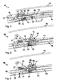
- Fig. 1 shows a front portion of a generally designated 10 adjusting device for a sunroof cover 12 on a motor vehicle.
- the sliding direction of the lid 12, at the same time vehicle longitudinal direction, is indicated in the figure by an arrow x.
- the adjusting device 10 comprises (on each cover side) a vehicle-fixed guide rail 14 running in the longitudinal direction x for guiding a (front) first slider 16 and a (rear) second slider 18.
- the sliders 16, 18 serve to control all movements of the sliding roof cover 12, which in the in Fig. 1 illustrated situation closes a roof opening (roof opening) of the motor vehicle roof, not shown. In this closed position, the cover 12 is arranged approximately flush with the (not shown) vehicle roof contour.
- the lid 12 can first be raised (ventilation position) and then backwards (in Fig. 1 to the right) are moved over a fixed roof skin section.
- the cover 12 is connected on both sides in each case via two deployment levers which are each articulated on the vehicle side in the region of the guide rail 14.
- the front of these two release levers is in Fig. 1 to recognize and denoted by 20.
- a second, further back (in Fig. 1 further right) arranged release lever is in the in Fig. 1 not shown area.
- the first slider 16 is designed as a sliding carriage, which can be moved along the guide rail 14 in the direction x in a manner known per se by a pressure-resistant drive cable running in a channel of the guide rail 14.
- This state is considered a first intermediate position in Fig. 2 shown.
- the issue of the deployment lever 20 as a result of the movement of the first slider 16 is accomplished by running three laterally protruding from the release lever 20 sliders in three different guideways.
- a front slider 22 of the lever 20 runs in a slot 24 of the first slider 16
- a middle slider 26 of the lever 20 runs in a slide 28 of the guide rail 14
- a rear slider 30 of the lever 20 runs in a guide channel 32 of the guide rail fourteenth
- Fig. 3 shows a second intermediate position of the movement of the slider 16 to the rear.
- the entrainment coupling required for this purpose is accomplished by the engagement of a laterally projecting on the first slider 16 control pin 34 in a sloping portion of a control link 36 which is formed on the second slider 18.
- the control pin 34 presses the link 36 and thus the second slider 18 in synchronism with the movement of the first slider 16 to the rear.
- the control pin 34 in this case can not be moved relative to the guide slot 36 (obliquely downwards), since the gate area 36 of the second slider 18 is fixed in this movement phase in its height with respect to the guide rail 14.
- This determination is realized by a in the figures designated 38 locking contour (locking element) which projects laterally from the second slider 18 and in the guide channel 32 of the guide rail 14 runs.
- the guide channel 32 is bounded at the top by a guide rail web 40 (one of a plurality of such webs of the guide rail). Only when the coupled to take along sliders 16, 18, the in Fig. 3 have reached the position shown, the control pin 34 can move in the control link 36, since in this position, the locking contour 38 engages in a recess 42 of the guide rail 14 upwards.
- the in the Fig. 1 to 3 apparent part of the second slider 18 is formed as a pivotable "locking lever" (with the locking contour 38 at its free end), wherein the pivot axis is not shown in the figures and approximately at the right edge of Fig. 1 runs in the transverse direction. A corresponding pivot bearing of the second slider 18 is displaceably guided in the direction x by the guide rail 14.
- the locking mechanism is essentially formed by a rotary bolt 44 mounted on the second slider 18 and rotatable about a vertical axis. It is essential here that the rotary latch 44 when leaving the second slider 18, after the height adjustment of the illustrated portion of the second slider 18, is rotated in a locking position locking the locking. This rotation is realized in the illustrated embodiment by an action of the control pin 34 on one of two radially projecting from the rotary latch 44 control cam 46, 48.
- Fig. 4 is a perspective view (from the inside) in which it is clear how the control pin 34 of the driven slider 16 engages in the control link 36 of the second slider 18.
- Fig. 4 illustrated situation corresponds to in Fig. 3 illustrated situation (second intermediate position).
- FIGS. 5 and 6 show in perspective or in a section a third intermediate position in the movement sequence, in which the control bolt 34 starts against the first control cam 46.
- Fig. 5 only the control pin 34 is drawn from the first slider 16.
- the rotary latch 44 further comprises a radially projecting locking cam 50 which is provided in the axial direction offset to the control cam assembly 44, 46 and viewed in the circumferential direction approximately in the angular position of the second control cam 48.
- Fig. 9 the locking cam 50 is viewed in a region in the height direction between a surface 52 of the guide rail 14 and a control link 36 delimiting portion of the second slider 18, so that in Fig. 9 apparent, controlled by the control pin 34 height adjustment of the second slider 18 is also still ensured if in the further movement of the control pin 34, the control link 36 leaves (in Fig. 9 to the left).
- the pivoted locking cam 50 thus a simple and reliable locking of the second slider 18 is realized in the locked state.
- the 10 and 11 illustrate again in a cross-sectional view the unlocked state ( Fig. 10 ) or the locked state ( Fig. 11 ). It can be seen that the locking cam 50 is pivoted for locking in an axial clearance between the guide rail 14 and the second slider 18, the only by the previous height adjustment of the second slider 18 (in 10 and 11 to the top).
- Fig. 12 shows again in an exploded view some of the device components already described above.
- a leaf spring 54 is shown, which secures a latching connection of the rotary latch 44 on a snap-action receptacle 56 of the second slider 18 in the assembled state and on the other secures the rotary latch 44 both in its locking rotational position and its unlocking rotational position.
- the latter rotation lock is not required per se, but ensures particularly reliable that the rotary latch 44 reliably passes after actuation by the control pin 34 in one of its two Endburnwolfen and remains.
- This action of the spring 54 on the rotary latch 44 is achieved by two flats suitably arranged in the circumferential direction on the rotary bolt shaft, against which the spring 54 rests in the mounted state (cf. Fig. 6 and 8th ).
- a modification of the just described securing the rotational position of the rotary latch 44 According to this modification, a second slider 18 'is provided with a locking contour 38' and a snap-action receptacle 56 'for receiving a rotary latch of the type already described. Unlike the in Fig. 12 However, a fork-like trained projection 54 'of the second slider 18' formed in this area of plastic is additionally provided, the two “forks" rest elastically against corresponding flats on the shaft of the assembled rotary latch and thus assume the function of securing the rotational position.
Description
Die vorliegende Erfindung betrifft eine Verstellvorrichtung für einen Schiebedachdeckel an einem Fahrzeug gemäß des Oberbegriffs des Anspruchs 1.The present invention relates to an adjustment device for a sliding roof cover on a vehicle according to the preamble of claim 1.
Eine derartige Verstellvorrichtung ist beispielsweise aus der
Bei der bekannten Vorrichtung kann der Schiebedachdeckel ausgehend von einer Schließstellung um eine vordere Schwenkachse nach außen ausgestellt und sodann nach hinten verfahren werden, um eine Dachöffnung freizugeben. An beiden Seiten des Deckels, auf dessen Unterseite, ist jeweils ein Deckelhalter angeordnet, der mit zwei in Fahrzeuglängsrichtung hintereinander angeordneten, die Bewegung des Deckels steuernden Gleitern gekoppelt ist, die in einer in Fahrzeuglängsrichtung verlaufenden fahrzeugfesten Führungsschiene geführt sind. Ein erster der beiden Gleiter ist als antreibbarer Schlitten entlang der Führungsschiene bewegbar und nimmt über einen Teil seines Bewegungsbereiches einen von einem Gleitzapfen und einem Steuerhebel gebildeten zweiten Gleiter mit, wohingegen der erste Gleiter über einen anderen Teil seines Bewegungsbereiches den zweiten Gleiter in einer vorgegebenen Position entlang der Führungsschiene zurücklässt. Der Steuerhebel des zweiten Gleiters wird durch eine Kulissenkopplung zwischen den beiden Gleitern gesteuert derart verschwenkt, dass ein am Steuerhebel angeordneter Verriegelungszapfen beim Zurücklassen des zweiten Gleiters durch eine Höhenverstellung in eine Führungsschienenaussparung gebracht wird, um den zweiten Gleiter an der Führungsschiene zu arretieren.In the known device, the sunroof lid can be issued outwardly from a closed position about a front pivot axis to the outside and then moved to the rear to release a roof opening. On both sides of the lid, on its underside, a lid holder is arranged in each case, which is coupled with two arranged in the vehicle longitudinal direction one behind the other, the movement of the lid controlling sliders, which are guided in a running in the vehicle longitudinal direction vehicle-fixed guide rail. A first of the two sliders is movable as a drivable slide along the guide rail and takes over a part of its range of motion formed by a slide pin and a control lever second slider, whereas the first slider over another part of its range of motion, the second slider in a predetermined position along leaves the guide rail. The control lever of the second slider is controlled by a linkage coupling between the two sliders pivoted so that a locking pin arranged on the control lever is brought when leaving the second slider by a height adjustment in a guide rail recess to lock the second slider to the guide rail.
Die Arretierung des zweiten Gleiters wird dadurch gesichert, dass die Kulissenkopplung über den entsprechenden Teil des Bewegungsbereiches des ersten Gleiters aufrechterhalten wird.The locking of the second slider is ensured by maintaining the linkage coupling over the corresponding part of the range of motion of the first slider.
Diese Methode der Verriegelung der Arretierung besitzt den Nachteil, dass bei zurückgelassenem zweiten Gleiter eine Kulissenkopplung zwischen den beiden Gleitern aufrechterhalten werden muss, was insbesondere dann einen erhöhten konstruktiven Aufwand bedeutet, wenn nach Arretierung des zweiten Gleiters ein vergleichsweise großer Verstellweg des ersten Gleiters gewünscht ist. Unabhängig davon ist diese Art der Verriegelung der Arretierung mit ungünstigen Kraftmomenten verbunden, die beispielsweise die Leichtgängigkeit der Gleiterbewegung nachteilig beeinträchtigen können.This method of locking the detent has the disadvantage that when leaving the second slider a link coupling between the two sliders must be maintained, which in particular means an increased design effort if after locking the second slider a comparatively large adjustment of the first slider is desired. Regardless, this type of locking the lock with unfavorable Connected to power moments that can adversely affect, for example, the ease of sliding movement.
Ähnliche Verstellvorrichtungen sind beispielsweise aus der
Auch bei diesen bekannten Vorrichtungen wird einer von zwei in einer Führungsschiene laufenden Gleitern durch den anderen Gleiter gesteuert arretiert, wozu ein Arretierelement in eine Führungsschienenaussparung verschwenkt wird und zum Entriegeln wieder herausverschwenkt wird. Bei der erstgenannten Veröffentlichung ist das Arretierelement durch eine Feder in Verriegelungsrichtung vorbelastet, bei der zweitgenannten Veröffentlichung durch eine Feder in Entriegelungsrichtung vorbelastet.Also in these known devices one of two running in a guide rail sliders is locked controlled by the other slider, including a locking member is pivoted into a guide rail recess and is pivoted out again for unlocking. In the former publication, the locking element is biased by a spring in the locking direction, biased in the second-mentioned publication by a spring in unlocking.
Wenngleich durch solche Vorbelastungen der Verriegelungsvorgang oder der Entriegelungsvorgang vereinfacht werden kann bzw. durch eine solche Vorbelastung auch die Arretierung oder Freigabe des zweiten Gleiters (durch die Federkraft) gesichert werden kann, so halten derartige konstruktive Lösungen insbesondere auf Grund von Ermüdungserscheinungen in der Regel keinen längeren Betriebsdauern stand und es können sich Fehlfunktionen ergeben. Letzterem Problem könnte zwar durch Vorsehen einer entsprechend groß dimensionierten Feder begegnet werden. Dies führt jedoch wiederum zwangsläufig zu größeren Betätigungskräften im Betrieb der Vorrichtung, was wiederum einen erhöhten konstruktiven Aufwand im Hinblick auf die mechanische Stabilität der Vorrichtungskomponenten nach sich zieht.Although by such preloads the locking process or the unlocking process can be simplified or by such a preload, the locking or release of the second slider (by the spring force) can be secured, so keep such constructive solutions, especially due to fatigue in the rule no longer Operating life and there may be malfunctions. The latter problem could indeed be countered by providing a correspondingly large-sized spring. However, this in turn inevitably leads to larger actuation forces in the operation of the device, which in turn entails an increased design effort in terms of the mechanical stability of the device components by itself.
Zusammenfassend müssen die bekannten Mechaniken zum Arretieren und Freigeben des betreffenden Gleiters bzw. zum Sichern (Verriegeln) und Entsichern (Entriegeln) der Arretierung ungünstige Kräfte aufnehmen oder übertragen Kräfte in einer Weise auf andere Komponenten der Verstellvorrichtung, welche die Gleiterbewegungen nachteilig beeinträchtigen kann.In summary, the known mechanisms for locking and releasing the respective slider or for securing (locking) and unlocking (unlocking) the detent must absorb unfavorable forces or transmit forces in a manner to other components of the adjustment, which may adversely affect the slider movements.
Es ist daher eine Aufgabe der vorliegenden Erfindung, eine Verstellvorrichtung der eingangs genannten Art bereitzustellen, bei welcher ungünstige Kräfte im Zusammenhang mit der Arretierung und Freigabe des zweiten Gleiters vermieden werden können.It is therefore an object of the present invention to provide an adjustment device of the type mentioned, in which unfavorable forces in connection with the locking and release of the second slider can be avoided.
Diese Aufgabe wird gelöst durch eine Verstellvorrichtung mit den Merkmalen des Anspruchs 1. Die abhängigen Ansprüche betreffen vorteilhafte Weiterbildungen der Erfindung.This object is achieved by an adjusting device with the features of claim 1. The dependent claims relate to advantageous developments of the invention.
Bei der erfindungsgemäßen Verstellvorrichtung ist am zweiten Gleiter ein durch den ersten Gleiter gesteuert um eine Hochachse drehbarer Drehriegel angeordnet, welcher beim Zurücklassen des zweiten Gleiters, nach der Höhenverstellung des Arretierelements, in eine die Arretierung verriegelnde Drehstellung gedreht wird.In the adjusting device according to the invention a controlled by the first slider is rotatable about a vertical axis rotary latch arranged on the second slider, which is rotated when leaving the second slider, after the height adjustment of the locking element in a lock locking the rotary position.
Damit ist eine einfache und funktionssichere Verriegelung (und Entriegelung) der Arretierung geschaffen. Die Funktionssicherheit der erfindungsgemäßen Lösung beruht darauf, dass eine z. B. durch Vibrationen oder Stöße verursachte Kraftbeaufschlagung des Arretierelements in Hochrichtung durch den Drehriegel sicher (zur Vermeidung einer Bewegung des Arretierelements) aufgenommen werden kann und darüber hinaus den Drehriegel allenfalls parallel zu seiner Drehachse belastet, nicht jedoch ein drehendes Kraftmoment auf den Drehriegel ausübt.This creates a simple and reliable locking (and unlocking) of the lock. The reliability of the solution according to the invention is based on the fact that a z. B. caused by vibration or shock force of the locking element in the vertical direction by the rotary latch safely (to avoid movement of the locking element) can be added and beyond the rotary latch loaded at best parallel to its axis of rotation, but not a rotating moment of force exerted on the rotary latch.
Darüber hinaus kann der Drehriegel ohne weiteres in Verriegelungsdrehrichtung und/oder Entriegelungsdrehrichtung ohne nennenswerte Kraftbeaufschlagung (z. B. durch Reibkräfte) betätigbar (verschwenkbar) vorgesehen werden.In addition, the rotary latch can readily be actuated (pivotable) in the direction of locking rotation and / or unlocking direction without appreciable application of force (eg by frictional forces).
Bei bekannten Vorrichtungen direkt aus dem Arretierungsmechanismus auf die Verriegelungsmechanik eingeleitete und somit ungünstige Kräfte können bei der Erfindung vorteilhaft vermieden werden. Die bei der Sicherung der Arretierung und Freigabe wirkenden Kräfte können bei der Erfindung gewissermaßen von den bei der Betätigung des Drehriegels wirkenden Kräften "entkoppelt" werden. Die zum Sichern der Arretierung erforderlichen Gegenkräfte können vorteilhaft durch den in seine Verriegelungsdrehstellung verdrehten Drehriegel aufgenommen werden. Sie werden somit von den übrigen Komponenten der Verstellvorrichtung ferngehalten.In known devices introduced directly from the locking mechanism on the locking mechanism and thus unfavorable forces can be advantageously avoided in the invention. The forces acting in securing the locking and releasing forces can in a sense be "decoupled" in the invention by the forces acting on the rotary latch. The counter-forces required to secure the lock can be advantageously absorbed by the rotated in his locking rotational position rotary latch. They are thus kept away from the other components of the adjustment.
Eine bevorzugte Anwendung der Erfindung ist die Verstellung eines Schiebedachdeckels, der in einer Schließstellung eine Dachöffnung verschließt, in eine Ausstelllage ("Lüftungsstellung") hochschwenkbar ist und dann zurückgeschoben werden kann. Dies ist z. B. der Fall bei so genannten Spoilerdächern oder außen laufenden Schiebedächern. Die Verstellvorrichtung ist jedoch gleichermaßen z. B. für Schiebedächer geeignet, bei denen der Deckel ausgehend von der Schließstellung alternativ oder zusätzlich zur Hochschwenkung abgesenkt und dann zurückgeschoben werden kann. Für die Erfindung wesentlich ist in diesem Zusammenhang lediglich, dass zwei entlang einer Führungsschiene bewegbare Gleiter zur Steuerung der (an sich beliebig gestaltbaren) Schiebedachdeckelbewegung vorgesehen sind und eine Mitnahmekopplung zwischen den Gleitern lediglich über einen Teil des Bewegungsbereiches des einen der beiden Gleiter ("erster Gleiter") besteht.A preferred application of the invention is the adjustment of a sunroof cover, which closes a roof opening in a closed position, can be swung up into an open position ("ventilation position") and can then be pushed back. This is z. As is the case with so-called spoiler roofs or outside sliding roofs. However, the adjustment is equally z. B. suitable for sunroofs, in which the lid lowered starting from the closed position alternatively or in addition to Hochschwenkung and then be pushed back. For the invention is essential in this context only that two along a guide rail movable slider for controlling the (in any designable) sliding roof cover movement are provided and a driving coupling between the sliders only over part of the range of motion of the two sliders ("first slider ") consists.
Die Längsrichtung, in welcher sich die fahrzeugfeste Führungsschiene erstreckt, ist die "Schieberichtung" des Schiebedachdeckels. Üblicherweise ist diese Längsrichtung identisch mit der Längsrichtung des betreffenden Fahrzeugs.The longitudinal direction in which the vehicle-fixed guide rail extends is the "sliding direction" of the sliding roof cover. Usually, this longitudinal direction is identical to the longitudinal direction of the vehicle in question.
In an sich bekannter Weise kann wenigstens einer der beiden Gleiter zumindest mittelbar mit dem Schiebedachdeckel oder einem den Deckel tragenden Deckelträger verbunden sein. Der Deckel bzw. Deckelträger kann z. B. durch Ausstellhebel, Hubkulissen etc. mit den Gleitern verbunden sein.In a manner known per se, at least one of the two sliders can be connected at least indirectly to the sliding roof cover or to a cover carrier carrying the cover. The lid or lid carrier may, for. B. by Ausstellhebel, Hubkulissen etc. be connected to the gliders.
Die den ersten Gleiter entlang der Führungsschiene bewegende Antriebseinrichtung kann in an sich bekannter Weise z. B. ein in Mitnahmeverbindung zu dem ersten Gleiter stehendes, drucksteifes Antriebskabel umfassen, welches an oder in der Führungsschiene in Längsrichtung verlaufend geführt ist.The first slider along the guide rail moving drive device can in a conventional manner z. B. include a driving connection to the first slider standing, pressure-rigid drive cable, which is guided on or in the guide rail extending in the longitudinal direction.
In einer bevorzugten Ausführungsform weist der Drehriegel eine radial abstehende Riegelnocke auf, die zum Verriegeln in einen durch die Höhenverstellung geschaffenen Freiraum zwischen einem mit dem Arretierelement verbundenen Abschnitt des zweiten Gleiters und einem Abschnitt der Führungsschiene schwenkt. Bevorzugt ist dieser Freiraum bzw. die dort hinein schwenkende Riegelnocke hierbei so bemessen, dass die Verschwenkung im Wesentlichen ohne nennenswerte Kraftbeaufschlagung (z. B. durch Reibungskräfte) erfolgt. Dasselbe gilt für das Herausschwenken der Riegelnocke aus dem Freiraum im Falle der Entriegelung der Arretierung. Bevorzugt wird die Riegelnocke in Axialrichtung (Hochrichtung) von zwei im Wesentlichen orthogonal zur Axialrichtung sich erstreckenden Riegelnockenflächen begrenzt, an denen im verriegelten Zustand einerseits der betreffende Abschnitt des zweiten Gleiters und andererseits der betreffende Abschnitt der Führungsschiene (bevorzugt ebenfalls mit horizontalen Anschlagflächen) anliegen.In a preferred embodiment, the rotary latch on a radially projecting locking cam, which pivots for locking in a space created by the height adjustment clearance between a connected to the locking member portion of the second slider and a portion of the guide rail. In this case, this free space or the locking cam pivoting into it is preferably dimensioned so that the pivoting takes place substantially without appreciable application of force (for example due to frictional forces). The same applies to the swinging out of the locking cam from the free space in the case of unlocking the lock. The locking cam is preferably bounded in the axial direction (vertical direction) by two locking cam surfaces extending substantially orthogonally to the axial direction, against which the relevant section of the second slider and on the other hand the relevant section of the guide rail (preferably likewise with horizontal stop surfaces) abut in the locked state.
Für eine konstruktiv einfache Ansteuerung der Drehung des Drehriegels ist es von Vorteil, wenn der Drehriegel zwei radial abstehende, zueinander winkelversetzte Steuernocken aufweist, mit denen ein seitlich abstehender Steuerbolzen des ersten Gleiters zum Drehen des Drehriegels zusammenwirkt. Für eine kompakte Bauform ist es hierbei wiederum von Vorteil, wenn die beiden Steuernocken auf axial gleicher Höhe am Drehriegel angeordnet sind. Falls hierbei die oben erwähnte Riegelnocke vorgesehen ist, so ist diese bevorzugt axial versetzt zu den beiden Steuernocken am Drehriegel angeordnet.For a structurally simple control of the rotation of the rotary latch, it is advantageous if the rotary latch two radially projecting, mutually angularly offset Control cam having a laterally projecting control pin of the first slider cooperates to rotate the rotary latch. For a compact design, it is again advantageous if the two control cams are arranged at the same height on the rotary latch. If in this case the above-mentioned locking cam is provided, then this is preferably arranged axially offset from the two control cams on the rotary latch.
In einer bevorzugten Ausführungsform ist der Drehriegel als Kunststoffformteil (z. B. Spritzgussteil) gefertigt. Dies ist insofern unproblematisch, als diese Komponente bei deren Betätigung (Drehung) nicht nennenswert belastet werden muss und die "Verriegelungskraft" den Drehriegel lediglich auf axialen Druck belastet.In a preferred embodiment, the rotary latch is produced as a plastic molded part (eg injection molded part). This is unproblematic insofar as this component does not have to be significantly stressed during its actuation (rotation) and the "locking force" merely loads the rotary latch on axial pressure.
Der oben erwähnte Steuerbolzen des ersten Gleiters kann neben der Betätigung des Drehriegels bei der erfindungsgemäßen Verstellvorrichtung weitere Funktionen besitzen. So ist gemäß einer Weiterbildung vorgesehen, dass der Steuerbolzen des ersten Gleiters mit einer Kulissenbahn eines mit dem Arretierelement verbundenen Abschnitts des zweiten Gleiters zusammenwirkt, um die Höhenverstellung zu bewirken. Wenn an wenigstens einem Ende einer solchen Kulissenbahn ein Anschlag für den Steuerbolzen vorgesehen ist, so kann der Steuerbolzen darüber hinaus vermittels dieses Anschlags die Mitnahmekopplung zwischen den beiden Gleitern bewirken.The above-mentioned control pin of the first slider may have other functions in addition to the operation of the rotary latch in the adjusting device according to the invention. Thus, according to a further development, the control bolt of the first slider interacts with a slide track of a portion of the second slider connected to the locking element in order to effect the height adjustment. If a stop for the control pin is provided on at least one end of such a slide track, so the control bolt can also cause by means of this stop the driving coupling between the two sliders.
In einer Ausführungsform der Erfindung ist vorgesehen, dass der Drehriegel in seiner Verriegelungsdrehstellung und/oder seiner Entriegelungsdrehstellung durch eine Federbelastung gesichert ist. Erwähnenswert ist in diesem Zusammenhang, dass eine solche Federbelastung im Gegensatz zu den eingangs mit Bezug auf den Stand der Technik erwähnten Federbelastungen vorteilhaft äußerst gering bemessen sein kann, da sämtliche im Betrieb im Sinne einer Drehung des Drehriegels auf diesen wirkende Kräfte sehr klein vorgesehen sein können.In one embodiment of the invention it is provided that the rotary latch is secured in its locking rotational position and / or its unlocking rotational position by a spring load. It is worth noting in this context that such a spring load, in contrast to the spring loads mentioned at the outset with reference to the prior art may advantageously be extremely small, since all forces acting on these in operation in terms of rotation of the rotary latch can be provided very small ,
In einer Ausführungsform ist vorgesehen, dass der erste Gleiter nach dem Zurücklassen des zweiten Gleiters vollständig vom zweiten Gleiter entkoppelt wird. Wenn der erste Gleiter z. B. über eine Kulissenkopplung mit dem zweiten Gleiter gekoppelt ist, so kann die vollständige Entkoppelbarkeit dadurch vorgesehen sein, dass die betreffende Kulissenbahn an einem Ende "offen" ist, so dass an dieser Stelle eine Entkopplung erfolgen kann und der erste Gleiter bei zurückgelassenem zweiten Gleiter im Prinzip beliebig weit bewegt werden kann.In one embodiment, it is provided that the first slider is completely decoupled from the second slider after leaving the second slider. If the first slider z. B. coupled via a link coupling with the second slider, so the complete Entkoppelbarkeit be provided that the relevant slide track is "open" at one end, so that at this point decoupling can be done and the first slider left behind second slider in principle, can be moved arbitrarily far.
In einer vorteilhaften Ausführungsform ist vorgesehen, dass der erste Gleiter mit einem seitlich abstehenden Steuerbolzen in einer einseitig offenen Kulissenbahn (z. B. Kulissenschlitz) läuft, die am zweiten Gleiter, insbesondere an einem Abschnitt des zweiten Gleiters vorgesehen ist, der mit dem höhenverstellbaren Arretierelement verbunden ist.In an advantageous embodiment, it is provided that the first slider with a laterally projecting control bolt runs in a slide track (eg slide slot) open on one side, which is provided on the second slider, in particular on a section of the second slider, with the height-adjustable locking element connected is.
In einer Ausführungsform ist das Arretierelement an einem um eine Querachse verschwenkbaren Arretierhebel des zweiten Gleiters angeordnet. Die Höhenverstellung des Arretierelements kann dann durch eine Verschwenkung des Arretierhebels bewirkt werden, wobei für eine große Höhenverstellung bei vorgegebenem Verschwenkwinkel die Anordnung des Arretierelements im Bereich des freien Endes des Arretierhebels bevorzugt ist.In one embodiment, the locking element is arranged on a pivotable about a transverse axis locking lever of the second slider. The height adjustment of the locking element can then be effected by pivoting the locking lever, wherein the arrangement of the locking element in the region of the free end of the locking lever is preferred for a large height adjustment at a predetermined pivoting angle.
In einer bevorzugten Ausführungsform ist vorgesehen, dass das Arretierelement seitlich vom zweiten Gleiter absteht und während der Mitnahme des zweiten Gleiters in einem durch einen horizontalen Führungsschienensteg begrenzten Führungskanal der Führungsschiene läuft und bei Erreichen der vorbestimmten Position durch die Höhenverstellung in eine Aussparung des Führungsschienenstegs eindringt.In a preferred embodiment it is provided that the locking element protrudes laterally from the second slider and during the entrainment of the second slider in a limited by a horizontal guide rail web guide channel of the guide rail and penetrates upon reaching the predetermined position by the height adjustment in a recess of the guide rail web.
Die Erfindung wird nachfolgend anhand eines Ausführungsbeispiels mit Bezug auf die beigefügten Zeichnungen näher erläutert. Es stellen dar:
- Fig. 1
- eine Seitenansicht einer Verstellvorrichtung für einen Schiebedach- deckel, wobei die Situation für die Schließstellung des Deckels dargestellt ist,
- Fig. 2
- eine Seitenansicht ähnlich
Fig. 1 , jedoch für eine erste Zwischen- stellung (im Verlauf eines Dachöffnungsvorganges), - Fig. 3
- eine Seitenansicht ähnlich
Fig. 1 , jedoch für eine zweite Zwischen- stellung, - Fig. 4
- eine perspektivische Ansicht der Situation gemäß
Fig. 3 , - Fig. 5
- eine perspektivische Ansicht ähnlich
Fig. 4 , jedoch für eine dritte Zwischenstellung, - Fig. 6
- eine horizontale Schnittansicht längs der Linie VI-VI in
Fig. 5 , - Fig. 7
- eine perspektivische Ansicht ähnlich der
Fig. 5 , jedoch für eine vierte Zwischenstellung, - Fig. 8
- eine der
Fig..6 entsprechende Schnittansicht, jedoch für eine fünfte Zwischenstellung, - Fig. 9
- eine perspektivische Ansicht ähnlich
Fig. 5 , jedoch für die fünfte Zwischenstellung, - Fig.10
- eine Querschnittsansicht zur Veranschaulichung des entriegelten Zustands der Gleiterarretierung, wie er z. B. in den Situationen gemäß der
Fig. 1 bis 6 vorliegt, - Fig. 11
- eine Querschnittsansicht ähnlich
Fig. 10 , jedoch für den verriegelten Zustand der Gleiterarretierung, wie er z. B. für die Situationen gemäß derFig. 8 und 9 vorliegt, - Fig. 12
- eine Explosionsdarstellung einiger für die Verriegelungsmechanik wesentlicher Vorrichtungskomponenten, und
- Fig. 13
- eine perspektivische Darstellung zur Veranschaulichung einer Ab- wandlung der in
Fig. 12 gezeigten Mechanik.
- Fig. 1
- a side view of an adjustment device for a sliding roof cover, wherein the situation for the closed position of the lid is shown,
- Fig. 2
- a side view similar
Fig. 1 , but for a first intermediate position (in the course of a roof opening process), - Fig. 3
- a side view similar
Fig. 1 but for a second intermediate position, - Fig. 4
- a perspective view of the situation according to
Fig. 3 . - Fig. 5
- a perspective view similar
Fig. 4 , but for a third intermediate position, - Fig. 6
- a horizontal sectional view taken along the line VI-VI in
Fig. 5 . - Fig. 7
- a perspective view similar to the
Fig. 5 , but for a fourth intermediate position, - Fig. 8
- one of the
Fig..6 corresponding sectional view, but for a fifth intermediate position, - Fig. 9
- a perspective view similar
Fig. 5 , but for the fifth intermediate position, - Figure 10
- a cross-sectional view illustrating the unlocked state of the slider lock, as z. B. in the situations according to the
Fig. 1 to 6 is present, - Fig. 11
- a cross-sectional view similar
Fig. 10 , However, for the locked state of the slider lock, as z. B. for the situations according to the8 and 9 is present, - Fig. 12
- an exploded view of some essential for the locking mechanism device components, and
- Fig. 13
- a perspective view illustrating a modification of the in
Fig. 12 shown mechanics.
Dargestellt und nachfolgend beschrieben sind der Einfachheit der Darstellung halber lediglich auf einer Seite des Deckels 12 angeordnete Vorrichtungskomponenten, die in an sich bekannter Weise tatsächlich an beiden Deckelseiten vorhanden sind.Shown and described below are the sake of simplicity of illustration only arranged on one side of the
Die Verstellvorrichtung 10 umfasst (auf jeder Deckelseite) eine in Längsrichtung x verlaufende fahrzeugfeste Führungsschiene 14 zur Führung eines (vorderen) ersten Gleiters 16 und eines (hinteren) zweiten Gleiters 18.The adjusting
Die Gleiter 16, 18 dienen zur Steuerung sämtlicher Bewegungen des Schiebedachdeckels 12, der in der in
Ausgehend von der Schließstellung kann der Deckel 12 zunächst angehoben werden (Lüftungsstellung) und sodann nach hinten (in
Der erste Gleiter 16 ist als ein Gleitschlitten ausgebildet, der in an sich bekannter Weise durch ein daran angreifendes, in einem Kanal der Führungsschiene 14 laufendes drucksteifes Antriebskabel entlang der Führungsschiene 14 in Richtung x verfahrbar ist.The
Wenn dieser erste Gleiter 16 ausgehend von seiner in
Dieser Zustand ist als eine erste Zwischenstellung in
Die Art und Weise, wie die Ausstellbewegung des Deckels 12 bewirkt wird, ist nicht Gegenstand der vorliegenden Erfindung und könnte daher auch in beliebig anderer geeigneter Weise vorgesehen sein.The manner in which the raising movement of the
Im dargestellten Ausführungsbeispiel wird das Ausstellen des Ausstellhebels 20 infolge der Bewegung des ersten Gleiters 16 dadurch bewerkstelligt, dass drei seitlich vom Ausstellhebel 20 abstehende Gleitstücke in drei verschiedenen Führungsbahnen laufen. Ein vorderes Gleitstück 22 der Hebels 20 läuft in einer Kulisse 24 des ersten Gleiters 16, ein mittleres Gleitstück 26 des Hebels 20 läuft in einer Kulisse 28 der Führungsschiene 14, und ein hinteres Gleitstück 30 des Hebels 20 läuft in einem Führungskanal 32 der Führungsschiene 14.In the illustrated embodiment, the issue of the
Über den in den
Die hierfür erforderliche Mitnahmekopplung ist durch den Eingriff eines seitlich am ersten Gleiter 16 abstehenden Steuerbolzens 34 in einen schräg verlaufenden Abschnitt einer Steuerkulisse 36 bewerkstelligt, die am zweiten Gleiter 18 ausgebildet ist.The entrainment coupling required for this purpose is accomplished by the engagement of a laterally projecting on the
Bei der Bewegung des ersten Gleiters und somit des Steuerbolzens 34 drückt der Steuerbolzen 34 die Kulisse 36 und somit den zweiten Gleiter 18 synchron zur Bewegung des ersten Gleiters 16 nach hinten. In einem ersten Teil dieses Bewegungsablaufs (vgl.
Wenngleich beim Übergang von
Mit dem Erreichen der in
Bei der weiteren Bewegung des ersten Gleiters 16 nach hinten wird nun der zweite Gleiter 18 in seiner durch die Aussparung 42 vorgegebenen Position zurückgelassen. Dieser Teil des Bewegungsbereiches des ersten Gleiters 16 ist für die Verschiebung des Schiebedachdeckels 12 nach hinten über die feste Dachhaut vorgesehen. Solange sich bei dieser weiteren Bewegung der Steuerbolzen 34 noch im Eingriff mit der Steuerkulisse 36 des zweiten Gleiters 18 befindet, ist die höhenmäßige Position des dargestellten Abschnitts des Gleiters 18 und somit die Arretierung des Gleiters 18 sichergestellt.In the further movement of the
Da der Steuerbolzen 34 jedoch bei der weiteren Bewegung die in Richtung x relativ kurz bemessene Steuerkulisse 36 verlässt, wird bei der Verstellvorrichtung 10 unmittelbar vor diesem Verlassen die höhenmäßige Festlegung des zweiten Gleiters 18 und somit die Arretierung des Gleiters 18 durch einen besonderen Verriegelungsmechanismus gesichert.However, since the
Der Verriegelungsmechanismus ist im Wesentlichen von einem am zweiten Gleiter 18 gelagerten, um eine Hochachse drehbaren Drehriegel 44 gebildet. Wesentlich ist hierbei, dass der Drehriegel 44 beim Zurücklassen des zweiten Gleiters 18, nach der Höhenverstellung des dargestellten Abschnitts des zweiten Gleiters 18, in eine die Arretierung verriegelnde Drehstellung gedreht wird. Diese Verdrehung wird im dargestellten Ausführungsbeispiel durch eine Einwirkung des Steuerbolzens 34 auf eine von zwei radial vom Drehriegel 44 abstehenden Steuernocken 46, 48 realisiert.The locking mechanism is essentially formed by a
Diese zum Verriegeln (und Entriegeln) vorgesehene Mechanik ist aus den nachfolgend beschriebenen Figuren besser ersichtlich.This mechanism provided for locking (and unlocking) is better understood from the figures described below.
Ferner erkennt man in
Die
Im weiteren Bewegungsablauf weicht nun die Steuernocke 46 dem dagegen anlaufenden Steuerbolzen 34 aus, so dass der Drehriegel 44 (in
Es ergibt sich eine vierte Zwischenstellung, die in
Bei Erreichen der in
Wie es aus den
In
Bemerkenswert ist hierbei zum einen, dass die zum Verriegeln notwendige Drehung des Drehriegels 44 ohne nennenswerten Kraftaufwand mittels des Steuerbolzens 34 bewerkstelligt werden kann und dass jegliche im Betrieb, insbesondere während der Fahrt des betreffenden Fahrzeugs, auftretende Kräfte, die den zweiten Gleiter 18 nach unten zu drücken versuchen, zuverlässig von der Riegelnocke 50 aufgenommen werden, die sich wiederum an der Führungsschiene 14 abstützt. Solche Kräfte werden darüber hinaus vorteilhaft von den übrigen Komponenten der Verstellvorrichtung 10 ferngehalten.It is noteworthy here, on the one hand, that the rotation of the
Die
Der oben beschriebene Bewegungsablauf findet in umgekehrter Reihenfolge beim Schließen des Schiebedachdeckels 12 statt.The movement described above takes place in reverse order when closing the
Was den in diesem umgekehrten Bewegungsablauf stattfindenden Entriegelungsvorgang anbelangt, so ist beispielsweise aus
- 1010
- Verstellvorrichtungadjustment
- 1212
- Schiebedachdeckelsunroof cover
- 1414
- Führungsschieneguide rail
- 1616
- erster Gleiter (Antriebsschlitten)first slider (drive slide)
- 1818
- zweiter Gleitersecond glider
- 2020
- Ausstellhebelout lever
- 2222
- Gleitstückslide
- 2424
- Kulissescenery
- 2626
- Gleitstückslide
- 2828
- Kulissescenery
- 3030
- Gleitstückslide
- 3232
- Führungskanal (Kulisse)Guide channel (backdrop)
- 3434
- Steuerbolzencontrol bolt
- 3636
- Steuerkulissecontrol link
- 3838
- Riegelkonturlatching contour
- 4040
- FührungsschienenstegGuide rail web
- 4242
- FührungsschienenaussparungGuide rail recess
- 4444
- DrehriegelSpagnolet
- 4646
- erste Steuernockefirst control cam
- 4848
- zweite Steuernockesecond control cam
- 5050
- Riegelnockelatch cam
- 5252
- FührungsschienenflächeGuide rail surface
- 5454
- Federfeather
- 5656
- Schnappaufnahmesnap recording
Claims (8)
- Adjustment device for a sliding roof cover (12) on a vehicle, comprising a guide rail (14) which runs in the longitudinal direction (x), is mounted on the vehicle and is intended for guiding first and second sliders (16, 18) which are arranged consecutively in the longitudinal direction (x) and control the movement of the sliding roof cover (12),
wherein the first slider (16) can be moved along the guide rail (14) by means of a drive device and, over part of its movement range, carries along the second slider (18) and, over another part of its movement range, leaves the second slider behind in a predetermined position along the guide rail (14),
wherein an arresting element (38) which can be adjusted in height in a manner controlled by the first slider (16) is arranged on the second slider (18) and, when the second slider (18) is left behind, is brought by means of a height adjustment into a form-fitting connection with a guide rail section (42) in order to arrest the second slider (18) on the guide rail (14),
characterized in that a rotary latch (44) which can be rotated about a vertical axis in a manner controlled by the first slider (16) is furthermore arranged on the second slider (18) and, when the second slider (18) is left behind, and after the height adjustment of the arresting element (38), is rotated into a rotary position locking the arresting action. - Adjustment device according to Claim 1, wherein the rotary latch (44) has a radially protruding latching cam (50) which, for locking purposes, pivots into a clearance, which is created by the height adjustment, between a section of the second slider (18), which section is connected to the arresting element (38), and a section (52) of the guide rail (14).
- Adjustment device according to one of the preceding claims, wherein the rotary latch (44) has two control cams (46, 48) which protrude radially, are offset in angle with respect to each other and with which a laterally protruding control bolt (34) of the first slider (16) interacts in order to rotate the rotary latch (44).
- Adjustment device according to Claim 3, wherein the control bolt (34) of the first slider (16) interacts with a slotted guide track (36) of a section of the second slider (18), which section is connected to the arresting element (38), in order to bring about the height adjustment.
- Adjustment device according to one of the preceding claims, wherein the rotary latch (44) is secured in its locking rotary position and/or in its unlocking rotary position by means of spring loading (54, 54').
- Adjustment device according to one of the preceding claims, wherein, after the second slider (18) is left behind, the first slider (16) is completely decoupled from the second slider (18).
- Adjustment device according to one of the preceding claims, wherein the arresting element (38) is arranged on an arresting lever, which can be pivoted about a transverse axis, of the second slider (18).
- Adjustment device according to one of the preceding claims, wherein the arresting element (38) protrudes laterally from the second slider (18) and, during the carrying-along of the second slider (18), runs in a guide channel of the guide rail, which guide channel is bounded by a horizontal guide rail web (40), and, when the predetermined position is reached, penetrates by means of the height adjustment into a cutout (42) of the guide rail web (40).
Applications Claiming Priority (2)
| Application Number | Priority Date | Filing Date | Title |
|---|---|---|---|
| DE102006010755A DE102006010755B4 (en) | 2006-03-08 | 2006-03-08 | Adjustment device for a sliding roof cover on a vehicle |
| PCT/DE2007/000366 WO2007101425A1 (en) | 2006-03-08 | 2007-02-27 | Adjustment device for a sliding roof cover on a vehicle |
Publications (2)
| Publication Number | Publication Date |
|---|---|
| EP1991436A1 EP1991436A1 (en) | 2008-11-19 |
| EP1991436B1 true EP1991436B1 (en) | 2010-06-23 |
Family
ID=38132538
Family Applications (1)
| Application Number | Title | Priority Date | Filing Date |
|---|---|---|---|
| EP07721967A Not-in-force EP1991436B1 (en) | 2006-03-08 | 2007-02-27 | Adjustment device for a sliding roof cover on a vehicle |
Country Status (6)
| Country | Link |
|---|---|
| US (1) | US20090079234A1 (en) |
| EP (1) | EP1991436B1 (en) |
| JP (1) | JP4836012B2 (en) |
| CN (1) | CN101400532B (en) |
| DE (2) | DE102006010755B4 (en) |
| WO (1) | WO2007101425A1 (en) |
Families Citing this family (13)
| Publication number | Priority date | Publication date | Assignee | Title |
|---|---|---|---|---|
| DE102011102890A1 (en) * | 2011-05-31 | 2012-12-06 | GM Global Technology Operations LLC (n. d. Gesetzen des Staates Delaware) | Shading system, motor vehicle and method for this |
| DE102012016504C5 (en) * | 2012-08-20 | 2018-01-04 | Roof Systems Germany Gmbh | sliding roof system |
| DE102013005217B4 (en) * | 2013-03-27 | 2019-03-14 | Webasto SE | Vehicle sunroof device with two adjustable lids |
| DE102014110626A1 (en) | 2014-05-14 | 2015-11-19 | Webasto SE | Arrangement with a cover for a vehicle roof |
| DE102016203131A1 (en) * | 2016-02-26 | 2017-08-31 | Bos Gmbh & Co. Kg | Drive system for a movable roof part of a roof module of a motor vehicle |
| CA2991735C (en) | 2016-07-27 | 2020-04-28 | Scott Williamson | Tonneau cover system for a cargo bed of a vehicle |
| US9821643B1 (en) * | 2016-10-26 | 2017-11-21 | AISIN Technical Center of America, Inc. | Guide block for sunroof of an automobile |
| US10286765B2 (en) | 2016-10-28 | 2019-05-14 | Rugged Liner, Inc. | Tonneau cover system for a cargo bed of a vehicle |
| DE102017202127A1 (en) | 2017-02-10 | 2018-08-16 | Bos Gmbh & Co. Kg | Sunroof system for a motor vehicle |
| CN107953760B (en) * | 2017-11-23 | 2019-07-05 | 杭州科技职业技术学院 | Automobile skylight device |
| DE102018104610A1 (en) * | 2018-02-28 | 2019-08-29 | Webasto SE | Arrangement for a vehicle roof, vehicle roof for a motor vehicle and motor vehicle |
| US10960741B2 (en) | 2019-03-18 | 2021-03-30 | AISIN Technical Center of America, Inc. | Rotating lock having notch for sunroof check systems |
| DE102019113142A1 (en) * | 2019-05-17 | 2020-11-19 | Webasto SE | Arrangement and method for moving a lid |
Family Cites Families (11)
| Publication number | Priority date | Publication date | Assignee | Title |
|---|---|---|---|---|
| FR2601303B1 (en) * | 1986-07-12 | 1992-02-14 | Webasto Werk Baier Kg W | MANEUVERING DEVICE FOR AN OPENING ROOF OF A VEHICLE IN WHICH THE OPERATION LEVER IS CONNECTED WITH THE FIRST SLIDING ELEMENT. |
| DE3715268A1 (en) * | 1986-07-12 | 1988-01-21 | Webasto Werk Baier Kg W | Operating device for a vehicle roof |
| DE4320106C2 (en) * | 1993-06-17 | 1997-08-14 | Hs Products Ag Systemtechnik U | Device for controlling the movement of a vehicle sunroof cover |
| DE19944853C5 (en) * | 1999-09-18 | 2007-02-22 | Magna Car Top Systems Gmbh | Drive device for in a predetermined sequence mutually adjustable parts, in particular roof and / or cover parts of motor vehicles |
| DE10009387C5 (en) * | 2000-02-29 | 2007-08-02 | Webasto S.P.A., Venaria | Device for controlling the movement of a vehicle sliding roof cover |
| JP4389362B2 (en) * | 2000-06-28 | 2009-12-24 | 株式会社豊田自動織機 | Tilt-type sunroof for vehicles |
| DE10039150C1 (en) * | 2000-08-05 | 2002-01-10 | Webasto Vehicle Sys Int Gmbh | Device, to couple slide on guide rail to carrier, engages carrier when it reaches first locking position on slide and uncouples carrier after further movement into second locking position |
| DE10063055B4 (en) * | 2000-12-18 | 2005-04-07 | Webasto Ag | Vehicle roof with two adjustable lids |
| DE10217147C1 (en) * | 2002-04-17 | 2003-10-16 | Webasto Vehicle Sys Int Gmbh | Wind deflector for an open automobile roof, where the roof elements slide along side guide rails, has a drive at the rear of the rails with couplings to push the deflector and the roof elements into position when opening the roof |
| FR2842764B1 (en) * | 2002-07-26 | 2006-02-03 | Webasto Systemes Carrosserie | MOTOR VEHICLE PAVILION CONFIGURATION DEVICE COMPRISING A CURTAIN AND A MUSIC SLIDING PANEL BY A SINGLE ENGINE |
| DE102004027728B4 (en) * | 2004-02-20 | 2014-02-06 | Michael Heidan | Detent coupling mechanism for a sunroof |
-
2006
- 2006-03-08 DE DE102006010755A patent/DE102006010755B4/en not_active Expired - Fee Related
-
2007
- 2007-02-27 EP EP07721967A patent/EP1991436B1/en not_active Not-in-force
- 2007-02-27 US US12/162,387 patent/US20090079234A1/en not_active Abandoned
- 2007-02-27 CN CN2007800082476A patent/CN101400532B/en active Active
- 2007-02-27 JP JP2008557585A patent/JP4836012B2/en not_active Expired - Fee Related
- 2007-02-27 DE DE502007004189T patent/DE502007004189D1/en active Active
- 2007-02-27 WO PCT/DE2007/000366 patent/WO2007101425A1/en active Application Filing
Also Published As
| Publication number | Publication date |
|---|---|
| US20090079234A1 (en) | 2009-03-26 |
| CN101400532A (en) | 2009-04-01 |
| CN101400532B (en) | 2010-08-04 |
| EP1991436A1 (en) | 2008-11-19 |
| JP2009528942A (en) | 2009-08-13 |
| DE102006010755A1 (en) | 2007-09-13 |
| DE102006010755B4 (en) | 2008-02-28 |
| DE502007004189D1 (en) | 2010-08-05 |
| WO2007101425A1 (en) | 2007-09-13 |
| JP4836012B2 (en) | 2011-12-14 |
Similar Documents
| Publication | Publication Date | Title |
|---|---|---|
| EP1991436B1 (en) | Adjustment device for a sliding roof cover on a vehicle | |
| EP1561620B1 (en) | Mechanism for a sliding roof | |
| DE3715268C2 (en) | ||
| EP1767388A2 (en) | Pivotable sliding vehicle door , especially for public transport | |
| DE3442631A1 (en) | SLIDING LIFTING ROOF | |
| EP1809503B1 (en) | Sunroof device for motor vehicles | |
| EP1072456B1 (en) | Tensioning and locking device for releasibly fixing a vehicle roof to a vehicle body part | |
| EP1922220B1 (en) | Vehicle roof with at least two cover elements | |
| DE10057872B4 (en) | Hardtop vehicle roof | |
| EP2096027B1 (en) | Flap control | |
| DE102018130016A1 (en) | Sunroof system for a motor vehicle | |
| WO2006039881A1 (en) | Cabriolet-vehicle | |
| DE10237492B3 (en) | Device for opening and / or closing a wing relative to a frame stick | |
| DE102010018867A1 (en) | Vehicle roof comprises rear cover and front cover which is adjusted at its rear edge, where control mechanics is provided for front cover and rear cover, where front carriage is provided for operating front cover | |
| DE602004006486T2 (en) | Locking mechanism and a sunroof equipped therewith | |
| EP2143859A2 (en) | Locking device | |
| DE102007024570B4 (en) | Hinge for a motor vehicle door | |
| EP1798085B1 (en) | Vehicle roof system for a cabriolet | |
| EP1681194B1 (en) | Sliding roof for vehicle with a movable gutter | |
| DE19714106C2 (en) | Convertible vehicle roof | |
| EP3675691B1 (en) | Retraction device for retracting a movable part of an item of furniture or domestic appliance into an end position | |
| DE102018130013A1 (en) | Sunroof system for a motor vehicle | |
| DE10137949C2 (en) | Guide arrangement for an openable vehicle roof | |
| EP2572912B1 (en) | Closing kinematics for an openable collapsible roof | |
| DE4130206C1 (en) | Sliding car root with roof aperture - has bolting mechanism, permitting turning of rotary handle only in front end position |
Legal Events
| Date | Code | Title | Description |
|---|---|---|---|
| PUAI | Public reference made under article 153(3) epc to a published international application that has entered the european phase |
Free format text: ORIGINAL CODE: 0009012 |
|
| 17P | Request for examination filed |
Effective date: 20080828 |
|
| AK | Designated contracting states |
Kind code of ref document: A1 Designated state(s): DE FR GB NL |
|
| DAX | Request for extension of the european patent (deleted) | ||
| RBV | Designated contracting states (corrected) |
Designated state(s): DE FR GB NL |
|
| GRAP | Despatch of communication of intention to grant a patent |
Free format text: ORIGINAL CODE: EPIDOSNIGR1 |
|
| GRAS | Grant fee paid |
Free format text: ORIGINAL CODE: EPIDOSNIGR3 |
|
| GRAA | (expected) grant |
Free format text: ORIGINAL CODE: 0009210 |
|
| AK | Designated contracting states |
Kind code of ref document: B1 Designated state(s): DE FR GB NL |
|
| REF | Corresponds to: |
Ref document number: 502007004189 Country of ref document: DE Date of ref document: 20100805 Kind code of ref document: P |
|
| REG | Reference to a national code |
Ref country code: NL Ref legal event code: VDEP Effective date: 20100623 |
|
| PG25 | Lapsed in a contracting state [announced via postgrant information from national office to epo] |
Ref country code: NL Free format text: LAPSE BECAUSE OF FAILURE TO SUBMIT A TRANSLATION OF THE DESCRIPTION OR TO PAY THE FEE WITHIN THE PRESCRIBED TIME-LIMIT Effective date: 20100623 |
|
| PLBE | No opposition filed within time limit |
Free format text: ORIGINAL CODE: 0009261 |
|
| STAA | Information on the status of an ep patent application or granted ep patent |
Free format text: STATUS: NO OPPOSITION FILED WITHIN TIME LIMIT |
|
| 26N | No opposition filed |
Effective date: 20110324 |
|
| REG | Reference to a national code |
Ref country code: DE Ref legal event code: R097 Ref document number: 502007004189 Country of ref document: DE Effective date: 20110323 |
|
| REG | Reference to a national code |
Ref country code: DE Ref legal event code: R119 Ref document number: 502007004189 Country of ref document: DE Effective date: 20110901 |
|
| PG25 | Lapsed in a contracting state [announced via postgrant information from national office to epo] |
Ref country code: DE Free format text: LAPSE BECAUSE OF NON-PAYMENT OF DUE FEES Effective date: 20110901 |
|
| REG | Reference to a national code |
Ref country code: FR Ref legal event code: PLFP Year of fee payment: 10 |
|
| REG | Reference to a national code |
Ref country code: FR Ref legal event code: PLFP Year of fee payment: 11 |
|
| REG | Reference to a national code |
Ref country code: FR Ref legal event code: PLFP Year of fee payment: 12 |
|
| PGFP | Annual fee paid to national office [announced via postgrant information from national office to epo] |
Ref country code: GB Payment date: 20200225 Year of fee payment: 14 |
|
| PGFP | Annual fee paid to national office [announced via postgrant information from national office to epo] |
Ref country code: FR Payment date: 20200220 Year of fee payment: 14 |
|
| GBPC | Gb: european patent ceased through non-payment of renewal fee |
Effective date: 20210227 |
|
| PG25 | Lapsed in a contracting state [announced via postgrant information from national office to epo] |
Ref country code: FR Free format text: LAPSE BECAUSE OF NON-PAYMENT OF DUE FEES Effective date: 20210228 Ref country code: GB Free format text: LAPSE BECAUSE OF NON-PAYMENT OF DUE FEES Effective date: 20210227 |