EP1990259B1 - Vorrichtung zur Bewertung der Fahrerfahung sowie variable Lenkvorrichtung, Fahrzeug und Verfahren zur Bewertung der Fahrerfahrung - Google Patents
Vorrichtung zur Bewertung der Fahrerfahung sowie variable Lenkvorrichtung, Fahrzeug und Verfahren zur Bewertung der Fahrerfahrung Download PDFInfo
- Publication number
- EP1990259B1 EP1990259B1 EP08008133A EP08008133A EP1990259B1 EP 1990259 B1 EP1990259 B1 EP 1990259B1 EP 08008133 A EP08008133 A EP 08008133A EP 08008133 A EP08008133 A EP 08008133A EP 1990259 B1 EP1990259 B1 EP 1990259B1
- Authority
- EP
- European Patent Office
- Prior art keywords
- steering angle
- steering
- high order
- order function
- driving skill
- Prior art date
- Legal status (The legal status is an assumption and is not a legal conclusion. Google has not performed a legal analysis and makes no representation as to the accuracy of the status listed.)
- Not-in-force
Links
Images


Classifications
-
- B—PERFORMING OPERATIONS; TRANSPORTING
- B62—LAND VEHICLES FOR TRAVELLING OTHERWISE THAN ON RAILS
- B62D—MOTOR VEHICLES; TRAILERS
- B62D6/00—Arrangements for automatically controlling steering depending on driving conditions sensed and responded to, e.g. control circuits
- B62D6/007—Arrangements for automatically controlling steering depending on driving conditions sensed and responded to, e.g. control circuits adjustable by the driver, e.g. sport mode
-
- B—PERFORMING OPERATIONS; TRANSPORTING
- B60—VEHICLES IN GENERAL
- B60W—CONJOINT CONTROL OF VEHICLE SUB-UNITS OF DIFFERENT TYPE OR DIFFERENT FUNCTION; CONTROL SYSTEMS SPECIALLY ADAPTED FOR HYBRID VEHICLES; ROAD VEHICLE DRIVE CONTROL SYSTEMS FOR PURPOSES NOT RELATED TO THE CONTROL OF A PARTICULAR SUB-UNIT
- B60W40/00—Estimation or calculation of non-directly measurable driving parameters for road vehicle drive control systems not related to the control of a particular sub unit, e.g. by using mathematical models
- B60W40/08—Estimation or calculation of non-directly measurable driving parameters for road vehicle drive control systems not related to the control of a particular sub unit, e.g. by using mathematical models related to drivers or passengers
- B60W40/09—Driving style or behaviour
-
- B—PERFORMING OPERATIONS; TRANSPORTING
- B62—LAND VEHICLES FOR TRAVELLING OTHERWISE THAN ON RAILS
- B62D—MOTOR VEHICLES; TRAILERS
- B62D5/00—Power-assisted or power-driven steering
- B62D5/008—Changing the transfer ratio between the steering wheel and the steering gear by variable supply of energy, e.g. by using a superposition gear
-
- B—PERFORMING OPERATIONS; TRANSPORTING
- B62—LAND VEHICLES FOR TRAVELLING OTHERWISE THAN ON RAILS
- B62D—MOTOR VEHICLES; TRAILERS
- B62D6/00—Arrangements for automatically controlling steering depending on driving conditions sensed and responded to, e.g. control circuits
- B62D6/002—Arrangements for automatically controlling steering depending on driving conditions sensed and responded to, e.g. control circuits computing target steering angles for front or rear wheels
-
- B—PERFORMING OPERATIONS; TRANSPORTING
- B60—VEHICLES IN GENERAL
- B60W—CONJOINT CONTROL OF VEHICLE SUB-UNITS OF DIFFERENT TYPE OR DIFFERENT FUNCTION; CONTROL SYSTEMS SPECIALLY ADAPTED FOR HYBRID VEHICLES; ROAD VEHICLE DRIVE CONTROL SYSTEMS FOR PURPOSES NOT RELATED TO THE CONTROL OF A PARTICULAR SUB-UNIT
- B60W40/00—Estimation or calculation of non-directly measurable driving parameters for road vehicle drive control systems not related to the control of a particular sub unit, e.g. by using mathematical models
- B60W40/08—Estimation or calculation of non-directly measurable driving parameters for road vehicle drive control systems not related to the control of a particular sub unit, e.g. by using mathematical models related to drivers or passengers
- B60W2040/0818—Inactivity or incapacity of driver
Definitions
- This invention relates to a driving skill judging apparatus, a variable steering apparatus, a vehicle and a driving skill judging method.
- a published patent application publication No. 2006-232173 shows a judging apparatus configured to estimate an ideal steering angle with respect to road alignments and so on, to detect a steering error with respect to the ideal steering angle by a deviation between an actual steering angle and the ideal steering angle, to detect an adjustment steering by the steering error, and to judge a driving skill based on the magnitude and the frequency of the adjustment steering.
- Document JP2005154346A discloses a driving skill judging apparatus for a vehicle comprising: a steering angle detecting section (1) configured to detect a steering angle of the vehicle; and a skill judging section configured to judge a driving skill based on the steering angle detected by the steering angle detecting section.
- the above-described judging apparatus needs the detection of the road alignments, and accordingly the structure of the apparatus may be complicated. It is an object of the present invention to provide a driving skill judging apparatus, a variable steering apparatus, a vehicle and a driving skill judging method which are devised to achieve judgment of the driving skill by a simple construction.
- a driving skill judging apparatus for a vehicle includes: a steering angle detecting section configured to detect a steering angle of the vehicle; a high order function calculating section configured to calculate a high order function of a third order or more, and which is for approximating a transition state of the steering angle based on the steering angle detected by the steering angle detecting section; and a skill judging section configured to judge a driving skill based on a comparative result between a transition state of the steering angle detected by the steering angle detecting section and the high order function calculated by the high order function calculating section.
- a variable steering apparatus for a vehicle includes: a steering angle detecting section configured to detect a steering angle of the vehicle; a high order function calculating section configured to calculate a high order function of a third order or more, and which is for approximating a transition state of the steering angle based on the steering angle detected by the steering angle detecting section; a skill judging section configured to judge a driving skill based on a comparative result between a transition state of the steering angle detected by the steering angle detecting section and the high order function calculated by the high order function calculating section; and a variable gear ratio steering device arranged to control a ratio between the steering angle and an actual steering angle based on the judgment result of the driving skill by the skill judging section.
- a variable steering apparatus for a vehicle includes: a steering angle detecting section configured to detect a steering angle of the vehicle; a high order function calculating section configured to calculate a high order function of a third order or more, and which is for approximating a transition state of the steering angle based on the steering angle detected by the steering angle detecting section; a skill judging section configured to judge a driving skill based on a comparative result between a transition state of the steering angle detected by the steering angle detecting section and the high order function calculated by the high order function calculating section; and an electromotive power steering device arranged to assist a steering force, and to set a characteristic of the assist of the steering force based on the judgment result of the driving skill by the skill judgment section.
- a vehicle includes: a steering wheel; a steering angle detecting section configured to detect a steering angle of the steering wheel; a high order function calculating section configured to calculate a high order function of a third order or more, and which is for approximating a transition state of the steering angle based on the steering angle detected by the steering angle detecting section; and a skill judging section configured to judge a driving skill based on a comparative result between a transition state of the steering angle detected by the steering angle detecting section and the high order function calculated by the high order function calculating section.
- a driving skill judging method for a vehicle includes: detecting a steering angle of the vehicle; calculating a high order function of a third order or more, and which is for approximating a transition state of the steering angle based on the steering angle; and judging a driving skill based on a comparative result between a transition state of the steering angle detected by the steering angle detecting section and the high order function.
- FIG. 1 is a schematic view showing a vehicle according to one embodiment of the present invention.
- FIG. 2 is an illustration view for illustrating a movement of a steering angle.
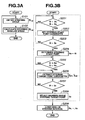
- FIGS. 3A and 3B are flowcharts showing a steering angular speed calculation process and a driving skill judgment process.
- FIGS. 4A ⁇ 4E are illustration views for illustrating an operation of a driving skill judgment calculation device.
- FIG. 5 is an illustrative view for illustrating a residual between a high order function and a record of a steering angle.
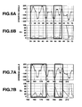
- FIG. 6A is a graph showing a record of the steering angle of an advanced driver.
- FIG. 6B is a graph showing a mean square of a residual between the record of the steering angle of the advanced driver and a cubic function.
- FIG. 7A is a graph showing a record of the steering angle of an intermediate driver.
- FIG. 7B is a graph showing a mean square of a residual between the record of the steering angle of the intermediate driver and a cubic function.
- FIG. 8A is a record of the steering angle of a beginning driver.
- FIG. 8B is a graph showing a mean square of a residual between the record of the steering angle of the beginning driver and a cubic function.
- FIG. 9A is a graph showing a record of the steering angle of an advanced driver.
- FIG. 9B is a graph showing a mean square of a residual between the record of the steering angle of the advanced driver and a quintic function.
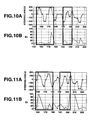
- FIG. 10A is a graph showing a record of the steering angle of an intermediate driver.
- FIG. 10B is a graph showing a mean square of a residual between the record of the steering angle of the intermediate driver and a quintic function.
- FIG. 11A is a record of the steering angle of a beginning driver.
- FIG. 11B is a graph showing a mean square of a residual between the record of the steering angle of the beginning driver and a quintic function.
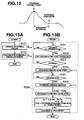
- FIG. 12 is an illustrative view for illustrating a variation of a driving skill judging process according to the embodiment.
- FIGS. 13A and 13B are flowcharts showing a variation of a steering angular speed calculation process and a driving skill judging process according to the embodiment.
- FIG. 14 is an illustrative view for illustrating a variation vehicle according to the embodiment.
- FIG. 1 is a schematic view showing a vehicle according to one embodiment.
- the vehicle includes a steering angle sensor 1, an output angle sensor 2, a vehicle speed sensor 3, a driving skill judgment calculation device 4, a variable steering angle calculation unit 5, and a variable steering angle mechanism 6.
- Steering angle sensor 1 is arranged to detect a steering angle of a steering wheel 7, and to output that detection result to variable steering angle calculation unit 5 and variable steering angle mechanism 6.
- Output angle sensor 2 is arranged to detect an output angle of a steering shaft 8, and to output that detection result to variable steering angle calculation unit 5 and variable steering angle mechanism 6.
- Vehicle sensor 3 is arranged to detect a running speed of the vehicle, and to output that detection result to variable steering angle calculation unit 5 and variable steering angle mechanism 6.
- Driving skill judgment calculation device 4 is arranged to perform a steering angular speed calculation process described later, to obtain the steering angle detected by steering angle sensor 1, and to calculate a steering angular speed. Moreover, driving skill judgment calculation device 4 is arranged to perform a driving skill judging process described later, and to detect a steering start point indicating that the steering is started, and a steering target point indicating that the steering is returned, based on the steering angle and the steering angular speed calculated by the steering angular speed calculating process. Moreover, driving skill judgment calculation device 4 is arranged to calculate a cubic function and a quintic function for approximating a transition state of the steering angle based on a record (historical data) of the steering angle from the steering start point to the steering target point.
- Driving skill judgment calculation device 4 is arranged to calculate a difference between the cubic function and the record of the steering angle, and a difference between the quintic function and the record of the steering angle, to judge the driving skill based on these differences, and to output the judgment result to variable steering angle mechanism 6.
- Variable steering angle mechanism 6 is configured to set a ratio of an output angle (actual steering angle) to an input angle of steering shaft 8 (the steering angle of steering wheel 7), in accordance with the detection results outputted from steering angle sensor 1, output angle sensor 2 and vehicle speed sensor 3. Moreover, variable steering angle mechanism 6 is configured to set a characteristic (steering angle variable algorism) of the ratio of the output angle to the input angle of steering shaft 8, to a value suitable for the driving skill.
- FIG. 3A is a flowchart showing a steering angular speed calculation process.
- driving skill judgment calculation device 4 obtains information of steering angle ⁇ i detected by steering angle sensor 1 at step S101, and the process proceeds to step S102
- driving skill judgment calculation device 4 calculates d ⁇ i/dt (steering angular speed) based on steering angle ⁇ i obtained at step S101, and then the process proceeds to step S101.
- FIG. 3B is a flowchart showing a driving skill judgment calculation process performed by driving skill judgment calculation device 4.
- driving skill judgment calculation device 4 judges whether or not the driver stops the steering at step S201, that is, judges whether or not steering angle ⁇ i is smaller than a first setting value ⁇ a and d ⁇ i/dt is smaller than a second setting value d ⁇ b/dt ( ⁇ i ⁇ a, d ⁇ i/dt ⁇ d ⁇ b/dt).
- step S201 YES ( ⁇ i ⁇ a and d ⁇ i/dt ⁇ d ⁇ b/dt)
- the process proceeds to step S202.
- step S201 is NO ( ⁇ i ⁇ a or d ⁇ i/dt ⁇ d ⁇ b/dt)
- the process repeats step S201.
- driving skill judgment calculation device 4 sets steering angles ⁇ i obtained by the steering angular speed calculation process, to steering start point candidates as shown in FIG. 4A .
- driving skill judgment calculation device 4 judges whether or not the driver is steering, that is, judges whether or not steering angular speed d ⁇ i/dt is greater than a third setting value d ⁇ c/dt.
- step S203 judges whether or not the driver is steering, that is, judges whether or not steering angular speed d ⁇ i/dt is greater than a third setting value d ⁇ c/dt.
- driving skill judgment calculation device 4 sets, to a steering start point ⁇ s, one steering angle ⁇ i set to the steering start point candidates at step S202, as shown in FIG. 4B .
- driving skill judgment calculation device 4 judges whether or not the steering angle reaches a maximum value, that is, judges whether or not the steering angle ⁇ i is equal to or greater than a fourth setting value ⁇ d and the steering angular speed d ⁇ i/dt is smaller than second setting value d ⁇ b/dt ( ⁇ i ⁇ d, d ⁇ i/dt ⁇ d ⁇ b/dt).
- step S205 When the answer of step S205 is YES ( ⁇ i ⁇ d and d ⁇ i/dt ⁇ d ⁇ b/dt), the process proceeds to step S206.
- step S205 When the answer of step S205 is NO ( ⁇ i ⁇ d or d ⁇ i/dt ⁇ d ⁇ b/dt), the process repeats step S205.
- step S206 driving skill judgment calculation device 4 sets (adds) steering angles ⁇ i obtained by the steering angular speed calculating process, to steering target point candidates as shown in FIG. 4C .
- step S207 driving skill judgment calculation device 4 judges whether or not the steering angle ⁇ i is smaller than third setting value ⁇ c ( ⁇ i ⁇ c).
- step S208 When the answer of step S207 is YES ( ⁇ i ⁇ c), the process proceeds to step S208.
- step S207 is NO ( ⁇ i ⁇ c)
- the process proceeds to step S206.
- driving skill judgment calculation device 4 sets, to steering target point ⁇ e, maximum one of the steering target point candidates set at step S206, as shown in FIG. 4D .
- driving skill judgment calculation device 4 calculates (determines) the cubic function and the quintic function for approximating the transition state of the steering angle based on the record ⁇ s ⁇ e of the steering angles in the steering interval from steering start point ⁇ s set at step S204 to steering target point ⁇ e set at step S208.
- square of the residual between cubic function f 3 with unknown coefficients and the record ⁇ s ⁇ e of the steering angles is represented as follows.
- ⁇ j s e ⁇ f 3 t j - ⁇ j ⁇ ⁇ 2
- equations (3) are represented in matrix representation as follows.
- driving skill judgment calculation device 4 judges the driving skill based on the calculated mean square En of the residual, and the judgment result is outputted to variable steering angle mechanism 6. For example, driving skill judgment calculation device 4 determines the advanced driver (experienced driver) when mean square En of the residual between the cubic function f 3 and the record ⁇ s ⁇ e of the steering angles is equal to or smaller than a fifth setting value, that is a setting value which is determined in advance by an experiment, a simulation and so on, and which is for judging whether the driver is the advanced driver or the intermediate driver and the beginning driver. Driving skill judgment calculation device 4 determines the intermediate driver or the beginning driver when the mean square En is greater than the fifth setting value.
- a fifth setting value that is a setting value which is determined in advance by an experiment, a simulation and so on
- driving skill judgment calculation device 4 determines the advanced driver or the intermediate driver when mean square En of the residual between the quintic function f 5 and the record ⁇ s ⁇ e of the steering angles is equal to or smaller than a sixth setting value, that is a setting value which is determined in advance by an experiment, a simulation and so on, and which is for judging the advanced driver and the intermediate driver or the beginning driver.
- Driving skill judgment calculation device 4 determines the beginning driver when the mean square En is greater than the sixth setting value.
- driving skill judgment calculation device 4 judges whether or not mean square En of the residual between cubic function f 3 and the record ⁇ s ⁇ e of the steering angles is equal to or lower than the fifth setting value. Driving skill judgment calculation device 4 determines the advanced driver when the mean square En is equal to or smaller than the fifth setting value. Moreover, in the case in which the mean square En is greater than the fifth setting value, driving skill judgment calculation device 4 judges whether or not mean square En of the residual between quintic function f 5 and the record ⁇ s ⁇ e of the steering angles is equal to or smaller than the sixth setting value. Driving skill judgment calculation device 4 determines the intermediate driver when the mean square En is equal to or smaller than the sixth setting value. Driving skill judgment calculation device 4 determines the begging driver when the mean square En is greater than the sixth setting value.
- the driver determines the steering angle from various information such as ambient environment when the driver steers.
- the advanced driver can predict the movement of the vehicle by the steering, changes of the surrounding circumstance.
- the advanced driver determines the target angle in advance, and steers from the steering start to the steering stop without adjustment of the target. Accordingly, the record of the steering angles of the advanced driver are approximated by the lower order function.
- the beginning driver can not predict the vehicle movement and the changes of the surrounding circumstance, and adjusts the steering movement depending on the states of the time.
- the beginning driver adjusts the target steering angle by the information of the surrounding circumstance and the vehicle movement from the steering start to the steering stop. Therefore, it is not possible to appropriately approximate the record of the steering angles by the low order function, and the record of the steering angles of the beginning driver are approximated by the higher order function relative to the advanced driver.
- FIG. 6A is a graph showing a record of steering angles of an advanced driver having a driving experience of 30 years when the driver drives on gradual continuous curves.
- FIG. 6B is a graph showing a mean square E 3 of a residual between the record of the steering angle of the advanced driver and a cubic function.
- FIG. 7A is a graph showing a record of steering angles of an intermediate driver having a driving experience of 10 years when the driver drives on the gradual continuous curves.
- FIG. 7B is a graph showing a mean square E 3 of a residual between the record of the steering angles of the intermediate driver and a cubic function.
- FIG. 8A is a record of steering angles of a beginning driver who is a Sunday driver when the driver drives on the gradual continuous curves.
- FIG. 8A is a record of steering angles of a beginning driver who is a Sunday driver when the driver drives on the gradual continuous curves.
- FIG. 8B is a graph showing a mean square E 3 of a residual between the record of the steering angles of the beginning driver and a cubic function. From these graphs, the residual of the advanced driver is small in whole (20° or below, FIG. 6B ). The residual of the intermediate driver is large from the steering start point to the steering target point ( FIG. 7B ). The residual of the beginning driver is large in whole ( FIG. 8B ).
- FIG. 9A is a graph showing a record of steering angles of an advanced driver having the driving experience of 30 years when the driver drives on gradual continuous curves.
- FIG. 9B is a graph showing a mean square E 5 of a residual between the record of the steering angles of the advanced driver and a quintic function.
- FIG. 10A is a graph showing a record of steering angles of an intermediate driver having the driving experience of 10 years when the driver drives on the gradual continuous curves.
- FIG. 10B is a graph showing a mean square E 5 of a residual between the record of the steering angles of the intermediate driver and a quintic function.
- FIG. 11A is a record of steering angles of a beginning driver who is a Sunday driver when the driver drives on the gradual continuous curves.
- 11B is a graph showing a mean square E 5 of a residual between the record of the steering angles of the beginning driver and a quintic function. From these graphs, the residual of the advanced driver is small in whole (substantially zero, FIG. 9 ). The residual of the intermediate driver is small ( FIG. 10 ). The residual of the beginning driver is large in whole ( FIG. 11 ).
- steering angle sensor 1 of FIG. 1 corresponds to a steering angle detecting section.
- Driving skill judgment calculation device 4 and step S209 of FIG. 3B corresponds to a high order function calculating section and a skill judging section.
- Step S209 of FIG. 3B corresponds to an approximation function calculating section and a steering end point detecting section.
- Steps S201 ⁇ S204 of FIG. 3B correspond to a steering start point sensing section.
- Step S208 of FIG. 3B corresponds to a steering target point detecting section.
- Variable steering angle mechanism 6 of FIG. 1 corresponds to a variable gear ratio steering device.
- the driving skill judging apparatus includes a steering angle detecting section configured to detect a steering angle of the vehicle; a high order function calculating section configured to calculate a high order function of a third order or more, and which is for approximating a transition state of the steering angle based on the steering angle detected by the steering angle detecting section; and a skill judging section configured to judge a driving skill based on a comparative result between a transition state of the steering angle detected by the steering angle detecting section and the high order function calculated by the high order function calculating section. Therefore, it is possible to achieve the judgment of the driving skill by the simple structure, relative to the method of judging the driving skill by using the road alignments and so on.
- the jerk of the steering angle is obtained by performing the third order derivative of the steering angle detected by steering angle sensor 1, by performing the second order derivative of the steering angular speed detected by the steering angular speed sensor, or by performing the first order derivative of the steering angular acceleration sensed by the steering angular acceleration sensor.
- the sensor outputs are a discrete-time system, and it is not possible to differentiate directly by the sensor outputs.
- the pseudo-differential value is obtained by the differences between the plurality of the samples, instead of the differential.
- the accuracy is enormously deteriorated. Therefore, it is not possible to obtain the jerk by the difference.
- the high order function to approximate the transition state of the steering angle is calculated without directly calculating the jerk. The driving skill is judged based on the difference between the high order function and the steering angle, that is, based on the value indirectly indicating the magnitude of the jerk.
- the high order function calculating section calculates a first high order function (cubic function) of a third order or more, and a second high order function (quintic function) of an order larger than the order of the first high order function; and the skill judging section is configured to judge the driving skill based on a difference between the transition state of the steering angle and the first high order function, and a difference between the transition state of the steering angle and the second high order function. Accordingly, it is possible to achieve the judgment of the driving skill by the simple construction, relative to the method of judging the driving skill by using the road alignments.
- the high order function calculating section includes a steering start point detecting section configured to detect a steering start point indicating a point at which the steering is started, based on the record of the steering angle; a steering target point detecting section configured to detect a steering target point indicating a point at which the steering is returned, based on the record of the steering angle; and an approximation function calculating section configured to calculate the first high order function and the second high order function for approximating the transition state of the steering angle from the steering start point to the steering target point, based on the record of the steering angle. Accordingly, it is possible to achieve the judgment of the driving skill by the simple construction, relative to the method of judging the driving skill by using the road alignments.
- the high order function calculating section includes a steering target point detecting section configured to detect a steering target point indicating a point at which the steering is returned, based on the record of the steering angle; a steering end point detecting section configured to detect a steering end point indicating a point at which the steering is finished, based on the record of the steering angle; an approximation function calculating section configured to calculate the first high order function and the second high order function for approximating the transition state of the steering angle from the steering target point to the steering end point, based on the record of the steering angle, as shown in FIG. 12 . Accordingly, it is possible to achieve the judgment of the driving skill by the simple construction, relative to the method of judging the driving skill by using the road alignments.
- FIG. 13 is a flowchart showing a variation of a steering angular speed calculation process and a driving skill judging process according to the embodiment.
- driving skill judgment calculation device detects the steering start point from the record of the steering angles (step S201 ⁇ S204), detects the steering end point from the record of the steering angles (step S301), and calculates the first high order function and the second high order function for approximating the transition state of the steering angle from the steering start point to the steering end point (step S209). Accordingly, it is possible to achieve the judgment of the driving skill by the simple construction, relative to the method of judging the driving skill by using the road alignments.
- the first high order function is a cubic function
- the second high order function is a quintic function. Accordingly, it is possible to estimate the variation of the jerk by the cubic function, and to estimate the degree of the suppression of the variation of the jerk. Therefore, it is possible to simplify the judgment algorism.
- the steering start point detecting section determines the steering start point when an absolute value of variation speed of the steering angle becomes greater than a third threshold value (third setting value) from a state in which the absolute value of the steering angle is smaller than a first threshold value (first setting value) and the absolute value of the variation speed of the steering angle is smaller than a second threshold value (second setting value). Accordingly, it is possible to detect that the vehicle running the straight road turns right or left on the intersections, and approaches the curve road. Therefore, it is possible to appropriately obtain only the data of the steering angle at the steering.
- the steering end point detecting section determines the steering end point when an absolute value of a variation quantity of the steering angle becomes smaller than a sixth threshold value from a state in which the absolute value of the steering angle is smaller than a fourth threshold value and the absolute value of the variation speed of the steering angle is greater than a fifth threshold value. Accordingly, it is possible to appropriately detect that the vehicle turns right or left on the intersections, and returns from the curve road to the straight road.
- the steering target point sensing section determines the steering target point when the steering angle is maximized. Accordingly, it is possible to prevent the deterioration of the judgment accuracy of the driving skill by change of steering strategies when the steering wheel is steered to the target point, and when the steering wheel is returned. Therefore, it is possible to improve the judgment accuracy of the driving skill.
- the high order function calculating section is configured to calculate the high order function by least square method, based on the steering angle. Accordingly, it is possible to decrease the calculation for determining the high order function, and to improve the judgment speed of the driving skill.
- the skill judging section is configured to judge the driving skill based on mean square of difference between the transition state of the steering angle and the high order function. Accordingly, it is possible to judge the driving skill concurrently with the determination (calculation) of the high order function. Moreover, it is possible to eliminate the influence of the time period of the steering, and to prevent the deterioration of the judgment accuracy which is caused by the difference of the road alignments. Therefore, it is possible to improve the judgment speed and the judgment accuracy of the driving skill.
- variable steering apparatus is arranged to control a ratio between the steering angle and an actual steering angle based on the judgment result of the driving skill. Accordingly, it is possible to judge the driving skill by using the steering angle sensor which is originally provided to the variable gear ratio steering device, and to change the steering angle variable algorism in accordance with the judgment result of the driving skill. Therefore, it is possible to attain the steering apparatus to perform the steering near the feeling of the driver.
- FIG. 14 is an illustrative view for illustrating a variation vehicle according to the embodiment.
- the variable steering apparatus of FIG. 14 includes an electromotive power steering device arranged to assist a steering force, and to set a characteristic of the assist of the steering force based on the judgment result of the driving skill. Accordingly, it is possible to attain the steering apparatus to stabilize the movement of the vehicle at the steering.
- the vehicle according to the embodiment includes a steering wheel; a steering angle detecting section configured to detect a steering angle of the steering wheel; a high order function calculating section configured to calculate a high order function of a third order or more, and which is for approximating a transition state of the steering angle based on the steering angle detected by the steering angle detecting section; and a skill judging section configured to judge a driving skill based on a comparative result between a transition state of the steering angle detected by the steering angle detecting section and the high order function calculated by the high order function calculating section. Accordingly, it is possible to achieve the judgment of the driving skill by the simple construction, relative to the method of judging the driving skill by using the road alignments.
- a driving skill judging method includes: detecting a steering angle of the vehicle; calculating a high order function of a third order or more, and which is for approximating a transition state of the steering angle based on the steering angle; and judging a driving skill based on a comparative result between a transition state of the steering angle detected by the steering angle detecting section and the high order function. Accordingly, it is possible to achieve the judgment of the driving skill by the relatively simple construction, relative to the method of judging the driving skill by using the road alignments.
Landscapes
- Engineering & Computer Science (AREA)
- Transportation (AREA)
- Mechanical Engineering (AREA)
- Chemical & Material Sciences (AREA)
- Combustion & Propulsion (AREA)
- Physics & Mathematics (AREA)
- Mathematical Physics (AREA)
- Automation & Control Theory (AREA)
- Steering Control In Accordance With Driving Conditions (AREA)
- Power Steering Mechanism (AREA)
Claims (14)
- Vorrichtung zur Bewertung von Fahrfähigkeiten für ein Fahrzeug, umfassend:einen Lenkwinkel-Erfassungsabschnitt (1) zum Erfassen eines Lenkwinkels des Fahrzeugs;einen Berechnungsabschnitt (4, S209) für eine Funktion höherer Ordnung zum Berechnen einer Funktion höherer Ordnung einer dritten Ordnung oder höher,und zum Annähern eines Übergangszustandes des Lenkwinkels auf der Grundlage des von dem Lenkwinkel-Erfassungsabschnitt erfassten Lenkwinkels; undeinen Fähigkeitsbewertungsabschnitt (4, S209) zum Bewerten einer Fahrfähigkeit auf der Grundlage eines Vergleichsergebnisses zwischen einem Übergangszustand des von dem Lenkwinkel-Erfassungsabschnitt erfassten Lenkwinkels und der Funktion höherer Ordnung, die von dem Berechnungsabschnitt (4, S209) für eine Funktion höherer Ordnung berechnet wurde.
- Vorrichtung zur Bewertung von Fahrfähigkeiten nach Anspruch 1, wobei der Berechnungsabschnitt (4, S209) für eine Funktion höherer Ordnung eine erste Funktion höherer Ordnung einer dritten Ordnung oder höher und eine zweite Funktion höherer Ordnung einer Ordnung, die größer als die Ordnung der ersten Funktion höherer Ordnung ist, berechnet; und der Fähigkeitsbewertungsabschnitt (4, S209) ausgelegt ist, die Fahrfähigkeit auf der Grundlage eines Unterschieds zwischen dem Übergangszustand des Lenkwinkels und der ersten Funktion höherer Ordnung und eines Unterschieds zwischen dem Übergangszustand des Lenkwinkels und der zweiten Funktion höherer Ordnung zu bewerten.
- Vorrichtung zur Bewertung von Fahrfähigkeiten nach Anspruch 2, wobei der Berechnungsabschnitt (4, S209) für eine Funktion höherer Ordnung umfasst:einen Lenkstartpunkt-Erfassungsabschnitt (S201-S204), der ausgelegt ist,einen Lenkstartpunkt, der einen Punkt angibt, an dem die Lenkung gestartet wird, auf der Grundlage der Aufzeichnung des Lenkwinkels zu erfassen; einen Lenkzielpunkt-Erfassungsabschnitt (S208), der ausgelegt ist, einen Lenkzielpunkt, der einen Punkt angibt, an dem die Lenkung umkehrt, auf der Grundlage der Aufzeichnung des Lenkwinkels zu erfassen; und einen Annäherungsfunktion-Berechnungsabschnitt (S209), der ausgelegt ist, auf der Grundlage der Aufzeichnung des Lenkwinkels die erste Funktion höherer Ordnung und die zweite Funktion höherer Ordnung zu berechnen, um den Übergangszustand des Lenkwinkels vom Lenkstartpunkt zum Lenkzielpunkt anzunähern.
- Vorrichtung zur Bewertung von Fahrfähigkeiten nach Anspruch 2, wobei der Berechnungsabschnitt (4, S209) für eine Funktion höherer Ordnung umfasst:einen Lenkzielpunkt-Erfassungsabschnitt (S208), der ausgelegt ist, einen Lenkzielpunkt, der einen Punkt angibt, an dem die Lenkung umkehrt, auf der Grundlage der Aufzeichnung des Lenkwinkels zu erfassen; einen Lenkendpunkt-Erfassungsabschnitt (S209), der ausgelegt ist, einen Lenkendpunkt, der einen Punkt angibt, an dem die Lenkung beendet ist, auf der Grundlage der Aufzeichnung des Lenkwinkels zu erfassen; einen Annäherungsfunktion-Berechnungsabschnitt (S209), der ausgelegt ist, auf der Grundlage der Aufzeichnung des Lenkwinkels die erste Funktion höherer Ordnung und die zweite Funktion höherer Ordnung zu berechnen, um den Übergangszustand des Lenkwinkels vom Lenkzielpunkt zum Lenkendpunkt anzunähern.
- Vorrichtung zur Bewertung von Fahrfähigkeiten nach Anspruch 3 oder 4, wobei die erste Funktion höherer Ordnung eine Funktion dritter Ordnung ist; und die zweite Funktion höherer Ordnung eine Funktion fünfter Ordnung ist.
- Vorrichtung zur Bewertung von Fahrfähigkeiten nach Anspruch 3, wobei der Lenkstartpunkt-Erfassungsabschnitt (S201-S204) den Lenkstartpunkt bestimmt, wenn ein absoluter Wert der Veränderungsgeschwindigkeit des Lenkwinkels größer wird als ein dritten Schwellenwert, ab einem Zustand, in dem der absolute Wert des Lenkwinkels kleiner als ein erster Schwellenwert ist und der absolute Wert der Veränderungsgeschwindigkeit des Lenkwinkels kleiner als ein zweite Schwellenwert ist.
- Vorrichtung zur Bewertung von Fahrfähigkeiten nach Anspruch 4, wobei der Lenkendpunkt-Erfassungsabschnitt (S209) den Lenkendpunkt bestimmt, wenn ein absoluter Wert der Veränderungsmenge des Lenkwinkels größer wird als ein sechster Schwellenwert, ab einem Zustand, in dem der absolute Wert des Lenkwinkels kleiner als ein vierter Schwellenwert ist und der absolute Wert der Veränderungsgeschwindigkeit des Lenkwinkels größer als ein fünfter Schwellenwert ist.
- Vorrichtung zur Bewertung von Fahrfähigkeiten nach einem der Ansprüche 3 bis 6, wobei der Lenkzielpunkt-Erfassungsabschnitt (S209) den Lenkzielpunkt bestimmt, wenn der Lenkwinkel maximiert ist.
- Vorrichtung zur Bewertung von Fahrfähigkeiten nach Anspruch 1 oder 2, wobei der Berechnungsabschnitt (4, S209) für eine Funktion höherer Ordnung ausgelegt ist, die Funktion höherer Ordnung durch die Kleinstquadratmethode auf der Grundlage des Lenkwinkels zu berechnen.
- Vorrichtung zur Bewertung von Fahrfähigkeiten nach einem der Ansprüche 1 bis 9, wobei der Fähigkeitsbewertungsabschnitt (4, S209) ausgelegt ist, die Fahrfähigkeit auf der Grundlage eines mittleren Quadrats der Differenz zwischen dem Übergangszustand des Lenkwinkels und der Funktion höherer Ordnung zu bewerten.
- Variable Lenkvorrichtung für ein Fahrzeug, umfassend:einen Lenkwinkel-Erfassungsabschnitt (1) zum Erfassen eines Lenkwinkels des Fahrzeugs;einen Berechnungsabschnitt (4, S209) für eine Funktion höherer Ordnung zum Berechnen einer Funktion höherer Ordnung einer dritten Ordnung oder höher,und zum Annähern eines Übergangszustandes des Lenkwinkels auf der Grundlage des von dem Lenkwinkel-Erfassungsabschnitt erfassten Lenkwinkels;einen Fähigkeitsbewertungsabschnitt (4, S209) zum Bewerten einer Fahrfähigkeit auf der Grundlage eines Vergleichsergebnisses zwischen einem Übergangszustand des von dem Lenkwinkel-Erfassungsabschnitt erfassten Lenkwinkels und der Funktion höherer Ordnung, die von dem Berechnungsabschnitt (4, S209) für eine Funktion höherer Ordnung berechnet wurde; undeine Lenkvorrichtung (6) mit variablem Übersetzungsverhältnis, um ein Verhältnis zwischen einem Lenkwinkel und einem Ist-Lenkwinkel auf der Grundlage des Bewertungsergebnisses der Fahrfähigkeit durch den Fähigkeitsbewertungsabschnitt zu steuern.
- Variable Lenkvorrichtung für ein Fahrzeug, umfassend:einen Lenkwinkel-Erfassungsabschnitt (1) zum Erfassen eines Lenkwinkels des Fahrzeugs;einen Berechnungsabschnitt (4, S209) für eine Funktion höherer Ordnung zum Berechnen einer Funktion höherer Ordnung einer dritten Ordnung oder höher,und zum Annähern eines Übergangszustandes des Lenkwinkels auf der Grundlage des von dem Lenkwinkel-Erfassungsabschnitt erfassten Lenkwinkels;einen Fähigkeitsbewertungsabschnitt (4, S209) zum Bewerten einer Fahrfähigkeit auf der Grundlage eines Vergleichsergebnisses zwischen einem Übergangszustand des von dem Lenkwinkel-Erfassungsabschnitt erfassten Lenkwinkels und der Funktion höherer Ordnung, die von dem Berechnungsabschnitt (4, S209) für eine Funktion höherer Ordnung berechnet wurde; undeine elektromotorische Servolenkvorrichtung, um eine Lenkkraft zu unterstützen und eine Kennlinie der Unterstützung der Lenkkraft auf der Grundlage des Bewertungsergebnisses der Fahrfähigkeit durch den Fähigkeitsbewertungsabschnitt festzulegen.
- Fahrzeug, umfassend:ein Lenkrad (7);einen Lenkwinkel-Erfassungsabschnitt (1) zum Erfassen eines Lenkwinkels des Fahrzeugs;einen Berechnungsabschnitt (4, S209) für eine Funktion höherer Ordnung zum Berechnen einer Funktion höherer Ordnung einer dritten Ordnung oder höher,und zum Annähern eines Übergangszustandes des Lenkwinkels auf der Grundlage des von dem Lenkwinkel-Erfassungsabschnitt erfassten Lenkwinkels; undeinen Fähigkeitsbewertungsabschnitt (4, S209) zum Bewerten einer Fahrfähigkeit auf der Grundlage eines Vergleichsergebnisses zwischen einem Übergangszustand des von dem Lenkwinkel-Erfassungsabschnitt erfassten Lenkwinkels und der Funktion höherer Ordnung, die von dem Berechnungsabschnitt (4, S209) für eine Funktion höherer Ordnung berechnet wurde.
- Verfahren zur Bewertung von Fahrfähigkeiten für ein Fahrzeug, umfassend:Erfassen eines Lenkwinkels des Fahrzeugs;Berechnen einer Funktion höherer Ordnung einer dritten Ordnung oder höher,und die zum Annähern eines Übergangszustandes des Lenkwinkels auf der Grundlage des Lenkwinkels dient; undBewerten einer Fahrfähigkeit auf der Grundlage eines Vergleichsverhältnisses zwischen einem Übergangszustand des vom Lenkwinkel-Erfassungsabschnitt erfassten Lenkwinkels und der Funktion höherer Ordnung.
Applications Claiming Priority (1)
| Application Number | Priority Date | Filing Date | Title |
|---|---|---|---|
| JP2007122135A JP5169011B2 (ja) | 2007-05-07 | 2007-05-07 | 運転技量判定装置、可変操舵装置、自動車及び運転技量判定方法 |
Publications (2)
| Publication Number | Publication Date |
|---|---|
| EP1990259A1 EP1990259A1 (de) | 2008-11-12 |
| EP1990259B1 true EP1990259B1 (de) | 2011-01-26 |
Family
ID=39689046
Family Applications (1)
| Application Number | Title | Priority Date | Filing Date |
|---|---|---|---|
| EP08008133A Not-in-force EP1990259B1 (de) | 2007-05-07 | 2008-04-28 | Vorrichtung zur Bewertung der Fahrerfahung sowie variable Lenkvorrichtung, Fahrzeug und Verfahren zur Bewertung der Fahrerfahrung |
Country Status (4)
| Country | Link |
|---|---|
| US (1) | US8068953B2 (de) |
| EP (1) | EP1990259B1 (de) |
| JP (1) | JP5169011B2 (de) |
| DE (1) | DE602008004688D1 (de) |
Families Citing this family (10)
| Publication number | Priority date | Publication date | Assignee | Title |
|---|---|---|---|---|
| JP4602444B2 (ja) * | 2008-09-03 | 2010-12-22 | 株式会社日立製作所 | ドライバ運転技能支援装置及びドライバ運転技能支援方法 |
| IT1398073B1 (it) * | 2010-02-19 | 2013-02-07 | Teleparking S R L | Sistema e metodo di stima dello stile di guida di un autoveicolo |
| SG190334A1 (en) | 2010-12-10 | 2013-06-28 | Basf Se | Aqueous polishing composition and process for chemically mechanically polishing substrates containing silicon oxide dielectric and polysilicon films |
| US8731736B2 (en) | 2011-02-22 | 2014-05-20 | Honda Motor Co., Ltd. | System and method for reducing driving skill atrophy |
| JP5578331B2 (ja) | 2011-12-26 | 2014-08-27 | トヨタ自動車株式会社 | 車両の走行軌跡制御装置 |
| JP5510471B2 (ja) * | 2012-01-20 | 2014-06-04 | トヨタ自動車株式会社 | 運転モデルの作成装置及び運転モデルの作成方法、並びに運転評価装置及び運転評価方法、並びに運転支援システム |
| US9511778B1 (en) * | 2014-02-12 | 2016-12-06 | XL Hybrids | Controlling transmissions of vehicle operation information |
| US9573600B2 (en) * | 2014-12-19 | 2017-02-21 | Toyota Motor Engineering & Manufacturing North America, Inc. | Method and apparatus for generating and using driver specific vehicle controls |
| JP6372431B2 (ja) * | 2015-06-29 | 2018-08-15 | トヨタ自動車株式会社 | 衝突予測装置 |
| JP7303153B2 (ja) * | 2020-05-18 | 2023-07-04 | トヨタ自動車株式会社 | 車両用運転支援装置 |
Family Cites Families (19)
| Publication number | Priority date | Publication date | Assignee | Title |
|---|---|---|---|---|
| JPH045077A (ja) * | 1990-04-23 | 1992-01-09 | Oji Paper Co Ltd | 感熱記録材料 |
| JP2639179B2 (ja) * | 1990-06-19 | 1997-08-06 | 日産自動車株式会社 | 車両の運転操作補償装置 |
| JPH06191315A (ja) * | 1992-12-22 | 1994-07-12 | Toyota Motor Corp | 車両制御装置 |
| US5991675A (en) * | 1993-06-02 | 1999-11-23 | Honda Giken Kogyo Kabushiki Kaisha | Vehicle control system based on estimation of the driving skill of a vehicle operator |
| JP3516986B2 (ja) * | 1993-06-02 | 2004-04-05 | 本田技研工業株式会社 | 運転技量推定装置 |
| JP3269296B2 (ja) * | 1994-11-29 | 2002-03-25 | 日産自動車株式会社 | 運転技量検出装置及び車両運動制御装置 |
| JP3411460B2 (ja) * | 1997-01-09 | 2003-06-03 | 本田技研工業株式会社 | 車両用運転状況監視装置 |
| JP3393322B2 (ja) * | 1997-01-09 | 2003-04-07 | 本田技研工業株式会社 | 車両用運転状況監視装置 |
| JP2002154346A (ja) * | 2000-11-22 | 2002-05-28 | Nissan Motor Co Ltd | 運転者操作特性評価方法及び装置 |
| JP2003083108A (ja) * | 2001-09-14 | 2003-03-19 | Nissan Motor Co Ltd | 運転者能力判定装置 |
| JP4135598B2 (ja) * | 2003-09-01 | 2008-08-20 | 日産自動車株式会社 | 運転者操舵技量判定装置 |
| JP2006111098A (ja) * | 2004-10-13 | 2006-04-27 | Nissan Motor Co Ltd | 車両用運転支援装置 |
| JP2006111226A (ja) * | 2004-10-18 | 2006-04-27 | Nissan Motor Co Ltd | 車両用操舵制御装置 |
| JP2006232172A (ja) * | 2005-02-25 | 2006-09-07 | Nissan Motor Co Ltd | 車両用運転支援装置 |
| JP2006232174A (ja) * | 2005-02-25 | 2006-09-07 | Nissan Motor Co Ltd | 車両用運転支援装置 |
| JP2006232173A (ja) * | 2005-02-25 | 2006-09-07 | Nissan Motor Co Ltd | 運転者操舵技量判定装置 |
| JP2007122135A (ja) | 2005-10-25 | 2007-05-17 | Hitachi Ltd | 開発支援装置、開発支援方法、および、開発支援プログラム |
| US20070213886A1 (en) * | 2006-03-10 | 2007-09-13 | Yilu Zhang | Method and system for driver handling skill recognition through driver's steering behavior |
| US7649445B2 (en) * | 2006-06-15 | 2010-01-19 | The Yokohama Rubber Co., Ltd. | Apparatus and method for evaluating driving skill and apparatus and method for informing efficiency of driver's physical load to driving operation |
-
2007
- 2007-05-07 JP JP2007122135A patent/JP5169011B2/ja not_active Expired - Fee Related
-
2008
- 2008-04-28 EP EP08008133A patent/EP1990259B1/de not_active Not-in-force
- 2008-04-28 DE DE602008004688T patent/DE602008004688D1/de active Active
- 2008-04-30 US US12/149,356 patent/US8068953B2/en not_active Expired - Fee Related
Also Published As
| Publication number | Publication date |
|---|---|
| US20080281486A1 (en) | 2008-11-13 |
| US8068953B2 (en) | 2011-11-29 |
| JP5169011B2 (ja) | 2013-03-27 |
| JP2008273465A (ja) | 2008-11-13 |
| DE602008004688D1 (de) | 2011-03-10 |
| EP1990259A1 (de) | 2008-11-12 |
Similar Documents
| Publication | Publication Date | Title |
|---|---|---|
| EP1990259B1 (de) | Vorrichtung zur Bewertung der Fahrerfahung sowie variable Lenkvorrichtung, Fahrzeug und Verfahren zur Bewertung der Fahrerfahrung | |
| CN102975716B (zh) | 用于在自动化车道对中过程中的速度自适应转向超驰检测的系统和方法 | |
| CN103442970B (zh) | 车辆用信息处理装置 | |
| CN101346247B (zh) | 用于在停车或调车时辅助驾驶员的方法及系统 | |
| JP4062310B2 (ja) | 運転意図推定装置、車両用運転操作補助装置および車両用運転操作補助装置を備えた車両 | |
| CN104487307B (zh) | 用于检测机动车辆行驶方向的方法 | |
| EP2319741B1 (de) | Steuervorrichtung zur Fahrspurhaltung für ein Fahrzeug | |
| US10875575B2 (en) | Steering assistance device | |
| CN101472782A (zh) | 车辆状态量预测装置和使用该装置的车辆转向控制器以及预测车辆状态量的方法和使用该方法的车辆转向控制方法 | |
| US11465679B2 (en) | Method for detecting the presence of hands on the steering wheel | |
| CN110573406B (zh) | 用于探测位于方向盘上的手的方法 | |
| US20190176885A1 (en) | Method for Estimating Steering Wheel Torque of Vehicle | |
| WO2010084994A1 (en) | Driver operation prediction device, method, and driver operation prediction program | |
| CN109552402A (zh) | 用于在电动助力转向中检测路面状态的设备及其控制方法 | |
| KR101360440B1 (ko) | 차량용 차선 유지 제어방법 및 장치 | |
| JP5239947B2 (ja) | 運転操作支援装置及び運転操作支援方法 | |
| EP2873590B1 (de) | Handradwinkel aus dynamischen Sensoren oder Raddrehzahlen eines Fahrzeugs | |
| US20130304317A1 (en) | Reaction force control device | |
| US11235802B2 (en) | Enhanced vehicle operation | |
| KR20160066297A (ko) | 차선 유지 보조 시스템의 동작 개시 제어 장치 및 이의 제어 방법 | |
| KR101601330B1 (ko) | 차량의 곡선로 이탈 방지 장치 및 그 방법 | |
| JP4797891B2 (ja) | スロットル開度制御装置 | |
| JP2008225215A (ja) | ドライビングシミュレータ用操舵装置 | |
| JP5056192B2 (ja) | 車両用制御装置 | |
| JP4605200B2 (ja) | 運転意図推定装置、車両用運転操作補助装置および車両用運転操作補助装置を備えた車両 |
Legal Events
| Date | Code | Title | Description |
|---|---|---|---|
| PUAI | Public reference made under article 153(3) epc to a published international application that has entered the european phase |
Free format text: ORIGINAL CODE: 0009012 |
|
| 17P | Request for examination filed |
Effective date: 20080428 |
|
| AK | Designated contracting states |
Kind code of ref document: A1 Designated state(s): AT BE BG CH CY CZ DE DK EE ES FI FR GB GR HR HU IE IS IT LI LT LU LV MC MT NL NO PL PT RO SE SI SK TR |
|
| AX | Request for extension of the european patent |
Extension state: AL BA MK RS |
|
| AKX | Designation fees paid |
Designated state(s): DE FR GB |
|
| 17Q | First examination report despatched |
Effective date: 20100617 |
|
| GRAP | Despatch of communication of intention to grant a patent |
Free format text: ORIGINAL CODE: EPIDOSNIGR1 |
|
| GRAS | Grant fee paid |
Free format text: ORIGINAL CODE: EPIDOSNIGR3 |
|
| GRAA | (expected) grant |
Free format text: ORIGINAL CODE: 0009210 |
|
| AK | Designated contracting states |
Kind code of ref document: B1 Designated state(s): DE FR GB |
|
| REG | Reference to a national code |
Ref country code: GB Ref legal event code: FG4D |
|
| REF | Corresponds to: |
Ref document number: 602008004688 Country of ref document: DE Date of ref document: 20110310 Kind code of ref document: P |
|
| REG | Reference to a national code |
Ref country code: DE Ref legal event code: R096 Ref document number: 602008004688 Country of ref document: DE Effective date: 20110310 |
|
| PLBE | No opposition filed within time limit |
Free format text: ORIGINAL CODE: 0009261 |
|
| STAA | Information on the status of an ep patent application or granted ep patent |
Free format text: STATUS: NO OPPOSITION FILED WITHIN TIME LIMIT |
|
| 26N | No opposition filed |
Effective date: 20111027 |
|
| REG | Reference to a national code |
Ref country code: DE Ref legal event code: R097 Ref document number: 602008004688 Country of ref document: DE Effective date: 20111027 |
|
| REG | Reference to a national code |
Ref country code: FR Ref legal event code: PLFP Year of fee payment: 8 |
|
| PGFP | Annual fee paid to national office [announced via postgrant information from national office to epo] |
Ref country code: DE Payment date: 20150422 Year of fee payment: 8 Ref country code: GB Payment date: 20150422 Year of fee payment: 8 |
|
| PGFP | Annual fee paid to national office [announced via postgrant information from national office to epo] |
Ref country code: FR Payment date: 20150408 Year of fee payment: 8 |
|
| REG | Reference to a national code |
Ref country code: DE Ref legal event code: R119 Ref document number: 602008004688 Country of ref document: DE |
|
| GBPC | Gb: european patent ceased through non-payment of renewal fee |
Effective date: 20160428 |
|
| REG | Reference to a national code |
Ref country code: FR Ref legal event code: ST Effective date: 20161230 |
|
| PG25 | Lapsed in a contracting state [announced via postgrant information from national office to epo] |
Ref country code: GB Free format text: LAPSE BECAUSE OF NON-PAYMENT OF DUE FEES Effective date: 20160428 Ref country code: DE Free format text: LAPSE BECAUSE OF NON-PAYMENT OF DUE FEES Effective date: 20161101 Ref country code: FR Free format text: LAPSE BECAUSE OF NON-PAYMENT OF DUE FEES Effective date: 20160502 |