EP1990231A1 - Fahrzeugantriebsvorrichtung und verfahren zur steuerung einer fahrzeugantriebsvorrichtung - Google Patents
Fahrzeugantriebsvorrichtung und verfahren zur steuerung einer fahrzeugantriebsvorrichtung Download PDFInfo
- Publication number
- EP1990231A1 EP1990231A1 EP07707571A EP07707571A EP1990231A1 EP 1990231 A1 EP1990231 A1 EP 1990231A1 EP 07707571 A EP07707571 A EP 07707571A EP 07707571 A EP07707571 A EP 07707571A EP 1990231 A1 EP1990231 A1 EP 1990231A1
- Authority
- EP
- European Patent Office
- Prior art keywords
- rotating electric
- electric machine
- vehicle
- drive device
- temperature
- Prior art date
- Legal status (The legal status is an assumption and is not a legal conclusion. Google has not performed a legal analysis and makes no representation as to the accuracy of the status listed.)
- Withdrawn
Links
- 238000000034 method Methods 0.000 title claims description 14
- 230000001172 regenerating effect Effects 0.000 claims abstract description 47
- 230000009467 reduction Effects 0.000 claims abstract description 16
- 230000001419 dependent effect Effects 0.000 claims abstract description 10
- 238000002485 combustion reaction Methods 0.000 claims description 12
- 238000001514 detection method Methods 0.000 claims description 4
- 230000001934 delay Effects 0.000 claims description 3
- 230000008569 process Effects 0.000 description 9
- 238000010586 diagram Methods 0.000 description 8
- 101100020366 Mus musculus Krtap14 gene Proteins 0.000 description 6
- 230000004044 response Effects 0.000 description 5
- 230000001133 acceleration Effects 0.000 description 4
- 239000000446 fuel Substances 0.000 description 4
- 101100510386 Mus musculus Krtap15-1 gene Proteins 0.000 description 2
- 238000001816 cooling Methods 0.000 description 2
- 238000010248 power generation Methods 0.000 description 2
- 230000008929 regeneration Effects 0.000 description 2
- 238000011069 regeneration method Methods 0.000 description 2
- HBBGRARXTFLTSG-UHFFFAOYSA-N Lithium ion Chemical compound [Li+] HBBGRARXTFLTSG-UHFFFAOYSA-N 0.000 description 1
- PXHVJJICTQNCMI-UHFFFAOYSA-N Nickel Chemical compound [Ni] PXHVJJICTQNCMI-UHFFFAOYSA-N 0.000 description 1
- 230000002411 adverse Effects 0.000 description 1
- 230000007423 decrease Effects 0.000 description 1
- 230000003247 decreasing effect Effects 0.000 description 1
- 230000003111 delayed effect Effects 0.000 description 1
- 230000000694 effects Effects 0.000 description 1
- 239000003792 electrolyte Substances 0.000 description 1
- 230000003631 expected effect Effects 0.000 description 1
- 238000010438 heat treatment Methods 0.000 description 1
- 230000006872 improvement Effects 0.000 description 1
- 229910001416 lithium ion Inorganic materials 0.000 description 1
- 230000004048 modification Effects 0.000 description 1
- 238000012986 modification Methods 0.000 description 1
- 229910000652 nickel hydride Inorganic materials 0.000 description 1
- 230000001603 reducing effect Effects 0.000 description 1
Images


Classifications
-
- B—PERFORMING OPERATIONS; TRANSPORTING
- B60—VEHICLES IN GENERAL
- B60K—ARRANGEMENT OR MOUNTING OF PROPULSION UNITS OR OF TRANSMISSIONS IN VEHICLES; ARRANGEMENT OR MOUNTING OF PLURAL DIVERSE PRIME-MOVERS IN VEHICLES; AUXILIARY DRIVES FOR VEHICLES; INSTRUMENTATION OR DASHBOARDS FOR VEHICLES; ARRANGEMENTS IN CONNECTION WITH COOLING, AIR INTAKE, GAS EXHAUST OR FUEL SUPPLY OF PROPULSION UNITS IN VEHICLES
- B60K6/00—Arrangement or mounting of plural diverse prime-movers for mutual or common propulsion, e.g. hybrid propulsion systems comprising electric motors and internal combustion engines ; Control systems therefor, i.e. systems controlling two or more prime movers, or controlling one of these prime movers and any of the transmission, drive or drive units Informative references: mechanical gearings with secondary electric drive F16H3/72; arrangements for handling mechanical energy structurally associated with the dynamo-electric machine H02K7/00; machines comprising structurally interrelated motor and generator parts H02K51/00; dynamo-electric machines not otherwise provided for in H02K see H02K99/00
- B60K6/20—Arrangement or mounting of plural diverse prime-movers for mutual or common propulsion, e.g. hybrid propulsion systems comprising electric motors and internal combustion engines ; Control systems therefor, i.e. systems controlling two or more prime movers, or controlling one of these prime movers and any of the transmission, drive or drive units Informative references: mechanical gearings with secondary electric drive F16H3/72; arrangements for handling mechanical energy structurally associated with the dynamo-electric machine H02K7/00; machines comprising structurally interrelated motor and generator parts H02K51/00; dynamo-electric machines not otherwise provided for in H02K see H02K99/00 the prime-movers consisting of electric motors and internal combustion engines, e.g. HEVs
- B60K6/42—Arrangement or mounting of plural diverse prime-movers for mutual or common propulsion, e.g. hybrid propulsion systems comprising electric motors and internal combustion engines ; Control systems therefor, i.e. systems controlling two or more prime movers, or controlling one of these prime movers and any of the transmission, drive or drive units Informative references: mechanical gearings with secondary electric drive F16H3/72; arrangements for handling mechanical energy structurally associated with the dynamo-electric machine H02K7/00; machines comprising structurally interrelated motor and generator parts H02K51/00; dynamo-electric machines not otherwise provided for in H02K see H02K99/00 the prime-movers consisting of electric motors and internal combustion engines, e.g. HEVs characterised by the architecture of the hybrid electric vehicle
- B60K6/44—Series-parallel type
- B60K6/445—Differential gearing distribution type
-
- B—PERFORMING OPERATIONS; TRANSPORTING
- B60—VEHICLES IN GENERAL
- B60W—CONJOINT CONTROL OF VEHICLE SUB-UNITS OF DIFFERENT TYPE OR DIFFERENT FUNCTION; CONTROL SYSTEMS SPECIALLY ADAPTED FOR HYBRID VEHICLES; ROAD VEHICLE DRIVE CONTROL SYSTEMS FOR PURPOSES NOT RELATED TO THE CONTROL OF A PARTICULAR SUB-UNIT
- B60W20/00—Control systems specially adapted for hybrid vehicles
- B60W20/10—Controlling the power contribution of each of the prime movers to meet required power demand
- B60W20/13—Controlling the power contribution of each of the prime movers to meet required power demand in order to stay within battery power input or output limits; in order to prevent overcharging or battery depletion
-
- B—PERFORMING OPERATIONS; TRANSPORTING
- B60—VEHICLES IN GENERAL
- B60K—ARRANGEMENT OR MOUNTING OF PROPULSION UNITS OR OF TRANSMISSIONS IN VEHICLES; ARRANGEMENT OR MOUNTING OF PLURAL DIVERSE PRIME-MOVERS IN VEHICLES; AUXILIARY DRIVES FOR VEHICLES; INSTRUMENTATION OR DASHBOARDS FOR VEHICLES; ARRANGEMENTS IN CONNECTION WITH COOLING, AIR INTAKE, GAS EXHAUST OR FUEL SUPPLY OF PROPULSION UNITS IN VEHICLES
- B60K1/00—Arrangement or mounting of electrical propulsion units
- B60K1/02—Arrangement or mounting of electrical propulsion units comprising more than one electric motor
-
- B—PERFORMING OPERATIONS; TRANSPORTING
- B60—VEHICLES IN GENERAL
- B60K—ARRANGEMENT OR MOUNTING OF PROPULSION UNITS OR OF TRANSMISSIONS IN VEHICLES; ARRANGEMENT OR MOUNTING OF PLURAL DIVERSE PRIME-MOVERS IN VEHICLES; AUXILIARY DRIVES FOR VEHICLES; INSTRUMENTATION OR DASHBOARDS FOR VEHICLES; ARRANGEMENTS IN CONNECTION WITH COOLING, AIR INTAKE, GAS EXHAUST OR FUEL SUPPLY OF PROPULSION UNITS IN VEHICLES
- B60K6/00—Arrangement or mounting of plural diverse prime-movers for mutual or common propulsion, e.g. hybrid propulsion systems comprising electric motors and internal combustion engines ; Control systems therefor, i.e. systems controlling two or more prime movers, or controlling one of these prime movers and any of the transmission, drive or drive units Informative references: mechanical gearings with secondary electric drive F16H3/72; arrangements for handling mechanical energy structurally associated with the dynamo-electric machine H02K7/00; machines comprising structurally interrelated motor and generator parts H02K51/00; dynamo-electric machines not otherwise provided for in H02K see H02K99/00
- B60K6/20—Arrangement or mounting of plural diverse prime-movers for mutual or common propulsion, e.g. hybrid propulsion systems comprising electric motors and internal combustion engines ; Control systems therefor, i.e. systems controlling two or more prime movers, or controlling one of these prime movers and any of the transmission, drive or drive units Informative references: mechanical gearings with secondary electric drive F16H3/72; arrangements for handling mechanical energy structurally associated with the dynamo-electric machine H02K7/00; machines comprising structurally interrelated motor and generator parts H02K51/00; dynamo-electric machines not otherwise provided for in H02K see H02K99/00 the prime-movers consisting of electric motors and internal combustion engines, e.g. HEVs
-
- B—PERFORMING OPERATIONS; TRANSPORTING
- B60—VEHICLES IN GENERAL
- B60L—PROPULSION OF ELECTRICALLY-PROPELLED VEHICLES; SUPPLYING ELECTRIC POWER FOR AUXILIARY EQUIPMENT OF ELECTRICALLY-PROPELLED VEHICLES; ELECTRODYNAMIC BRAKE SYSTEMS FOR VEHICLES IN GENERAL; MAGNETIC SUSPENSION OR LEVITATION FOR VEHICLES; MONITORING OPERATING VARIABLES OF ELECTRICALLY-PROPELLED VEHICLES; ELECTRIC SAFETY DEVICES FOR ELECTRICALLY-PROPELLED VEHICLES
- B60L50/00—Electric propulsion with power supplied within the vehicle
- B60L50/10—Electric propulsion with power supplied within the vehicle using propulsion power supplied by engine-driven generators, e.g. generators driven by combustion engines
- B60L50/16—Electric propulsion with power supplied within the vehicle using propulsion power supplied by engine-driven generators, e.g. generators driven by combustion engines with provision for separate direct mechanical propulsion
-
- B—PERFORMING OPERATIONS; TRANSPORTING
- B60—VEHICLES IN GENERAL
- B60L—PROPULSION OF ELECTRICALLY-PROPELLED VEHICLES; SUPPLYING ELECTRIC POWER FOR AUXILIARY EQUIPMENT OF ELECTRICALLY-PROPELLED VEHICLES; ELECTRODYNAMIC BRAKE SYSTEMS FOR VEHICLES IN GENERAL; MAGNETIC SUSPENSION OR LEVITATION FOR VEHICLES; MONITORING OPERATING VARIABLES OF ELECTRICALLY-PROPELLED VEHICLES; ELECTRIC SAFETY DEVICES FOR ELECTRICALLY-PROPELLED VEHICLES
- B60L58/00—Methods or circuit arrangements for monitoring or controlling batteries or fuel cells, specially adapted for electric vehicles
- B60L58/10—Methods or circuit arrangements for monitoring or controlling batteries or fuel cells, specially adapted for electric vehicles for monitoring or controlling batteries
- B60L58/24—Methods or circuit arrangements for monitoring or controlling batteries or fuel cells, specially adapted for electric vehicles for monitoring or controlling batteries for controlling the temperature of batteries
-
- B—PERFORMING OPERATIONS; TRANSPORTING
- B60—VEHICLES IN GENERAL
- B60L—PROPULSION OF ELECTRICALLY-PROPELLED VEHICLES; SUPPLYING ELECTRIC POWER FOR AUXILIARY EQUIPMENT OF ELECTRICALLY-PROPELLED VEHICLES; ELECTRODYNAMIC BRAKE SYSTEMS FOR VEHICLES IN GENERAL; MAGNETIC SUSPENSION OR LEVITATION FOR VEHICLES; MONITORING OPERATING VARIABLES OF ELECTRICALLY-PROPELLED VEHICLES; ELECTRIC SAFETY DEVICES FOR ELECTRICALLY-PROPELLED VEHICLES
- B60L7/00—Electrodynamic brake systems for vehicles in general
- B60L7/10—Dynamic electric regenerative braking
- B60L7/14—Dynamic electric regenerative braking for vehicles propelled by ac motors
-
- B—PERFORMING OPERATIONS; TRANSPORTING
- B60—VEHICLES IN GENERAL
- B60L—PROPULSION OF ELECTRICALLY-PROPELLED VEHICLES; SUPPLYING ELECTRIC POWER FOR AUXILIARY EQUIPMENT OF ELECTRICALLY-PROPELLED VEHICLES; ELECTRODYNAMIC BRAKE SYSTEMS FOR VEHICLES IN GENERAL; MAGNETIC SUSPENSION OR LEVITATION FOR VEHICLES; MONITORING OPERATING VARIABLES OF ELECTRICALLY-PROPELLED VEHICLES; ELECTRIC SAFETY DEVICES FOR ELECTRICALLY-PROPELLED VEHICLES
- B60L7/00—Electrodynamic brake systems for vehicles in general
- B60L7/10—Dynamic electric regenerative braking
- B60L7/16—Dynamic electric regenerative braking for vehicles comprising converters between the power source and the motor
-
- B—PERFORMING OPERATIONS; TRANSPORTING
- B60—VEHICLES IN GENERAL
- B60W—CONJOINT CONTROL OF VEHICLE SUB-UNITS OF DIFFERENT TYPE OR DIFFERENT FUNCTION; CONTROL SYSTEMS SPECIALLY ADAPTED FOR HYBRID VEHICLES; ROAD VEHICLE DRIVE CONTROL SYSTEMS FOR PURPOSES NOT RELATED TO THE CONTROL OF A PARTICULAR SUB-UNIT
- B60W10/00—Conjoint control of vehicle sub-units of different type or different function
- B60W10/04—Conjoint control of vehicle sub-units of different type or different function including control of propulsion units
- B60W10/08—Conjoint control of vehicle sub-units of different type or different function including control of propulsion units including control of electric propulsion units, e.g. motors or generators
-
- B—PERFORMING OPERATIONS; TRANSPORTING
- B60—VEHICLES IN GENERAL
- B60W—CONJOINT CONTROL OF VEHICLE SUB-UNITS OF DIFFERENT TYPE OR DIFFERENT FUNCTION; CONTROL SYSTEMS SPECIALLY ADAPTED FOR HYBRID VEHICLES; ROAD VEHICLE DRIVE CONTROL SYSTEMS FOR PURPOSES NOT RELATED TO THE CONTROL OF A PARTICULAR SUB-UNIT
- B60W10/00—Conjoint control of vehicle sub-units of different type or different function
- B60W10/24—Conjoint control of vehicle sub-units of different type or different function including control of energy storage means
- B60W10/26—Conjoint control of vehicle sub-units of different type or different function including control of energy storage means for electrical energy, e.g. batteries or capacitors
-
- B—PERFORMING OPERATIONS; TRANSPORTING
- B60—VEHICLES IN GENERAL
- B60W—CONJOINT CONTROL OF VEHICLE SUB-UNITS OF DIFFERENT TYPE OR DIFFERENT FUNCTION; CONTROL SYSTEMS SPECIALLY ADAPTED FOR HYBRID VEHICLES; ROAD VEHICLE DRIVE CONTROL SYSTEMS FOR PURPOSES NOT RELATED TO THE CONTROL OF A PARTICULAR SUB-UNIT
- B60W30/00—Purposes of road vehicle drive control systems not related to the control of a particular sub-unit, e.g. of systems using conjoint control of vehicle sub-units
- B60W30/18—Propelling the vehicle
- B60W30/18009—Propelling the vehicle related to particular drive situations
- B60W30/18109—Braking
- B60W30/18127—Regenerative braking
-
- B—PERFORMING OPERATIONS; TRANSPORTING
- B60—VEHICLES IN GENERAL
- B60L—PROPULSION OF ELECTRICALLY-PROPELLED VEHICLES; SUPPLYING ELECTRIC POWER FOR AUXILIARY EQUIPMENT OF ELECTRICALLY-PROPELLED VEHICLES; ELECTRODYNAMIC BRAKE SYSTEMS FOR VEHICLES IN GENERAL; MAGNETIC SUSPENSION OR LEVITATION FOR VEHICLES; MONITORING OPERATING VARIABLES OF ELECTRICALLY-PROPELLED VEHICLES; ELECTRIC SAFETY DEVICES FOR ELECTRICALLY-PROPELLED VEHICLES
- B60L2240/00—Control parameters of input or output; Target parameters
- B60L2240/40—Drive Train control parameters
- B60L2240/42—Drive Train control parameters related to electric machines
- B60L2240/423—Torque
-
- B—PERFORMING OPERATIONS; TRANSPORTING
- B60—VEHICLES IN GENERAL
- B60L—PROPULSION OF ELECTRICALLY-PROPELLED VEHICLES; SUPPLYING ELECTRIC POWER FOR AUXILIARY EQUIPMENT OF ELECTRICALLY-PROPELLED VEHICLES; ELECTRODYNAMIC BRAKE SYSTEMS FOR VEHICLES IN GENERAL; MAGNETIC SUSPENSION OR LEVITATION FOR VEHICLES; MONITORING OPERATING VARIABLES OF ELECTRICALLY-PROPELLED VEHICLES; ELECTRIC SAFETY DEVICES FOR ELECTRICALLY-PROPELLED VEHICLES
- B60L2240/00—Control parameters of input or output; Target parameters
- B60L2240/40—Drive Train control parameters
- B60L2240/54—Drive Train control parameters related to batteries
- B60L2240/545—Temperature
-
- B—PERFORMING OPERATIONS; TRANSPORTING
- B60—VEHICLES IN GENERAL
- B60W—CONJOINT CONTROL OF VEHICLE SUB-UNITS OF DIFFERENT TYPE OR DIFFERENT FUNCTION; CONTROL SYSTEMS SPECIALLY ADAPTED FOR HYBRID VEHICLES; ROAD VEHICLE DRIVE CONTROL SYSTEMS FOR PURPOSES NOT RELATED TO THE CONTROL OF A PARTICULAR SUB-UNIT
- B60W20/00—Control systems specially adapted for hybrid vehicles
-
- B—PERFORMING OPERATIONS; TRANSPORTING
- B60—VEHICLES IN GENERAL
- B60W—CONJOINT CONTROL OF VEHICLE SUB-UNITS OF DIFFERENT TYPE OR DIFFERENT FUNCTION; CONTROL SYSTEMS SPECIALLY ADAPTED FOR HYBRID VEHICLES; ROAD VEHICLE DRIVE CONTROL SYSTEMS FOR PURPOSES NOT RELATED TO THE CONTROL OF A PARTICULAR SUB-UNIT
- B60W2510/00—Input parameters relating to a particular sub-units
- B60W2510/24—Energy storage means
- B60W2510/242—Energy storage means for electrical energy
- B60W2510/244—Charge state
-
- B—PERFORMING OPERATIONS; TRANSPORTING
- B60—VEHICLES IN GENERAL
- B60W—CONJOINT CONTROL OF VEHICLE SUB-UNITS OF DIFFERENT TYPE OR DIFFERENT FUNCTION; CONTROL SYSTEMS SPECIALLY ADAPTED FOR HYBRID VEHICLES; ROAD VEHICLE DRIVE CONTROL SYSTEMS FOR PURPOSES NOT RELATED TO THE CONTROL OF A PARTICULAR SUB-UNIT
- B60W2510/00—Input parameters relating to a particular sub-units
- B60W2510/24—Energy storage means
- B60W2510/242—Energy storage means for electrical energy
- B60W2510/246—Temperature
-
- H—ELECTRICITY
- H02—GENERATION; CONVERSION OR DISTRIBUTION OF ELECTRIC POWER
- H02J—CIRCUIT ARRANGEMENTS OR SYSTEMS FOR SUPPLYING OR DISTRIBUTING ELECTRIC POWER; SYSTEMS FOR STORING ELECTRIC ENERGY
- H02J7/00—Circuit arrangements for charging or depolarising batteries or for supplying loads from batteries
- H02J7/14—Circuit arrangements for charging or depolarising batteries or for supplying loads from batteries for charging batteries from dynamo-electric generators driven at varying speed, e.g. on vehicle
- H02J7/1415—Circuit arrangements for charging or depolarising batteries or for supplying loads from batteries for charging batteries from dynamo-electric generators driven at varying speed, e.g. on vehicle with a generator driven by a prime mover other than the motor of a vehicle
-
- Y—GENERAL TAGGING OF NEW TECHNOLOGICAL DEVELOPMENTS; GENERAL TAGGING OF CROSS-SECTIONAL TECHNOLOGIES SPANNING OVER SEVERAL SECTIONS OF THE IPC; TECHNICAL SUBJECTS COVERED BY FORMER USPC CROSS-REFERENCE ART COLLECTIONS [XRACs] AND DIGESTS
- Y02—TECHNOLOGIES OR APPLICATIONS FOR MITIGATION OR ADAPTATION AGAINST CLIMATE CHANGE
- Y02T—CLIMATE CHANGE MITIGATION TECHNOLOGIES RELATED TO TRANSPORTATION
- Y02T10/00—Road transport of goods or passengers
- Y02T10/60—Other road transportation technologies with climate change mitigation effect
- Y02T10/62—Hybrid vehicles
-
- Y—GENERAL TAGGING OF NEW TECHNOLOGICAL DEVELOPMENTS; GENERAL TAGGING OF CROSS-SECTIONAL TECHNOLOGIES SPANNING OVER SEVERAL SECTIONS OF THE IPC; TECHNICAL SUBJECTS COVERED BY FORMER USPC CROSS-REFERENCE ART COLLECTIONS [XRACs] AND DIGESTS
- Y02—TECHNOLOGIES OR APPLICATIONS FOR MITIGATION OR ADAPTATION AGAINST CLIMATE CHANGE
- Y02T—CLIMATE CHANGE MITIGATION TECHNOLOGIES RELATED TO TRANSPORTATION
- Y02T10/00—Road transport of goods or passengers
- Y02T10/60—Other road transportation technologies with climate change mitigation effect
- Y02T10/64—Electric machine technologies in electromobility
-
- Y—GENERAL TAGGING OF NEW TECHNOLOGICAL DEVELOPMENTS; GENERAL TAGGING OF CROSS-SECTIONAL TECHNOLOGIES SPANNING OVER SEVERAL SECTIONS OF THE IPC; TECHNICAL SUBJECTS COVERED BY FORMER USPC CROSS-REFERENCE ART COLLECTIONS [XRACs] AND DIGESTS
- Y02—TECHNOLOGIES OR APPLICATIONS FOR MITIGATION OR ADAPTATION AGAINST CLIMATE CHANGE
- Y02T—CLIMATE CHANGE MITIGATION TECHNOLOGIES RELATED TO TRANSPORTATION
- Y02T10/00—Road transport of goods or passengers
- Y02T10/60—Other road transportation technologies with climate change mitigation effect
- Y02T10/70—Energy storage systems for electromobility, e.g. batteries
-
- Y—GENERAL TAGGING OF NEW TECHNOLOGICAL DEVELOPMENTS; GENERAL TAGGING OF CROSS-SECTIONAL TECHNOLOGIES SPANNING OVER SEVERAL SECTIONS OF THE IPC; TECHNICAL SUBJECTS COVERED BY FORMER USPC CROSS-REFERENCE ART COLLECTIONS [XRACs] AND DIGESTS
- Y02—TECHNOLOGIES OR APPLICATIONS FOR MITIGATION OR ADAPTATION AGAINST CLIMATE CHANGE
- Y02T—CLIMATE CHANGE MITIGATION TECHNOLOGIES RELATED TO TRANSPORTATION
- Y02T10/00—Road transport of goods or passengers
- Y02T10/60—Other road transportation technologies with climate change mitigation effect
- Y02T10/7072—Electromobility specific charging systems or methods for batteries, ultracapacitors, supercapacitors or double-layer capacitors
Definitions
- the present invention relates to a vehicle drive device and, specifically, to a vehicle drive device used for a hybrid vehicle that drives a vehicle using both an internal combustion engine and a rotating electric machine.
- a hybrid vehicle is provided with a generator driven by an engine, in order to make up for the shortcomings of an electric vehicle that a large capacity battery is necessary to attain long running distance so that the vehicle becomes heavy and charging takes long time.
- Japanese Patent Laying-Open No. 8-79911 discloses a hybrid-type electric vehicle solving such a problem, in which application of excessive voltage across the terminal at the time of regenerative braking can be prevented.
- An object of the present invention is to provide a vehicle drive device attaining improved energy efficiency while protecting the electric storage.
- the present invention provides a vehicle drive device, including: a first rotating electric machine driving the vehicle and generating electric power at the time of regenerative braking; an electric storage capable of exchanging electric power to/from the first rotating electric machine; a temperature detecting unit detecting temperature of the electric storage; and a controller controlling the first rotating electric machine. If reduction in required driving torque value of the first rotating electric machine is detected, the controller switches whether regenerative braking by the first rotating electric machine is to be performed or not, dependent on an output of the temperature detecting unit.
- the controller inhibits regenerative braking by the first rotating electric machine in a prescribed time period after detection of reduction in the required value.
- the controller permits regenerative braking by the first rotating electric machine in a prescribed time period after detection of reduction in the required value.
- the vehicle drive device further includes a brake device applying braking force to the vehicle. If the temperature of the electric storage unit exceeds a prescribed value, the controller inhibits regenerative braking by the first rotating electric machine for a prescribed time period, and braking force is applied to the vehicle by the brake device in the prescribed time period.
- the controller recognizes the required driving torque value from an output of an accelerator sensor detecting a position of an accelerator pedal.
- the vehicle drive device further includes: an internal combustion engine; and a second rotating electric machine driven by the internal combustion engine and generating electric power.
- the electric storage is capable of exchanging electric power to/from the first and second rotating electric machines.
- the controller controls the first and second rotating electric machines.
- the present invention provides a vehicle drive device, including: a first rotating electric machine driving the vehicle and generating electric power at the time of regenerative braking; an electric storage capable of exchanging electric power to/from the first rotating electric machine; a temperature detecting unit detecting temperature of the electric storage; and a controller controlling the first rotating electric machine. If reduction in required driving torque value of the first rotating electric machine is detected, the controller changes start timing of regenerative braking by the first rotating electric machine, dependent on an output of the temperature detecting unit.
- vehicle drive device further includes a brake device applying braking force to the vehicle. If the temperature of the electric storage unit exceeds a prescribed value, the controller delays by a prescribed time period the start timing of regenerative braking by the first rotating electric machine, and braking force is applied to the vehicle by the brake device in the prescribed time period.
- the controller recognizes the required driving torque value from an output of an accelerator sensor detecting a position of an accelerator pedal.
- the vehicle drive device further includes: an internal combustion engine; and a second rotating electric machine driven by the internal combustion engine and generating electric power.
- the electric storage is capable of exchanging electric power to/from the first and second rotating electric machines.
- the controller controls the first and second rotating electric machines.
- the present invention provides a method of driving a vehicle drive device including a first rotating electric machine driving the vehicle and generating electric power at the time of regenerative braking, an electric storage capable of exchanging electric power to/from the first rotating electric machine, and a temperature detecting unit detecting temperature of the electric storage, the method including the steps of: detecting reduction of a required driving torque value of the first rotating electric machine; and switching whether regenerative braking by the first rotating electric machine is to be performed or not, dependent on an output from the temperature detecting unit.
- the present invention protects the electric storage of a vehicle and improves energy efficiency.
- Fig. 1 is a block diagram showing a structure of a hybrid vehicle 1 in accordance with an embodiment of the present invention.
- hybrid vehicle 1 includes front wheels 20R and 20L, rear wheels 22R and 22L, an engine 200, a planetary gear PG, a differential gear DG, and gears 4 and 6.
- Hybrid vehicle 1 further includes a battery B, a boosting unit 25 for boosting DC power output from battery B, and inverters 14 and 14A exchanging the DC power to/from boosting unit 25.
- Hybrid vehicle 1 further includes a motor generator MG1 receiving power from engine 200 through planetary gear PG and generating electric power, and a motor generator MG2 having its rotation shaft connected to planetary gear PG.
- Inverters 14 and 14A are connected to motor generators MG1 and MG2, respectively, and convert AC power and DC power from the boosting circuit.
- the planetary gear PG includes a sun gear, a ring gear, a pinion gear that meshes with the sun and ring gears, and a planetary carrier supporting the pinion gear rotatable about the sun gear.
- Planetary gear PG has first to third rotation shafts.
- the first rotation shat is a rotation shaft of planetary carrier connected to engine 200.
- the second rotation shaft is a rotation shaft of sun gear connected to motor generator MG1.
- the third rotation shaft is a rotation shaft of ring gear connected to motor generator MG2.
- a gear 4 is attached to the third rotation shaft, and gear 4 drives gear 6, whereby power is transmitted to differential gear DG.
- Differential gear DG transmits the power received from gear 6 to front wheels 20R and 20L, and transmits rotational force of front wheels 20R and 20L to the third rotation shaft of planetary gear PG through gears 6 and 4.
- Planetary gear PG serves to split the power among engine 200 and motor generators MG1 and MG2. Specifically, if rotations of two of the three rotation shafts of planetary gear PG are determined, rotation of the remaining one rotation shaft is naturally determined. In this manner, engine 200 is operated in a most efficient range while motor generator MG2 is driven with the amount of power generation by motor generator MG1 controlled, whereby a vehicle of good energy efficiency as a whole is realized.
- Battery B as a DC power source is a secondary battery such as a nickel hydride or lithium ion battery, which supplies DC power to boosting unit 25 and is charged with DC power from boosting unit 25.
- Battery B is a battery assembly including a plurality of battery units B0 to Bn connected in series. Between boosting unit 25 and battery B, system main relays SR1 and SR2 are provided, and the high voltage is shut off when the vehicle is not in operation.
- Boosting unit 25 boosts the DC voltage received from battery B, and supplies the boosted DC voltage to inverters 14 and 14A.
- Inverters 14 and 14A convert the supplied DC voltage to AC voltage, and when the engine starts, control driving of motor generator MG1. Further, after the engine started, the AC power generated by motor generator MG1 is converted to DC by inverters 14 and 14A, and further converted to appropriate voltage for charging battery B by boosting unit 25, and thus, the battery B is charged.
- Hybrid vehicle 1 further includes an accelerator sensor 9 detecting a position of an accelerator pedal as an input unit receiving an acceleration request instruction from the driver, a temperature sensor 10 attached to battery B, and a controller 30 controlling engine 200, inverters 14 and 14A, and boosting unit 25, in accordance with an accelerator position Acc from accelerator sensor 9 and a temperature Tbat detected by temperature sensor 10.
- Temperature sensor 10 detects battery temperature Tbat and transmits it to controller 30.
- inverters 14 and 14A drive motor generator MG2 in accordance with an instruction from controller 30.
- Motor generator MG2 assists engine 200 to drive front wheels 20R and 20L.
- controller 30 causes co-operation of a hydraulic brake device 40, a brake caliper 44 and a brake disk 42 constituting a mechanical brake, and motor generator MG2, for braking.
- Motor generator MG2 performs a regenerative operation, and converts rotational kinetic energy of the wheels to electric energy.
- the obtained electric energy is returned through inverters 14 and 14A and boosting unit 25 to battery B.
- Controller 30 determines the ratio of use between the regenerative brake and the mechanical brake, based on the state of charge (SOC) and the temperature of battery B.
- SOC state of charge
- Regenerative control at the time of braking includes braking with power regeneration that occurs when the driver driving the hybrid vehicle operates the foot brake. Further, regenerative control also involves situations where the driver does not operate the foot brake but the speed of the vehicle is decelerated or acceleration is stopped by not stepping the accelerator pedal during running, while regenerating power.
- Fig. 2 is a schematic diagram illustrating energy flow when the vehicle is accelerated or the vehicle is running at a constant speed.
- Rotational kinetic energy Pe obtained by fuel combustion by engine 200 rotates motor generator MG1, and motor generator MG1 as a generator outputs electric power Pmg1.
- motor generator MG2 applies rotational kinetic energy Pt to the wheels.
- rotational kinetic energy Pt2 that is directly transmitted from engine 200 to the wheels through the planetary gear as the power split device. Rotational kinetic energies Pt and Pt2 are used for acceleration of the vehicle or to counter air resistance or friction resistance during running.
- the electric power Pbat charged/discharged by the main battery is the difference between powers Pmg1 and Pmg2 and it is not very large.
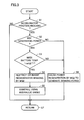
- Fig. 3 is a flowchart showing a control structure of a program related to braking of the vehicle executed by a controller 30 shown in Fig. 1 .
- the process of the flowchart is called from a prescribed main routine and executed at every prescribed time interval or every time prescribed conditions are satisfied.
- controller 30 monitors an output of accelerator sensor 9 and determines whether accelerator position decreases or not. If reduction in accelerator position is not detected, the energy balance shown in Fig. 2 is maintained and, therefore, the process proceeds to step S7 and the control returns to the main routine.
- step S2 If reduction in accelerator position is detected at step S1, the process proceeds to step S2.
- power consumption at motor generator MG2 is stopped and, therefore, controller 30 determines whether or not motor generator MG1 is generating electric power.
- a hybrid vehicle is capable of EV running in which the engine is stopped and the vehicle runs only by the motor as an electric vehicle. In EV running mode, motor generator MG1 does not generate electric power.
- step S2 if motor generator MG1 is generating power, the process proceeds to step S3, and if motor generator MG1 is not generating power, the process proceeds to step S6.
- controller 3 determines whether the battery temperature detected by temperature sensor 10 is equal to or higher than a specified temperature T1.
- the specified temperature T1 corresponds to a temperature at which input/output is restricted to protect battery B, or the temperature at which cooling is started by a cooling fan or the like, not shown.
- step S3 If the main battery temperature Tbat is equal to or higher than the specified temperature T1 at step S3, the process proceeds to step S4, and if the main battery temperature Tbat is lower than the specified temperature T1, the process proceeds to step S6.
- controller 30 restricts or inhibits power regeneration by motor generator MG2.
- controller 30 starts operation of hydraulic brake device 40 and, thereafter, the control is returned to the main routine at step S7.
- step S6 motor generator MG2 regenerates power and braking force and, thereafter, the control is returned to the main routine at step S7.
- Fig. 4 is a schematic illustration showing the energy flow at the time of running at steps S4 and S5 of Fig. 3 .
- Fig. 5 is a diagram of waveforms illustrating time-change of energy shown in Fig. 4 .
- step S4 of Fig. 3 it means that the driver has released the accelerator pedal or his/her foot is fully away from the pedal and battery temperature Tbat is equal to or higher than the specified temperature T1.
- Control response of motor generator MG2 is faster than control response of engine 200 and, therefore, if the accelerator pedal is released and the vehicle enters the accelerator-off state, it becomes unnecessary for motor generator MG2 to generate torque to be applied to the wheels and, therefore it stops power consumption.
- surplus generated power represented as Pbat (MG1)
- Pbat surplus generated power
- the hydraulic brake is operated for a prescribed time period from time t1 to t2. In this period, rotational kinetic energy Pt of the wheels is consumed as the friction heat between the disk wheel and the brake pad of the hydraulic brake. Thereafter, the operation of hydraulic brake is stopped, and the operation is switched to regenerative braking.
- start of regenerative braking using motor generator MG2 is delayed until time t2, at which the engine speed has decreased to some extent and surplus power Pbat (MG1) has reduced.
- the hydraulic brake is operated at first in response to the release of accelerator pedal, and after a delay TD, regenerative braking by MG2 starts.
- the heat generated in the battery can be reduced by a quantity corresponding to - ⁇ P.
- Fig. 6 is a schematic illustration showing the energy flow at the time of running at step S6 of Fig. 3 .
- Fig. 7 is a diagram of waveforms illustrating time-change of energy shown in Fig. 6 .
- step S6 of Fig. 3 it means that the driver has released the accelerator pedal or his/her foot is off from the pedal and the battery temperature Tbat is lower than the specified value T1.
- Control response of motor generator MG2 is faster than control response of engine 200 and, therefore, if the vehicle enters the accelerator-off state, it becomes unnecessary for motor generator MG2 to generate torque to be applied to the wheels, so that it stops power consumption.
- the vehicle drive device includes engine 200, motor generator MG1 driven by engine 200 and generating electric power, motor generator MG2 driving the vehicle and generating electric power at the time of regenerative braking, battery B capable of exchanging electric power to/from motor generators MG1 and MG2, temperature sensor 10 detecting the temperature of battery B, and controller 30 controlling motor generators MG1 and MG2.
- controller 30 switches whether motor generator MG2 is to perform regenerative braking, dependent on the output of temperature sensor 10.
- controller 30 monitors the output of accelerator sensor, and inhibits regenerative braking of motor generator MG2 for a prescribed time period (t1 to t2 of Fig. 5 ) after the reduction in required value is detected.
- controller 30 allows regenerative braking of motor generator MG2 in a prescribed period (the period of Fig. 7 corresponding to t1 to t2 of Fig. 5 ) after the reduction in required value is detected.
- the vehicle drive device further includes a brake device applying braking force to the vehicle.
- the brake device includes hydraulic brake device, brake caliper 44 and brake disk 42.
- controller 30 inhibits regenerative braking of motor generator MG2 for a prescribed time period (t1 to t2 of Fig. 5 ) and, in this period, causes the brake device to apply the braking force to the vehicle.
- the present embodiment may be described, in a different expression, as follows.
- the vehicle drive device includes engine 200, motor generator MG1 driven by engine 200 and generating electric power, motor generator MG2 driving the vehicle and generating electric power at the time of regenerative braking, battery B capable of exchanging power to/from motor generators MG1 and MG2, temperature sensor 10 detecting the temperature of battery B, and controller 30 controlling motor generators MG1 and MG2.
- controller 30 changes the timing at which motor generator MG2 starts regenerative braking, dependent on the output of temperature sensor 10.
- the vehicle drive device further includes a brake device for applying braking force to the vehicle.
- the brake device includes hydraulic brake device, brake caliper 44 and brake disk 42.
- controller 30 delays the timing of starting regenerative braking by motor generator MG2 by a prescribed period and, in the period, causes the brake device to apply the braking force to the vehicle.
- battery temperature can be maintained in a suitable range at higher ratio and, therefore, battery life is maintained and energy efficiency can be improved.
- the invention applied to a series/parallel type hybrid system has been described, in which the engine power can be split and transmitted to the axle and the generator.
- the present invention is also applicable to a series type hybrid vehicle in which only the engine is used for driving the generator and the driving force for the axle is generated only by the motor that consumes the power generated by the generator, or to an electronic vehicle that runs only by the motor.
- Application of the present invention to these structures is possible, because these structures each have the axle connected to the motor or generator, and at the time of speed reduction, capable of returning and storing regenerative energy to a battery.
Landscapes
- Engineering & Computer Science (AREA)
- Transportation (AREA)
- Mechanical Engineering (AREA)
- Power Engineering (AREA)
- Chemical & Material Sciences (AREA)
- Combustion & Propulsion (AREA)
- Automation & Control Theory (AREA)
- Life Sciences & Earth Sciences (AREA)
- Sustainable Development (AREA)
- Sustainable Energy (AREA)
- Electric Propulsion And Braking For Vehicles (AREA)
- Control Of Vehicle Engines Or Engines For Specific Uses (AREA)
Applications Claiming Priority (2)
| Application Number | Priority Date | Filing Date | Title |
|---|---|---|---|
| JP2006052845 | 2006-02-28 | ||
| PCT/JP2007/051340 WO2007099726A1 (ja) | 2006-02-28 | 2007-01-23 | 車両駆動装置および車両駆動装置の制御方法 |
Publications (2)
| Publication Number | Publication Date |
|---|---|
| EP1990231A1 true EP1990231A1 (de) | 2008-11-12 |
| EP1990231A4 EP1990231A4 (de) | 2017-09-27 |
Family
ID=38458846
Family Applications (1)
| Application Number | Title | Priority Date | Filing Date |
|---|---|---|---|
| EP07707571.1A Withdrawn EP1990231A4 (de) | 2006-02-28 | 2007-01-23 | Fahrzeugantriebsvorrichtung und verfahren zur steuerung einer fahrzeugantriebsvorrichtung |
Country Status (6)
| Country | Link |
|---|---|
| US (1) | US7923950B2 (de) |
| EP (1) | EP1990231A4 (de) |
| JP (1) | JP4321668B2 (de) |
| KR (1) | KR100981119B1 (de) |
| CN (1) | CN101395030B (de) |
| WO (1) | WO2007099726A1 (de) |
Cited By (3)
| Publication number | Priority date | Publication date | Assignee | Title |
|---|---|---|---|---|
| CN108177560A (zh) * | 2017-12-28 | 2018-06-19 | 华晨鑫源重庆汽车有限公司 | 整车控制系统 |
| WO2020048695A1 (de) * | 2018-09-04 | 2020-03-12 | Robert Bosch Gmbh | Verfahren zum betreiben eines kraftfahrzeugs, steuergerät, kraftfahrzeug |
| EP3659851A1 (de) * | 2018-11-27 | 2020-06-03 | eMining AG | Steuereinheit zur steuerung einer bremsanlage, fahrzeug mit der steuereinheit und verfahren zum betrieb des fahrzeugs |
Families Citing this family (25)
| Publication number | Priority date | Publication date | Assignee | Title |
|---|---|---|---|---|
| US8035349B2 (en) | 2008-09-30 | 2011-10-11 | Toyota Motor Engineering & Manufacturing North America, Inc. | Systems and methods for absorbing waste electricity from regenerative braking in hybridized vehicles |
| US8738260B2 (en) * | 2009-08-07 | 2014-05-27 | Toyota Jidosha Kabushiki Kaisha | Brake control system, and brake control method |
| WO2011027398A1 (ja) * | 2009-09-03 | 2011-03-10 | トヨタ自動車株式会社 | ブレーキ制御装置 |
| KR20120024001A (ko) * | 2010-09-03 | 2012-03-14 | 현대자동차주식회사 | 전기자동차의 제동 제어 방법 |
| JP5808923B2 (ja) * | 2011-03-18 | 2015-11-10 | Ntn株式会社 | モータ駆動装置及び電気自動車 |
| JP5333604B2 (ja) * | 2011-04-06 | 2013-11-06 | トヨタ自動車株式会社 | ブレーキ制御装置及びブレーキ制御方法 |
| FR2982205B1 (fr) * | 2011-11-08 | 2014-04-11 | Renault Sa | Adaptation d'une consigne de freinage moteur simulee |
| DE102012202647A1 (de) * | 2012-02-21 | 2013-08-22 | Robert Bosch Gmbh | Verfahren und Vorrichtung zur Steuerung einer elektrischen Maschine |
| JP5835095B2 (ja) * | 2012-05-16 | 2015-12-24 | トヨタ自動車株式会社 | ハイブリッド車両およびハイブリッド車両の制御方法 |
| JP5655050B2 (ja) * | 2012-10-11 | 2015-01-14 | 本田技研工業株式会社 | 発電機の制御装置 |
| WO2014158823A1 (en) | 2013-03-14 | 2014-10-02 | Allison Transmission, Inc. | System and method for optimizing hybrid vehicle battery usage constraints |
| AU2014241859B2 (en) | 2013-03-14 | 2016-04-21 | Allison Transmission, Inc. | System and method for compensation of turbo lag in hybrid vehicles |
| CA2898310C (en) | 2013-03-14 | 2022-07-12 | Allison Transmission, Inc. | System and method for power management during regeneration mode in hybrid electric vehicles |
| CN105189235B (zh) | 2013-03-14 | 2018-01-19 | 艾里逊变速箱公司 | 用于混合动力车的在再生过程中断开发动机动力传动系的系统及方法 |
| AU2014237875B2 (en) | 2013-03-15 | 2016-04-21 | Allison Transmission, Inc. | System and method for energy rate balancing in hybrid automatic transmissions |
| CA2898300C (en) | 2013-03-15 | 2020-10-27 | Allison Transmission, Inc. | Service disconnect interlock system and method for hybrid vehicles |
| EP2969640B1 (de) | 2013-03-15 | 2019-09-04 | Allison Transmission, Inc. | System und verfahren zum ausbalancieren von ladezuständen von energiespeichermodulen in hybridfahrzeugen |
| CN103887578B (zh) * | 2014-03-25 | 2016-03-30 | 东风汽车公司 | 提高电动汽车低温续航里程的动力电池加热方法和系统 |
| US10449863B2 (en) * | 2015-09-16 | 2019-10-22 | Mitsubishi Jidosha Kogyo Kabushiki Kaisha | Regenerative brake control device |
| NL2015587B1 (en) | 2015-09-28 | 2017-04-21 | Trs Transp B V | A vehicle comprising a wheel driven generator for charging a battery. |
| US10106053B2 (en) * | 2016-03-31 | 2018-10-23 | Honda Motor Co., Ltd. | Vehicle |
| US11167745B2 (en) * | 2018-04-19 | 2021-11-09 | Toyota Jidosha Kabushiki Kaisha | Control system of hybrid vehicle |
| CN110562099A (zh) * | 2019-09-23 | 2019-12-13 | 北京海纳川汽车部件股份有限公司 | 车辆的电池监控系统、方法及车辆 |
| CN112606694B (zh) * | 2020-12-25 | 2022-06-28 | 中国第一汽车股份有限公司 | 一种车辆能量回收分配方法、装置、车辆及存储介质 |
| EP4246464B1 (de) | 2022-03-16 | 2024-08-07 | Axis AB | Statische datenschutzmaskierung |
Family Cites Families (15)
| Publication number | Priority date | Publication date | Assignee | Title |
|---|---|---|---|---|
| JP2701340B2 (ja) * | 1988-07-27 | 1998-01-21 | スズキ株式会社 | 電気車の回生制動制御回路 |
| JP3047742B2 (ja) | 1994-09-02 | 2000-06-05 | トヨタ自動車株式会社 | ハイブリッド型電気自動車 |
| JP3542179B2 (ja) * | 1994-11-04 | 2004-07-14 | 本田技研工業株式会社 | 電動車両のバッテリ充電装置 |
| JP3089958B2 (ja) | 1994-12-06 | 2000-09-18 | 三菱自動車工業株式会社 | 電気自動車の制動制御装置 |
| JP3360499B2 (ja) * | 1995-09-05 | 2002-12-24 | トヨタ自動車株式会社 | 電気車両の回生制動制御装置及び方法 |
| JPH10248175A (ja) | 1997-03-06 | 1998-09-14 | J N T:Kk | 二次電池の充電方法及び充電装置 |
| US5910722A (en) * | 1997-11-21 | 1999-06-08 | Lockheed Martin Corp. | Hybrid electric vehicle with reduced auxiliary power to batteries during regenerative braking |
| US6573675B2 (en) | 2000-12-27 | 2003-06-03 | Transportation Techniques Llc | Method and apparatus for adaptive energy control of hybrid electric vehicle propulsion |
| JP4240845B2 (ja) * | 2001-05-15 | 2009-03-18 | トヨタ自動車株式会社 | ハイブリッド車 |
| JP2002095105A (ja) * | 2001-07-23 | 2002-03-29 | Hitachi Ltd | 電気自動車の回生制動制御方法および制御装置 |
| JP3689908B2 (ja) * | 2001-09-26 | 2005-08-31 | マツダ株式会社 | ハイブリッド自動車 |
| JP3876979B2 (ja) * | 2002-03-18 | 2007-02-07 | 三菱自動車工業株式会社 | バッテリ制御装置 |
| KR100534709B1 (ko) * | 2003-12-30 | 2005-12-07 | 현대자동차주식회사 | 전기자동차의 회생제동 제어 방법 및 장치 |
| JP4085996B2 (ja) | 2004-03-16 | 2008-05-14 | トヨタ自動車株式会社 | 動力出力装置およびこれを搭載する自動車並びに動力出力装置の制御方法 |
| JP4140552B2 (ja) * | 2004-04-28 | 2008-08-27 | トヨタ自動車株式会社 | 自動車用電源装置およびそれを備える自動車 |
-
2007
- 2007-01-23 WO PCT/JP2007/051340 patent/WO2007099726A1/ja active Search and Examination
- 2007-01-23 KR KR1020087023515A patent/KR100981119B1/ko not_active IP Right Cessation
- 2007-01-23 JP JP2008502674A patent/JP4321668B2/ja not_active Expired - Fee Related
- 2007-01-23 US US12/223,403 patent/US7923950B2/en not_active Expired - Fee Related
- 2007-01-23 CN CN2007800070002A patent/CN101395030B/zh not_active Expired - Fee Related
- 2007-01-23 EP EP07707571.1A patent/EP1990231A4/de not_active Withdrawn
Non-Patent Citations (1)
| Title |
|---|
| See references of WO2007099726A1 * |
Cited By (4)
| Publication number | Priority date | Publication date | Assignee | Title |
|---|---|---|---|---|
| CN108177560A (zh) * | 2017-12-28 | 2018-06-19 | 华晨鑫源重庆汽车有限公司 | 整车控制系统 |
| WO2020048695A1 (de) * | 2018-09-04 | 2020-03-12 | Robert Bosch Gmbh | Verfahren zum betreiben eines kraftfahrzeugs, steuergerät, kraftfahrzeug |
| US12122375B2 (en) | 2018-09-04 | 2024-10-22 | Robert Bosch Gmbh | Method for operating a motor vehicle, control unit, motor vehicle |
| EP3659851A1 (de) * | 2018-11-27 | 2020-06-03 | eMining AG | Steuereinheit zur steuerung einer bremsanlage, fahrzeug mit der steuereinheit und verfahren zum betrieb des fahrzeugs |
Also Published As
| Publication number | Publication date |
|---|---|
| KR100981119B1 (ko) | 2010-09-08 |
| CN101395030B (zh) | 2012-07-25 |
| JPWO2007099726A1 (ja) | 2009-07-16 |
| US20090026987A1 (en) | 2009-01-29 |
| JP4321668B2 (ja) | 2009-08-26 |
| CN101395030A (zh) | 2009-03-25 |
| EP1990231A4 (de) | 2017-09-27 |
| KR20080098439A (ko) | 2008-11-07 |
| US7923950B2 (en) | 2011-04-12 |
| WO2007099726A1 (ja) | 2007-09-07 |
Similar Documents
| Publication | Publication Date | Title |
|---|---|---|
| US7923950B2 (en) | Vehicle drive device and method of controlling vehicle drive device | |
| JP4434302B2 (ja) | ハイブリッド車両の制御装置およびハイブリッド車両 | |
| EP2559578B1 (de) | Hybridfahrzeug | |
| EP2774802A1 (de) | Fahrzeug und fahrzeugsteuerungsverfahren | |
| JP5725037B2 (ja) | 車両および車両用制御方法 | |
| US9132738B2 (en) | Electric vehicle | |
| CN100509512C (zh) | 用于驱动系统的控制器 | |
| JP5729475B2 (ja) | 車両および車両の制御方法 | |
| US9242640B2 (en) | Hybrid vehicle control device | |
| JP6620134B2 (ja) | ハイブリッド車両 | |
| JP2010058579A (ja) | ハイブリッド車両 | |
| US9067584B2 (en) | Vehicle and control method for vehicle | |
| JP2007014072A (ja) | 駆動システムの制御装置 | |
| JPH10243501A (ja) | 電気自動車のブレーキ制御装置及び充電制御装置 | |
| US9927776B2 (en) | Intentionally increasing a non-torque output of an electric machine in an electric vehicle | |
| JP2006136131A (ja) | 車両の制御装置 | |
| US20130311015A1 (en) | Vehicle and control method for vehicle | |
| JP2007215293A (ja) | 車両に搭載された二次電池の制御装置 | |
| JP7522934B2 (ja) | 車両 | |
| JP2013112320A (ja) | ハイブリッド車両 |
Legal Events
| Date | Code | Title | Description |
|---|---|---|---|
| PUAI | Public reference made under article 153(3) epc to a published international application that has entered the european phase |
Free format text: ORIGINAL CODE: 0009012 |
|
| 17P | Request for examination filed |
Effective date: 20080805 |
|
| AK | Designated contracting states |
Kind code of ref document: A1 Designated state(s): DE FR |
|
| DAX | Request for extension of the european patent (deleted) | ||
| RBV | Designated contracting states (corrected) |
Designated state(s): DE FR |
|
| RAP1 | Party data changed (applicant data changed or rights of an application transferred) |
Owner name: TOYOTA JIDOSHA KABUSHIKI KAISHA |
|
| RA4 | Supplementary search report drawn up and despatched (corrected) |
Effective date: 20170828 |
|
| RIC1 | Information provided on ipc code assigned before grant |
Ipc: B60L 11/14 20060101ALI20170822BHEP Ipc: B60L 7/16 20060101AFI20170822BHEP Ipc: B60L 7/10 20060101ALI20170822BHEP Ipc: B60L 7/14 20060101ALI20170822BHEP Ipc: H02J 7/14 20060101ALI20170822BHEP |
|
| STAA | Information on the status of an ep patent application or granted ep patent |
Free format text: STATUS: THE APPLICATION HAS BEEN WITHDRAWN |
|
| 18W | Application withdrawn |
Effective date: 20171013 |