EP1984789B1 - Beleuchtungssystem für die mikro-lithographie, projektionsbelichtungsanlage mit einem derartigen beleuchtungssystem - Google Patents
Beleuchtungssystem für die mikro-lithographie, projektionsbelichtungsanlage mit einem derartigen beleuchtungssystem Download PDFInfo
- Publication number
- EP1984789B1 EP1984789B1 EP07722838.5A EP07722838A EP1984789B1 EP 1984789 B1 EP1984789 B1 EP 1984789B1 EP 07722838 A EP07722838 A EP 07722838A EP 1984789 B1 EP1984789 B1 EP 1984789B1
- Authority
- EP
- European Patent Office
- Prior art keywords
- illumination
- raster
- intensity
- variation
- field
- Prior art date
- Legal status (The legal status is an assumption and is not a legal conclusion. Google has not performed a legal analysis and makes no representation as to the accuracy of the status listed.)
- Expired - Fee Related
Links
Images


Classifications
-
- G—PHYSICS
- G03—PHOTOGRAPHY; CINEMATOGRAPHY; ANALOGOUS TECHNIQUES USING WAVES OTHER THAN OPTICAL WAVES; ELECTROGRAPHY; HOLOGRAPHY
- G03F—PHOTOMECHANICAL PRODUCTION OF TEXTURED OR PATTERNED SURFACES, e.g. FOR PRINTING, FOR PROCESSING OF SEMICONDUCTOR DEVICES; MATERIALS THEREFOR; ORIGINALS THEREFOR; APPARATUS SPECIALLY ADAPTED THEREFOR
- G03F7/00—Photomechanical, e.g. photolithographic, production of textured or patterned surfaces, e.g. printing surfaces; Materials therefor, e.g. comprising photoresists; Apparatus specially adapted therefor
- G03F7/70—Microphotolithographic exposure; Apparatus therefor
- G03F7/70058—Mask illumination systems
- G03F7/70091—Illumination settings, i.e. intensity distribution in the pupil plane or angular distribution in the field plane; On-axis or off-axis settings, e.g. annular, dipole or quadrupole settings; Partial coherence control, i.e. sigma or numerical aperture [NA]
-
- G—PHYSICS
- G03—PHOTOGRAPHY; CINEMATOGRAPHY; ANALOGOUS TECHNIQUES USING WAVES OTHER THAN OPTICAL WAVES; ELECTROGRAPHY; HOLOGRAPHY
- G03F—PHOTOMECHANICAL PRODUCTION OF TEXTURED OR PATTERNED SURFACES, e.g. FOR PRINTING, FOR PROCESSING OF SEMICONDUCTOR DEVICES; MATERIALS THEREFOR; ORIGINALS THEREFOR; APPARATUS SPECIALLY ADAPTED THEREFOR
- G03F7/00—Photomechanical, e.g. photolithographic, production of textured or patterned surfaces, e.g. printing surfaces; Materials therefor, e.g. comprising photoresists; Apparatus specially adapted therefor
- G03F7/70—Microphotolithographic exposure; Apparatus therefor
- G03F7/70058—Mask illumination systems
- G03F7/70075—Homogenization of illumination intensity in the mask plane by using an integrator, e.g. fly's eye lens, facet mirror or glass rod, by using a diffusing optical element or by beam deflection
-
- G—PHYSICS
- G03—PHOTOGRAPHY; CINEMATOGRAPHY; ANALOGOUS TECHNIQUES USING WAVES OTHER THAN OPTICAL WAVES; ELECTROGRAPHY; HOLOGRAPHY
- G03F—PHOTOMECHANICAL PRODUCTION OF TEXTURED OR PATTERNED SURFACES, e.g. FOR PRINTING, FOR PROCESSING OF SEMICONDUCTOR DEVICES; MATERIALS THEREFOR; ORIGINALS THEREFOR; APPARATUS SPECIALLY ADAPTED THEREFOR
- G03F7/00—Photomechanical, e.g. photolithographic, production of textured or patterned surfaces, e.g. printing surfaces; Materials therefor, e.g. comprising photoresists; Apparatus specially adapted therefor
- G03F7/70—Microphotolithographic exposure; Apparatus therefor
- G03F7/70058—Mask illumination systems
- G03F7/70083—Non-homogeneous intensity distribution in the mask plane
-
- G—PHYSICS
- G03—PHOTOGRAPHY; CINEMATOGRAPHY; ANALOGOUS TECHNIQUES USING WAVES OTHER THAN OPTICAL WAVES; ELECTROGRAPHY; HOLOGRAPHY
- G03F—PHOTOMECHANICAL PRODUCTION OF TEXTURED OR PATTERNED SURFACES, e.g. FOR PRINTING, FOR PROCESSING OF SEMICONDUCTOR DEVICES; MATERIALS THEREFOR; ORIGINALS THEREFOR; APPARATUS SPECIALLY ADAPTED THEREFOR
- G03F7/00—Photomechanical, e.g. photolithographic, production of textured or patterned surfaces, e.g. printing surfaces; Materials therefor, e.g. comprising photoresists; Apparatus specially adapted therefor
- G03F7/70—Microphotolithographic exposure; Apparatus therefor
- G03F7/70058—Mask illumination systems
- G03F7/70091—Illumination settings, i.e. intensity distribution in the pupil plane or angular distribution in the field plane; On-axis or off-axis settings, e.g. annular, dipole or quadrupole settings; Partial coherence control, i.e. sigma or numerical aperture [NA]
- G03F7/70108—Off-axis setting using a light-guiding element, e.g. diffractive optical elements [DOEs] or light guides
-
- G—PHYSICS
- G03—PHOTOGRAPHY; CINEMATOGRAPHY; ANALOGOUS TECHNIQUES USING WAVES OTHER THAN OPTICAL WAVES; ELECTROGRAPHY; HOLOGRAPHY
- G03F—PHOTOMECHANICAL PRODUCTION OF TEXTURED OR PATTERNED SURFACES, e.g. FOR PRINTING, FOR PROCESSING OF SEMICONDUCTOR DEVICES; MATERIALS THEREFOR; ORIGINALS THEREFOR; APPARATUS SPECIALLY ADAPTED THEREFOR
- G03F7/00—Photomechanical, e.g. photolithographic, production of textured or patterned surfaces, e.g. printing surfaces; Materials therefor, e.g. comprising photoresists; Apparatus specially adapted therefor
- G03F7/70—Microphotolithographic exposure; Apparatus therefor
- G03F7/70058—Mask illumination systems
- G03F7/70191—Optical correction elements, filters or phase plates for controlling intensity, wavelength, polarisation, phase or the like
-
- G—PHYSICS
- G03—PHOTOGRAPHY; CINEMATOGRAPHY; ANALOGOUS TECHNIQUES USING WAVES OTHER THAN OPTICAL WAVES; ELECTROGRAPHY; HOLOGRAPHY
- G03F—PHOTOMECHANICAL PRODUCTION OF TEXTURED OR PATTERNED SURFACES, e.g. FOR PRINTING, FOR PROCESSING OF SEMICONDUCTOR DEVICES; MATERIALS THEREFOR; ORIGINALS THEREFOR; APPARATUS SPECIALLY ADAPTED THEREFOR
- G03F7/00—Photomechanical, e.g. photolithographic, production of textured or patterned surfaces, e.g. printing surfaces; Materials therefor, e.g. comprising photoresists; Apparatus specially adapted therefor
- G03F7/70—Microphotolithographic exposure; Apparatus therefor
- G03F7/70058—Mask illumination systems
- G03F7/70208—Multiple illumination paths, e.g. radiation distribution devices, microlens illumination systems, multiplexers or demultiplexers for single or multiple projection systems
-
- G—PHYSICS
- G03—PHOTOGRAPHY; CINEMATOGRAPHY; ANALOGOUS TECHNIQUES USING WAVES OTHER THAN OPTICAL WAVES; ELECTROGRAPHY; HOLOGRAPHY
- G03F—PHOTOMECHANICAL PRODUCTION OF TEXTURED OR PATTERNED SURFACES, e.g. FOR PRINTING, FOR PROCESSING OF SEMICONDUCTOR DEVICES; MATERIALS THEREFOR; ORIGINALS THEREFOR; APPARATUS SPECIALLY ADAPTED THEREFOR
- G03F7/00—Photomechanical, e.g. photolithographic, production of textured or patterned surfaces, e.g. printing surfaces; Materials therefor, e.g. comprising photoresists; Apparatus specially adapted therefor
- G03F7/70—Microphotolithographic exposure; Apparatus therefor
- G03F7/70383—Direct write, i.e. pattern is written directly without the use of a mask by one or multiple beams
- G03F7/704—Scanned exposure beam, e.g. raster-, rotary- and vector scanning
-
- G—PHYSICS
- G03—PHOTOGRAPHY; CINEMATOGRAPHY; ANALOGOUS TECHNIQUES USING WAVES OTHER THAN OPTICAL WAVES; ELECTROGRAPHY; HOLOGRAPHY
- G03F—PHOTOMECHANICAL PRODUCTION OF TEXTURED OR PATTERNED SURFACES, e.g. FOR PRINTING, FOR PROCESSING OF SEMICONDUCTOR DEVICES; MATERIALS THEREFOR; ORIGINALS THEREFOR; APPARATUS SPECIALLY ADAPTED THEREFOR
- G03F7/00—Photomechanical, e.g. photolithographic, production of textured or patterned surfaces, e.g. printing surfaces; Materials therefor, e.g. comprising photoresists; Apparatus specially adapted therefor
- G03F7/70—Microphotolithographic exposure; Apparatus therefor
- G03F7/70483—Information management; Active and passive control; Testing; Wafer monitoring, e.g. pattern monitoring
- G03F7/7055—Exposure light control in all parts of the microlithographic apparatus, e.g. pulse length control or light interruption
Definitions
- the invention relates to a lighting system for micro-lithography for illuminating a lighting field with illumination light. Furthermore, the invention relates to a microlithography projection exposure apparatus with such a lighting system. Furthermore, the invention relates to a microlithographic manufacturing method for microstructured components. Finally, the invention relates to a device produced by such a method.
- the EP 1367 442 A2 shows an illumination system, which is used to illuminate a lighting field in a mask plane with illumination light.
- Part of the lighting system is a grid module with two grid arrangements (Fly's Eye Members).
- the raster module serves to generate secondary light sources.
- a transfer optics serves to transfer the illumination light from the raster module into the illumination field.
- Correction filters 15, 16 are used to correct for uneveness of illumination (Uneveness in Illumination).
- a microscope illumination in which a microlens array is used.
- a step mirror is arranged for coherence reduction, which influences a phase of the illumination light differently for different raster elements of the microlens array.
- the US 2002/0136351 A1 shows an illumination system with two raster arrangements, wherein raster elements of these raster arrangements on the one hand have a refractive and on the other hand a prismatic effect, which is indicated figuratively schematically.
- a cylindrical lens array is known for homogenizing light.
- an additionally optically acting device provided in the region of the first raster arrangement and influencing the illumination light such that the intensity contribution of raster channels of the first raster arrangement to the overall illumination intensity varies over the illumination field provides additional degrees of freedom in the design of the field-dependent optical effect of the illumination system supplies.
- Field-dependent optical effects of other components of the illumination system or of the projection optics can be corrected or compensated with the aid of the additionally optically acting device according to the invention.
- the correctable or compensable effects include, for example, transmission variations of optical components across their diameters. Such transmission variations can for example be precompensated or overcompensated by the optical device additionally acting according to the invention.
- a possible beam direction influencing by the additionally optically acting device is in particular such that not the entire illumination light beam is influenced in the same way in its beam direction, that is deflected, but that certain partial light beams of the illumination light are deflected defined, weakened or phase-influenced, while other partial Light bundles are not deflected or otherwise deflected, weakened or phase-influenced.
- a spatially adjacent assignment of the additionally optically acting device to the first grid arrangement is given in a variant of the illumination system in that the additionally optically acting device is designed as a separate component to the first grid arrangement, which is present in the immediate vicinity of the grid arrangement.
- the spatially adjacent additionally optically acting device can be in direct contact with the first or another grid arrangement and, for example, be designed as a coating on at least one of the grid arrangements.
- the raster elements of the first raster arrangement and at least one possible further raster arrangement are preferably refractive.
- the first grid arrangement does not necessarily have to be monolithic, ie integral, on a substrate. It is also possible that the first raster arrangement is formed in two pieces, wherein the first raster lines are formed on a first substrate and the first raster columns on a second substrate.
- a distance between these two substrates may exist such that the additionally optically acting device is arranged in the immediate vicinity in front of the first plane in which the two-dimensional intensity distribution of the illumination light is predetermined is.
- this first level is a pupil plane of the illumination system.
- the field dependence of the intensity contributions can then be used selectively to desired intensity peaks for selected illumination angles at specific field points, for increasing the intensity of the overall illumination intensity at specific field points or for a combination of the two. In particular, this can also serve compensation purposes to compensate for field-dependent impacting transmission losses in the illumination or the projection optics.
- the illumination system may include a light or radiation source adapted to an illumination optics of the illumination system; but this is not mandatory.
- the illumination system can therefore also be exclusively optical components which are arranged downstream of a correspondingly adapted light or radiation source which is provided separately.
- the illumination system has an illumination angle variation device arranged in the light path adjacent to the first raster arrangement or in a plane which is optically conjugate to a plane in which the first raster arrangement is arranged as the additionally optically acting device.
- This illumination angle variation device deflects illumination light incident on the illumination angle variation device in at least two angular variation sections perpendicular to the optical axis with different deflection angles.
- a maximum deflection angle generated by the illumination angle variation device is so large that an intensity contribution of raster elements of the first raster arrangement to the overall illumination intensity varies across the illumination field.
- an otherwise disturbing aberration namely the nonlinearity of the refraction at high angles of incidence
- the illumination angle variation device is set to specific deflection angle, wherein at least at the maximum deflection angles that can be adjusted, the paraxial approximation in the refraction of the raster elements of the first grid arrangement is no longer valid. This inevitably leads to field-dependent intensity contributions of the raster elements, which are subjected to deflection angles beyond the validity of the paraxial approximation.
- the light distribution device for generating a predetermined two-dimensional intensity distribution from the illumination light in the first plane perpendicular to the optical axis of the illumination system provides for a defined two-dimensional intensity distribution in the first plane.
- the light distribution device is referred to as a pupil-defining element (PDE).
- PDE pupil-defining element
- the light distribution device can be dispensed with if a predetermined intensity distribution in the first plane or in a plane optically conjugated thereto can also be predetermined by other means. This is the case, for example, if the predetermined intensity distribution is generated by the first raster arrangement itself or by the combined optical effect of the first raster arrangement with at least one possible further raster arrangement.
- a second raster arrangement forms with the first raster arrangement a raster module, which specifies in particular the shape and the illumination of the illumination field and is therefore designated as field-defining element (FDE).
- the second raster arrangement can be dispensed with in particular in cases in which a defined drop or increase in the illumination intensity occurs at a portion of the illumination field leading or following in a scanning direction in which an object is guided through the illumination field is desired.
- the first raster arrangement can have an effect collecting the illumination light, wherein the second raster arrangement can be arranged in a focal plane of the first raster arrangement.
- this arrangement of the second grid arrangement is not mandatory.
- An illumination angle variation device leads to the above-mentioned combination of field-dependent intensity contributions from predetermined illumination directions and at the same time to a field-dependent overall illumination intensity. In this case, several available degrees of freedom of the field-dependent intensity distribution are used.
- An illumination angle variation device aims at a field-dependent overall illumination intensity, wherein there is no illumination angle dependence of the intensity across the field. This can be used in particular for loss compensation.
- An illumination angle variation device has field-dependent intensity contributions from the different illumination directions, but no field dependence of the overall illumination intensity. Individual field points would therefore be irradiated in total with the same overall intensity, but from different centroid directions. This can be used to image structures with preferential directions distributed over the illumination field.
- Lighting angle variation devices according to claims 6 and 7 provide degrees of freedom, which are matched to the respective projection application, with regard to the generated deflection angles.
- optically acting devices according to claims 8 and 9 can be produced with micro-optical techniques. As far as the additionally optically acting device is designed as a variation coating, this can be fine influenced by ion beam processing (Ion Beam figuring (IBF)) with respect to their layer thickness distribution over the entire aperture of the raster module. A hybrid embodiment of the illumination angle variation device is also possible.
- IBF ion Beam figuring
- An illumination angle varying device according to claim 10 can be produced with high precision.
- the additionally optically acting device can be designed as a grid arrangement, wherein the screening of the additionally optically acting device corresponds to the screening of the first grid arrangement.
- Such an additionally optically acting device allows a fine adaptation to a desired field-dependent illumination intensity distribution.
- a distance of the illumination angle variation device to the first raster arrangement may be smaller than the quotient of a raster width of the first raster arrangement and the maximum deflection angle.
- Such a configuration of the illumination angle variation device ensures that the first raster elements are subjected to deflected illumination light.
- Individual raster elements of the illumination angle variation device can be designed as wedge elements. Such wedge elements can be produced with a precisely predetermined wedge angle.
- Individual raster elements of the illumination angle variation device can be embodied as inverse roof edge prisms.
- Such inverse roof edge prisms lead to a field dependence of the illumination intensity, which increases the edges of the apertures of the optics in intensity. This can be used to compensate for edge losses in the illumination or projection optics.
- the illumination angle variation device as a whole or individual raster elements of the illumination angle variation device can have a refracting conical surface, wherein a rotational symmetry axis of the conical surface coincides with or is parallel to the optical axis.
- Variation filter elements according to aspect 45 allow a high variation bandwidth with respect to the illumination field-dependent optical effect of the illumination system.
- Another object of the invention is a microlithography projection exposure apparatus with an illumination system according to the invention to provide as well as a hereby feasible microlithographic manufacturing process.
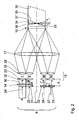
- FIG. 1 schematically shows a microlithography projection exposure apparatus 1, which is designed as a wafer scanner and is used in the manufacture of semiconductor devices and other finely structured components.
- the projection exposure apparatus 1 works to achieve resolutions down to fractions of a micron with light, in particular from the deep ultraviolet region (VUV).
- a scanning direction of the projection exposure apparatus 1 runs perpendicular to the plane of the drawing Fig. 1 and 2 , I'm in the FIG. 1 shown meridional section all optical components of the projection exposure system 1 along an optical axis 2 are lined up. It is understood that any folds of the optical axis 2 are possible, in particular to make the projection exposure system 1 compact.
- a defined illumination of an object or illumination field 3 in a reticle plane 4 in which a structure to be transferred is arranged in the form of a reticle, not shown serves a generally designated 5 lighting system of the projection exposure system 1.
- primary light source 6 is an F 2 Laser with a working wavelength of 157 nm, whose illumination light beam is aligned coaxially to the optical axis 2.
- Other UV light sources such as an ArF excimer laser with 193 nm operating wavelength, a Krf excimer laser with 248 nm working wavelength and primary light sources with larger or smaller operating wavelengths are also possible.
- the light beam coming from the light source 6 with a small rectangular cross section initially encounters a beam widening optical system 7, which generates an emergent beam 8 with substantially parallel light and a larger rectangular cross section.
- the beam expansion optics 7 may include elements that serve to reduce the coherence of the illumination light.
- the laser light, which is largely parallelized by the beam widening optics 7, then strikes a diffractive optical element (DOE) 9, which is designed as a computer-generated hologram for generating an illumination light angle distribution.
- DOE diffractive optical element
- the angular distribution produced by the DOE 9 is converted into a two-dimensional, ie perpendicular to the optical axis 2 location-dependent illumination light intensity distribution when passing through a Fourier lens assembly or a condenser 10, which is positioned at a distance of its focal length from the DOE.
- the intensity distribution thus generated is therefore present in a first illumination plane 11 of the illumination system 5.
- the DOE 9 thus represents a light distribution device for generating a two-dimensional illumination light intensity distribution.
- a first raster arrangement 12 of a raster module 13 is arranged, which is also referred to as a honeycomb condenser.
- the raster module 13 together with an illumination angle variation device 14 arranged in front of it in the light path, serves to generate a defined intensity and illumination angle distribution of the illumination light.
- the illumination angle varying means 14 represents a first example of an optically acting device which includes the Intensity, the phase or the deflection angle of the illumination light beam 8 influenced. The optical effect of the illumination angle variation device 14 will be explained in more detail below with reference to various embodiments.
- a second raster arrangement 16 is arranged in a further illumination plane 15, which is a Fourier-transformed plane to the illumination plane 11, a second raster arrangement 16 is arranged.
- the two grid arrangements 12, 16 represent the honeycomb condenser 13 of the illumination system 5.
- the further illumination plane 15 is a pupil plane of the illumination system 5.
- a further condenser 17 Downstream of the raster module 13 is a further condenser 17, which is also referred to as field lens. Together with the second raster arrangement 16, the condenser 17 forms the illumination plane 11 in a field intermediate plane 18 of the illumination system 5.
- a reticle masking system (REMA) 19 may be arranged, which serves as an adjustable shading diaphragm for generating a sharp edge of the illumination light intensity distribution.
- a subsequent objective 20 images the field intermediate plane 18 onto the reticle, that is to say the lithography original, which is located in the reticle plane 4.
- the reticle plane 4 on a wafer plane 22 on the in FIG. 1 Wafer is moved intermittently or continuously in the scan direction.
- the illumination angle variable device 14 is designed to be diffractive.
- the first raster arrangement 12 has individual first raster elements 23 which are arranged in rows and columns.
- the first raster elements 23 have a rectangular aperture with an x / y aspect ratio (y: scan direction) of, for example, 2/1.
- y scan direction
- Other, in particular larger aspect ratios of the first raster elements 23 are possible.
- the meridional section after FIG. 1 goes along a grid column.
- the first raster elements 23 are in particular as microlenses, z. B. with positive refractive power formed.
- the rectangular shape of the first latching elements 23 corresponds to the rectangular shape of the illumination field 3.
- the first latching elements 23 are arranged directly adjacent to one another in a grid corresponding to their rectangular shape, that is to say they are substantially flat.
- the first locking elements 23 are also referred to as field honeycombs.
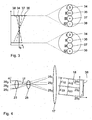
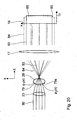
- FIG. 2 shows by way of example four first raster elements 23 which predetermine channels I to IV for illumination light bundles 24 to 27 of the illumination light 8 from top to bottom.
- the illumination light beam 24 is assigned to the channel I, the illumination light beam 25 to the channel II, the illumination light beam 26 to the channel III and the illumination light beam 27 to the channel IV.
- the real raster module 13 is a significantly higher number of channels, z. B. some hundreds of such channels.
- second latching elements 28 of the second raster arrangement 16 are arranged, in each case assigned to the channels.
- the second latching elements 28 are likewise designed as microlenses with, in particular, positive refractive power.
- the second latching elements 28 are also referred to as pupil honeycombs which are arranged in the illumination plane 15, that is to say in a pupil plane of the illumination system 5.
- the illumination plane 15 is conjugate to a pupil plane 29 of the projection lens 21.
- the images of the first locking elements 23 are superimposed in the field intermediate plane 18.
- the illumination angle variation device 14 arranged in the light path in front of the first latching arrangement 12 is subdivided into angle variation sections, wherein each angle variation section is assigned to a channel of the latching module 13.
- An angle variation section 30 is assigned to the channel I, an angle variation section 31 to the channel II, an angle variation section 32 to the channel III and an angle variation section 33 to the channel IV.
- the extent of each angle variation section 30 to 33 perpendicular to the optical axis 2 corresponds to the rectangular aperture of the channels I to IV.
- the illumination angle variation device 14 therefore likewise represents a raster arrangement.
- Each angle variation section 30 to 33 has an aperture which corresponds to the aperture of the associated first raster element 23.
- the angle variation section 30 is designed as a plane-parallel latching element, so that it does not deflect the incident illuminating light beam 24. Assuming that the illumination light beam 24 illuminates the entire aperture of the channel I with the same intensity, an intensity contribution 34 of the first channel I results in the field intermediate plane 18, which constantly has a value I 0 via an illumination field 35 in the field intermediate plane 18.
- the angle variation portion 31 of the illumination angle varying means 14 associated with the channel II is shown in FIG Fig. 2 downwardly tapering wedge formed with a first wedge angle ⁇ between an entrance and an exit surface.
- the illumination light bundle 25 guided parallel to the optical axis 2 in front of the illumination angle variation device 14 in the Fig. 2 deflected by an angle ⁇ 'upwards.
- the illumination light beam 25 which is shown in dashed lines, divided into three illumination sub-beams 25 1 , 25 2 and 25 3 , incidentally numbered from bottom to top divided.
- the Fig. 4 is drawn through for comparison also divided into three illumination sub-beams and parallel to the optical axis 2 in the channel II incident illumination light beam.
- the illumination sub-beam 25 3 on the first latching element 23 is broken most.
- the paraxial approximation is no longer valid. Therefore, the illumination sub-beam 25 is too much broken compared to an aberration-free image, ie deflected by an angle ⁇ '.
- the two other illumination sub-beams 25 2 and 25 1 are broken only relatively small, so there is still the paraxial approximation.
- the angle variation portion 32 of the illumination angle varying means 14 associated with the channel III has an exit side wedge angle ⁇ smaller than the wedge angle ⁇ .
- the angle variation section 32 tapers in the Fig. 2 wedge-shaped down.
- a deflection angle ⁇ 'experienced by the illumination light beam 26 through the angle variation portion 32 is smaller than the deflection angle ⁇ ' generated by the angle variation portion 31.
- a smaller difference results in the distances between the two peripheral illumination sub-beams and the central illumination sub-beam in the channel III, so that an intensity contribution 37 of the channel III results, via the illumination field 35 in the Fig. 2 from top to bottom linear decreases with less slope than the intensity contribution 36 of the channel II.
- the maximum intensity of the intensity contribution 37 at the upper edge of the illumination field 35 is less than the maximum intensity of the intensity contribution 36.
- the minimum intensity of the intensity contribution 37 of the channel III is greater than the minimum intensity of the intensity contribution 36 of the channel II.
- the angular variation portion 33 of the channel IV is considered to be in the Fig. 2 upwardly tapering wedge formed with a wedge angle ⁇ between the inlet and outlet surface, which corresponds in its absolute value to the wedge angle ⁇ of the angular variation portion 32 of the channel III.
- the result is a linearly varying over the illumination field intensity contribution 38 of the channel IV, which corresponds to the intensity contribution 37, mirrored about the optical axis 2.
- the minimum intensity is therefore in the Fig. 2 upper field margin and the maximum intensity at the in the Fig. 2 lower edge of field.
- the field edge-side minimum and maximum intensities of the intensity contributions 37 and 38 are approximately equal in absolute value.
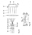
- Fig. 3 illustrates the effect of the illumination angle varying means 14 on the illumination field 35.
- the intensity contributions 34 and 36-38 of the channels I-IV are shown.
- the channel I makes an intensity contribution Io, which is represented by "0".
- the intensity of the intensity contribution 36 is maximal at the upper edge of the illumination field 35, which is illustrated by "++".
- the intensity of the intensity contribution 37 of the channel III is also at the upper field edge also maximum, but less than that of the intensity contribution 36 of the channel II, which is illustrated by "+”.
- the intensity of the intensity contribution 38 of the channel IV is lowest at the upper edge of the field, which is illustrated by "-".
- the intensity of the intensity contribution 34 of the channel I is also there I 0 , which is indicated by "0".
- the intensity of the intensity contribution 36 of channel II has the absolute minimum there, which is indicated by "- -”.
- the intensity of the intensity contribution 37 of channel III also has an absolute minimum at the lower edge of the field. However, this minimum intensity of the intensity contribution 37 is greater than the minimum intensity of the intensity contribution 36, so that the minimum intensity of the channel III at the lower field edge is indicated by "-”.
- the intensity contribution 38 of the channel IV has at the lower edge of the field a maximum whose absolute value corresponds to the maximum of the intensity contribution 37 at the upper edge of the field. The intensity contribution of the channel IV at the lower edge of the field is thus indicated by a "+".
- At the lower field edge of the illumination field 35 is thus an intensity composition in which the intensity contribution 38 of the channel IV is strongest, followed by the intensity contribution 34 of the channel I, the intensity contribution 37 of the channel III and the intensity contribution 36 of the channel II.
- the intensity compositions of the different intensity contributions from the possible illumination directions are thus different at the upper field edge and at the lower field edge.
- Corresponding intensity compositions of the intensity contributions from the possible illumination directions result for field points between the upper and the lower edge of the illumination field 35.
- the differences in the intensity contributions 36, 37 and 38 to the intensity I 0 of the Intensity contribution 34 In the middle between the edges of the illumination field 35, all channels I-IV with the same intensity I 0 contribute to the total illumination intensity at the respective field point.
- All field points of the illumination field 35 are thus illuminated from all channels I-IV, but with different intensity contributions from the possible illumination directions.
- the distance A of the illumination angle variation device 14 to the first raster arrangement 12 is smaller than the quotient of the raster width R of the first raster element 12 and the maximum deflection angle ⁇ '. With a corresponding illumination of the angle variation sections 30 to 33 by the illumination light bundles 24 to 27, this ensures that virtually the entire illumination light bundle 24 to 27 reaches the associated raster element 23 of the first raster arrangement 12 despite the deflection by the illumination angle variation device 14.
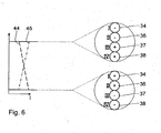
- FIG Fig. 5 A further embodiment of an illumination angle variation device which can be used instead of the illumination angle variation device 14 is shown in FIG Fig. 5 shown. This embodiment is described below with reference to Fig. 5 and 6 described. Components which correspond to those described above with reference to the Fig. 2 to 4 have the same reference numbers and will not be explained again in detail.
- the illumination angle varying means 40 is designed as a roof edge prism with a roof edge 41 which intersects the optical axis 2 and perpendicular to the plane of the Fig. 5 lies.
- the illumination angle variation device 40 has only two angular variation sections 42, 43, namely a wedge-shaped tapering upwards Angle variation section 42 in FIG Fig. 5 above the roof edge 41 and a wedge-shaped downwardly tapering angle variation section 43 in FIG Fig. 5 below the roof edge 41.
- This shape of the illumination angle varying means 40 results for the channels I and II by the angle variation portion 42 a deflection by an angle ⁇ 'down and leads the channels III and IV by the angle variation portion 43 a deflection by an angle ⁇ 'upwards.
- This deflection angle ⁇ ' corresponds to the absolute value of the deflection angle ⁇ ', the angle variation sections 32, 33 of the illumination angle varying means 14 after Fig. 2 produce.
- Intensity contributions 44 of the channels I and II are virtually identical and correspond to the course of the intensity contribution 38 of the embodiment according to their profile via the illumination field 35 Fig. 2
- Intensity contributions 45 of the channels III and IV are practically identical and correspond in their course to the intensity contribution 37 according to the embodiment Fig. 2 ,
- the upper edge of the illumination field 35 is subjected to minimum intensity by channels I and II and maximum intensity channels III and IV in the embodiment with illumination angle variation device 40.
- the lower edge of the illumination field 35 is acted upon by channels I and II with maximum intensity and by channels III and IV with minimal intensity.
- the intensity difference between the intensity contributions of the channels I and II on the one hand and the intensity contributions of the channels III and IV on the other hand reduces linearly, until in the middle of the field all channels I to IV contribute with equal intensities to the total intensity.
- the absolute value of the wedge angle ⁇ 'of the angle variation sections 42, 43 is the same, the absolute value of the slope of the intensity contributions 44, 45 across the illumination field 35 is also equal. Assuming that the channels I to IV carry the same light intensities in the illumination angle variation unit 40, this results in a total intensity distribution 46 which is constant over the entire illumination field 35, ie, independent of the field. However, different illumination field points are also illuminated in the illumination angle variation device 40 with different intensity contributions, namely corresponding to the intensity contributions 44, 45 from the possible illumination directions, ie from the direction of the channels I to IV. However, the linear intensity contributions 44, 45 differently inclined over the illumination field 35 cancel each other out exactly in the overall intensity view, so that the overall intensity distribution, but not the angular distribution, is field-independent.
- the illumination angle variation device 14 may also be designed as a refracting conical surface whose cross-section corresponds to that in the Fig. 5 is shown. It then results perpendicular to the plane of the Fig. 5 an intensity profile with intensity contributions 44, 45 corresponding to what is in the Fig. 5 is shown.
- Angle variation sections with wedge angle corresponding to the angle variation sections 42, 43 can also be produced by wedge steps comparable to a Fresnel lens such that the total thickness of the illumination angle variation device remains constant on average in a plane perpendicular to the optical axis 2.
- This variant of the illumination angle variation device 40 then has a grid of angle variation subsections each with the same wedge angle on the angle variation sections 42, 43.
- Fig. 7 shows a further embodiment of a raster module with an illumination angle variation device 47, which can be used instead of the illumination angle variation device 14.
- Components which correspond to those described above with reference to the Fig. 5 and 6 have the same reference numbers and will not be discussed again in detail.
- the embodiment of the illumination angle variation device 47 is explained by way of example with reference to an upper channel I and a lower channel II of the raster module 13.
- the illumination angle variation device 47 is designed as a raster arrangement of angular variation sections 48, the screening of which corresponds to that of the first raster arrangement 12.
- the aperture of the angle variation section 48 therefore corresponds to the aperture of a first raster element 23.
- Each angle variation section 48 is embodied as an inverse roof prism with a roof edge 49 which is arranged centrally between the edges of each angle variation section 48 in the exit surface and perpendicular to the plane of the drawing Fig. 7 stands. In the Fig. 7 Above the roof edges 49, an upwardly wedge-shaped widening first angle variation subsection is formed. Below each roof edge 49 is a in the Fig. 7 downwardly wedge-shaped widening second angular variation subsection 51 is formed.
- angle variation portions 48 of the channels I and 11 meet illumination light beams 52, 53, which in the Fig. 7 are divided into a solid upper illumination sub-beams 52 ', 53' and Dashed into a lower illumination sub-beam 52 ", 53".
- the upper illuminating sub-beams 52 ', 53' are deflected downward by the first angular variation subsections 50 by an angle ⁇ 'and the lower illuminating sub-beams 52 ", 53” are deflected by the angular variation subsections 51 by an angle ⁇ ' ,
- Each angle variation section 48 contributes to the illumination intensity in the illumination field 35 with an intensity contribution 54 that is the same in its dependence on the illumination field 35.
- the intensity distribution 54 thus has a shape that corresponds to the cross section of a single angle variation section 48.
- the angle variation sections can also be designed as raster elements with a refracting conical surface.
- a rotational symmetry axis of the respective conical surface is parallel to the optical axis 2 or coincides therewith.
- the total intensity therefore increases linearly in this variant from a minimum in the middle of the illumination field 35 towards the edge.
- the illumination light intensity distributions produced by the illumination angle variation devices 14, 40 and 47 in the illumination field 35 in the field intermediate plane 18 are imaged with the imaging scale of the objective 20 into the illumination field 3 in the reticle plane 4.
- Variants of the illumination angle variation devices that are not shown can be refractive or hybrid.
- At least part of the reticle is imaged onto a region of a photosensitive layer on the wafer or substrate for the microlithographic production of a microstructured component.
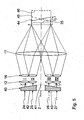
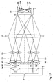
- Fig. 8 shows a variant of the microlithography projection exposure apparatus 1, which differs from that according to Fig. 1 differs only in the structure of the raster arrangement 12 and in the arrangement of the illumination angle variation device 14 relative to the raster arrangement 12 and to the first illumination plane 11.
- the first raster arrangement 12 subdivided into a column arrangement 12 'with raster elements which form the first raster columns, and into a line arrangement 12 " with raster elements that form the first raster lines.
- the illumination angle varying device 14 is arranged between the column arrangement 12 'and the line arrangement 12 "in the region of the first illumination plane 11.
- the column arrangement 12 ' is just in front
- the distance between the column arrangement 12' and the line arrangement 12" to the illumination plane 11 is so small that it is in terms of optical effect of these two arrangements 12 ', 12 "is not significant.
- column array 12 'and row array 12 may also be reversed.
- the second raster order 16 is divided into a row arrangement and a column arrangement.
- Fig. 9 shows a raster module 13 with a further variant of an optically acting device for influencing intensity contributions of the raster elements 23, 28 to the overall illumination intensity over the illumination field 35.
- Components and reference variables which correspond to those the above already with reference to the Fig. 1 to 8 have the same reference numbers and will not be discussed again in detail.
- the optically acting device for influencing the properties of the illumination light beam 8 is formed as an optical variation coating 55 on the second raster elements 28 of the second raster arrangement 16.
- the variation coating 55 is applied to the side of the second raster arrangement 16 facing the first raster arrangement 12.
- Each of the second raster elements 28 carries an individual transmission coating.
- the transmission coatings are designed, for example, as interference layers.
- the thickness of the respective transmission coating can be finely influenced by ion beam processing (IBF).
- IBF ion beam processing
- the illumination light beam 27 of the channel IV is bundled by the first raster element 23 of the channel IV in the direction of the second raster element 28 of the channel IV.
- a central ray 57 of the illumination light beam 27 is not deflected by the first raster element 23 and therefore strikes the transmission coating 56 and the second raster element 28 perpendicularly.
- a particle ⁇ 1 between the central ray 57 and a tangent to the point of impact of the central ray 57 on the Transmission coating 56 is therefore 90 °.
- the angle between an edge beam 58 of the illumination light beam 27 and a tangent to the point of impact of this edge beam 58 on the transmission coating 56, ⁇ 2 is less than 90 °. Therefore, the effective optical path of the central ray 57 through the transmission coating 56 is smaller than the effective path of the marginal ray 58 through the transmission coating 56.
- the transmission coating 56 thus has a different transmissive effect for peripheral rays of the illumination light beam 27 than for the central ray 57 Illuminating light bundle 27 thus experiences a transmission dependent on the location of incidence on the second raster element 28.
- the transmission coating 56 has the same layer thickness on the entire second grid element 28. This consistency of the layer thickness over the respective second raster element 28 applies to the entire variation coating 55, wherein the layer thicknesses of the transmission coatings for the individual second raster elements 28 may differ from one another.
- the thickness of the transmission coating 56 is selected such that the transmission of the transmission coating 56 for the central beam 57 is less than for the marginal rays 58.
- An intensity contribution 59 of the channel IV over the illumination field 35 in the field intermediate plane 18 is shown in FIG Fig. 9 shown in dashed lines. In the center of the illumination field 35, the intensity contribution 59 is the lowest. Towards the edge of the illumination field 35, the intensity contribution 59 increases continuously and reaches the highest value I 0 at the edge of the illumination field 35.
- FIG Fig. 9 The effect of a transmission coating 60 on the second raster element 28 of the channel III is shown in FIG Fig. 9 represented by an intensity contribution 61 via the illumination field 35.
- the intensity contribution 61 is in the Fig. 9 shown in phantom.
- the transmission coating 60 of the channel III has an impact on the second raster element 28 of the channel III dependent effect that corresponds to that of the transmission coating 56.
- the central ray of the illumination light bundle 26 is not so much weakened, so that the absolute variation of the intensity in the intensity contribution 61 is lower.
- the marginal rays 58 of the channel III are in turn transmitted with an intensity I 0 .
- the effect of a transmission coating 62 on the second raster element 28 of the channel II is in the Fig. 9 represented by an intensity contribution 63 via the illumination field 35.
- the transmission coating 62 is designed so that the illumination light beam 25 is transmitted regardless of its impact on the transmission coating 62 with the same intensity.
- the intensity contribution 63 is in each case I 0 , regardless of the location on the illumination field 35.
- a transmission coating 56 corresponding to the transmission coating 56 of the channel IV is again applied to the second screen element 28.
- the illumination light beam 24 is followed by the raster module 13 Fig. 9 as well as the illumination light beam 27, so that the illumination light beam 24 also provides an intensity contribution corresponding to the intensity contribution 59 via the illumination field 35.
- the differences in the transmissive effect of the transmission coatings 56, 60 and 62 can be achieved by different layer thicknesses of the transmission coatings or by different materials used for these transmission coatings. Differences can also be achieved by different material sequences of the transmission coatings, which are usually multilayered.
- Fig. 11 schematically shows a plan view of the second grid assembly 16 of the raster module 13 after Fig. 9
- Opposing edge strips 64 of the second raster arrangement 16 are carried out with second raster elements 28, respectively transmission coatings with the optical effect of the transmission coating 56 of the channels I, IV Fig. 9 wear.
- Each of the edge strips 64 in this case has a plurality of second raster elements 28, that is to say a plurality of channels.
- the two edge strips 64 generate an intensity contribution via the illumination field 35 which follows the intensity contribution 59 Fig. 9 , multiplied by the number of channels in the edge strips 64, corresponds, as in the Fig. 11 indicated.
- the two edge strips 64 extend along a scanning direction y of the projection exposure apparatus 1.
- a central strip 65 which extends between the two edge strips 64, has second raster elements 28 whose transmission coatings reflect the optical effect of the transmission coating 62 of the channel 11 in FIG Fig. 9 to have.
- the central strip 65 is more than twice as wide as the marginal strips 64.
- the central strip 65 contributes with intensity contributions to the overall intensity in the illumination field 35 multiplied by the number of channels in the central strip 65, the intensity contribution 63 correspond, as in the Fig. 11 indicated.
- the width of the intermediate strips 66 which also run parallel to the scanning direction y, is less than the width of the edge strips 64.
- the two intermediate strips 66 are executed with second raster elements 28 whose transmission coatings reflect the optical effect of the transmission coating 60 of the channel III Fig. 9 to have.
- the second raster elements 28 of the intermediate strips 66 therefore contribute to the intensity via the illumination field 35 with intensity contributions 61.
- the edge-side illumination light bundles ie z. B. the illumination light beams 24 and 27 after Fig. 9 , to a marginal intensity elevation.
- Fig. 12 shows the location or incident angle-dependent intensity contribution for different layer thicknesses of transmission coatings of the variation coating 55.
- a transmission coating with layer thickness of 75 nm over the second Raster element 28 can therefore be used as a transmission coating 62 for the central strip 65.
- a transmission coating with a constant layer thickness of 82 nm leads to an intensity contribution which follows the intensity contribution 61 Fig. 9 equivalent.
- this 82 nm transmission coating gives a transmission of 0.98.
- For the marginal rays 58 results in a transmission of 0.99.
- the second raster elements 28 of the intermediate strips 66 can be coated.
- a transmission coating with a layer thickness of 85 nm leads to an intensity contribution which corresponds to the intensity contribution 59 in the Fig. 9 equivalent.
- the transmission for the central beam 57 is about 0.967.
- the transmission for the marginal rays 58 is about 0.98.
- This 85 nm transmission coating can be used for the two edge strips 64.
- a transmission coating with the layer thickness 68 nm has a transmission of about 0.992 for the central ray 57 and a transmission of 0.99 for the marginal rays 58 (compare intensity contribution 67).
- the transmission for the central beam is therefore higher than for the marginal rays.
- Fig. 12 furthermore shown is an intensity contribution 68 of a 61 nm layer.
- the transmission for the central ray is about 0.964 and for the marginal rays about 0.966.
- the transmission for the central ray 57 is approximately 0.946 and for the marginal rays 58 approximately 0.966.
- a combination of layers with the intensity contributions 68 and 69 can therefore for a raster element with a raster element after Fig. 11 be used corresponding effect, since the intensity contributions 68 and 69 for the marginal rays are virtually indistinguishable and have the strongest difference for the central rays.
- the second raster arrangement 16 can be provided, for example, with the intensity contribution 68 in the central strip 65 with the 61 nm layer and with the intensity contributions 69 in the edge strips 64 with 89 nm transmission coatings.
- the variation coating 55 may also be provided with correspondingly different phase coatings which produce different influences on the phases of the illumination light beams in the different channels of the raster module 13. Different phase-influencing coatings can in turn be used in sections z. B. the second latching arrangement 16 may be provided, as in the example of Fig. 11 described.
- the variation coating 55 may also be mounted on the first grid assembly 12. It is preferred to apply the variation coating 55 on the second latching arrangement 16 facing side of the first grid arrangement. Alternatively, it is possible to apply partial coatings of the variation coating both on the first grid arrangement 12 and on the second grid arrangement 16, the optical effects of which complement the overall effect of the variation coating 55.
- the second optical grid assembly 16 in five strips 64, 66, 65, 66, 64 with different optical effect
- a different subdivision can be selected.
- a perpendicular to the scanning direction y, ie in the x-direction, continuously varying optical effect can be selected in the z.
- the transitions between a central strip 65 and adjacent strips are in terms of their optical effect on the illumination intensity on the illumination field flowing and not stepped.
- a division into, for example, two stripes, three stripes, four stripes or in more than five stripes is possible.
- the relative width of the strips to each other may be different.
- the central strip 65 with respect to the peripheral strips 64, 66 may be made narrower than in Example Fig. 11 shown.
- the size E (x) is also called ellipticity.
- the additionally optically acting device described above can be embodied such that the ellipticity E (x) varies in the x direction over the object field 3 by less than +/- 1%.
- Fig. 13 shows a further embodiment of a variation coating 70 on a raster element 23 or 28 of the raster module 13.
- the variation coating is applied to only one half of the entry-side surface of the raster element 23, 28, so that a first partial beam 71, which impinges on the raster element 23, 28, the variation coating 70 passes.
- the variation coating 70 is designed as an antireflection coating for the wavelength of the illumination light 8. Accordingly, the first partial beam 71 passes through the variation coating 70 and the subsequent entrance surface of the raster element 23, 28 practically without loss, whereas the second partial beam 72 experiences a reflection loss of, for example, 4% of its light output.
- the illumination field 35 is illuminated via the channel of the raster element 23, 28 with the variation coating 70 with light rays of the illumination light 8 which, as they pass through the uncoated portion of the entrance surface of the raster element 23, 28, suffer reflection losses.
- the illumination field 35 is
- the variation coating 70 may also be applied to the raster elements 23, 28 on the exit side.
- inlet and outlet side variation coatings of the type of variation coating 70 can complement their field-dependent effect.
- Fig. 15 shows two more variations of variation coatings.
- a first of these variants, the variation coating 73 is in the upper half of the Fig. 15 shown on a grid element.
- the raster element may in turn be one of the raster elements 23 and 28, respectively.
- the variation coating 73 has a layer thickness that varies depending on the point of impact on the grid element 23, 28. In the center of the raster element 23, 28, the layer thickness of the variation coating 73 is greatest. The layer thickness of the variation coating 73 drops continuously towards the edge. Accordingly, the transmission of the variation coating varies 73 for the illumination light 8 from the center to the edge. This transmission can increase or decrease from the center to the edge.
- the layer thickness of the variation coating 73 such that the variation in an annular section around the center of the raster element 23, 28 is greatest, being on the one hand to the center of the raster element 23, 28 and on the other hand to the edge of the raster element 23, 28 towards continuously decreases.
- this transmission variation caused by the variation coating 73 a field-dependent intensity variation caused by this channel 23, 28 results in accordance with what has been described above, for example with respect to FIGS Fig. 9 was explained.
- the lower half of the FIG. 15 shows a further embodiment of a variation coating 74.
- This has a layer sequence which varies depending on the location of the illumination light 8 on the grid element 23, 28.
- the variation coating 74 has a layer sequence with a first base layer 75, with which the entire entrance surface of the raster element 23, 28 is coated.
- Placed on the base layer 75 is a first intermediate layer 76, which is not made all the way to the edge of the raster element 23, 28, so that an edge-side annular section of the raster element 23, 28 is coated only with the base layer 75.
- the first intermediate layer 76 carries a second intermediate layer 77, which in turn is not carried out to the edge of the first intermediate layer 76, so that beyond the edge of the second intermediate layer 77 there is an annular portion of the raster element 23, 28, which only with the base layer and the first Intermediate layer 76 is coated.
- the second intermediate layer 77 carries in a central portion of the raster element 23, 28 a cover layer 78. This in turn is not up to the edge of the second Intermediate layer 77 carried out so that beyond the edge of the cover layer 78 is an annular portion of the raster element 23, 28 in which it is coated by the base layer 75 and the first and the second intermediate layer 76, 77.
- the layers 75 to 78 have the same layer thickness.
- This layer thickness is matched to the wavelength of the illumination light 8 such that, depending on whether the illumination light 8 has to pass one, two, three or four layers 75 to 78 of the variation coating 74, the illumination light 8 experiences a different transmission.
- the transmission can be greatest, for example, in the region of the cover layer 78 and gradually decrease as far as the region of the base layer 75. It is also possible to have an exactly reversed transmission profile which is greatest at the edge and at the central area of the cover layer 78.
- a transmission profile is possible which, for example, has the greatest transmission in the region of one of the intermediate layers 76, 77, with the transmission decreasing both towards the edge and towards the center of the raster element 23, 28.
- the variation coating 74 has a total of four individual layers 75 to 78.
- a different number of individual layers is also possible.
- two or three or more than four individual layers may be provided, for example 5, 10 or even significantly more individual layers, for example 50 or 100 individual layers.
- the marginal completion of the individual layers can, as in the Fig. 15 shown below, be stepped.
- a continuous edge-side transition of the individual layers toward the underlying carrier layer may be provided, which leads to a corresponding continuous transition in the course of transmission.
- a step-shaped transmission profile, a step-shaped transmission profile with continuous transitions, or even with a correspondingly large number of individual layers can be used.
- an overall continuous transmission curve can be set.
- FIGS. 16 to 20 show a further non-inventive embodiment of the additionally optically acting device, in this case formed as a shape variation 79 of the entrance surface of one of the second raster elements 28, so as a shape variation of one of the optically acting surfaces of the raster module 13.
- the shape variation 79 is in the Fig. 20 shown dashed as a deviation from a basic shape 79a. This basic form is also referred to below as p 1 (x).
- the shape variation 79 is hereinafter also referred to as p 2 (x).
- the second raster elements 28 are not arranged in a focal plane of the first raster elements 23, as for example in the embodiment according to FIG Fig. 4 the case is.
- the focal length of the first raster elements 23 is matched to the distance between the first raster elements 23 and the second raster elements 28 such that the second raster elements 28 are arranged on the side of the focal plane facing the first raster elements 23.
- the shape variation 79 is carried out on the raster element 28 as a function of the location of incidence of the illumination light beam 80 such that the second derivative of the shape variation 79 results in an even function over the location coordinates x and y. This is done using the example of the location coordinate x on the basis of Fig. 26 clarifies the dashed lines such a second derivative 81 of the shape variation 79 as an even function. In comparison, the second derivative 82 of the basic shape 79a is given, which is constant.
- This configuration of the shape variation 79 with a second derivative 81 results in the illuminating light bundle 80 being fanned out more at the edge than in the region of the center of the illuminating light bundle 80 by the combined effect of the first raster element 23 and the second raster element 28.
- the edge-side beams 84 are fanned out more, so that the illumination light beam 80, viewed over its cross-section after the focal plane after the second grid element 28, transported edge energy or less intensity than in its central region.
- This is expressed by a in the Fig. 20 dashed intensity contribution shown 86, which has an approximately parabolic course, the intensity of the intensity contribution 86 in the center of the illumination field 35 is greatest and decreases continuously towards the edge.
- the intensity contribution 86 thus corresponds qualitatively to the intensity contribution 67 after Fig. 12 ,
- the second derivative 81 can be modified so that the fanning effect of the shape variation 79 in the center of the illumination light beam 80 is strongest and decreases towards the edge.
- the illumination light bundle 80 as seen over its cross section, transports more energy in the center than at the edge.
- a corresponding intensity contribution 87 is in the Fig. 16 represented and assigned to the channels I and III.
- the channels I to IV are arranged with respect to the incident illuminating light beam 8 in the four corners of a square.
- the lighting effect which is in the field intermediate plane 18 in the embodiment of the raster module 13 with the shape variations 79 according to Fig. 16 is for three different locations or field points a, b, c in the 17 to 19 shown.
- Fig. 17 shows the situation in the field point a, which in the illumination field 35 in the illustration after Fig. 16 is arranged above and in this vertical y-direction approximately centrally in the illumination field 35.
- This field point a sees from the direction of the channels I and III an increased intensity and from the direction of the channels II and IV a relative to the base intensity contribution 85 reduced intensity.
- the deviations from the basic intensity contribution I 0 are in the Fig. 17 symbolized by "+" for a positive deviation and by "-" for a negative deviation. Accordingly, the field point a a lighting with a deliberately different from 1 ellipticity.
- the field point a therefore sees an intensity-dependent illumination angle distribution in the form of a weakly formed y-dipole.
- the field point b sees the same intensity I 0 from the directions of all channels I to IV.
- the field point c sees the same intensity-dependent illumination angle distribution as the field point a.
- the Fig. 21 to 25 schematically show the optical effect of another raster module with a further embodiment of a shape variation 88, the left in the Fig. 25 is shown on the entrance side of the second raster element 28.
- the shape variation 88 is also referred to below as p 3 (x).
- Components and reference quantities, the above with reference to the Fig. 16 to 20 and 26 have the same reference numerals and will not be discussed again in detail.
- the shape variation 88 has a second derivative 89 in the form of an odd-numbered function.
- the second derivative 89 is dotted in the Fig. 26 shown.
- This odd second derivative 89 results in the shape variation 88 that the illumination light beam 80 in a in the FIG. 25 bundle area shown above is fanned out more than in the bottom shown bundle region, as can be understood by a comparison of the rays 83 without shape variation 88 with the rays 84 with shape variation 88.
- This uneven fan-out effect in the x-direction leads to a tilted intensity contribution 90 in the illumination field 35, which, for example, follows the intensity contribution 38 in the embodiment Fig. 2 equivalent.
- the Fig. 21 to 24 illustrate the field-dependent effect of the raster module 13 with second raster elements 28 with the shape variation 88.
- the shape variations 88 of the channels I and III are arranged exactly mirror-symmetrical to one another with respect to a yz-plane containing the central ray of the illumination light beam 8.
- the optical effect of the shape variation 88 of the channel III leads to the intensity contribution 90, as well as in the Fig. 25 shown.
- the mirror-symmetrical configuration of the shape variation 88 of the channel I leads to a corresponding mirror-symmetrical intensity contribution 91 of the channel I.
- the channel II is executed without a shape variation, so that here the basic intensity contribution 85 results.
- the field-dependent illumination angle distribution of the arrangement according to Fig. 21 is in the FIGS. 22 to 24 shown.
- the highest field point a contributes the channel I with respect to I 0 increased intensity and the channel III with respect to I 0 of smaller intensity. This is illustrated by "+" at channel I and "-" at channel III.
- the channel II delivers at all field points a, b, c the intensity contribution I 0 , in the FIGS. 22 to 24 clarified by "0".
- all channels carry I to III with the intensity contribution I 0 at.
- the channel I contributes lesser intensity with respect to I 0 and the channel III with increased intensity with respect to I 0 .
- the edge points in the x-direction field points therefore experience the greatest intensity from the illumination directions passing through the edge of the illumination optics. This can be used for compensation purposes when the illumination optics edge has a slightly lower transmission than over the rest of the aperture of the illumination optics.
- Fig. 27 shows a non-inventive embodiment of the additionally optically acting device as intensity-varying device 92.
- the latter has variation filter elements 93, 94, 95, 96, which are associated with the first raster elements 23 of the first raster array 12.
- the variation filter element 93 is assigned to a channel I, the variation filter element 94 to a channel II, the variation filter element 95 to a channel III and the variation filter element 96 to a channel IV of the illumination light beam 8.
- the variation filter elements 93 to 96 act such that the illumination light 8, which strikes the associated raster elements 23 after the passage of the variation filter elements 93 to 96, experiences a weakening dependent on these raster elements 23 from the point of incidence.
- the variation filter elements 93 to 96 are embodied as reflection filter elements and have a support which is transparent to the illumination light 8 and in which particles reflecting the illumination light are embedded.
- the particles are metal particles, in the example FIG. 27 to chrome article. These preferably have a minimum diameter of 50 microns. Preferably, the minimum diameter the particle is larger than 250 times the wavelength of the illumination light.
- the specification of the impact location-dependent transmission profile of the variation elements 93 to 96 takes place via a specification of the frequency of the chrome particles per unit volume of the carrier material. Alternatively or additionally, it is possible to predetermine the transmission profile over impact surfaces of the variation filter elements 93 to 96 via the particle size. The larger one of the particles, the stronger its reflective effect.
- the impact surfaces are the respective surface areas of the variation filter elements 93 to 96 assigned to the channels I to IV.
- the variation filter element 93 has a reflection-dependent reflection effect such that the channel I in the illumination field 35 delivers an intensity contribution 97 corresponding to the intensity contribution 38 of the embodiment Fig. 2 corresponds qualitatively. This is achieved by using the variation filter element 93 in the Fig. 27 upper edge of the chrome particles are increasingly denser or by upwardly storing chrome particles of increasing size into the carrier.
- the variation filter element 94 in the channel II has an exact mirror-symmetrical arrangement to the yz plane of the chrome particles compared to the arrangement in the variation filter element 93. This leads to an intensity contribution 98 of the channel II via the illumination field 35 following the intensity contribution 37 Fig. 2 equivalent.
- the variation filter element 95 provides a transmission constant over the point of impact, so that a constant base intensity contribution 99 results.
- the variation filter element 96 provides an intensity contribution 100 whose qualitative course coincides with that of the intensity contribution 98, the intensity contribution 100 having a greater absolute slope dI / dx.
- the x-dependent transmission characteristics T (x) of the variation filter elements 93 to 96 are shown in FIG Fig. 27 respectively to the left of the variation filter elements 93 to 96 shown schematically.
- the variation filter elements can have a corresponding dependence of the transmission characteristics.
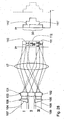
- Fig. 28 shows a variant of a raster module 101, which instead of two raster arrangements only a single raster arrangement 102 with raster elements 103 has.
- the construction of the raster arrangement 102 corresponds to that of the first raster arrangement 12 of the exemplary embodiments described above.
- the raster assembly 102 is in or adjacent to a pupil plane of the illumination system Fig. 28 arranged.
- the downstream components of the lighting system when performing Fig. 28 correspond to those of the embodiments discussed above. Shown in the Fig. 28 three channels I, II, III, in which the illumination light beam 3 is divided.
- the execution after Fig. 28 can have a much larger number of raster channels, as is also true for the embodiments described above.
- an angle variation section 104, 105 of an illumination angle variation device 106 is arranged in each case.
- the angle variation sections 104, 105 are designed as wedge plates which divert the illumination light bundles 107, 108 assigned to the channels I and III onto the illumination light bundle 109 assigned to the channel II. Due to the optical effect of the raster module 101 and of the condenser 17, this deflection by the angle variation sections 104, 105 causes the intensity contributions 110, 111 for channels I and III to be offset in the positive or negative y direction relative to an intensity contribution 112 of the channel II , The size of the offset depends on the imaging effect of the angle variation sections 104, 105 and their distance from the grid arrangement 102.
- Fig. 28 the sum of the intensity contributions 110 to 112 is shown on the right. This results in a staircase function.
- the number of stages depends on the number of grid elements 103 involved.
- a trapezoid function can also be achieved instead of the staircase function.
- the optically acting surfaces of the raster elements 28 with the respective shape variation 79, 88 can be designed in particular as free-form surfaces.
- the free-form surfaces are in particular designed so that they are not described by a rotationally symmetric function, ie by a spherical function or an aspherical function, but are rotationally symmetrical.
Landscapes
- Physics & Mathematics (AREA)
- General Physics & Mathematics (AREA)
- Exposure And Positioning Against Photoresist Photosensitive Materials (AREA)
- Microscoopes, Condenser (AREA)
Applications Claiming Priority (5)
| Application Number | Priority Date | Filing Date | Title |
|---|---|---|---|
| US77485006P | 2006-02-17 | 2006-02-17 | |
| US82329606P | 2006-08-23 | 2006-08-23 | |
| DE200610042452 DE102006042452A1 (de) | 2006-02-17 | 2006-09-09 | Beleuchtungssystem für die Mikro-Lithographie, Projektionsbelichtungsanlage mit einem derartigen Beleuchtungssystem, mikrolithographisches Herstellungsverfahren für Bauelemente sowie mit diesem Verfahren hergestelltes Bauelement |
| DE102006061711 | 2006-12-28 | ||
| PCT/EP2007/001362 WO2007093433A1 (de) | 2006-02-17 | 2007-02-16 | Beleuchtungssystem für die mikro-lithographie, projektionsbelichtungsanlage mit einem derartigen beleuchtungssystem |
Publications (2)
| Publication Number | Publication Date |
|---|---|
| EP1984789A1 EP1984789A1 (de) | 2008-10-29 |
| EP1984789B1 true EP1984789B1 (de) | 2013-11-06 |
Family
ID=39769580
Family Applications (1)
| Application Number | Title | Priority Date | Filing Date |
|---|---|---|---|
| EP07722838.5A Expired - Fee Related EP1984789B1 (de) | 2006-02-17 | 2007-02-16 | Beleuchtungssystem für die mikro-lithographie, projektionsbelichtungsanlage mit einem derartigen beleuchtungssystem |
Country Status (5)
| Country | Link |
|---|---|
| US (2) | US8705005B2 (ja) |
| EP (1) | EP1984789B1 (ja) |
| JP (1) | JP5068271B2 (ja) |
| KR (1) | KR101314974B1 (ja) |
| WO (1) | WO2007093433A1 (ja) |
Families Citing this family (24)
| Publication number | Priority date | Publication date | Assignee | Title |
|---|---|---|---|---|
| DE102005042005A1 (de) | 2004-12-23 | 2006-07-06 | Carl Zeiss Smt Ag | Hochaperturiges Objektiv mit obskurierter Pupille |
| TWI545352B (zh) | 2006-02-17 | 2016-08-11 | 卡爾蔡司Smt有限公司 | 用於微影投射曝光設備之照明系統 |
| KR101306503B1 (ko) | 2006-02-17 | 2013-09-09 | 칼 짜이스 에스엠티 게엠베하 | 마이크로리소그래피 투영 노광 장치의 조명 시스템용 광 인터그레이터 |
| JP5068271B2 (ja) | 2006-02-17 | 2012-11-07 | カール・ツァイス・エスエムティー・ゲーエムベーハー | マイクロリソグラフィ照明システム、及びこの種の照明システムを含む投影露光装置 |
| DE102007023411A1 (de) | 2006-12-28 | 2008-07-03 | Carl Zeiss Smt Ag | Optisches Element, Beleuchtungsoptik für die Mikrolithographie mit mindestens einem derartigen optischen Element sowie Beleuchtungssystem mit einer derartigen Beleuchtungsoptik |
| EP2073061A3 (de) | 2007-12-22 | 2011-02-23 | LIMO Patentverwaltung GmbH & Co. KG | Vorrichtung zur Ausleuchtung einer Fläche sowie Vorrichtung zur Beaufschlagung eines Arbeitsbereichs mit Licht |
| DE102009017941A1 (de) | 2008-06-19 | 2009-12-24 | Carl Zeiss Smt Ag | Beleuchtungssystem für die Mikro-Lithographie sowie Projektionsbelichtungsanlage mit einem derartigen Beleuchtungssystem |
| EP2146248B1 (en) | 2008-07-16 | 2012-08-29 | Carl Zeiss SMT GmbH | Illumination system of a microlithographic projection exposure apparatus |
| DE102009006685A1 (de) | 2009-01-29 | 2010-08-05 | Carl Zeiss Smt Ag | Beleuchtungssystem für die Mikro-Lithographie |
| WO2010108516A1 (en) * | 2009-03-27 | 2010-09-30 | Carl Zeiss Smt Ag | Illumination optical system for euv microlithography and euv attenuator for an illumination optical system of this kind, illumination system and projection exposure installation having an illumination optical system of this kind |
| DE102010030089A1 (de) | 2010-06-15 | 2011-12-15 | Carl Zeiss Smt Gmbh | Beleuchtungsoptik für die Mikro-Lithografie sowie Projektionsbelichtungsanlage mit einer derartigen Beleuchtungsoptik |
| JP5850267B2 (ja) | 2010-08-30 | 2016-02-03 | カール・ツァイス・エスエムティー・ゲーエムベーハー | マイクロリソグラフィ投影露光装置の照明系 |
| KR101813307B1 (ko) | 2011-01-29 | 2017-12-28 | 칼 짜이스 에스엠티 게엠베하 | 마이크로리소그래픽 투영 노광 장치의 조명 시스템 |
| US9760012B2 (en) * | 2011-08-04 | 2017-09-12 | Nikon Corporation | Illumination device |
| DE102011086949A1 (de) | 2011-11-23 | 2013-05-23 | Carl Zeiss Smt Gmbh | Beleuchtungs- und Verlagerungsvorrichtung für eine Projektionsbelichtungsanlage |
| DE102011086944B4 (de) | 2011-11-23 | 2015-07-23 | Carl Zeiss Smt Gmbh | Korrekturvorrichtung zur Beeinflussung einer Intensität eines Beleuchtungslicht-Bündels |
| DE102013213545A1 (de) | 2013-07-10 | 2015-01-15 | Carl Zeiss Smt Gmbh | Beleuchtungsoptik für die Projektionslithografie |
| DE102015201086A1 (de) | 2014-02-05 | 2015-08-06 | Carl Zeiss Smt Gmbh | Beleuchtungsoptik für die Projektionslithografie |
| DE102014203347B4 (de) | 2014-02-25 | 2017-09-14 | Carl Zeiss Smt Gmbh | Beleuchtungsoptik für die Mikro-Lithografie sowie Projektionsbelichtungsanlage mit einer derartigen Beleuchtungsoptik |
| DE102014203348A1 (de) | 2014-02-25 | 2015-08-27 | Carl Zeiss Smt Gmbh | Bündelverteilungsoptik, Beleuchtungsoptik mit einer derartigen Bündelverteilungsoptik, optisches System mit einer derartigen Beleuchtungsoptik sowie Projektionsbelichtungsanlage mit einem derartigen optischen System |
| WO2015185374A1 (de) * | 2014-06-06 | 2015-12-10 | Carl Zeiss Smt Gmbh | Optisches system einer mikrolithographischen projektionsbelichtungsanlage |
| DE102014219112A1 (de) * | 2014-09-23 | 2016-03-24 | Carl Zeiss Smt Gmbh | Beleuchtungsoptik für die Projektionslithographie sowie Hohlwellenleiter-Komponente hierfür |
| DE102016205590A1 (de) * | 2016-04-05 | 2017-10-05 | Osram Gmbh | Beleuchtungsvorrichtung zum Erzeugen einer rechteckigen Lichtverteilung in einer Beleuchtungsebene |
| EP3570109A1 (en) * | 2018-05-14 | 2019-11-20 | ASML Netherlands B.V. | Illumination source for an inspection apparatus, inspection apparatus and inspection method |
Family Cites Families (71)
| Publication number | Priority date | Publication date | Assignee | Title |
|---|---|---|---|---|
| DE3343868A1 (de) | 1983-12-03 | 1985-06-13 | Zeiss Carl Fa | Objektiv mit kegelschnittflaechen fuer die mikrozonenabbildung |
| JPS60232552A (ja) * | 1984-05-02 | 1985-11-19 | Canon Inc | 照明光学系 |
| US5003567A (en) | 1989-02-09 | 1991-03-26 | Hawryluk Andrew M | Soft x-ray reduction camera for submicron lithography |
| JP2691226B2 (ja) | 1989-07-10 | 1997-12-17 | 株式会社ニコン | 赤外線撮像光学装置 |
| US5212588A (en) | 1991-04-09 | 1993-05-18 | The United States Of America As Represented By The United States Department Of Energy | Reflective optical imaging system for extreme ultraviolet wavelengths |
| DE4124311A1 (de) | 1991-07-23 | 1993-01-28 | Zeiss Carl Fa | Anordnung zur kohaerenzreduktion und strahlformung eines laserstrahls |
| US5420417A (en) * | 1991-10-08 | 1995-05-30 | Nikon Corporation | Projection exposure apparatus with light distribution adjustment |
| JP3208863B2 (ja) * | 1992-09-04 | 2001-09-17 | 株式会社ニコン | 照明方法及び装置、露光方法、並びに半導体素子の製造方法 |
| US5461456A (en) * | 1992-11-24 | 1995-10-24 | General Signal Corporation | Spatial uniformity varier for microlithographic illuminator |
| US5581605A (en) | 1993-02-10 | 1996-12-03 | Nikon Corporation | Optical element, production method of optical element, optical system, and optical apparatus |
| JP3440458B2 (ja) | 1993-06-18 | 2003-08-25 | 株式会社ニコン | 照明装置、パターン投影方法及び半導体素子の製造方法 |
| DE4327656A1 (de) | 1993-08-17 | 1995-02-23 | Steinheil Optronik Gmbh | Infrarot-Objektiv |
| DE19520563A1 (de) | 1995-06-06 | 1996-12-12 | Zeiss Carl Fa | Beleuchtungseinrichtung für ein Projektions-Mikrolithographie-Gerät |
| US5815310A (en) | 1995-12-12 | 1998-09-29 | Svg Lithography Systems, Inc. | High numerical aperture ring field optical reduction system |
| JP3041328B2 (ja) | 1996-03-21 | 2000-05-15 | 株式会社那須板金工業 | 平板葺き屋根構造 |
| US5686728A (en) | 1996-05-01 | 1997-11-11 | Lucent Technologies Inc | Projection lithography system and method using all-reflective optical elements |
| JPH11110791A (ja) | 1997-09-30 | 1999-04-23 | Pioneer Electron Corp | 光情報記録媒体の再生ピックアップ装置 |
| AU1053199A (en) | 1997-11-14 | 1999-06-07 | Nikon Corporation | Exposure apparatus and method of manufacturing the same, and exposure method |
| US6240158B1 (en) | 1998-02-17 | 2001-05-29 | Nikon Corporation | X-ray projection exposure apparatus with a position detection optical system |
| JP4238390B2 (ja) | 1998-02-27 | 2009-03-18 | 株式会社ニコン | 照明装置、該照明装置を備えた露光装置および該露光装置を用いて半導体デバイスを製造する方法 |
| DE19812803B4 (de) | 1998-03-16 | 2004-09-09 | Gf Messtechnik Gmbh | Verfahren zur Herstellung eines Raumfilter-Arrays und Raumfilter-Array |
| JP4329266B2 (ja) * | 1998-03-24 | 2009-09-09 | 株式会社ニコン | 照明装置、露光方法及び装置、並びにデバイス製造方法 |
| DE10138313A1 (de) | 2001-01-23 | 2002-07-25 | Zeiss Carl | Kollektor für Beleuchtugnssysteme mit einer Wellenlänge < 193 nm |
| EP0955641B1 (de) * | 1998-05-05 | 2004-04-28 | Carl Zeiss | Beleuchtungssystem insbesondere für die EUV-Lithographie |
| DE10053587A1 (de) | 2000-10-27 | 2002-05-02 | Zeiss Carl | Beleuchtungssystem mit variabler Einstellung der Ausleuchtung |
| US6859328B2 (en) | 1998-05-05 | 2005-02-22 | Carl Zeiss Semiconductor | Illumination system particularly for microlithography |
| US6396067B1 (en) | 1998-05-06 | 2002-05-28 | Koninklijke Philips Electronics N.V. | Mirror projection system for a scanning lithographic projection apparatus, and lithographic apparatus comprising such a system |
| DE19923609A1 (de) | 1998-05-30 | 1999-12-02 | Zeiss Carl Fa | Ringfeld-4-Spiegelsysteme mit konvexem Primärspiegel für die EUV-Lithographie |
| EP1293832A1 (en) | 1998-06-08 | 2003-03-19 | Nikon Corporation | Projection exposure apparatus and method |
| US6069739A (en) | 1998-06-30 | 2000-05-30 | Intel Corporation | Method and lens arrangement to improve imaging performance of microlithography exposure tool |
| KR20010075605A (ko) | 1998-11-06 | 2001-08-09 | 오노 시게오 | 노광방법 및 노광장치 |
| DE10040898A1 (de) * | 2000-08-18 | 2002-02-28 | Zeiss Carl | Beleuchtungssystem für die Mikrolithographie |
| DE19856575A1 (de) * | 1998-12-08 | 2000-09-14 | Zeiss Carl Fa | Projektions-Mikrolithographiegerät |
| US6445442B2 (en) * | 1998-12-08 | 2002-09-03 | Carl-Zeiss-Stiftung | Projection-microlithographic device |
| US6195201B1 (en) | 1999-01-27 | 2001-02-27 | Svg Lithography Systems, Inc. | Reflective fly's eye condenser for EUV lithography |
| US6033079A (en) | 1999-03-15 | 2000-03-07 | Hudyma; Russell | High numerical aperture ring field projection system for extreme ultraviolet lithography |
| KR100756767B1 (ko) | 1999-03-15 | 2007-09-07 | 마츠시타 덴끼 산교 가부시키가이샤 | 집속소자, 광헤드, 광정보 기록재생장치 및 광정보기록재생방법 |
| JP2000286189A (ja) | 1999-03-31 | 2000-10-13 | Nikon Corp | 露光装置および露光方法ならびにデバイス製造方法 |
| JP4717974B2 (ja) | 1999-07-13 | 2011-07-06 | 株式会社ニコン | 反射屈折光学系及び該光学系を備える投影露光装置 |
| EP1093021A3 (en) | 1999-10-15 | 2004-06-30 | Nikon Corporation | Projection optical system as well as equipment and methods making use of said system |
| JP2001185480A (ja) | 1999-10-15 | 2001-07-06 | Nikon Corp | 投影光学系及び該光学系を備える投影露光装置 |
| US6621557B2 (en) | 2000-01-13 | 2003-09-16 | Nikon Corporation | Projection exposure apparatus and exposure methods |
| US6867913B2 (en) | 2000-02-14 | 2005-03-15 | Carl Zeiss Smt Ag | 6-mirror microlithography projection objective |
| JP2004509856A (ja) | 2000-08-02 | 2004-04-02 | ビーエーエスエフ アクチェンゲゼルシャフト | リポ酸およびジヒドロリポ酸の製造方法 |
| DE10052289A1 (de) | 2000-10-20 | 2002-04-25 | Zeiss Carl | 8-Spiegel-Mikrolithographie-Projektionsobjektiv |
| JP2002158157A (ja) * | 2000-11-17 | 2002-05-31 | Nikon Corp | 照明光学装置および露光装置並びにマイクロデバイスの製造方法 |
| US20020171047A1 (en) * | 2001-03-28 | 2002-11-21 | Chan Kin Foeng | Integrated laser diode array and applications |
| JP3746436B2 (ja) * | 2001-05-10 | 2006-02-15 | ミサワホーム株式会社 | 木質様成形品の製造方法および木質様成形品製造装置 |
| DE10130212A1 (de) | 2001-06-22 | 2003-01-02 | Zeiss Carl Jena Gmbh | Objektiv |
| DE10139177A1 (de) | 2001-08-16 | 2003-02-27 | Zeiss Carl | Objektiv mit Pupillenobskuration |
| JP4859311B2 (ja) * | 2001-09-17 | 2012-01-25 | 株式会社リコー | レーザ照明光学系、該光学系を用いた露光装置、レーザ加工機、及び投射装置 |
| DE10148167A1 (de) | 2001-09-28 | 2003-04-17 | Zeiss Carl Jena Gmbh | Beleuchtungsanordnung |
| JP2003114387A (ja) | 2001-10-04 | 2003-04-18 | Nikon Corp | 反射屈折光学系および該光学系を備える投影露光装置 |
| JP4324957B2 (ja) * | 2002-05-27 | 2009-09-02 | 株式会社ニコン | 照明光学装置、露光装置および露光方法 |
| JP3698133B2 (ja) | 2002-08-30 | 2005-09-21 | ヤマハ株式会社 | マイクロレンズアレイ |
| JP3938040B2 (ja) | 2002-12-27 | 2007-06-27 | キヤノン株式会社 | 反射型投影光学系、露光装置及びデバイス製造方法 |
| JP2004252358A (ja) | 2003-02-21 | 2004-09-09 | Canon Inc | 反射型投影光学系及び露光装置 |
| JP2005003943A (ja) | 2003-06-12 | 2005-01-06 | Fuji Xerox Co Ltd | 光学素子およびその製造方法 |
| WO2005015314A2 (en) | 2003-07-30 | 2005-02-17 | Carl Zeiss Smt Ag | An illumination system for microlithography |
| US7408616B2 (en) | 2003-09-26 | 2008-08-05 | Carl Zeiss Smt Ag | Microlithographic exposure method as well as a projection exposure system for carrying out the method |
| ATE511668T1 (de) | 2004-02-17 | 2011-06-15 | Zeiss Carl Smt Gmbh | Beleuchtungssystem für eine mikrolithographische projektionsbelichtungsvorrichtung |
| US20050237623A1 (en) * | 2004-02-26 | 2005-10-27 | Damian Fiolka | Optical unit for an illumination system of a microlithographic projection exposure apparatus |
| JP4864869B2 (ja) | 2004-02-26 | 2012-02-01 | カール・ツァイス・エスエムティー・ゲーエムベーハー | マイクロリソグラフィ投影露光装置のための照明系 |
| US20070285644A1 (en) | 2004-09-13 | 2007-12-13 | Carl Zeiss Smt Ag | Microlithographic Projection Exposure Apparatus |
| DE102005042005A1 (de) | 2004-12-23 | 2006-07-06 | Carl Zeiss Smt Ag | Hochaperturiges Objektiv mit obskurierter Pupille |
| WO2006084478A1 (de) | 2005-02-08 | 2006-08-17 | Hentze-Lissotschenko Patentverwaltungs Gmbh & Co. Kg | Vorrichtung zur homogenisierung von licht und verfahren zur herstellung der vorrichtung |
| JP5030944B2 (ja) | 2005-04-26 | 2012-09-19 | カール・ツァイス・エスエムティー・ゲーエムベーハー | マイクロリソグラフィ露光装置のための照明システム |
| US7470556B2 (en) * | 2005-06-28 | 2008-12-30 | Aptina Imaging Corporation | Process for creating tilted microlens |
| JP5068271B2 (ja) | 2006-02-17 | 2012-11-07 | カール・ツァイス・エスエムティー・ゲーエムベーハー | マイクロリソグラフィ照明システム、及びこの種の照明システムを含む投影露光装置 |
| DE102007023411A1 (de) | 2006-12-28 | 2008-07-03 | Carl Zeiss Smt Ag | Optisches Element, Beleuchtungsoptik für die Mikrolithographie mit mindestens einem derartigen optischen Element sowie Beleuchtungssystem mit einer derartigen Beleuchtungsoptik |
| JP5035747B2 (ja) | 2007-03-16 | 2012-09-26 | 株式会社ニコン | オプティカルインテグレータ、照明光学装置、露光装置、およびデバイス製造方法 |
-
2007
- 2007-02-16 JP JP2008554687A patent/JP5068271B2/ja not_active Expired - Fee Related
- 2007-02-16 WO PCT/EP2007/001362 patent/WO2007093433A1/de active Application Filing
- 2007-02-16 EP EP07722838.5A patent/EP1984789B1/de not_active Expired - Fee Related
- 2007-02-16 KR KR1020087022233A patent/KR101314974B1/ko active IP Right Grant
-
2008
- 2008-08-12 US US12/190,179 patent/US8705005B2/en not_active Expired - Fee Related
-
2014
- 2014-02-27 US US14/192,264 patent/US9341953B2/en not_active Expired - Fee Related
Also Published As
| Publication number | Publication date |
|---|---|
| US9341953B2 (en) | 2016-05-17 |
| US8705005B2 (en) | 2014-04-22 |
| KR101314974B1 (ko) | 2013-10-04 |
| US20140176930A1 (en) | 2014-06-26 |
| JP2009527113A (ja) | 2009-07-23 |
| KR20090003216A (ko) | 2009-01-09 |
| EP1984789A1 (de) | 2008-10-29 |
| US20090021715A1 (en) | 2009-01-22 |
| WO2007093433A1 (de) | 2007-08-23 |
| JP5068271B2 (ja) | 2012-11-07 |
Similar Documents
| Publication | Publication Date | Title |
|---|---|---|
| EP1984789B1 (de) | Beleuchtungssystem für die mikro-lithographie, projektionsbelichtungsanlage mit einem derartigen beleuchtungssystem | |
| EP1282011B1 (de) | Reflektives Projektionsobjektiv für EUV-Photolithographie | |
| DE102008013229B4 (de) | Beleuchtungsoptik für die Mikrolithographie | |
| EP2382510B1 (de) | Beleuchtungssystem für die mikro-lithographie | |
| EP1845417B1 (de) | Beleuchtungssystem mit Zoomobjetiv | |
| WO2011091900A2 (de) | Facettenspiegel zum einsatz in der mikrolithografie | |
| DE102008043162A1 (de) | Abbildende Optik sowie Projektionsbelichtungsanlage für die Mikrolithographie mit einer derartigen abbildenden Optik | |
| DE102008041593A1 (de) | Beleuchtungsoptik für die Mikrolithographie | |
| DE102012209132A1 (de) | Beleuchtungsoptik für die Projektionslithographie | |
| EP1180726B1 (de) | Beleuchtungssystem für die Mikrolithographie | |
| DE102008033341A1 (de) | Projektionsobjektiv | |
| DE102007023411A1 (de) | Optisches Element, Beleuchtungsoptik für die Mikrolithographie mit mindestens einem derartigen optischen Element sowie Beleuchtungssystem mit einer derartigen Beleuchtungsoptik | |
| DE102012207866A1 (de) | Baugruppe für eine Projektionsbelichtungsanlage für die EUV-Projektionslithografie | |
| WO2024052059A1 (de) | Faserstrang für einen sektorheizer, sektorheizer und projektionsvorrichtung | |
| DE102011076658A1 (de) | Beleuchtungsoptik für die EUV-Projektionslithographie | |
| WO2005036266A1 (de) | Masken, lithographievorrichtung und halbleiterbauelement | |
| DE102019212017A1 (de) | Optisches Beleuchtungssystem zur Führung von EUV-Strahlung | |
| DE102011006003A1 (de) | Beleuchtungsoptik zum Einsatz in einer Projektionsbelichtungsanlage für die Mikrolithografie | |
| WO2019149462A1 (de) | Beleuchtungsoptik für die projektionslithographie | |
| DE102015208514A1 (de) | Facettenspiegel für die EUV-Projektionslithografie sowie Beleuchtungsoptik mit einem derartigen Facettenspiegel | |
| DE102013218130A1 (de) | Beleuchtungsoptik für die EUV-Projektionslithografie | |
| EP2824512B1 (de) | Beleuchtungsoptik für die Projektionslithografie | |
| DE102012210073A1 (de) | Beleuchtungsoptik für die EUV- Projektionslithographie | |
| WO2009135556A1 (de) | Projektionsoptik für die mikrolithografie mit intensitäts-korrektureinrichtung | |
| DE102006042452A1 (de) | Beleuchtungssystem für die Mikro-Lithographie, Projektionsbelichtungsanlage mit einem derartigen Beleuchtungssystem, mikrolithographisches Herstellungsverfahren für Bauelemente sowie mit diesem Verfahren hergestelltes Bauelement |
Legal Events
| Date | Code | Title | Description |
|---|---|---|---|
| PUAI | Public reference made under article 153(3) epc to a published international application that has entered the european phase |
Free format text: ORIGINAL CODE: 0009012 |
|
| 17P | Request for examination filed |
Effective date: 20080823 |
|
| AK | Designated contracting states |
Kind code of ref document: A1 Designated state(s): DE FR NL |
|
| RIN1 | Information on inventor provided before grant (corrected) |
Inventor name: LAYH, MICHAEL Inventor name: SINGER, WOLFGANG Inventor name: GERHARD, MICHAEL Inventor name: THOME, BRUNO Inventor name: DEGUENTHER, MARKUS |
|
| 17Q | First examination report despatched |
Effective date: 20090109 |
|
| DAX | Request for extension of the european patent (deleted) | ||
| RBV | Designated contracting states (corrected) |
Designated state(s): DE FR NL |
|
| RAP1 | Party data changed (applicant data changed or rights of an application transferred) |
Owner name: CARL ZEISS SMT GMBH |
|
| GRAP | Despatch of communication of intention to grant a patent |
Free format text: ORIGINAL CODE: EPIDOSNIGR1 |
|
| INTG | Intention to grant announced |
Effective date: 20130603 |
|
| GRAS | Grant fee paid |
Free format text: ORIGINAL CODE: EPIDOSNIGR3 |
|
| GRAA | (expected) grant |
Free format text: ORIGINAL CODE: 0009210 |
|
| AK | Designated contracting states |
Kind code of ref document: B1 Designated state(s): DE FR NL |
|
| REG | Reference to a national code |
Ref country code: NL Ref legal event code: T3 |
|
| REG | Reference to a national code |
Ref country code: DE Ref legal event code: R096 Ref document number: 502007012466 Country of ref document: DE Effective date: 20140102 |
|
| REG | Reference to a national code |
Ref country code: DE Ref legal event code: R097 Ref document number: 502007012466 Country of ref document: DE |
|
| PLBE | No opposition filed within time limit |
Free format text: ORIGINAL CODE: 0009261 |
|
| STAA | Information on the status of an ep patent application or granted ep patent |
Free format text: STATUS: NO OPPOSITION FILED WITHIN TIME LIMIT |
|
| 26N | No opposition filed |
Effective date: 20140807 |
|
| REG | Reference to a national code |
Ref country code: DE Ref legal event code: R097 Ref document number: 502007012466 Country of ref document: DE Effective date: 20140807 |
|
| REG | Reference to a national code |
Ref country code: FR Ref legal event code: ST Effective date: 20141031 |
|
| PG25 | Lapsed in a contracting state [announced via postgrant information from national office to epo] |
Ref country code: FR Free format text: LAPSE BECAUSE OF NON-PAYMENT OF DUE FEES Effective date: 20140228 |
|
| PGFP | Annual fee paid to national office [announced via postgrant information from national office to epo] |
Ref country code: DE Payment date: 20170217 Year of fee payment: 11 |
|
| PGFP | Annual fee paid to national office [announced via postgrant information from national office to epo] |
Ref country code: NL Payment date: 20170216 Year of fee payment: 11 |
|
| REG | Reference to a national code |
Ref country code: DE Ref legal event code: R119 Ref document number: 502007012466 Country of ref document: DE |
|
| REG | Reference to a national code |
Ref country code: NL Ref legal event code: MM Effective date: 20180301 |
|
| PG25 | Lapsed in a contracting state [announced via postgrant information from national office to epo] |
Ref country code: NL Free format text: LAPSE BECAUSE OF NON-PAYMENT OF DUE FEES Effective date: 20180301 |
|
| PG25 | Lapsed in a contracting state [announced via postgrant information from national office to epo] |
Ref country code: DE Free format text: LAPSE BECAUSE OF NON-PAYMENT OF DUE FEES Effective date: 20180901 |