EP1984221B1 - Motor-pumpenaggregat - Google Patents
Motor-pumpenaggregat Download PDFInfo
- Publication number
- EP1984221B1 EP1984221B1 EP07726264A EP07726264A EP1984221B1 EP 1984221 B1 EP1984221 B1 EP 1984221B1 EP 07726264 A EP07726264 A EP 07726264A EP 07726264 A EP07726264 A EP 07726264A EP 1984221 B1 EP1984221 B1 EP 1984221B1
- Authority
- EP
- European Patent Office
- Prior art keywords
- motor
- assembly according
- pump assembly
- pump
- working
- Prior art date
- Legal status (The legal status is an assumption and is not a legal conclusion. Google has not performed a legal analysis and makes no representation as to the accuracy of the status listed.)
- Expired - Fee Related
Links
- XAGFODPZIPBFFR-UHFFFAOYSA-N aluminium Chemical compound [Al] XAGFODPZIPBFFR-UHFFFAOYSA-N 0.000 claims description 12
- 229910052782 aluminium Inorganic materials 0.000 claims description 12
- 230000006641 stabilisation Effects 0.000 claims description 2
- 238000011105 stabilization Methods 0.000 claims description 2
- 239000004411 aluminium Substances 0.000 claims 2
- 238000010521 absorption reaction Methods 0.000 claims 1
- 230000004913 activation Effects 0.000 claims 1
- 239000012528 membrane Substances 0.000 description 33
- 238000007789 sealing Methods 0.000 description 13
- 238000002485 combustion reaction Methods 0.000 description 11
- 238000009434 installation Methods 0.000 description 10
- 238000004519 manufacturing process Methods 0.000 description 8
- 239000011324 bead Substances 0.000 description 7
- 239000000463 material Substances 0.000 description 6
- 238000003466 welding Methods 0.000 description 6
- 230000008859 change Effects 0.000 description 4
- 238000013016 damping Methods 0.000 description 4
- 230000000712 assembly Effects 0.000 description 3
- 238000000429 assembly Methods 0.000 description 3
- 238000007664 blowing Methods 0.000 description 3
- 238000006243 chemical reaction Methods 0.000 description 3
- 230000017525 heat dissipation Effects 0.000 description 3
- 238000001746 injection moulding Methods 0.000 description 3
- 239000007788 liquid Substances 0.000 description 3
- 230000035515 penetration Effects 0.000 description 3
- 230000009467 reduction Effects 0.000 description 3
- 238000003860 storage Methods 0.000 description 3
- 239000000126 substance Substances 0.000 description 3
- 230000006978 adaptation Effects 0.000 description 2
- 230000008901 benefit Effects 0.000 description 2
- 238000005553 drilling Methods 0.000 description 2
- 239000007789 gas Substances 0.000 description 2
- 238000002347 injection Methods 0.000 description 2
- 239000007924 injection Substances 0.000 description 2
- 238000005304 joining Methods 0.000 description 2
- 238000000034 method Methods 0.000 description 2
- 230000000737 periodic effect Effects 0.000 description 2
- 238000003825 pressing Methods 0.000 description 2
- 230000008569 process Effects 0.000 description 2
- 230000004044 response Effects 0.000 description 2
- 230000007704 transition Effects 0.000 description 2
- 241000191291 Abies alba Species 0.000 description 1
- 230000009471 action Effects 0.000 description 1
- 230000007423 decrease Effects 0.000 description 1
- 230000000694 effects Effects 0.000 description 1
- 239000013013 elastic material Substances 0.000 description 1
- 239000013536 elastomeric material Substances 0.000 description 1
- 238000005516 engineering process Methods 0.000 description 1
- 239000007770 graphite material Substances 0.000 description 1
- 230000005484 gravity Effects 0.000 description 1
- 239000000314 lubricant Substances 0.000 description 1
- 230000008092 positive effect Effects 0.000 description 1
- 238000005086 pumping Methods 0.000 description 1
- 230000033764 rhythmic process Effects 0.000 description 1
Images


Classifications
-
- B—PERFORMING OPERATIONS; TRANSPORTING
- B60—VEHICLES IN GENERAL
- B60T—VEHICLE BRAKE CONTROL SYSTEMS OR PARTS THEREOF; BRAKE CONTROL SYSTEMS OR PARTS THEREOF, IN GENERAL; ARRANGEMENT OF BRAKING ELEMENTS ON VEHICLES IN GENERAL; PORTABLE DEVICES FOR PREVENTING UNWANTED MOVEMENT OF VEHICLES; VEHICLE MODIFICATIONS TO FACILITATE COOLING OF BRAKES
- B60T17/00—Component parts, details, or accessories of power brake systems not covered by groups B60T8/00, B60T13/00 or B60T15/00, or presenting other characteristic features
- B60T17/002—Air treatment devices
- B60T17/008—Silencer devices
-
- B—PERFORMING OPERATIONS; TRANSPORTING
- B60—VEHICLES IN GENERAL
- B60T—VEHICLE BRAKE CONTROL SYSTEMS OR PARTS THEREOF; BRAKE CONTROL SYSTEMS OR PARTS THEREOF, IN GENERAL; ARRANGEMENT OF BRAKING ELEMENTS ON VEHICLES IN GENERAL; PORTABLE DEVICES FOR PREVENTING UNWANTED MOVEMENT OF VEHICLES; VEHICLE MODIFICATIONS TO FACILITATE COOLING OF BRAKES
- B60T17/00—Component parts, details, or accessories of power brake systems not covered by groups B60T8/00, B60T13/00 or B60T15/00, or presenting other characteristic features
- B60T17/02—Arrangements of pumps or compressors, or control devices therefor
-
- B—PERFORMING OPERATIONS; TRANSPORTING
- B60—VEHICLES IN GENERAL
- B60T—VEHICLE BRAKE CONTROL SYSTEMS OR PARTS THEREOF; BRAKE CONTROL SYSTEMS OR PARTS THEREOF, IN GENERAL; ARRANGEMENT OF BRAKING ELEMENTS ON VEHICLES IN GENERAL; PORTABLE DEVICES FOR PREVENTING UNWANTED MOVEMENT OF VEHICLES; VEHICLE MODIFICATIONS TO FACILITATE COOLING OF BRAKES
- B60T13/00—Transmitting braking action from initiating means to ultimate brake actuator with power assistance or drive; Brake systems incorporating such transmitting means, e.g. air-pressure brake systems
- B60T13/10—Transmitting braking action from initiating means to ultimate brake actuator with power assistance or drive; Brake systems incorporating such transmitting means, e.g. air-pressure brake systems with fluid assistance, drive, or release
- B60T13/24—Transmitting braking action from initiating means to ultimate brake actuator with power assistance or drive; Brake systems incorporating such transmitting means, e.g. air-pressure brake systems with fluid assistance, drive, or release the fluid being gaseous
- B60T13/46—Vacuum systems
- B60T13/52—Vacuum systems indirect, i.e. vacuum booster units
-
- F—MECHANICAL ENGINEERING; LIGHTING; HEATING; WEAPONS; BLASTING
- F04—POSITIVE - DISPLACEMENT MACHINES FOR LIQUIDS; PUMPS FOR LIQUIDS OR ELASTIC FLUIDS
- F04B—POSITIVE-DISPLACEMENT MACHINES FOR LIQUIDS; PUMPS
- F04B39/00—Component parts, details, or accessories, of pumps or pumping systems specially adapted for elastic fluids, not otherwise provided for in, or of interest apart from, groups F04B25/00 - F04B37/00
- F04B39/0027—Pulsation and noise damping means
- F04B39/0055—Pulsation and noise damping means with a special shape of fluid passage, e.g. bends, throttles, diameter changes, pipes
- F04B39/0061—Pulsation and noise damping means with a special shape of fluid passage, e.g. bends, throttles, diameter changes, pipes using muffler volumes
-
- F—MECHANICAL ENGINEERING; LIGHTING; HEATING; WEAPONS; BLASTING
- F04—POSITIVE - DISPLACEMENT MACHINES FOR LIQUIDS; PUMPS FOR LIQUIDS OR ELASTIC FLUIDS
- F04B—POSITIVE-DISPLACEMENT MACHINES FOR LIQUIDS; PUMPS
- F04B45/00—Pumps or pumping installations having flexible working members and specially adapted for elastic fluids
- F04B45/04—Pumps or pumping installations having flexible working members and specially adapted for elastic fluids having plate-like flexible members, e.g. diaphragms
- F04B45/043—Pumps or pumping installations having flexible working members and specially adapted for elastic fluids having plate-like flexible members, e.g. diaphragms two or more plate-like pumping flexible members in parallel
-
- F—MECHANICAL ENGINEERING; LIGHTING; HEATING; WEAPONS; BLASTING
- F04—POSITIVE - DISPLACEMENT MACHINES FOR LIQUIDS; PUMPS FOR LIQUIDS OR ELASTIC FLUIDS
- F04B—POSITIVE-DISPLACEMENT MACHINES FOR LIQUIDS; PUMPS
- F04B45/00—Pumps or pumping installations having flexible working members and specially adapted for elastic fluids
- F04B45/04—Pumps or pumping installations having flexible working members and specially adapted for elastic fluids having plate-like flexible members, e.g. diaphragms
- F04B45/047—Pumps having electric drive
-
- B—PERFORMING OPERATIONS; TRANSPORTING
- B60—VEHICLES IN GENERAL
- B60Y—INDEXING SCHEME RELATING TO ASPECTS CROSS-CUTTING VEHICLE TECHNOLOGY
- B60Y2400/00—Special features of vehicle units
- B60Y2400/81—Braking systems
Definitions
- the invention relates to a motor-pump unit for providing pressure for a brake actuator of a motor vehicle brake system with a vacuum brake booster, comprising a pump and a pump driving electric motor, wherein the pump is provided as a double diaphragm pump with two opposite working membranes, each between a pump housing and a Working space cover is clamped and thereby limits a working space and which are movable by means of a, eccentric and connecting rods crank drive, wherein the working space is associated with an inlet channel with inlet valve and an outlet with outlet valve.
- vacuum pumps are used which suck in residual air from the vacuum chamber and eject it into the atmosphere.
- vane pumps or swing vane pumps are used in the automotive industry for this purpose. These have inherent friction and must be lubricated to achieve an acceptable life.
- Vacuum pumps with wings driven by the internal combustion engine of the motor vehicle are therefore connected to the oil circuit of the internal combustion engine. Nevertheless, a significant proportion of the output from the engine power must be used to drive such a pump. And this even if the vacuum is already fully formed in the chamber to be evacuated. Therefore, it is useful to operate the vacuum pump with electrical energy and only turn on when the absolute pressure in the vacuum chamber rises above a predetermined value.
- the vacuum pump is not or temporarily not driven by the internal combustion engine. Therefore, electrically powered vacuum pumps are used in these vehicles.
- Diaphragm pumps are well known. From the DE 35 29 978 A1 is a motor-pump unit comprising a double-diaphragm pump with a rotating eccentric known, which is driven by an electric motor.
- a diaphragm pump which is used in particular in vacuum cleaner devices.
- the membrane pump described therein has four membranes, which are arranged in a circle around a drive shaft and are moved by means of an eccentric.
- a membrane pump is described with four membranes, which are connected to a single plastic molded part. A part of the membrane lies outside the working chamber to form valve flaps provided with circular slots. Seats in the housing or in the lid form an inlet or an outlet valve.
- An outlet passage provided in the pump housing directs the air to an outlet port through which the air is inflated.
- Object of the present invention is to provide a motor-pump unit, which includes a dry-running pump and the high requirements in terms of acoustic comfort takes into account. Another object of the invention is to improve the motor-pump unit with respect to its pumping action.
- the outlet channels are arranged in the working space covers and pump housing such that displaced from the work spaces air is passed into a crank drive surrounding the interior of the pump housing, and that an air outlet unit is provided which a low-noise blowing out of the air made possible from the interior.
- the interior also called crankcase, serves as a sound-damping room, since the blown-out air is not passed directly into the atmosphere and no Ausblasgehoff may arise.
- the air outlet unit has means for soundproofing.
- an airborne sound can be reduced when the air exits the air outlet unit.
- the air outlet unit closes sealingly according to an advantageous embodiment of the invention, a breakthrough of a wall of the pump housing.
- the breakthrough can thus fulfill the function of a mounting window during assembly of the motor-pump unit, whereby the assembly can be considerably simplified.
- the air outlet unit comprises a filter housing, a filter, an air outlet cover, an air outlet closure cap and a valve body and is provided as a preassemblable subassembly.
- a backflow of the ejected air and the penetration of liquid or gaseous substances into the air outlet unit are preferably prevented by the fact that the Heilauslassdeckel, the Heilauslassver gleichkappe and the valve body form a check valve.
- the filter housing, the Heilauslassver gleichkappe and the valve body may form the check valve.
- a captive assembly is achieved according to an advantageous embodiment by the filter housing is riveted to the air outlet cover.
- the Heilauslassdeckel is fastened by means of screw elements on the wall, whereby a sealed attachment is made possible in a simple manner.
- the two inlet channels are connected to each other via channels formed in the pump housing and have a common connection.
- a second connection is not necessary, whereby the installation space of the motor pump unit can be optimized.
- connection preferably has means for attaching a hose.
- connection is designed as Ansaugrohrstutzen.
- a further advantageous embodiment of a motor-pump unit according to the invention provides that an adapter is provided, which is sealingly secured in the terminal and having an adapter outlet, the adapter outlet having means for fixing a hose.
- the adapter can be adapted to individual customer requirements, without a change of the pump housing is necessary.
- the adapter can preferably be positioned in the connection by means of a latching connection or can be arranged rotatably in the connection by means of pin-shaped elements, wherein the pin-shaped elements engage in an outer groove of the adapter.
- the pump housing In order to obtain a motor-pump unit for a wide variety of installation conditions, the pump housing according to an advantageous embodiment of the invention, two opposite ports, wherein a connection is closed.
- one of the connections can be tightly closed by means of a plug or one of the connections remains closed during manufacture and is opened only when required, for example by drilling.
- the pump housing may preferably be made of plastic or aluminum, whereby a low weight of the motor-pump unit is achieved by the pump housing made of plastic.
- an aluminum pump housing allows good heat dissipation from the engine, which can extend the life of the engine.
- the work space cover can be made of plastic or aluminum, whereby the production of the work space cover can be simplified.
- An assembly simplification is achieved according to an advantageous embodiment in that the inlet valve and the outlet valve of a working space are each provided as a preassembled valve unit.
- a further simplification of the assembly can be achieved by the preassemblable valve unit can be integrated in each case in the working space cover and forms with this a preassemblable working space cover unit.
- the upper lid is welded or screwed to the lower lid. This can be done simultaneously without centering the upper lid on the lower lid without further means.
- a simple production of the working space cover is achieved according to an advantageous embodiment of the invention in that the inlet channel formed in the upper lid and the outlet channel between the upper lid and lower lid is provided.
- Optimum utilization of the passage area of the intake valve is preferably achieved by dividing the intake passage in the region of the inlet valve into a plurality of individual passages arranged annularly around a central axis of the intake valve.
- the inlet valve and the outlet valve each arranged obliquely to the axes of symmetry of the pump, whereby a space-optimized design of the working space cover is possible.
- the valves are preferably provided as plate valves with valve disc.
- positioning pins are provided for positioning valve discs according to an advantageous embodiment of the invention in the lower lid.
- the inlet and the outlet valve associated working space cover openings are provided, wherein the working space cover openings are arranged in a circular ring around a central axis of the valves.
- the inlet and outlet channels are arranged in the pump housing such that the two working chamber covers are configured identically.
- the working space cover for both sides of the pump the same and a storage of two different working space lids is not required.
- Abstandseinstellsch are provided to adjust the distance of the working space cover of the working diaphragm, whereby manufacturing tolerances and mounting tolerances can be compensated.
- the Abstandseinstellstoff can be provided in a simple manner, if according to an advantageous embodiment, the distance adjusting means by an adjustable connection between the connecting rod and one with the working diaphragm associated plunger are formed.
- Another advantageous embodiment of the invention provides that Abstandseinstellstoff provided to adjust the distance of the working space cover of the pump housing. This also makes it possible to compensate for manufacturing tolerances and assembly tolerances. For example, the adjustment of the distance by means of a welded connection or it is done by means of a screw connection between the working space cover and the pump housing.
- a centering of the crank drive within the pump housing is advantageously achieved by a motor shaft of the electric motor is mounted in a first, arranged in the engine bearing and in a second bearing, the second bearing in part by a motor housing and partly by the Pump housing is received, and that a motor shaft end protrudes into the pump housing. This can be dispensed with an additional storage of the motor shaft in the pump housing.
- crank drive eccentric and connecting rods
- An additional eccentric shaft can be omitted
- crank drive eccentric and connecting rods
- eccentric shaft which is connected to the motor shaft by means of a threaded connection, wherein central axes of the motor shaft and the eccentric shaft are aligned.
- a further component reduction can be achieved in that the eccentric are integrally formed as a double eccentric.
- the pump housing and the working space cover have means for defined positioning of the working space cover on the pump housing for easier installation of the working space cover.
- control of the motor-pump unit takes place via an electronic control unit in response to a signal from a sensor which detects a pressure difference between the vacuum chamber and the working chamber or an absolute pressure in the vacuum chamber of the brake booster.
- the connecting rods can be made of plastic weight-optimized, if the connecting rods according to a preferred embodiment in the region of a connecting rod injected support rings for the stabilization of ball bearings.
- An advantageous alternative provides that the connecting rods in the region of the connecting rod eye have a slot, whereby the ball bearings can be resiliently enclosed. An injection of said support rings is not required.
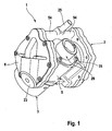
- Fig. 1 shows a first embodiment of a motor-pump unit 1 according to the invention in a spatial representation, which is provided for example for providing vacuum for a brake actuator of a motor vehicle brake system with a pneumatic brake booster, not shown.
- the motor-pump unit 1 comprises a pump 2 with a pump housing 5 and a pump 2 driving electric motor 3, which may be formed for example as a DC motor.
- the pump 2 is, as in particular Fig. 2 which shows shows the motor-pump unit 1 in longitudinal section through a first plane, provided as a double diaphragm pump with two opposite working membranes 4, which is clamped between the pump housing 5 and a working space cover 6 and thereby limits a working space 7.
- the working diaphragm 4 are movable in opposite directions by means of a crank drive 8, which per working diaphragm 4 comprises an eccentric 9 and a connecting rod 10.
- each working chamber 7 is associated with an inlet channel 11 with an inlet valve 12 and an outlet 13 with an outlet valve 14.
- the inlet valve 12 and the outlet valve 14 are formed as a check valve and each comprise a valve receptacle 15,16 and a valve disc 17,18, wherein the inlet and the outlet valve 12,14 are each provided as a preassemblable valve unit 20 which in a recess 19 the working space cover 6 can be mounted in order to thus again provide a pre-work space cover unit 21.
- the valve unit 20 and the working space cover unit 21 can be pre-assembled as an assembly, whereby the assembly of the motor-pump unit 1 is simplified.
- the valve receptacle 15 of the inlet valve 12 has a peg-shaped section, which protrudes into a corresponding recess in the working space cover 6 after assembly of the valve unit 20 in the working space cover 6. By this positioning, it is possible to facilitate the assembly of the valve unit 20.
- the valve seat 16 of the exhaust valve 14 also has a peg-shaped portion which after assembly in a corresponding recess of the Valve seat 15 of the inlet valve 12 protrudes.
- the valve unit 20 can be securely fastened, for example, by a threaded connection 22 in the working space cover 6. Further, the recess 19 is sealed by means of a valve cap 23 which is fixed by a screw member 24 to the working space cover unit 21.
- the two inlet channels 11 of the two working chambers 7 are connected by channels 5 extending in the pump housing 5 and open into a common port 25 in the pump housing 5, which in turn is connected via a vacuum hose, not shown, with a vacuum chamber of the brake booster, not shown, wherein the terminal 25, for example may be formed as Ansaugrohrstutzen which is fixed airtight in or on the pump housing 5.
- this intake manifold can be performed straight or angled and the airtight attachment in or on the pump housing 5 can be designed to be rotatable or fixed.
- an inlet channel 11 to the inlet valve 12 out into several smaller inlet channels 26 which are arranged in a circle about a central axis A of the valve unit 20 and open by means of a single channel 27 into the working space 7.
- the valve disc 17 of the intake valve 12 opens. If the working space 7 is reduced by the further rotation of the crank drive 8, the inlet valve 12 closes and the outlet valve 14 opens. The sucked-in residual air is blown out of the working space 7 via the channel 27 and the outlet channel 13.
- the outlet channel 13 is provided in the working space cover 6 and arranged in the pump housing 5, that the displaced from the working space 7 air is directed into an interior 28 of the pump housing 5.
- a provided in the pump housing 5 air outlet unit 29 allows a low-noise blowing out of the air from the interior 28.
- the air outlet unit 29 includes a check valve 49 comprising a one- or multi-part valve body 34, which prevents backflow of already expelled air and the penetration of liquid or gaseous substances into the crank chamber 28.
- the air outlet unit 29 has a filter 31 arranged in a filter housing 30, through which the air exits into the atmosphere.
- the air outlet unit 29 comprises an air outlet cover 32, an air outlet closure cap 33 and the valve body 34 and may be in the form of a preassembled subassembly be provided.
- the air outlet cover 32, the air outlet closure cap 33 and the filter housing 30 are each fastened with screw elements 35, 36, 37.
- further means can be provided, which are advantageously integrated in the subassembly air outlet unit 29.
- the check valve 49 opens by the valve body 34 at least partially lifts from through holes 38 in the air outlet cover 32 and the air through openings, not shown in the BeerauslassverBankkappe 33 and can escape through the filter 31 from the pump housing 5 into the atmosphere.
- the pressure in the interior 28 of the pump 2 to increase only by the small, necessary to open the check valve 49 differential pressure above atmospheric pressure and on the other hand, the pressure in the interior 28 is subject to periodic fluctuations in the cycle associated with the crank movement interior volume change. This results in a time average internal pressure below the atmospheric pressure.
- a motor shaft 39 of the electric motor 3 is mounted in a first, not shown, arranged in the engine 3 bearings and in a second bearing 40, wherein the second bearing 40 in part by a motor housing 41 and partly of the Pump housing 5 is received, wherein a motor shaft end 42 projects into the pump housing 5.
- An eccentric shaft 43 rigidly connected to the motor shaft 39 carries the crank drive 8 with the eccentrics 9 and the connecting rods 10, center axes M, E of the motor shaft 39 and the eccentric shaft 43 being in alignment.
- the eccentric 9 may be integrally formed as a double eccentric, which is arranged for example by pressing on the eccentric shaft 43.
- double eccentric is made by pressing the eccentric shaft 43 in two disk-shaped, rotated by 180 ° to each other single eccentric 9. Die Exzenterwelle 9 ist in der Fig. 2 strictly.
- the eccentric shaft 43 For simplified assembly of the motor-pump unit 1, it is advantageous to join the eccentric shaft 43 and the motor shaft 39 within the pump housing 5.
- the eccentric shaft 43 at its motor end a Have threaded connection in the form of an internal or external thread.
- at least one tool engagement surface is provided on the motor side or on the free shaft end. A polygonal configuration of the free end is just as conceivable.
- the working diaphragm 4 separates the working space 7 from the crank space 28 and is fixedly connected to a plunger 45, wherein the preferably non-deformable plunger 45 can be encapsulated by the elastically deformable material of the working diaphragm 4.
- the plunger 45 is fixedly connected to the connecting rod 10 in this embodiment by means of a threaded connection.
- the plunger 45 may be provided in one piece with the connecting rod 10 according to another embodiment. If the plunger 45 and the connecting rod 10 are provided as separate components, then these are depending on the material of the components wears or screwed together.
- the connecting rods 10 are movably mounted on the eccentrics 9 by means of ball bearings 46.
- the working space cover 6 has a three-dimensional shape, which is adapted to the envelope of a working-side membrane surface 52, which is caused by the tilting movement of the ram 45 moved by the crank drive 8 is induced.
- the adaptation of the three-dimensional working space lid inner contour to the envelope is achieved by maintaining a predetermined small distance between the areas of the heavy deformable portion 50 of the working diaphragm 4 and the working space cover 6, while the distance in the areas of the easily deformable portion 44 of the working diaphragm 4 and the membrane bead 51 to the working space cover 6 is selected to zero.
- the distance adjusting means are formed by an adjustable connection between the connecting rod 10 and plunger 45.
- An example of such a connection is a welded joint.
- Another example is a screw connection with inserted washers.
- Another embodiment provides the Abstandseinstellstoff as an adjustable connection between the pump housing 5 and the working space cover 6.
- An example of such an adjustable connection is a welded joint
- another example is a screw connection of the pump housing 5 and the working space cover 6, in which the tightening torque of the Connecting screws the clamping deformation of the membrane rim 51 designed for this purpose membrane rim is determined.
- a weight-optimized unit 1 is obtained in that the pump housing 5 and the working space cover 6 are made of plastic, for example by means of injection molding, wherein the components are preferably joined together by ultrasonic welding. Furthermore, the pump housing 5 and the working space cover 6 or, only the pump housing 5 may be made of aluminum, since aluminum allows good heat dissipation from the motor 3. Thus, a material combination of plastic and aluminum for the two components pump housing 5 and 6 working space cover conceivable.
- the inlet and outlet channels 11,13 are positioned in the pump housing 5 such that the two working space cover 6 can be configured identically.
- the working space cover 6 and the pump housing 5 means for the defined positioning of the working space cover 6 on the pump housing 5 in order to facilitate the assembly and to preclude erroneous positioning.
- an asymmetrical joining contour, as well as projections in the connecting surface can be provided.
- an asymmetrical hole pattern is suitable as the positioning means.
- Flow channels which penetrate the connecting surface between the working space cover 6 and the pump housing 5, are gas-tight in the transitions between the working space cover 6 and the pump housing 5 to their environment - for example, the use of sealing elements 47 by means of a gas-tight welding.
- the above-described air outlet unit 29, consisting essentially of filter housing 30, filter 31, valve cover 32, valve closure cap 33 and valve body 34 is formed as a preassembled unit and provided for installation in an opening 48 of a motor 3 facing away from the wall 53 of the pump housing 5.
- the abutment of the disc-shaped valve body 34, for example, on the valve cover 32 is achieved by means of the valve closure cap 33.
- the opening 48 before the onset of the air outlet unit 29 fulfills the function of a mounting window, which allows access to the interior 28 of the pump housing 5.
- the outlet channels 13 open into the interior 28 of the pump housing 5, so that this serves as an acoustic damping chamber to reduce the exit sound when ejecting air from the working spaces 7.
- the 4 to 6 show a second embodiment of a motor-pump assembly 101.
- the structure and function are largely consistent with the first embodiment, so that the same components or components with the same function have the same, increased by 100 reference numerals.
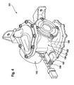
- Fig. 4 shows the second embodiment of the motor-pump assembly 101 according to the invention in a spatial representation, which comprises a pump 102 with a pump housing 105 and the pump 102 driving electric motor 103, wherein the motor 103 may be formed, for example, as a DC motor.
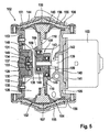
- the pump 102 is, as in particular Fig. 5 It can be seen, which shows the motor-pump unit 101 in longitudinal section through a first plane, provided as a double diaphragm pump with two opposite working membranes 104, which is clamped between the pump housing 105 and a working space cover 106 and thereby limits a working space 107.
- the working membrane 104 are by means of a crank drive 108 in opposite directions, which per working membrane 104 comprises an eccentric 109 and a connecting rod 110.
- Fig. 6 the working space cover 106 of the motor-pump unit 101 is shown cut. It can be seen that the working space cover 106 has an upper cover 155 and a lower cover 156 which, depending on the material - plastic or aluminum - airtight welded or screwed together.
- the centering of the upper lid 155 on the lower lid 156 is effected for example by a molded on the upper lid 155 welding allowance 165, which engages in the assembly of the upper lid 155 in a corresponding contour 166.
- a sealingly mounted therein adapter 157 via which the connected brake booster is evacuated.
- the adapter 157 may be angled as shown. Likewise, however, according to customer requirements, a straight adapter 157 is possible.
- an adapter outlet 158 to which a vacuum hose, not shown, is fastened, designed differently depending on the connection.
- a snap or snap closure conceivable.
- the adapter 157 can either be positioned in the port 125 by means of a latching connection, or the port adapter connection is rotatably provided.
- the rotatable configuration of the connection can be realized, for example, by means of pin-shaped elements 159, which project into bores of the connection 125 and engage in a non-visible external groove of the adapter 157.
- the port 125 opens into a housing bore, not shown, which branches into two channels formed in the pump housing 105, which lead to the two working space lids 106. This makes it possible to design the working space cover 106 for both sides of the pump 102 the same, whereby the assembly is considerably simplified.
- a second port 125 may be provided on the opposite side of the pump housing 105. This makes it possible, depending on the customer and installation conditions of the motor-pump unit 101 to connect the adapter 157 either on the one or the opposite side.
- one of the connections 125 can be tightly closed by means of a plug. It is also conceivable to leave one of the connections 125 closed during manufacture and to open it only when required, for example by drilling.
- inlet channel 111 is provided, which is airtightly connected to said pump housing channel by means of a sealing element and the sucked air to an inlet valve 112 passes.
- the inlet valve 112 is preferably designed as a plate valve with a valve disk 117 made of elastic material.
- the total passage area to be covered by the elastomeric valve disc 117 is expediently divided into a plurality of small passage areas, each with a circular cross-section.
- the inlet channel 111 in the upper lid 155 branches into a corresponding number of individual channels 160, which are arranged annularly around a central axis of the inlet valve 111.
- the outlet valve 114 which is also designed as a plate valve with a valve disc 118 made of elastomeric material.
- an exhaust passage 113 is formed between upper cover 155 and lower cover 156.
- the working space cover 106 also in this exemplary embodiment has a three-dimensional shape which is adapted to the envelope of a working-surface-side membrane surface 152 which is induced by the tilting movement of a plunger 145 moved by the crank drive 108.
- the adaptation of the three-dimensional workspace lid inner contour to the envelope is accomplished by maintaining a predetermined small distance between the areas of a hard deformable portion 150 of the working diaphragm 104 and the workspace lid 106 while spacing in the regions of easily deformable portion 144 of the working diaphragm 104 and a diaphragm bead 151 is selected to zero.
- the small distance of the working space lid inner contour of the envelope of the working space side membrane surface 152 in the central region of the membrane 104 prevents its abutment on the working space cover 106 during operation of the pump 102 and allows at the top dead center of the crank drive 108, an air flow between the working space 107 and the work space ceiling openings 161,162.
- the working space cover openings 161, 166 belong to the so-called damaged volume, that is to say the residual volume remaining during the ejection.
- the remaining air under atmospheric pressure expands during the suction process, whereby less volume can be sucked. It makes sense, therefore Work space cover openings 161,162 with minimal volume to design.
- Inlet and outlet valves 112, 114 are therefore tangential to the working space lid inner contour, i. arranged obliquely to the planes of symmetry of the pump 102, and the working space cover openings 161,162 are formed as short holes.
- This embodiment of the work space cover 106 takes as a further advantage a small space to complete.
- the ejected air is passed via the outlet channel 113 in the working space cover 106 to an outlet channel, not shown, in the pump housing 105.
- the outlet channels 113 in the working space cover 106 and pump housing 105 are connected airtight by means of a sealing element.
- the two outlet channels in the pump housing 105 open into an interior 128 of the pump housing 105, the so-called crank chamber.
- the lower cover 156 in the region of the valves 112,114 each have a positioning pin 163,164 which serves to guide the valve disks 117,118.
- the inlet valve 112 further comprises two provided on the upper lid 155 coaxial circular sealing surfaces 167,168, which are configured as circumferential projections, wherein a sealing surface 167 outside of the individual channels 160 and a sealing surface 168 is disposed within the individual channels 160.
- a provided in the pump housing 105 air outlet unit 129 allows a low-noise blowing out of the air from the interior 128.
- the interior 128, also called the crankcase, serves as a Schalldämpfungsraum.
- the air outlet unit 129 includes, as already described for the first embodiment, a check valve 149 comprising a one- or multi-part valve body 134, which prevents backflow of already ejected air and the penetration of liquid or gaseous substances into the crank chamber 128.
- the air outlet unit 129 has a filter 131 arranged in a filter housing 130, through which the air exits into the atmosphere.
- the air outlet unit 129 includes an air outlet cover 132, an air outlet closure cap 133, and the valve body 134, and may be provided as a pre-assembled assembly.
- the air outlet cap 132, the air outlet cap 133, and the filter housing 130 are fastened with screw members 135, 137, respectively.
- the filter housing 130 is riveted to the Lucasauslassdeckel 132.
- further means can be provided, which are advantageously integrated into the subassembly air outlet unit 129.
- the check valve 149 opens by at least partially lifting off the valve body 134 from through holes 138 in the air outlet cover 132 and the air through openings, not shown, in the air outlet cap 133 and escape through the filter 131 from the pump housing 105 into the atmosphere.
- the pressure in the interior 128 of the pump 102 increase only by the small, to open the check valve 149 necessary differential pressure value above the atmospheric pressure and on the other hand, the pressure in the interior 128 is subjected to periodic fluctuations in the rhythm of the associated with the crank movement interior volume change. This results in a time average internal pressure below the atmospheric pressure.
- the attachment of the motor 103 to the pump housing 105 by means not shown screw elements which engage in introduced into the pump housing 105 threaded inserts when the pump housing 105 is formed of plastic.
- the motor shaft 139 serves in this embodiment simultaneously as the eccentric shaft 143, which carries the crank drive 108 with the eccentrics 109 and the connecting rods 110.
- the eccentric shaft 143 which carries the crank drive 108 with the eccentrics 109 and the connecting rods 110.
- a separate embodiment of motor shaft 139 and eccentric shaft 143 described according to the first embodiment is possible.
- the eccentric 109 may for example also be offset by 90 ° to each other, the offset causes a lower torque by 90 ° and thus has a positive effect on the noise and the startup of the pump 102.
- the working membrane 104 separates the working space 107 from the crank space 128 and is firmly connected to the plunger 145, wherein the preferably non-deformable plunger 145 can be encapsulated by the elastically deformable material of the membrane 104.
- the plunger 145 may be fixedly connected to the connecting rod 110 either by means of a weld or a threaded connection. However, it may also be integrally provided with the connecting rod 110.
- the connecting rods 110 are movably mounted on the eccentrics 109 by means of ball bearings 146.
- connecting rods 110 are made of plastic, injected support rings 169 in the region of a connecting rod eye 171 can stabilize the seating of the ball bearings 146 in the connecting rods 110.
- the Ball bearing 146 resiliently enclose, as out Fig. 7 which shows a further embodiment of a connecting rod 110.
- means are provided to adjust the distance of the working space cover 106 of the working diaphragm 104, whereby manufacturing tolerances or assembly tolerances are compensated. It is intended to carry out the adjustment during the final assembly of the motor-pump unit 101.
- the distance adjusting means are formed by an adjustable connection between the connecting rod 110 and plunger 145.
- An example of such a connection is a welded joint.
- Another example is a screw connection with inserted washers.
- Another embodiment also provides in this embodiment, the Abstandseinstellstoff as an adjustable connection between the pump housing 105 and the working space cover 106 before.
- An example of such an adjustable connection is a welded connection
- another example is a screw connection of the pump housing 105 and the working space cover 106, in which the tightening torque of the connecting screws determines the clamping deformation of the membrane edge 151 designed as a membrane bead 151 for this purpose.
- a weight-optimized unit 101 is obtained by the fact that the pump housing 105 and the working space cover 106 are made of plastic, for example by means of injection molding, wherein individual parts produced by injection molding are preferably joined together by ultrasonic welding. Furthermore, the pump housing 105 and the Working space cover 106 or only the pump housing 105 may be made of aluminum, since aluminum allows good heat dissipation from the motor 103. So a material combination of plastic and aluminum for the two parts is conceivable.
- the inlet and outlet channels 111,113 are positioned in the pump housing 105 such that the two working space cover 106 can be configured identically.
- the working space cover 106 and the pump housing 105 means for the defined positioning of the working space cover 106 on the pump housing 105 in order to facilitate the assembly and to preclude erroneous positioning.
- an asymmetrical joining contour, as well as projections in the connecting surface can be provided.
- an asymmetrical hole pattern is used as positioning means.
- Flow channels which penetrate the connection surface between the working space cover 106 and the pump housing 105 are gas-tight in the transitions between the working space cover 106 and the pump housing 105 to their environment - for example by the use of sealing elements 147 by means of a gas-tight welding.
- the air outlet unit 129 described above consisting essentially of filter housing 130, filter 131, valve cover 132, valve closure cap 133 and valve body 134 is formed as a preassembled unit and provided for installation in an opening 148 of the motor 103 facing away from wall 153 of the pump housing 105.
- the Installation of the example disc-shaped valve body 134 on the valve cover 132 by means of the valve cap 133 reached.
- the opening 148 before the onset of the air outlet unit 129 fulfills the function of a mounting window which allows access to the interior 128 of the pump housing 105.
- the outlet channels 113 open into the interior 128 of the pump housing 105, so that this serves as an acoustic damping chamber to reduce the exit sound when ejecting air from the working spaces 107.
- the control of the motor-pump assemblies described in the embodiments 1,101 carried by an electronic control unit (ECU), not shown, in response to a signal from a sensor which detects a pressure difference between the vacuum chamber and a working chamber or the absolute pressure in the vacuum chamber of the brake booster.
- the motor-pump unit 101 is turned on when the signal falls below a first predetermined lower value and turned off when the signal exceeds a second certain upper value.
- the control unit can be integrated in an electronic control unit ECU, for example that of the brake system, or provided as a separate control unit.
- motor-pump units 1,101 are not limited to the described application of the provision of vacuum.
- Such units 1,101 can be used anywhere where gases are to be brought with high efficiency and low noise emissions from a first pressure level to a higher second pressure level.
- an application of the unit 1,101 according to the invention as a compressor is conceivable, in which Application preferably the direction of installation of the valves is reversed, so that the suction of the air from the interior 28,128 of the pump housing 5,105 and the discharge of compressed air via the port 25,125 takes place.
Landscapes
- Engineering & Computer Science (AREA)
- Mechanical Engineering (AREA)
- General Engineering & Computer Science (AREA)
- Transportation (AREA)
- Reciprocating Pumps (AREA)
- Valves And Accessory Devices For Braking Systems (AREA)
- Compressor (AREA)
Applications Claiming Priority (3)
| Application Number | Priority Date | Filing Date | Title |
|---|---|---|---|
| DE102006006493 | 2006-02-10 | ||
| DE102007005223A DE102007005223A1 (de) | 2006-02-10 | 2007-01-29 | Motor-Pumpenaggregat |
| PCT/EP2007/050913 WO2007090764A1 (de) | 2006-02-10 | 2007-01-30 | Motor-pumpenaggregat |
Publications (2)
| Publication Number | Publication Date |
|---|---|
| EP1984221A1 EP1984221A1 (de) | 2008-10-29 |
| EP1984221B1 true EP1984221B1 (de) | 2009-12-09 |
Family
ID=38336207
Family Applications (1)
| Application Number | Title | Priority Date | Filing Date |
|---|---|---|---|
| EP07726264A Expired - Fee Related EP1984221B1 (de) | 2006-02-10 | 2007-01-30 | Motor-pumpenaggregat |
Country Status (8)
| Country | Link |
|---|---|
| US (1) | US8702180B2 (zh) |
| EP (1) | EP1984221B1 (zh) |
| JP (1) | JP4971363B2 (zh) |
| KR (1) | KR101303489B1 (zh) |
| CN (1) | CN101384459B (zh) |
| BR (1) | BRPI0707632A2 (zh) |
| DE (2) | DE102007005223A1 (zh) |
| WO (1) | WO2007090764A1 (zh) |
Families Citing this family (39)
| Publication number | Priority date | Publication date | Assignee | Title |
|---|---|---|---|---|
| AU6867801A (en) * | 2000-06-20 | 2002-01-02 | Corixa Corp | Fusion proteins of mycobacterium tuberculosis |
| DE102007005223A1 (de) * | 2006-02-10 | 2007-09-13 | Continental Teves Ag & Co. Ohg | Motor-Pumpenaggregat |
| DE102008005820A1 (de) * | 2007-09-11 | 2009-03-12 | Continental Teves Ag & Co. Ohg | Motor-Pumpenaggregat |
| EP2865449B1 (en) | 2008-10-22 | 2019-04-03 | Graco Minnesota Inc. | Portable airless sprayer |
| DE102009054499A1 (de) | 2008-12-19 | 2010-07-01 | Continental Teves Ag & Co. Ohg | Motor-Pumpenaggregat |
| DE102009054941A1 (de) * | 2009-12-18 | 2011-06-22 | Continental Teves AG & Co. OHG, 60488 | Motor-Pumpenaggregat |
| WO2011127314A2 (en) | 2010-04-07 | 2011-10-13 | Chart Sequal Technologies Inc. | Portable oxygen delivery device |
| KR20130102069A (ko) | 2010-09-15 | 2013-09-16 | 콘티넨탈 테베스 아게 운트 코. 오하게 | 자동차 브레이크 시스템용 브레이크 구동 유닛 및 자동차 브레이크 시스템의 브레이크 구동 유닛을 위한 진공을 제공하는 모터 펌프 유닛 |
| DE102010062160A1 (de) * | 2010-11-30 | 2012-05-31 | Continental Teves Ag & Co. Ohg | Motor-Pumpenaggregat |
| DE102011089590A1 (de) | 2011-01-31 | 2012-08-02 | Continental Automotive Gmbh | Verfahren zur Funktionsüberwachung einer Sicherheitsüberwachung einer Steuereinheit |
| KR101346117B1 (ko) * | 2011-04-20 | 2013-12-31 | 성백철 | 소음저감 구조를 가지는 자동차 브레이크 시스템용 진공펌프 |
| BR112014018915B1 (pt) | 2012-02-01 | 2021-11-03 | Continental Teves Ag & Co. Ohg | Unidade de bomba que pode ser acionada por motor elétrico |
| CN103670998A (zh) * | 2012-09-20 | 2014-03-26 | 艾伦·桑德 | 一种电机泵组件 |
| KR101449300B1 (ko) * | 2013-06-14 | 2014-10-08 | 양승빈 | 다이어프램 펌프 |
| KR101432134B1 (ko) * | 2013-06-20 | 2014-08-20 | 주식회사 영진 엔테크 | 정량펌프 및 그 제어방법 |
| DE102013015960A1 (de) | 2013-09-25 | 2014-04-10 | Daimler Ag | Leistungsmodul sowie Verfahren zur Herstellung eines Leistungsmoduls |
| DE102013220594A1 (de) * | 2013-10-11 | 2015-04-16 | Continental Teves Ag & Co. Ohg | Ausblaseinheit für eine Vakuumpumpe |
| DE102013222245A1 (de) * | 2013-10-31 | 2015-04-30 | Continental Teves Ag & Co. Ohg | Vakuumpumpe mit einem Deckel |
| WO2015119717A1 (en) | 2014-02-07 | 2015-08-13 | Graco Minnesota Inc. | Pulseless positive displacement pump and method of pulselessly displacing fluid |
| JP6349135B2 (ja) * | 2014-04-11 | 2018-06-27 | 東京理化器械株式会社 | ダイヤフラム真空ポンプ |
| DE102014214302A1 (de) * | 2014-07-22 | 2016-01-28 | Continental Teves Ag & Co. Ohg | Ausblaseinheit und Pumpenaggregat mit Ausblaseinheit |
| DE102014215867A1 (de) * | 2014-08-11 | 2016-02-11 | Continental Teves Ag & Co. Ohg | Motor-Pumpenaggregat |
| DE102014216721A1 (de) * | 2014-08-22 | 2016-02-25 | Continental Teves Ag & Co. Ohg | Elektromotor-Pumpenaggregat |
| EP3289220B1 (en) * | 2015-04-27 | 2021-08-04 | Ideal Industries, Inc. | Personal air sampling pump assembly |
| DE102015111516A1 (de) * | 2015-07-16 | 2017-01-19 | Knorr-Bremse Systeme für Nutzfahrzeuge GmbH | Verfahren und Vorrichtung zur Steuerung einer geräuscharmen Druckluftaufbereitung |
| US11007545B2 (en) | 2017-01-15 | 2021-05-18 | Graco Minnesota Inc. | Handheld airless paint sprayer repair |
| JP6876323B2 (ja) * | 2017-02-03 | 2021-05-26 | 応研精工株式会社 | モーター付きポンプ |
| US11022106B2 (en) | 2018-01-09 | 2021-06-01 | Graco Minnesota Inc. | High-pressure positive displacement plunger pump |
| US11986850B2 (en) | 2018-04-10 | 2024-05-21 | Graco Minnesota Inc. | Handheld airless sprayer for paints and other coatings |
| WO2020243438A1 (en) | 2019-05-31 | 2020-12-03 | Graco Minnesota Inc. | Handheld fluid sprayer |
| CN113906215B (zh) * | 2019-06-03 | 2024-03-29 | 固瑞克明尼苏达有限公司 | 用于电动泵的隔膜泵驱动器 |
| CN112519738B (zh) * | 2019-09-18 | 2022-04-26 | 广州汽车集团股份有限公司 | 真空助力制动系统、制动控制方法和制动控制设备 |
| DE102019214307A1 (de) * | 2019-09-19 | 2021-03-25 | Continental Teves Ag & Co. Ohg | Elektromotorisch angetriebenes Aggregat für ein Fahrzeug |
| CN112814877A (zh) * | 2019-11-18 | 2021-05-18 | 广东美的生活电器制造有限公司 | 隔膜泵和饮品酿造机 |
| EP4073381A4 (en) * | 2019-12-11 | 2024-01-17 | Leggett & Platt Canada Co | PUMP ARRANGEMENT |
| AU2021246059A1 (en) | 2020-03-31 | 2022-10-06 | Graco Minnesota Inc. | Electrically operated displacement pump |
| US10968903B1 (en) | 2020-06-04 | 2021-04-06 | Graco Minnesota Inc. | Handheld sanitary fluid sprayer having resilient polymer pump cylinder |
| US10926275B1 (en) | 2020-06-25 | 2021-02-23 | Graco Minnesota Inc. | Electrostatic handheld sprayer |
| CN116420020A (zh) * | 2020-11-09 | 2023-07-11 | 辟缔熙机械股份有限公司 | 用于隔膜压缩机的主动喷油系统 |
Family Cites Families (19)
| Publication number | Priority date | Publication date | Assignee | Title |
|---|---|---|---|---|
| DE275455C (zh) * | ||||
| DE2212322A1 (de) | 1972-03-15 | 1973-09-20 | Erich Becker | Membranpumpe zur druck- oder vakuumerzeugung |
| GB1354037A (en) | 1971-06-01 | 1974-06-05 | Becker E | Diaphragm pumps |
| US3947156A (en) | 1972-03-08 | 1976-03-30 | Erich Becker | Diaphragm pump, particularly for the generation of vacuum |
| JPS59172238U (ja) * | 1983-05-04 | 1984-11-17 | 日産自動車株式会社 | ダイヤフラム式バキユ−ムポンプ |
| JPS6069375U (ja) * | 1983-10-18 | 1985-05-16 | 真空機工株式会社 | ダイヤフラム式真空ポンプの消音装置 |
| JPS60167175U (ja) | 1984-04-16 | 1985-11-06 | 三菱電機株式会社 | ダイアフラム型ポンプ装置 |
| JPS61106988A (ja) * | 1984-10-02 | 1986-05-24 | Anretsuto:Kk | プランジヤ型のフリ−ピストン式ダイヤフラムポンプ |
| DE3529978A1 (de) * | 1985-08-22 | 1987-03-05 | Ashauer Ernst | Membranpumpe |
| CN86208201U (zh) * | 1986-10-29 | 1987-12-12 | 广州医疗器械厂 | 单相双膜片低噪音无油气泵 |
| JPH0629503Y2 (ja) * | 1987-07-13 | 1994-08-10 | 株式会社ワイ・テイ・エス | ダイアフラムポンプ |
| CN2061981U (zh) * | 1990-02-21 | 1990-09-12 | 凌琳 | 膜片式泵 |
| US5380267A (en) * | 1993-06-18 | 1995-01-10 | Datascope Investment Corp. | Noise-attenuating pneumatic compressor and medical apparatus incorporating same |
| DE4416833A1 (de) * | 1994-05-16 | 1995-11-23 | Teves Gmbh Alfred | Bremsanlage für Kraftfahrzeuge mit pneumatischem Bremskraftverstärker |
| GB2301151B (en) | 1995-05-15 | 1999-02-03 | Pirelli Tyres Ltd | Diaphragm pump |
| DE19904350C2 (de) | 1999-02-03 | 2002-07-25 | Vacuubrand Gmbh & Co Kg | Membran- oder Kolbenpumpe oder kombinierte Membran-/Kolbenpumpe |
| DE19940498A1 (de) * | 1999-08-26 | 2001-03-22 | Knf Neuberger Gmbh | Membranpumpe |
| DE102007005223A1 (de) * | 2006-02-10 | 2007-09-13 | Continental Teves Ag & Co. Ohg | Motor-Pumpenaggregat |
| DE102006060645B4 (de) * | 2006-02-10 | 2021-11-04 | Continental Teves Ag & Co. Ohg | Motor-Pumpenaggregat |
-
2007
- 2007-01-29 DE DE102007005223A patent/DE102007005223A1/de not_active Withdrawn
- 2007-01-30 CN CN2007800051478A patent/CN101384459B/zh not_active Expired - Fee Related
- 2007-01-30 US US12/278,647 patent/US8702180B2/en not_active Expired - Fee Related
- 2007-01-30 WO PCT/EP2007/050913 patent/WO2007090764A1/de active Application Filing
- 2007-01-30 DE DE502007002261T patent/DE502007002261D1/de active Active
- 2007-01-30 EP EP07726264A patent/EP1984221B1/de not_active Expired - Fee Related
- 2007-01-30 JP JP2008553721A patent/JP4971363B2/ja not_active Expired - Fee Related
- 2007-01-30 KR KR1020087019588A patent/KR101303489B1/ko not_active IP Right Cessation
- 2007-01-30 BR BRPI0707632-0A patent/BRPI0707632A2/pt not_active IP Right Cessation
Also Published As
| Publication number | Publication date |
|---|---|
| WO2007090764A1 (de) | 2007-08-16 |
| JP2009526162A (ja) | 2009-07-16 |
| DE102007005223A1 (de) | 2007-09-13 |
| DE502007002261D1 (de) | 2010-01-21 |
| CN101384459B (zh) | 2010-10-13 |
| EP1984221A1 (de) | 2008-10-29 |
| BRPI0707632A2 (pt) | 2011-05-10 |
| KR101303489B1 (ko) | 2013-09-03 |
| US8702180B2 (en) | 2014-04-22 |
| CN101384459A (zh) | 2009-03-11 |
| JP4971363B2 (ja) | 2012-07-11 |
| US20100045096A1 (en) | 2010-02-25 |
| KR20090004857A (ko) | 2009-01-12 |
Similar Documents
| Publication | Publication Date | Title |
|---|---|---|
| EP1984221B1 (de) | Motor-pumpenaggregat | |
| EP2193058B1 (de) | Motor-pumpenaggregat | |
| EP2379888B1 (de) | Motor-pumpenaggregat | |
| EP2512889B1 (de) | Motor-pumpenaggregat | |
| EP2809951B1 (de) | Elektromotorisch antreibbares pumpenaggregat | |
| DE102007020538A1 (de) | Motor-Pumpenaggregat | |
| DE102017007999A1 (de) | Schaltbares Hydrolager | |
| EP2646302B1 (de) | Motor-pumpenaggregat | |
| DE4239575C2 (de) | Schalldämpfer für pneumatische Pumpen, insbesondere Flügelzellenpumpen in Kraftfahrzeugen | |
| DE102006060645B4 (de) | Motor-Pumpenaggregat | |
| DE102007005019A1 (de) | Membranpumpe | |
| WO2006108767A1 (de) | Kältemittelverdichter | |
| DE102016203688A1 (de) | Baugruppe für einen Kompressor, insbesondere in einem Automobil | |
| EP1310672A2 (de) | Kraftstoff-Pumpeinrichtung für ein Kraftstoffsystem einer Brennkraftmaschine sowie Kraftstoffsystem | |
| WO2019034256A1 (de) | Kfz-vakuumpumpen-anordnung | |
| WO2006103278A9 (de) | Kältemittelkompressor | |
| WO2004065795A1 (de) | Pumpe | |
| DE102010042553A1 (de) | Pumpenaggregat | |
| DE102011006525A1 (de) | Motor-Pumpenaggregat | |
| DE112022004014T5 (de) | Kompressor | |
| DE102010042552A1 (de) | Verfahren zur Beschichtung einer Membran einer Membranpumpe für ein Motor-Pumpenaggregat |
Legal Events
| Date | Code | Title | Description |
|---|---|---|---|
| PUAI | Public reference made under article 153(3) epc to a published international application that has entered the european phase |
Free format text: ORIGINAL CODE: 0009012 |
|
| 17P | Request for examination filed |
Effective date: 20080910 |
|
| AK | Designated contracting states |
Kind code of ref document: A1 Designated state(s): DE FR |
|
| RIN1 | Information on inventor provided before grant (corrected) |
Inventor name: RITTER, WOLFGANG Inventor name: JUERGING, MICHAEL Inventor name: DRUMM, STEFAN A. Inventor name: GUDE, DANIELA Inventor name: SCHONLAU, JUERGEN Inventor name: GONZALEZ, JOSE Inventor name: RUEFFER, MANFRED Inventor name: VOLKERING, OLIVER Inventor name: SEITZ, KARLHEINZ |
|
| DAX | Request for extension of the european patent (deleted) | ||
| RBV | Designated contracting states (corrected) |
Designated state(s): DE FR |
|
| 17Q | First examination report despatched |
Effective date: 20090402 |
|
| GRAP | Despatch of communication of intention to grant a patent |
Free format text: ORIGINAL CODE: EPIDOSNIGR1 |
|
| GRAS | Grant fee paid |
Free format text: ORIGINAL CODE: EPIDOSNIGR3 |
|
| GRAA | (expected) grant |
Free format text: ORIGINAL CODE: 0009210 |
|
| AK | Designated contracting states |
Kind code of ref document: B1 Designated state(s): DE FR |
|
| REF | Corresponds to: |
Ref document number: 502007002261 Country of ref document: DE Date of ref document: 20100121 Kind code of ref document: P |
|
| PLBE | No opposition filed within time limit |
Free format text: ORIGINAL CODE: 0009261 |
|
| STAA | Information on the status of an ep patent application or granted ep patent |
Free format text: STATUS: NO OPPOSITION FILED WITHIN TIME LIMIT |
|
| 26N | No opposition filed |
Effective date: 20100910 |
|
| REG | Reference to a national code |
Ref country code: DE Ref legal event code: R084 Ref document number: 502007002261 Country of ref document: DE |
|
| REG | Reference to a national code |
Ref country code: FR Ref legal event code: PLFP Year of fee payment: 10 |
|
| REG | Reference to a national code |
Ref country code: FR Ref legal event code: PLFP Year of fee payment: 11 |
|
| PGFP | Annual fee paid to national office [announced via postgrant information from national office to epo] |
Ref country code: DE Payment date: 20170131 Year of fee payment: 11 |
|
| REG | Reference to a national code |
Ref country code: FR Ref legal event code: PLFP Year of fee payment: 12 |
|
| PGFP | Annual fee paid to national office [announced via postgrant information from national office to epo] |
Ref country code: FR Payment date: 20180119 Year of fee payment: 12 |
|
| REG | Reference to a national code |
Ref country code: DE Ref legal event code: R119 Ref document number: 502007002261 Country of ref document: DE |
|
| PG25 | Lapsed in a contracting state [announced via postgrant information from national office to epo] |
Ref country code: DE Free format text: LAPSE BECAUSE OF NON-PAYMENT OF DUE FEES Effective date: 20180801 |
|
| PG25 | Lapsed in a contracting state [announced via postgrant information from national office to epo] |
Ref country code: FR Free format text: LAPSE BECAUSE OF NON-PAYMENT OF DUE FEES Effective date: 20190131 |