EP1983959B1 - Krankenhausbett mit einer weiteren in Bodenkontakt bringbaren wahlweise antreibbaren Zusatzrolle. - Google Patents
Krankenhausbett mit einer weiteren in Bodenkontakt bringbaren wahlweise antreibbaren Zusatzrolle. Download PDFInfo
- Publication number
- EP1983959B1 EP1983959B1 EP07704448.5A EP07704448A EP1983959B1 EP 1983959 B1 EP1983959 B1 EP 1983959B1 EP 07704448 A EP07704448 A EP 07704448A EP 1983959 B1 EP1983959 B1 EP 1983959B1
- Authority
- EP
- European Patent Office
- Prior art keywords
- frame
- hospital bed
- eccentric
- chassis
- bed according
- Prior art date
- Legal status (The legal status is an assumption and is not a legal conclusion. Google has not performed a legal analysis and makes no representation as to the accuracy of the status listed.)
- Not-in-force
Links
- 230000006835 compression Effects 0.000 claims description 5
- 238000007906 compression Methods 0.000 claims description 5
- 230000007246 mechanism Effects 0.000 claims description 5
- 230000005540 biological transmission Effects 0.000 description 8
- 230000033001 locomotion Effects 0.000 description 6
- 230000002349 favourable effect Effects 0.000 description 4
- 230000003993 interaction Effects 0.000 description 4
- 230000001939 inductive effect Effects 0.000 description 3
- 239000006096 absorbing agent Substances 0.000 description 2
- 230000008901 benefit Effects 0.000 description 2
- 238000013461 design Methods 0.000 description 2
- 230000000694 effects Effects 0.000 description 2
- 238000000034 method Methods 0.000 description 2
- 230000008569 process Effects 0.000 description 2
- 238000005096 rolling process Methods 0.000 description 2
- 230000035939 shock Effects 0.000 description 2
- 238000003860 storage Methods 0.000 description 2
- 235000004443 Ricinus communis Nutrition 0.000 description 1
- 230000001133 acceleration Effects 0.000 description 1
- 230000004913 activation Effects 0.000 description 1
- 238000013459 approach Methods 0.000 description 1
- 238000004140 cleaning Methods 0.000 description 1
- 230000009849 deactivation Effects 0.000 description 1
- 238000006073 displacement reaction Methods 0.000 description 1
- 239000002184 metal Substances 0.000 description 1
- 230000002093 peripheral effect Effects 0.000 description 1
- 238000003825 pressing Methods 0.000 description 1
- 238000012549 training Methods 0.000 description 1
- 238000012546 transfer Methods 0.000 description 1
Images


Classifications
-
- A—HUMAN NECESSITIES
- A61—MEDICAL OR VETERINARY SCIENCE; HYGIENE
- A61G—TRANSPORT, PERSONAL CONVEYANCES, OR ACCOMMODATION SPECIALLY ADAPTED FOR PATIENTS OR DISABLED PERSONS; OPERATING TABLES OR CHAIRS; CHAIRS FOR DENTISTRY; FUNERAL DEVICES
- A61G7/00—Beds specially adapted for nursing; Devices for lifting patients or disabled persons
- A61G7/08—Apparatus for transporting beds
-
- B—PERFORMING OPERATIONS; TRANSPORTING
- B62—LAND VEHICLES FOR TRAVELLING OTHERWISE THAN ON RAILS
- B62B—HAND-PROPELLED VEHICLES, e.g. HAND CARTS OR PERAMBULATORS; SLEDGES
- B62B5/00—Accessories or details specially adapted for hand carts
- B62B5/0026—Propulsion aids
-
- B—PERFORMING OPERATIONS; TRANSPORTING
- B62—LAND VEHICLES FOR TRAVELLING OTHERWISE THAN ON RAILS
- B62B—HAND-PROPELLED VEHICLES, e.g. HAND CARTS OR PERAMBULATORS; SLEDGES
- B62B5/00—Accessories or details specially adapted for hand carts
- B62B5/0026—Propulsion aids
- B62B5/0033—Electric motors
- B62B5/0036—Arrangements of motors
- B62B5/005—Detachably mounted motor units
-
- B—PERFORMING OPERATIONS; TRANSPORTING
- B62—LAND VEHICLES FOR TRAVELLING OTHERWISE THAN ON RAILS
- B62B—HAND-PROPELLED VEHICLES, e.g. HAND CARTS OR PERAMBULATORS; SLEDGES
- B62B5/00—Accessories or details specially adapted for hand carts
- B62B5/0026—Propulsion aids
- B62B5/0033—Electric motors
- B62B5/0036—Arrangements of motors
- B62B5/0043—One motor drives one wheel
Definitions
- the invention relates to a hospital bed with a chassis, with four mounted on the chassis rollers and at least one further brought into contact with the ground optionally driven auxiliary role, the additional role is stored on a rigid frame and together with the frame relative to the chassis by pivoting raised or lowered is, further provided a fixed to the frame drive motor for the additional role and a separate pivoting drive is provided for raising and lowering the additional role.
- the auxiliary roller is accommodated in a housing, which housing is pivotally connected to the chassis. At the free end of the housing engages a separate pivot drive, which is pivotally connected to the chassis.
- auxiliary roller and the drive motor are received by a housing which is mounted on one end of a leaf spring.
- the other end of the leaf spring is connected to the chassis.
- the leaf spring acts on the auxiliary roller in the direction of the floor.
- a mechanism is provided which engages and overhangs a housing protruding end of the leaf spring. The mechanism is firmly connected to the chassis. If the mechanism releases the leaf spring, the additional roller shifts in the direction of the floor.
- the invention has the object of providing a generic hospital bed as initially assumed advantageous to design.
- the pivoting drive, the auxiliary roller and the drive motor together with the frame form a unit.
- the frame also completely absorbs the weight of the pivoting drive.
- the unit can be mounted as a whole on a chassis of a hospital bed in the simplest way. This makes it possible, in the context of a workshop pre-assembly, already make the orientation of the rotary actuator, especially an eccentric, as described in detail below, with regard to the additional role.
- the unit of frame, drive motor and additional role is also advantageous in terms of upgrading existing hospital beds with such an additional role. Regardless or in addition to this, the compact design is an advantage. In addition, the fact that a concentration by weight is created. This can contribute to the stability of the hospital bed.
- the pivoting drive by means of an eccentric the frame relative to the chassis on which the eccentric is also supported moves. It is only a touching interaction so far with the chassis required, but for example no articulated connection. This can, as explained, but rather be realized independently thereof.
- the moving parts are reduced.
- the eccentric may be formed by an eccentric disc fixedly mounted on the shaft. The rotational movement for the eccentric is generated by the pivoting drive. If the arrangement is such that the axes of the pivoting drive and the eccentric intersect, a transmission is required to transmit the driving force from the pivoting drive to the eccentric. However, it is preferred that the axes or shafts are parallel or aligned in this respect.
- a drive shaft of the pivoting drive can for this purpose advantageously directly carry the already mentioned eccentric disc.
- a stop is given in relation to a ground contact position of the additional role.
- a comparatively rigid (in the printing direction of the additional role) interaction between the additional role and the chassis is given as it is the case with respect to the conventional roles in such a hospital bed anyway.
- the - only - eccentric support of the additional role on the chassis of the hospital bed can also be used to the effect that the eccentric rests in the ground contact position not directly to the chassis, but by mediating a balance part.
- Such a compensation part can be further preferably a spring part, which is supported on the one hand on the chassis and on the other hand on the additional role or specifically the eccentric.
- a compression spring biasing the frame (as a whole) into the lowered position is suitable. This spring then acts as a shock absorber when lowered, in contact with the ground additional role.
- said compression spring acts on the eccentric by means of a pressure lever applied to a chassis-fixed axis.
- the pressure lever can pivot about the same axis as the auxiliary roller. This is usually the same axis, which holds the frame pivotally on the chassis.
- a roller for example in the manner of a ball bearing ring, may be provided on the pressure lever or possibly also on the eccentric. It thus results in movement a favorable role transfer.
- the eccentric does not only interact with the chassis via the spring. Because this alone, the frame would be constantly in the lowered position. Raising and lowering, in addition, in addition, at least with respect to a certain portion of the lowering or lifting stroke, a rigid support of the eccentric relative to the chassis is required.
- a support arm is provided, with which - circumferentially offset relative to the eccentric to the interaction between the described pressure lever and the eccentric (when the pressure lever is provided) - the eccentric also cooperates.
- the implementation is recommended a rolling motion, by the already described in connection with the pressure lever ball bearing-like training.
- the support arm forms the already mentioned stop for the eccentric.
- a mounting plate is preferably provided, with which the frame is pivotally connected, wherein - only - the mounting plate is firmly connected to the chassis of the hospital bed.
- the mentioned support arm is part of the mounting plate.
- the articulation (pivot bearing) or support of the eccentric, possibly also by means of the compression spring described, thus takes place only relative to a part that can be readily incorporated into the assembly of the frame with additional role and pivot drive.
- the mounting plate alone is to be mounted firmly on the chassis.
- the frame is - only - pivotally connected to the mounting plate.
- the upgrade of a hospital bed with the additional role by the mounting plate is again significantly simplified. It must be made on the chassis of the hospital bed, for example, only the holes for mounting the mounting plate.
- the frame itself, it is preferably provided that it consists of two opposite frame walls, in the longitudinal extent of which the shafts of the additional roller and of the eccentric are mounted one behind the other. Furthermore, it can be provided that the frame walls, in addition to the connection through said shafts, are still connected to one another by means of a transverse connection serving only the stiffening. Between the frame walls, the additional role, the eccentric, the pivot drive, the pressure lever with spring and the support arm are added. By the frame walls, these components are protected against external influences low.
- An additional cross-connection is preferably provided in such a way that it serves to obtain a measured value which can be used to determine in which (lowering) position the additional roll is located.
- an inductive proximity switch may be provided on the support arm, which registers the distance from this strut to the support arm.
- the support arm is stationary, while the cross-connection moves together with the frame in a lowering or raising.
- the cross-connection can for this purpose, for example, consist of a simple metal strip, since the inclusion of forces is not in the foreground.
- the pivot drive for the eccentric is preferably arranged completely between the frame walls.
- a drive motor and / or a transmission for the additional role can be arranged on the outside of one of the frame walls.
- the drive motor is easily accessible. Since, in any case, the drive motor for the additional roller is substantially larger than the drive motor for the pivoting drive anyway, otherwise considerable empty space would arise between the frame walls.
- the additional role may be a castor, the tread is made comparable soft (for example, made of soft rubber, in order to achieve a good traction).
- the diameter of the additional roller is preferably equal to or smaller than the diameter of the other, usual, attached to the chassis of the hospital bed casters.
- the preferably connected between the drive motor for the additional role and the additional role gear is further preferably designed so that it has no self-locking, so only the lowest possible friction value. This is advantageous in that even when the engine fails or when the engine for smaller distances should not be turned on, a simple moving the hospital bed even when lowered Additional role is cheap possible.
- the additional role has in this sense a freewheel.
- a corresponding connection with a usually already existing accumulator in the hospital, bed is made.
- electric drives are usually already present on the hospital bed, which can be powered by a battery.
- corresponding switches and a control unit on the hospital bed are then preferably provided.
- the switch can be a pushbutton which must be pressed all the time if the auxiliary roll support is to be used. This brings with it the advantage of safe operation.
- On the actuation of the push button on the one hand can pivot the auxiliary roller by means of the pivoting drive from the release position in the ground contact position and on the other hand drive the drive motor, the additional role.
- This described process can be stored, for example, in a controller of the control unit. Further, in particular supplementary, it is also preferable, with the aid of the control unit, to drive-control the additional roller in such a way that a slow acceleration is realized. As a result, a jerk-free start of the hospital bed should be possible.
- the drive motor of the additional role turns off automatically when the remaining energy content of the accumulator falls below a certain predetermined level. This in particular also to ensure that the remaining energy is sufficient to relocate the additional role by means of the pivoting drive in the release position.
- a corresponding query mechanism may be provided.
- Suitable, for example, an inductive proximity switch which detects the position of the additional role relative to the chassis of the hospital bed.
- a proximity switch is mounted on the support arm, which projects from the underside of the chassis of the hospital bed between the frame walls. Now, when the frame lowers, the proximity switch, which is mounted on the support arm, detect a pivoting part with the frame with respect to the distance to the proximity switch and deduce the position of the additional role.
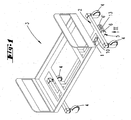
- FIG. 1 shows a perspective view of a hospital bed 3 with a chassis 2 and an additional roller 1 arranged thereon, but an accumulator and various controls have not been shown.
- the additional role 1 can be arranged between the rollers 4 of the head or foot of the hospital bed 3. But it is also conceivable that the additional roller 1 is fixed centrally to the four respectively arranged at the corners of the chassis 2 rollers 4 on the chassis 2.
- the additional roller 1 is in each case preferably oriented such that the running direction of the auxiliary roller 1 runs parallel to the longitudinal extent of the hospital bed 3.
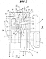
- the additional roll 1 is received in a frame 5, which consists in the embodiment of two mutually parallel frame walls 6, 6 '. Between the frame walls 6, 6 ', the auxiliary roller 1 is arranged. Like in the FIG. 2 can be clearly seen, the additional role 1 off-center, namely closer to the frame wall 6 'arranged. This is a favorable nesting achieved with the other units still described.
- the direction of the additional roller 1 is parallel to the frame walls 6, 6 '.
- the shaft 7 of the auxiliary roller 1 is stored in stock by the frame wall 6 without passing through them, and passes through the frame wall 6 ', wherein here also a storage is realized.
- the shaft 7 is fixedly connected to the auxiliary roller 1.
- the protruding from the frame wall 6 'end of the shaft 7 is connected to a gear 8, via which gear 8, a drive motor 9, the auxiliary roller 1 drives.
- the transmission 8 and the drive motor 9 are fixed from the outside to the frame wall 6 '.
- the drive motor 9 is an electric motor.
- the transmission 8 is designed so that it is not self-locking and has the lowest possible internal friction. Hereby, a freewheel effect can be achieved.
- a plug connection 35 is provided on the transmission 8.
- a mounting plate 10 is provided.
- the mounting plate 10 between the frame walls 6, 6 ', whose the underside of the chassis of the hospital bed associated areas arranged.
- the frame 5 is pivotally connected by means of an axis 11 with the mounting plate 10 fixed in the installed state with the chassis of the hospital bed.
- the axis 11 is in the embodiment with the frame walls 6, 6 'screw-connected.
- the frame walls 6, 6 ' are connected not only by the axis 11 but also by the shaft 7 of the auxiliary roller 1.
- the frame 5 is also formed with cross connections 12, 13.
- a cross connection 12 is arranged in the vicinity of the auxiliary roller 1 and a further cross connection 13 in the form of an auxiliary sheet in the vicinity of the axis 11.
- the cross connection 12 is formed by a bolt which has a diameter-reduced portion 14.
- the bolt thus forms as it were a bracing between the frame walls 6, 6 '.
- the section 14 is assigned to the additional role 1.
- the cross-connection 13 is connected in the embodiment with the end faces of the frame walls 6,6 'by means of screws.
- holes 15 are formed in the mounting plate, which - are penetrated - in the embodiment - cylinder head bolts 16.
- the cylinder head bolts 16 are screw-retained in corresponding threaded bores 17 of the chassis 2.
- FIGS. 4 and 6 show a section through a bore 15 with inlaid cylinder head screw 16.
- the mounting plate 10 forms an open-edged recess 36 in the direction of the axis 11.
- the mounting plate 10 tapers in the region of the open-edged recess 36 and thus forms a sloping ceiling 37.
- This ceiling 37 projects beyond only a portion of the recess 36.
- the angle of the ceiling 37 is approximately 20 ° to the lying surface of the hospital bed 3.
- the recess 36 is arranged centrally in the mounting plate 10 and is about half as wide as the total width of the mounting plate 10 is (see FIG. 2 ).
- an end portion 38 of a support arm 18 is inserted in the recess 36.
- the end portion 38 is conformed to the width of the recess 36.
- the substantial width of the support arm 18 is wider than the width of the recess 36 and so the support arm 18 forms lateral shoulders 39 which rest on the mounting plate 10.
- the support arm 18 is fixedly connected to the mounting plate 10 by the axle 11.
- the shoulders 39 contribute to the fact that the support arm 18 is rigidly connected to the mounting plate 10.
- the support arm 18 has approximately a right angle to the mounting plate 10 and projects into the space between the two frame walls 6,6 '.
- an annular body 19 is arranged, which is rotatable according to the outer ring of a ball bearing on balls. Specifically, this is a storage of the balls and the ring body 19 receiving axis between two legs 40 is provided.
- an eccentric 20 cooperates with the annular body 19.
- the annular body 19 allows a rolling with respect to the eccentric 20.
- the eccentric 20 is, in the embodiment centered, between the frame walls 6,6 'arranged on a shaft 21.
- the shaft end which is associated with the frame wall 6, is part of a transmission 22.
- the shaft 21 can be driven by the pivoting drive 23.
- the pivot drive 23 and the gear 22 are mounted on the inside of the frame wall 6 and together form the pivot unit for the auxiliary roller 1.
- the pivot drive 23 is connected via a cable 24 with a power source, by means of an intermediate control device connected.
- the pivot drive 23 extends laterally along the auxiliary roller 1. The arrangement in a juxtaposition of the auxiliary roller 1 and the pivot drive 23 can be a favorable size of the frame 5 can be achieved.
- the two axes of symmetry of the pivoting drive 23 and the drive motor 9 are approximately parallel to each other.
- the symmetry axes of the shafts 7, 21 of the additional roller 1 and the eccentric 20 extend approximately at right angles to one another (see FIG. 2).
- a pressure lever 25 is provided.
- the pressure lever 25 is located directly in the pivoting path of the eccentric 20 or in the narrower sense of the shaft 21 when the frame 5 is pivoted.
- The is supported by a spring 27 which on the one hand rests against the chassis of the hospital bed or specifically in the embodiment of the mounting plate 10 and on the other hand - by means of the pressure lever 25 - on the eccentric 20.
- the pressure lever 25 is the embodiment further supported on the support arm 18.
- the support arm 18, on the chassis side, a recess 41, and an axis 11 which passes through the pressure lever 25 at the foot.
- the pressure lever 25 also has an annular body 26 on the eccentric side. Accordingly, the annular body 26 is supported by balls, not shown, corresponding to a ball bearing on the end of the pressure lever 25.
- the pressure lever 25 is urged by the spring 27 in a counterclockwise direction with respect to FIGS. 4 and 6 , charged. It is obvious that the pressure lever 25 thus always bears against the eccentric 20, while this need not be necessary for the support arm 18, cf. FIG. 6 , In this respect, the pressure lever 25 acts together with the spring 27 in the sense of a shock absorber. The movement of the auxiliary roller 1 on the ground, ie in the lowered position, can thereby be compensated and damped (relative to movements in the vertical direction).
- one end of the compression spring 27 is received in a receiving cavity 28 of the pressure lever 25.
- the other end of the spring 27 is located in a receiving cavity 29 of the ceiling 37 of the recess 36 of the mounting plate 10 a.
- a sensor 30 is arranged laterally on the support arm 18.
- the sensor 30 may be, for example, an inductive proximity switch.
- a necessary for the sensor 30 connecting cable 31 is mounted on the side of the auxiliary roller 1 of the sensor 30. This connection cable 31 is subsequently passed through a bore 32, which runs parallel to the mounting plate 10.
- the sensor 30 is arranged at the height of the cross connection 13 (see FIGS. 4 and 6 ).
- the shafts 7,21 are received by ball bearings, which have not been shown in the drawings.
- the ball bearings lie in receiving holes in the frame walls 6,6 'of the frame 5 a.
- the additional role 1 in the release position.
- the additional role 1 is limited in the direction of the release position by the stopper pin 33, which abuts against the mounting plate 10.
- the auxiliary roller 1 is spaced from the floor 34.
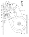
- the drive direction of the auxiliary roller 1 can be selected by a directional switch, and then the auxiliary roller 1 can be moved into its ground contact position by a push-button (FIG. FIG. 6 ) are relocated.
- the button By pressing the button, the pivoting drive 23 is started, so that the eccentric 20 from the position in FIG. 4 in the position in FIG. 6 relocated.
- FIG. 4 (Release position) is the range of the largest dimension (the distance of the outer periphery of the eccentric disc to the axial center of the eccentric axis) of the eccentric 20 to the annular body 19 of the support arm 18 at.
- the annular body 26 of the pressure lever 25 abuts the eccentric 20 and has a much smaller distance to the axis of symmetry of the shaft 21 than the annular body 19, in a peripheral region which is near or at the smallest distance to the eccentric axis.
- the FIG. 5 shows an intermediate position.
- the eccentric 20 was displaced by means of the pivoting drive 23 in the counterclockwise direction.
- the region of the largest dimension of the eccentric 20 bears against the annular body 26 of the pressure lever 25.
- the shaft 21 has a much smaller distance to the annular body 19, wherein the eccentric 20 and the annular body 19 is preferred do not touch.
- the eccentric 20 has a certain distance from the annular body 19 of the support arm 18.
- a "springing" of the auxiliary roll 1 is achieved, that when unevenness in the floor 34 occur, the spring 27, the additional roll 1 can shift further counterclockwise, so that there is always a ground contact of the auxiliary roll 1.
- the spring 27 compensates for the unevenness in the floor 34.
- the additional drive falls away by the drive motor 9 and the pivot drive moves the eccentric 20 in the position that in the FIG. 4 has been shown.
- the eccentric 20 runs on the annular body 19 and increases the distance between the axis of the annular body 19 and the axis of the shaft 21.
- the frame 5 is pivoted about the axis 11 in the direction of the release position.
Landscapes
- Engineering & Computer Science (AREA)
- Chemical & Material Sciences (AREA)
- Combustion & Propulsion (AREA)
- Transportation (AREA)
- Mechanical Engineering (AREA)
- Health & Medical Sciences (AREA)
- Nursing (AREA)
- Life Sciences & Earth Sciences (AREA)
- Animal Behavior & Ethology (AREA)
- General Health & Medical Sciences (AREA)
- Public Health (AREA)
- Veterinary Medicine (AREA)
- Invalid Beds And Related Equipment (AREA)
Priority Applications (3)
| Application Number | Priority Date | Filing Date | Title |
|---|---|---|---|
| EP10194524.4A EP2301506B1 (de) | 2006-02-17 | 2007-02-08 | In einem starren Rahmen gelagerte Zusatzrolle |
| DK10194524.4T DK2301506T3 (en) | 2006-02-17 | 2007-02-08 | Auxiliary roller enclosed in a fixed frame |
| PL07704448T PL1983959T3 (pl) | 2006-02-17 | 2007-02-08 | Łóżko szpitalne z podwoziem |
Applications Claiming Priority (2)
| Application Number | Priority Date | Filing Date | Title |
|---|---|---|---|
| DE102006007377A DE102006007377A1 (de) | 2006-02-17 | 2006-02-17 | Krankenhausbett mit einer weiteren in Bodenkontakt bringbaren wahlweise antreibbaren Zusatzrolle |
| PCT/EP2007/051195 WO2007093549A1 (de) | 2006-02-17 | 2007-02-08 | Krankenhausbett mit einer weiteren in bodenkontakt bringbaren wahlweise antreibbaren zusatzrolle |
Related Child Applications (2)
| Application Number | Title | Priority Date | Filing Date |
|---|---|---|---|
| EP10194524.4A Division EP2301506B1 (de) | 2006-02-17 | 2007-02-08 | In einem starren Rahmen gelagerte Zusatzrolle |
| EP10194524.4A Division-Into EP2301506B1 (de) | 2006-02-17 | 2007-02-08 | In einem starren Rahmen gelagerte Zusatzrolle |
Publications (2)
| Publication Number | Publication Date |
|---|---|
| EP1983959A1 EP1983959A1 (de) | 2008-10-29 |
| EP1983959B1 true EP1983959B1 (de) | 2015-10-28 |
Family
ID=38015244
Family Applications (2)
| Application Number | Title | Priority Date | Filing Date |
|---|---|---|---|
| EP07704448.5A Not-in-force EP1983959B1 (de) | 2006-02-17 | 2007-02-08 | Krankenhausbett mit einer weiteren in Bodenkontakt bringbaren wahlweise antreibbaren Zusatzrolle. |
| EP10194524.4A Active EP2301506B1 (de) | 2006-02-17 | 2007-02-08 | In einem starren Rahmen gelagerte Zusatzrolle |
Family Applications After (1)
| Application Number | Title | Priority Date | Filing Date |
|---|---|---|---|
| EP10194524.4A Active EP2301506B1 (de) | 2006-02-17 | 2007-02-08 | In einem starren Rahmen gelagerte Zusatzrolle |
Country Status (12)
| Country | Link |
|---|---|
| US (1) | US8662217B2 (enExample) |
| EP (2) | EP1983959B1 (enExample) |
| JP (1) | JP4887380B2 (enExample) |
| CN (2) | CN101384235B (enExample) |
| AU (1) | AU2007216572B2 (enExample) |
| CA (1) | CA2640666C (enExample) |
| DE (1) | DE102006007377A1 (enExample) |
| DK (2) | DK2301506T3 (enExample) |
| ES (2) | ES2553884T3 (enExample) |
| PL (2) | PL1983959T3 (enExample) |
| PT (1) | PT2301506T (enExample) |
| WO (1) | WO2007093549A1 (enExample) |
Families Citing this family (31)
| Publication number | Priority date | Publication date | Assignee | Title |
|---|---|---|---|---|
| US20120280464A1 (en) * | 2008-10-27 | 2012-11-08 | Nelson Richard L | Adjustable load-bearing wheels and kits for patient lifters |
| US8746710B2 (en) * | 2010-05-17 | 2014-06-10 | Linet Spol S.R.O. | Patient support apparatus having an auxiliary wheel |
| US20120198620A1 (en) * | 2011-02-08 | 2012-08-09 | Hornbach David W | Motorized center wheel deployment mechanism for a patient support |
| DE102011000817A1 (de) | 2011-02-18 | 2012-08-23 | Tente Gmbh & Co. Kg | Zusatzrolle |
| FR2976892B1 (fr) * | 2011-06-21 | 2014-09-05 | Renault Sa | Chariot de transport pourvu d'un moyen d'assistance a la manoeuvre |
| CZ309134B6 (cs) * | 2012-08-29 | 2022-02-23 | Linet, Spol. S R.O. | Systém pro pohánění nemocničního lůžka |
| US9849723B2 (en) * | 2013-06-06 | 2017-12-26 | Rene LAFEVER | Adjustable height platform |
| DE102014108002A1 (de) | 2013-06-19 | 2014-12-24 | Tente Gmbh & Co. Kg | Rolle mit angetriebenem Rad, Lastenwagen mit ein angetriebenes Rad aufweisender Rolle und Bediengerät |
| DK3025407T3 (da) | 2013-07-22 | 2019-12-09 | Linak As | Actuator system |
| DE102014100056A1 (de) | 2013-11-18 | 2015-05-21 | Tente Gmbh & Co. Kg | Steuerung von an einem Verfahrteil angebrachten Rollen |
| DE202013105191U1 (de) | 2013-11-18 | 2015-02-19 | Tente Gmbh & Co. Kg | Steuerung von an einem Verfahrteil angebrachten Rollen |
| FR3017358B1 (fr) * | 2014-02-11 | 2016-02-19 | Coutier Ind S A R L | Ensemble de motorisation d'une base roulante |
| US9603764B2 (en) | 2014-02-11 | 2017-03-28 | Medline Industries, Inc. | Method and apparatus for a locking caster |
| US9918888B2 (en) | 2014-03-21 | 2018-03-20 | Medline Industries, Inc. | Locking mechanism with pivotable foot actuation lever |
| DE102014107973A1 (de) | 2014-06-05 | 2015-12-17 | Tente Gmbh & Co. Kg | Mit zwei motorisch angetriebenen Laufrädern und einer Steuerung versehener Lastwagen |
| AU2016286278B2 (en) | 2015-06-29 | 2020-05-14 | Arjohuntleigh Ab | Brake assistance system for patient handling equipment |
| MX395404B (es) * | 2015-06-29 | 2025-03-25 | Arjohuntleigh Ab | Mecanismo de accionamiento de rueda para equipo de manejo de pacientes. |
| US10377403B2 (en) * | 2015-11-06 | 2019-08-13 | Caster Concepts, Inc. | Powered utility cart and compliant drive wheel therefor |
| CN109475456B (zh) * | 2016-07-15 | 2021-03-05 | 福特全球技术公司 | 辅助动力装置 |
| US11071662B2 (en) | 2017-12-28 | 2021-07-27 | Stryker Corporation | Patient transport apparatus with controlled auxiliary wheel speed |
| US10799403B2 (en) | 2017-12-28 | 2020-10-13 | Stryker Corporation | Patient transport apparatus with controlled auxiliary wheel deployment |
| US11304860B2 (en) | 2018-11-21 | 2022-04-19 | Stryker Corporation | Patient transport apparatus with auxiliary wheel system |
| US11484447B2 (en) | 2018-11-21 | 2022-11-01 | Stryker Corporation | Patient transport apparatus with controlled auxiliary wheel deployment |
| US12178757B2 (en) | 2019-12-30 | 2024-12-31 | Stryker Corporation | Patient transport apparatus with auxiliary wheel control systems |
| US11806296B2 (en) | 2019-12-30 | 2023-11-07 | Stryker Corporation | Patient transport apparatus with controlled auxiliary wheel speed |
| NL2025624B1 (nl) * | 2020-05-19 | 2021-12-07 | B M Innovaties B V | Inrichting voor het aandrijven van een verrijdbaar object |
| AU2022254928A1 (en) * | 2021-04-09 | 2023-10-05 | Arjo IP Holding Aktiebolag | A patient transfer device |
| EP4329694A1 (de) | 2021-04-30 | 2024-03-06 | Tente GmbH & Co. KG | Steuerung sowie verfahren zur steuerung von an einem verfahrteil angebrachten rollen |
| DE102022106363A1 (de) | 2021-04-30 | 2022-11-03 | Tente Gmbh & Co. Kg | Steuerung sowie Verfahren zur Steuerung von an einem Verfahrteil angebrachten Rollen |
| SE546827C2 (en) * | 2021-10-11 | 2025-02-25 | Mercado Medic Ab | A personal movable chair, and a method for controlling said chair |
| CN117297894A (zh) * | 2022-06-23 | 2023-12-29 | 毕威泰克(浙江)医疗器械有限公司 | 电动辅助驱动装置及具有其的病床 |
Family Cites Families (29)
| Publication number | Priority date | Publication date | Assignee | Title |
|---|---|---|---|---|
| JPS60122561A (ja) * | 1983-12-06 | 1985-07-01 | 株式会社今仙電機製作所 | 搬送器具 |
| CN2030480U (zh) * | 1988-01-16 | 1989-01-11 | 连勇 | 一种体育健身、按摩两用床 |
| CA2010543A1 (en) | 1989-03-17 | 1990-09-17 | Ryan A. Reeder | Motorized stretcher |
| US5083625A (en) | 1990-07-02 | 1992-01-28 | Bleicher Joel N | Powdered maneuverable hospital cart |
| US5135063A (en) | 1990-08-30 | 1992-08-04 | Smucker Manufacturing, Inc. | Power unit for driving manually-operated wheelchair |
| US5222567A (en) * | 1991-04-26 | 1993-06-29 | Genus Inc. | Power assist device for a wheelchair |
| FR2735019B1 (fr) | 1995-06-09 | 1997-11-28 | Corona Soc | Element mobile, en particulier lit d'hospitalisation, prenant appui sur le sol par plusieurs roues de sustentation orientables |
| US5984615A (en) * | 1996-03-04 | 1999-11-16 | Sundseth; Jarl Gailon | Roller drive unit |
| US6000486A (en) * | 1997-04-18 | 1999-12-14 | Medicart, L.L.C. | Apparatus for providing self-propelled motion to medication carts |
| JP3267631B2 (ja) * | 1997-06-06 | 2002-03-18 | ミサワホーム株式会社 | 車椅子 |
| US6209670B1 (en) * | 1998-11-16 | 2001-04-03 | Sunnybrook & Women's College Health Science Centre | Clutch for multi-directional transportation device |
| US6330926B1 (en) | 1999-09-15 | 2001-12-18 | Hill-Rom Services, Inc. | Stretcher having a motorized wheel |
| US6772850B1 (en) * | 2000-01-21 | 2004-08-10 | Stryker Corporation | Power assisted wheeled carriage |
| CN101791261B (zh) * | 2000-05-11 | 2013-04-24 | 希尔-罗姆服务股份有限公司 | 病人支撑台的机动牵引装置 |
| DE10120316C1 (de) * | 2001-04-26 | 2002-08-08 | Voelker Moebelproduktionsgmbh | Bett, insbesondere Kranken- oder Pflegebett |
| US6752224B2 (en) | 2002-02-28 | 2004-06-22 | Stryker Corporation | Wheeled carriage having a powered auxiliary wheel, auxiliary wheel overtravel, and an auxiliary wheel drive and control system |
| JP2004194844A (ja) * | 2002-12-17 | 2004-07-15 | Paramount Bed Co Ltd | ベッドにおける電動搬送装置およびその駆動制御方法 |
| US6725956B1 (en) | 2003-05-06 | 2004-04-27 | Stryker Corporation | Fifth wheel for bed |
| IL158683A0 (en) * | 2003-10-30 | 2004-05-12 | Savion Ind 1987 Ltd | Power-driven maneuverable platform |
| NL1025473C2 (nl) * | 2004-02-12 | 2005-08-16 | Reich Gmbh | Manoeuvreerinrichting en aanhanger voorzien van manoeuvreerinrichting. |
| US6880661B1 (en) * | 2004-02-26 | 2005-04-19 | Steve Oh | Detachable motor drive for a bicycle |
| JP4471744B2 (ja) * | 2004-06-16 | 2010-06-02 | パラマウントベッド株式会社 | ベッド電動搬送装置及びその駆動制御方法 |
| CN1732875B (zh) * | 2004-08-10 | 2010-06-16 | 医疗器具澳大利亚有限公司 | 驱动轮组件 |
| WO2006074473A2 (en) * | 2005-01-10 | 2006-07-13 | Livengood Engineering, Inc. | Modular patient support system |
| US7419019B1 (en) * | 2006-03-23 | 2008-09-02 | Safe-T-Care Manufacturing, Co., Inc. | Power assist apparatus for use with a hospital bed |
| US7882582B2 (en) * | 2006-10-13 | 2011-02-08 | Hill-Rom Services, Inc. | User interface and control system for powered transport device of a patient support apparatus |
| CZ17216U1 (cs) * | 2006-11-09 | 2007-02-05 | Linet, Spol. S R. O. | Sestava vodicího kolecka, zejména pro nemocnicní luzko |
| US7721875B2 (en) * | 2007-06-14 | 2010-05-25 | Goodrich Corporation | Power drive unit with eccentric roller lift system |
| JP5305810B2 (ja) * | 2008-09-26 | 2013-10-02 | 愛知機械テクノシステム株式会社 | 無人搬送車 |
-
2006
- 2006-02-17 DE DE102006007377A patent/DE102006007377A1/de not_active Withdrawn
-
2007
- 2007-02-08 ES ES07704448.5T patent/ES2553884T3/es active Active
- 2007-02-08 WO PCT/EP2007/051195 patent/WO2007093549A1/de not_active Ceased
- 2007-02-08 EP EP07704448.5A patent/EP1983959B1/de not_active Not-in-force
- 2007-02-08 JP JP2008554744A patent/JP4887380B2/ja not_active Expired - Fee Related
- 2007-02-08 CA CA2640666A patent/CA2640666C/en not_active Expired - Fee Related
- 2007-02-08 AU AU2007216572A patent/AU2007216572B2/en not_active Ceased
- 2007-02-08 ES ES10194524.4T patent/ES2621783T3/es active Active
- 2007-02-08 EP EP10194524.4A patent/EP2301506B1/de active Active
- 2007-02-08 PL PL07704448T patent/PL1983959T3/pl unknown
- 2007-02-08 PT PT101945244T patent/PT2301506T/pt unknown
- 2007-02-08 PL PL10194524T patent/PL2301506T3/pl unknown
- 2007-02-08 US US12/224,069 patent/US8662217B2/en active Active
- 2007-02-08 CN CN2007800051849A patent/CN101384235B/zh active Active
- 2007-02-08 DK DK10194524.4T patent/DK2301506T3/en active
- 2007-02-08 CN CN201110023452.8A patent/CN102106776B/zh active Active
- 2007-02-08 DK DK07704448.5T patent/DK1983959T3/en active
Also Published As
| Publication number | Publication date |
|---|---|
| EP2301506B1 (de) | 2017-02-15 |
| EP1983959A1 (de) | 2008-10-29 |
| DE102006007377A1 (de) | 2007-08-30 |
| CN102106776B (zh) | 2014-05-28 |
| ES2553884T3 (es) | 2015-12-14 |
| CN101384235B (zh) | 2011-04-27 |
| US20100181122A1 (en) | 2010-07-22 |
| PL2301506T3 (pl) | 2017-07-31 |
| EP2301506A1 (de) | 2011-03-30 |
| CN101384235A (zh) | 2009-03-11 |
| US8662217B2 (en) | 2014-03-04 |
| CN102106776A (zh) | 2011-06-29 |
| ES2621783T3 (es) | 2017-07-05 |
| DK1983959T3 (en) | 2016-02-08 |
| JP2009526584A (ja) | 2009-07-23 |
| WO2007093549A1 (de) | 2007-08-23 |
| PL1983959T3 (pl) | 2016-02-29 |
| PT2301506T (pt) | 2017-05-10 |
| CA2640666C (en) | 2014-10-14 |
| DK2301506T3 (en) | 2017-05-22 |
| AU2007216572B2 (en) | 2011-07-07 |
| JP4887380B2 (ja) | 2012-02-29 |
| CA2640666A1 (en) | 2007-08-23 |
| AU2007216572A1 (en) | 2007-08-23 |
Similar Documents
| Publication | Publication Date | Title |
|---|---|---|
| EP1983959B1 (de) | Krankenhausbett mit einer weiteren in Bodenkontakt bringbaren wahlweise antreibbaren Zusatzrolle. | |
| EP0466065B1 (de) | Lastförderfahrzeug | |
| EP2675416B1 (de) | Zusatzrolle | |
| EP0383254B1 (de) | Hubwagen mit einer in vertikaler Richtung federbelasteten vorgespannten Antriebseinheit | |
| EP2452664B1 (de) | Operationstisch | |
| DE102017108064A1 (de) | Schwenkverriegelungsvorrichtung sowie Hebevorrichtung mit einer Schwenkverriegelungsvorrichtung | |
| DE10347571A1 (de) | Druckwerk | |
| DE60308400T2 (de) | Rollenbahnvorrichtung zum bewegen einer last in einer im wesentlichen horizontalen ebene | |
| WO2012155280A1 (de) | Gerätestütze | |
| DE60315951T2 (de) | Radhubmechanismus | |
| DE1605068C3 (de) | Zugmaschine für die Verwendung auf Schiene und Straße | |
| WO2011009537A1 (de) | Fahrzeug mit ausschwenkbarem mastarmaufbau | |
| DE202019107144U1 (de) | Ausfahrbare Trittstufe | |
| DE10347573A1 (de) | Druckwerk und ein Verfahren zum Bewegen eines Gestellteils | |
| DE102013100073A1 (de) | Flurförderzeug mit zumindest einer gefederten Stützrolle | |
| DE10131559A1 (de) | Vorrichtung zur Bodendruckentlastung von am Erdboden arbeitenden Arbeitsgeräten | |
| DE602004006963T2 (de) | Stabilisatorbein für einen lastwagen | |
| EP3449887B1 (de) | Fussteil für einen eine stützsäule und eine patientenlagerfläche aufweisenden operationstisch | |
| WO2018050691A1 (de) | Über ein schaltgestänge zu betätigende rollen sowie verfahrwagen mit zwei rollenpaaren | |
| DE102008006169A1 (de) | Elektrohängebahn | |
| DE19626119A1 (de) | Rangierwagenheber | |
| EP4403345B1 (de) | Pendelarm für einen walzenverdichter zum verdichten von abfallstoffen | |
| DE102013100074A9 (de) | Flurförderzeug mit zumindest einer gefederten Stützrolle in einem Antriebsteil | |
| DE102014003488A1 (de) | Lenkabnahme und Schwerlast-Transportfahrzeug | |
| DE19839384C1 (de) | Zugmaschine |
Legal Events
| Date | Code | Title | Description |
|---|---|---|---|
| PUAI | Public reference made under article 153(3) epc to a published international application that has entered the european phase |
Free format text: ORIGINAL CODE: 0009012 |
|
| 17P | Request for examination filed |
Effective date: 20080827 |
|
| AK | Designated contracting states |
Kind code of ref document: A1 Designated state(s): AT BE BG CH CY CZ DE DK EE ES FI FR GB GR HU IE IS IT LI LT LU LV MC NL PL PT RO SE SI SK TR |
|
| RIN1 | Information on inventor provided before grant (corrected) |
Inventor name: HOFRICHTER, GUENTHER Inventor name: BLOCK, WOLFGANG |
|
| DAX | Request for extension of the european patent (deleted) | ||
| 17Q | First examination report despatched |
Effective date: 20121127 |
|
| GRAP | Despatch of communication of intention to grant a patent |
Free format text: ORIGINAL CODE: EPIDOSNIGR1 |
|
| INTG | Intention to grant announced |
Effective date: 20150519 |
|
| GRAS | Grant fee paid |
Free format text: ORIGINAL CODE: EPIDOSNIGR3 |
|
| GRAA | (expected) grant |
Free format text: ORIGINAL CODE: 0009210 |
|
| AK | Designated contracting states |
Kind code of ref document: B1 Designated state(s): AT BE BG CH CY CZ DE DK EE ES FI FR GB GR HU IE IS IT LI LT LU LV MC NL PL PT RO SE SI SK TR |
|
| REG | Reference to a national code |
Ref country code: GB Ref legal event code: FG4D Free format text: NOT ENGLISH |
|
| REG | Reference to a national code |
Ref country code: CH Ref legal event code: EP Ref country code: CH Ref legal event code: NV Representative=s name: R. A. EGLI AND CO. PATENTANWAELTE, CH |
|
| REG | Reference to a national code |
Ref country code: AT Ref legal event code: REF Ref document number: 757525 Country of ref document: AT Kind code of ref document: T Effective date: 20151115 |
|
| REG | Reference to a national code |
Ref country code: IE Ref legal event code: FG4D Free format text: LANGUAGE OF EP DOCUMENT: GERMAN |
|
| REG | Reference to a national code |
Ref country code: DE Ref legal event code: R096 Ref document number: 502007014346 Country of ref document: DE |
|
| REG | Reference to a national code |
Ref country code: ES Ref legal event code: FG2A Ref document number: 2553884 Country of ref document: ES Kind code of ref document: T3 Effective date: 20151214 |
|
| REG | Reference to a national code |
Ref country code: SE Ref legal event code: TRGR |
|
| REG | Reference to a national code |
Ref country code: FR Ref legal event code: PLFP Year of fee payment: 10 |
|
| REG | Reference to a national code |
Ref country code: DK Ref legal event code: T3 Effective date: 20160201 |
|
| REG | Reference to a national code |
Ref country code: LT Ref legal event code: MG4D |
|
| REG | Reference to a national code |
Ref country code: NL Ref legal event code: FP |
|
| PG25 | Lapsed in a contracting state [announced via postgrant information from national office to epo] |
Ref country code: IS Free format text: LAPSE BECAUSE OF FAILURE TO SUBMIT A TRANSLATION OF THE DESCRIPTION OR TO PAY THE FEE WITHIN THE PRESCRIBED TIME-LIMIT Effective date: 20160228 Ref country code: LT Free format text: LAPSE BECAUSE OF FAILURE TO SUBMIT A TRANSLATION OF THE DESCRIPTION OR TO PAY THE FEE WITHIN THE PRESCRIBED TIME-LIMIT Effective date: 20151028 |
|
| PG25 | Lapsed in a contracting state [announced via postgrant information from national office to epo] |
Ref country code: LV Free format text: LAPSE BECAUSE OF FAILURE TO SUBMIT A TRANSLATION OF THE DESCRIPTION OR TO PAY THE FEE WITHIN THE PRESCRIBED TIME-LIMIT Effective date: 20151028 Ref country code: PT Free format text: LAPSE BECAUSE OF FAILURE TO SUBMIT A TRANSLATION OF THE DESCRIPTION OR TO PAY THE FEE WITHIN THE PRESCRIBED TIME-LIMIT Effective date: 20160229 Ref country code: GR Free format text: LAPSE BECAUSE OF FAILURE TO SUBMIT A TRANSLATION OF THE DESCRIPTION OR TO PAY THE FEE WITHIN THE PRESCRIBED TIME-LIMIT Effective date: 20160129 |
|
| REG | Reference to a national code |
Ref country code: DE Ref legal event code: R097 Ref document number: 502007014346 Country of ref document: DE |
|
| PG25 | Lapsed in a contracting state [announced via postgrant information from national office to epo] |
Ref country code: SK Free format text: LAPSE BECAUSE OF FAILURE TO SUBMIT A TRANSLATION OF THE DESCRIPTION OR TO PAY THE FEE WITHIN THE PRESCRIBED TIME-LIMIT Effective date: 20151028 Ref country code: EE Free format text: LAPSE BECAUSE OF FAILURE TO SUBMIT A TRANSLATION OF THE DESCRIPTION OR TO PAY THE FEE WITHIN THE PRESCRIBED TIME-LIMIT Effective date: 20151028 Ref country code: RO Free format text: LAPSE BECAUSE OF FAILURE TO SUBMIT A TRANSLATION OF THE DESCRIPTION OR TO PAY THE FEE WITHIN THE PRESCRIBED TIME-LIMIT Effective date: 20151028 |
|
| PLBE | No opposition filed within time limit |
Free format text: ORIGINAL CODE: 0009261 |
|
| STAA | Information on the status of an ep patent application or granted ep patent |
Free format text: STATUS: NO OPPOSITION FILED WITHIN TIME LIMIT |
|
| PG25 | Lapsed in a contracting state [announced via postgrant information from national office to epo] |
Ref country code: MC Free format text: LAPSE BECAUSE OF FAILURE TO SUBMIT A TRANSLATION OF THE DESCRIPTION OR TO PAY THE FEE WITHIN THE PRESCRIBED TIME-LIMIT Effective date: 20151028 Ref country code: LU Free format text: LAPSE BECAUSE OF FAILURE TO SUBMIT A TRANSLATION OF THE DESCRIPTION OR TO PAY THE FEE WITHIN THE PRESCRIBED TIME-LIMIT Effective date: 20160208 |
|
| 26N | No opposition filed |
Effective date: 20160729 |
|
| PG25 | Lapsed in a contracting state [announced via postgrant information from national office to epo] |
Ref country code: SI Free format text: LAPSE BECAUSE OF FAILURE TO SUBMIT A TRANSLATION OF THE DESCRIPTION OR TO PAY THE FEE WITHIN THE PRESCRIBED TIME-LIMIT Effective date: 20151028 |
|
| REG | Reference to a national code |
Ref country code: IE Ref legal event code: MM4A |
|
| PG25 | Lapsed in a contracting state [announced via postgrant information from national office to epo] |
Ref country code: IE Free format text: LAPSE BECAUSE OF NON-PAYMENT OF DUE FEES Effective date: 20160208 |
|
| REG | Reference to a national code |
Ref country code: FR Ref legal event code: PLFP Year of fee payment: 11 |
|
| PGFP | Annual fee paid to national office [announced via postgrant information from national office to epo] |
Ref country code: PL Payment date: 20161202 Year of fee payment: 11 |
|
| REG | Reference to a national code |
Ref country code: AT Ref legal event code: MM01 Ref document number: 757525 Country of ref document: AT Kind code of ref document: T Effective date: 20160208 |
|
| PGFP | Annual fee paid to national office [announced via postgrant information from national office to epo] |
Ref country code: CH Payment date: 20170221 Year of fee payment: 11 Ref country code: FI Payment date: 20170217 Year of fee payment: 11 Ref country code: SE Payment date: 20170221 Year of fee payment: 11 |
|
| PG25 | Lapsed in a contracting state [announced via postgrant information from national office to epo] |
Ref country code: AT Free format text: LAPSE BECAUSE OF NON-PAYMENT OF DUE FEES Effective date: 20160208 |
|
| PGFP | Annual fee paid to national office [announced via postgrant information from national office to epo] |
Ref country code: NL Payment date: 20170217 Year of fee payment: 11 Ref country code: DK Payment date: 20170221 Year of fee payment: 11 Ref country code: BE Payment date: 20170217 Year of fee payment: 11 |
|
| REG | Reference to a national code |
Ref country code: FR Ref legal event code: PLFP Year of fee payment: 12 |
|
| PGFP | Annual fee paid to national office [announced via postgrant information from national office to epo] |
Ref country code: ES Payment date: 20180319 Year of fee payment: 12 Ref country code: GB Payment date: 20180216 Year of fee payment: 12 |
|
| PG25 | Lapsed in a contracting state [announced via postgrant information from national office to epo] |
Ref country code: CY Free format text: LAPSE BECAUSE OF FAILURE TO SUBMIT A TRANSLATION OF THE DESCRIPTION OR TO PAY THE FEE WITHIN THE PRESCRIBED TIME-LIMIT Effective date: 20151028 Ref country code: HU Free format text: LAPSE BECAUSE OF FAILURE TO SUBMIT A TRANSLATION OF THE DESCRIPTION OR TO PAY THE FEE WITHIN THE PRESCRIBED TIME-LIMIT; INVALID AB INITIO Effective date: 20070208 |
|
| PGFP | Annual fee paid to national office [announced via postgrant information from national office to epo] |
Ref country code: FR Payment date: 20180221 Year of fee payment: 12 |
|
| PG25 | Lapsed in a contracting state [announced via postgrant information from national office to epo] |
Ref country code: BG Free format text: LAPSE BECAUSE OF FAILURE TO SUBMIT A TRANSLATION OF THE DESCRIPTION OR TO PAY THE FEE WITHIN THE PRESCRIBED TIME-LIMIT Effective date: 20151028 |
|
| REG | Reference to a national code |
Ref country code: CH Ref legal event code: PL |
|
| REG | Reference to a national code |
Ref country code: DK Ref legal event code: EBP Effective date: 20180228 |
|
| REG | Reference to a national code |
Ref country code: SE Ref legal event code: EUG |
|
| REG | Reference to a national code |
Ref country code: NL Ref legal event code: MM Effective date: 20180301 |
|
| PG25 | Lapsed in a contracting state [announced via postgrant information from national office to epo] |
Ref country code: FI Free format text: LAPSE BECAUSE OF NON-PAYMENT OF DUE FEES Effective date: 20180208 Ref country code: SE Free format text: LAPSE BECAUSE OF NON-PAYMENT OF DUE FEES Effective date: 20180209 |
|
| REG | Reference to a national code |
Ref country code: BE Ref legal event code: MM Effective date: 20180228 |
|
| PG25 | Lapsed in a contracting state [announced via postgrant information from national office to epo] |
Ref country code: LI Free format text: LAPSE BECAUSE OF NON-PAYMENT OF DUE FEES Effective date: 20180228 Ref country code: CH Free format text: LAPSE BECAUSE OF NON-PAYMENT OF DUE FEES Effective date: 20180228 |
|
| PG25 | Lapsed in a contracting state [announced via postgrant information from national office to epo] |
Ref country code: NL Free format text: LAPSE BECAUSE OF NON-PAYMENT OF DUE FEES Effective date: 20180301 |
|
| PG25 | Lapsed in a contracting state [announced via postgrant information from national office to epo] |
Ref country code: DK Free format text: LAPSE BECAUSE OF NON-PAYMENT OF DUE FEES Effective date: 20180228 |
|
| PG25 | Lapsed in a contracting state [announced via postgrant information from national office to epo] |
Ref country code: BE Free format text: LAPSE BECAUSE OF NON-PAYMENT OF DUE FEES Effective date: 20180228 |
|
| PGFP | Annual fee paid to national office [announced via postgrant information from national office to epo] |
Ref country code: CZ Payment date: 20190116 Year of fee payment: 13 Ref country code: IT Payment date: 20190226 Year of fee payment: 13 Ref country code: DE Payment date: 20190319 Year of fee payment: 13 |
|
| PGFP | Annual fee paid to national office [announced via postgrant information from national office to epo] |
Ref country code: TR Payment date: 20190208 Year of fee payment: 13 Ref country code: DE Payment date: 20190319 Year of fee payment: 13 |
|
| PG25 | Lapsed in a contracting state [announced via postgrant information from national office to epo] |
Ref country code: PL Free format text: LAPSE BECAUSE OF NON-PAYMENT OF DUE FEES Effective date: 20180208 |
|
| GBPC | Gb: european patent ceased through non-payment of renewal fee |
Effective date: 20190208 |
|
| PG25 | Lapsed in a contracting state [announced via postgrant information from national office to epo] |
Ref country code: GB Free format text: LAPSE BECAUSE OF NON-PAYMENT OF DUE FEES Effective date: 20190208 |
|
| PG25 | Lapsed in a contracting state [announced via postgrant information from national office to epo] |
Ref country code: FR Free format text: LAPSE BECAUSE OF NON-PAYMENT OF DUE FEES Effective date: 20190228 |
|
| REG | Reference to a national code |
Ref country code: ES Ref legal event code: FD2A Effective date: 20200327 |
|
| PG25 | Lapsed in a contracting state [announced via postgrant information from national office to epo] |
Ref country code: ES Free format text: LAPSE BECAUSE OF NON-PAYMENT OF DUE FEES Effective date: 20190209 |
|
| REG | Reference to a national code |
Ref country code: DE Ref legal event code: R119 Ref document number: 502007014346 Country of ref document: DE |
|
| PG25 | Lapsed in a contracting state [announced via postgrant information from national office to epo] |
Ref country code: CZ Free format text: LAPSE BECAUSE OF NON-PAYMENT OF DUE FEES Effective date: 20200208 |
|
| PG25 | Lapsed in a contracting state [announced via postgrant information from national office to epo] |
Ref country code: DE Free format text: LAPSE BECAUSE OF NON-PAYMENT OF DUE FEES Effective date: 20200901 |
|
| PG25 | Lapsed in a contracting state [announced via postgrant information from national office to epo] |
Ref country code: IT Free format text: LAPSE BECAUSE OF NON-PAYMENT OF DUE FEES Effective date: 20200208 |
|
| PG25 | Lapsed in a contracting state [announced via postgrant information from national office to epo] |
Ref country code: TR Free format text: LAPSE BECAUSE OF NON-PAYMENT OF DUE FEES Effective date: 20200208 |