EP1983959B1 - Krankenhausbett mit einer weiteren in Bodenkontakt bringbaren wahlweise antreibbaren Zusatzrolle. - Google Patents
Krankenhausbett mit einer weiteren in Bodenkontakt bringbaren wahlweise antreibbaren Zusatzrolle. Download PDFInfo
- Publication number
- EP1983959B1 EP1983959B1 EP07704448.5A EP07704448A EP1983959B1 EP 1983959 B1 EP1983959 B1 EP 1983959B1 EP 07704448 A EP07704448 A EP 07704448A EP 1983959 B1 EP1983959 B1 EP 1983959B1
- Authority
- EP
- European Patent Office
- Prior art keywords
- frame
- hospital bed
- eccentric
- chassis
- bed according
- Prior art date
- Legal status (The legal status is an assumption and is not a legal conclusion. Google has not performed a legal analysis and makes no representation as to the accuracy of the status listed.)
- Not-in-force
Links
Images


Classifications
-
- A—HUMAN NECESSITIES
- A61—MEDICAL OR VETERINARY SCIENCE; HYGIENE
- A61G—TRANSPORT, PERSONAL CONVEYANCES, OR ACCOMMODATION SPECIALLY ADAPTED FOR PATIENTS OR DISABLED PERSONS; OPERATING TABLES OR CHAIRS; CHAIRS FOR DENTISTRY; FUNERAL DEVICES
- A61G7/00—Beds specially adapted for nursing; Devices for lifting patients or disabled persons
- A61G7/08—Apparatus for transporting beds
-
- B—PERFORMING OPERATIONS; TRANSPORTING
- B62—LAND VEHICLES FOR TRAVELLING OTHERWISE THAN ON RAILS
- B62B—HAND-PROPELLED VEHICLES, e.g. HAND CARTS OR PERAMBULATORS; SLEDGES
- B62B5/00—Accessories or details specially adapted for hand carts
- B62B5/0026—Propulsion aids
-
- B—PERFORMING OPERATIONS; TRANSPORTING
- B62—LAND VEHICLES FOR TRAVELLING OTHERWISE THAN ON RAILS
- B62B—HAND-PROPELLED VEHICLES, e.g. HAND CARTS OR PERAMBULATORS; SLEDGES
- B62B5/00—Accessories or details specially adapted for hand carts
- B62B5/0026—Propulsion aids
- B62B5/0033—Electric motors
- B62B5/0036—Arrangements of motors
- B62B5/005—Detachably mounted motor units
-
- B—PERFORMING OPERATIONS; TRANSPORTING
- B62—LAND VEHICLES FOR TRAVELLING OTHERWISE THAN ON RAILS
- B62B—HAND-PROPELLED VEHICLES, e.g. HAND CARTS OR PERAMBULATORS; SLEDGES
- B62B5/00—Accessories or details specially adapted for hand carts
- B62B5/0026—Propulsion aids
- B62B5/0033—Electric motors
- B62B5/0036—Arrangements of motors
- B62B5/0043—One motor drives one wheel
Definitions
- the invention relates to a hospital bed with a chassis, with four mounted on the chassis rollers and at least one further brought into contact with the ground optionally driven auxiliary role, the additional role is stored on a rigid frame and together with the frame relative to the chassis by pivoting raised or lowered is, further provided a fixed to the frame drive motor for the additional role and a separate pivoting drive is provided for raising and lowering the additional role.
- the auxiliary roller is accommodated in a housing, which housing is pivotally connected to the chassis. At the free end of the housing engages a separate pivot drive, which is pivotally connected to the chassis.
- auxiliary roller and the drive motor are received by a housing which is mounted on one end of a leaf spring.
- the other end of the leaf spring is connected to the chassis.
- the leaf spring acts on the auxiliary roller in the direction of the floor.
- a mechanism is provided which engages and overhangs a housing protruding end of the leaf spring. The mechanism is firmly connected to the chassis. If the mechanism releases the leaf spring, the additional roller shifts in the direction of the floor.
- the invention has the object of providing a generic hospital bed as initially assumed advantageous to design.
- the pivoting drive, the auxiliary roller and the drive motor together with the frame form a unit.
- the frame also completely absorbs the weight of the pivoting drive.
- the unit can be mounted as a whole on a chassis of a hospital bed in the simplest way. This makes it possible, in the context of a workshop pre-assembly, already make the orientation of the rotary actuator, especially an eccentric, as described in detail below, with regard to the additional role.
- the unit of frame, drive motor and additional role is also advantageous in terms of upgrading existing hospital beds with such an additional role. Regardless or in addition to this, the compact design is an advantage. In addition, the fact that a concentration by weight is created. This can contribute to the stability of the hospital bed.
- the pivoting drive by means of an eccentric the frame relative to the chassis on which the eccentric is also supported moves. It is only a touching interaction so far with the chassis required, but for example no articulated connection. This can, as explained, but rather be realized independently thereof.
- the moving parts are reduced.
- the eccentric may be formed by an eccentric disc fixedly mounted on the shaft. The rotational movement for the eccentric is generated by the pivoting drive. If the arrangement is such that the axes of the pivoting drive and the eccentric intersect, a transmission is required to transmit the driving force from the pivoting drive to the eccentric. However, it is preferred that the axes or shafts are parallel or aligned in this respect.
- a drive shaft of the pivoting drive can for this purpose advantageously directly carry the already mentioned eccentric disc.
- a stop is given in relation to a ground contact position of the additional role.
- a comparatively rigid (in the printing direction of the additional role) interaction between the additional role and the chassis is given as it is the case with respect to the conventional roles in such a hospital bed anyway.
- the - only - eccentric support of the additional role on the chassis of the hospital bed can also be used to the effect that the eccentric rests in the ground contact position not directly to the chassis, but by mediating a balance part.
- Such a compensation part can be further preferably a spring part, which is supported on the one hand on the chassis and on the other hand on the additional role or specifically the eccentric.
- a compression spring biasing the frame (as a whole) into the lowered position is suitable. This spring then acts as a shock absorber when lowered, in contact with the ground additional role.
- said compression spring acts on the eccentric by means of a pressure lever applied to a chassis-fixed axis.
- the pressure lever can pivot about the same axis as the auxiliary roller. This is usually the same axis, which holds the frame pivotally on the chassis.
- a roller for example in the manner of a ball bearing ring, may be provided on the pressure lever or possibly also on the eccentric. It thus results in movement a favorable role transfer.
- the eccentric does not only interact with the chassis via the spring. Because this alone, the frame would be constantly in the lowered position. Raising and lowering, in addition, in addition, at least with respect to a certain portion of the lowering or lifting stroke, a rigid support of the eccentric relative to the chassis is required.
- a support arm is provided, with which - circumferentially offset relative to the eccentric to the interaction between the described pressure lever and the eccentric (when the pressure lever is provided) - the eccentric also cooperates.
- the implementation is recommended a rolling motion, by the already described in connection with the pressure lever ball bearing-like training.
- the support arm forms the already mentioned stop for the eccentric.
- a mounting plate is preferably provided, with which the frame is pivotally connected, wherein - only - the mounting plate is firmly connected to the chassis of the hospital bed.
- the mentioned support arm is part of the mounting plate.
- the articulation (pivot bearing) or support of the eccentric, possibly also by means of the compression spring described, thus takes place only relative to a part that can be readily incorporated into the assembly of the frame with additional role and pivot drive.
- the mounting plate alone is to be mounted firmly on the chassis.
- the frame is - only - pivotally connected to the mounting plate.
- the upgrade of a hospital bed with the additional role by the mounting plate is again significantly simplified. It must be made on the chassis of the hospital bed, for example, only the holes for mounting the mounting plate.
- the frame itself, it is preferably provided that it consists of two opposite frame walls, in the longitudinal extent of which the shafts of the additional roller and of the eccentric are mounted one behind the other. Furthermore, it can be provided that the frame walls, in addition to the connection through said shafts, are still connected to one another by means of a transverse connection serving only the stiffening. Between the frame walls, the additional role, the eccentric, the pivot drive, the pressure lever with spring and the support arm are added. By the frame walls, these components are protected against external influences low.
- An additional cross-connection is preferably provided in such a way that it serves to obtain a measured value which can be used to determine in which (lowering) position the additional roll is located.
- an inductive proximity switch may be provided on the support arm, which registers the distance from this strut to the support arm.
- the support arm is stationary, while the cross-connection moves together with the frame in a lowering or raising.
- the cross-connection can for this purpose, for example, consist of a simple metal strip, since the inclusion of forces is not in the foreground.
- the pivot drive for the eccentric is preferably arranged completely between the frame walls.
- a drive motor and / or a transmission for the additional role can be arranged on the outside of one of the frame walls.
- the drive motor is easily accessible. Since, in any case, the drive motor for the additional roller is substantially larger than the drive motor for the pivoting drive anyway, otherwise considerable empty space would arise between the frame walls.
- the additional role may be a castor, the tread is made comparable soft (for example, made of soft rubber, in order to achieve a good traction).
- the diameter of the additional roller is preferably equal to or smaller than the diameter of the other, usual, attached to the chassis of the hospital bed casters.
- the preferably connected between the drive motor for the additional role and the additional role gear is further preferably designed so that it has no self-locking, so only the lowest possible friction value. This is advantageous in that even when the engine fails or when the engine for smaller distances should not be turned on, a simple moving the hospital bed even when lowered Additional role is cheap possible.
- the additional role has in this sense a freewheel.
- a corresponding connection with a usually already existing accumulator in the hospital, bed is made.
- electric drives are usually already present on the hospital bed, which can be powered by a battery.
- corresponding switches and a control unit on the hospital bed are then preferably provided.
- the switch can be a pushbutton which must be pressed all the time if the auxiliary roll support is to be used. This brings with it the advantage of safe operation.
- On the actuation of the push button on the one hand can pivot the auxiliary roller by means of the pivoting drive from the release position in the ground contact position and on the other hand drive the drive motor, the additional role.
- This described process can be stored, for example, in a controller of the control unit. Further, in particular supplementary, it is also preferable, with the aid of the control unit, to drive-control the additional roller in such a way that a slow acceleration is realized. As a result, a jerk-free start of the hospital bed should be possible.
- the drive motor of the additional role turns off automatically when the remaining energy content of the accumulator falls below a certain predetermined level. This in particular also to ensure that the remaining energy is sufficient to relocate the additional role by means of the pivoting drive in the release position.
- a corresponding query mechanism may be provided.
- Suitable, for example, an inductive proximity switch which detects the position of the additional role relative to the chassis of the hospital bed.
- a proximity switch is mounted on the support arm, which projects from the underside of the chassis of the hospital bed between the frame walls. Now, when the frame lowers, the proximity switch, which is mounted on the support arm, detect a pivoting part with the frame with respect to the distance to the proximity switch and deduce the position of the additional role.
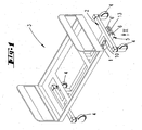
- FIG. 1 shows a perspective view of a hospital bed 3 with a chassis 2 and an additional roller 1 arranged thereon, but an accumulator and various controls have not been shown.
- the additional role 1 can be arranged between the rollers 4 of the head or foot of the hospital bed 3. But it is also conceivable that the additional roller 1 is fixed centrally to the four respectively arranged at the corners of the chassis 2 rollers 4 on the chassis 2.
- the additional roller 1 is in each case preferably oriented such that the running direction of the auxiliary roller 1 runs parallel to the longitudinal extent of the hospital bed 3.
- the additional roll 1 is received in a frame 5, which consists in the embodiment of two mutually parallel frame walls 6, 6 '. Between the frame walls 6, 6 ', the auxiliary roller 1 is arranged. Like in the FIG. 2 can be clearly seen, the additional role 1 off-center, namely closer to the frame wall 6 'arranged. This is a favorable nesting achieved with the other units still described.
- the direction of the additional roller 1 is parallel to the frame walls 6, 6 '.
- the shaft 7 of the auxiliary roller 1 is stored in stock by the frame wall 6 without passing through them, and passes through the frame wall 6 ', wherein here also a storage is realized.
- the shaft 7 is fixedly connected to the auxiliary roller 1.
- the protruding from the frame wall 6 'end of the shaft 7 is connected to a gear 8, via which gear 8, a drive motor 9, the auxiliary roller 1 drives.
- the transmission 8 and the drive motor 9 are fixed from the outside to the frame wall 6 '.
- the drive motor 9 is an electric motor.
- the transmission 8 is designed so that it is not self-locking and has the lowest possible internal friction. Hereby, a freewheel effect can be achieved.
- a plug connection 35 is provided on the transmission 8.
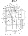
- a mounting plate 10 is provided.
- the mounting plate 10 between the frame walls 6, 6 ', whose the underside of the chassis of the hospital bed associated areas arranged.
- the frame 5 is pivotally connected by means of an axis 11 with the mounting plate 10 fixed in the installed state with the chassis of the hospital bed.
- the axis 11 is in the embodiment with the frame walls 6, 6 'screw-connected.
- the frame walls 6, 6 ' are connected not only by the axis 11 but also by the shaft 7 of the auxiliary roller 1.
- the frame 5 is also formed with cross connections 12, 13.
- a cross connection 12 is arranged in the vicinity of the auxiliary roller 1 and a further cross connection 13 in the form of an auxiliary sheet in the vicinity of the axis 11.
- the cross connection 12 is formed by a bolt which has a diameter-reduced portion 14.
- the bolt thus forms as it were a bracing between the frame walls 6, 6 '.
- the section 14 is assigned to the additional role 1.
- the cross-connection 13 is connected in the embodiment with the end faces of the frame walls 6,6 'by means of screws.
- holes 15 are formed in the mounting plate, which - are penetrated - in the embodiment - cylinder head bolts 16.
- the cylinder head bolts 16 are screw-retained in corresponding threaded bores 17 of the chassis 2.
- FIGS. 4 and 6 show a section through a bore 15 with inlaid cylinder head screw 16.
- the mounting plate 10 forms an open-edged recess 36 in the direction of the axis 11.
- the mounting plate 10 tapers in the region of the open-edged recess 36 and thus forms a sloping ceiling 37.
- This ceiling 37 projects beyond only a portion of the recess 36.
- the angle of the ceiling 37 is approximately 20 ° to the lying surface of the hospital bed 3.
- the recess 36 is arranged centrally in the mounting plate 10 and is about half as wide as the total width of the mounting plate 10 is (see FIG. 2 ).
- an end portion 38 of a support arm 18 is inserted in the recess 36.
- the end portion 38 is conformed to the width of the recess 36.
- the substantial width of the support arm 18 is wider than the width of the recess 36 and so the support arm 18 forms lateral shoulders 39 which rest on the mounting plate 10.
- the support arm 18 is fixedly connected to the mounting plate 10 by the axle 11.
- the shoulders 39 contribute to the fact that the support arm 18 is rigidly connected to the mounting plate 10.
- the support arm 18 has approximately a right angle to the mounting plate 10 and projects into the space between the two frame walls 6,6 '.
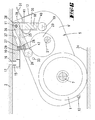
- an annular body 19 is arranged, which is rotatable according to the outer ring of a ball bearing on balls. Specifically, this is a storage of the balls and the ring body 19 receiving axis between two legs 40 is provided.
- an eccentric 20 cooperates with the annular body 19.
- the annular body 19 allows a rolling with respect to the eccentric 20.
- the eccentric 20 is, in the embodiment centered, between the frame walls 6,6 'arranged on a shaft 21.
- the shaft end which is associated with the frame wall 6, is part of a transmission 22.
- the shaft 21 can be driven by the pivoting drive 23.
- the pivot drive 23 and the gear 22 are mounted on the inside of the frame wall 6 and together form the pivot unit for the auxiliary roller 1.
- the pivot drive 23 is connected via a cable 24 with a power source, by means of an intermediate control device connected.
- the pivot drive 23 extends laterally along the auxiliary roller 1. The arrangement in a juxtaposition of the auxiliary roller 1 and the pivot drive 23 can be a favorable size of the frame 5 can be achieved.
- the two axes of symmetry of the pivoting drive 23 and the drive motor 9 are approximately parallel to each other.
- the symmetry axes of the shafts 7, 21 of the additional roller 1 and the eccentric 20 extend approximately at right angles to one another (see FIG. 2).
- a pressure lever 25 is provided.
- the pressure lever 25 is located directly in the pivoting path of the eccentric 20 or in the narrower sense of the shaft 21 when the frame 5 is pivoted.
- The is supported by a spring 27 which on the one hand rests against the chassis of the hospital bed or specifically in the embodiment of the mounting plate 10 and on the other hand - by means of the pressure lever 25 - on the eccentric 20.
- the pressure lever 25 is the embodiment further supported on the support arm 18.
- the support arm 18, on the chassis side, a recess 41, and an axis 11 which passes through the pressure lever 25 at the foot.
- the pressure lever 25 also has an annular body 26 on the eccentric side. Accordingly, the annular body 26 is supported by balls, not shown, corresponding to a ball bearing on the end of the pressure lever 25.
- the pressure lever 25 is urged by the spring 27 in a counterclockwise direction with respect to FIGS. 4 and 6 , charged. It is obvious that the pressure lever 25 thus always bears against the eccentric 20, while this need not be necessary for the support arm 18, cf. FIG. 6 , In this respect, the pressure lever 25 acts together with the spring 27 in the sense of a shock absorber. The movement of the auxiliary roller 1 on the ground, ie in the lowered position, can thereby be compensated and damped (relative to movements in the vertical direction).
- one end of the compression spring 27 is received in a receiving cavity 28 of the pressure lever 25.
- the other end of the spring 27 is located in a receiving cavity 29 of the ceiling 37 of the recess 36 of the mounting plate 10 a.
- a sensor 30 is arranged laterally on the support arm 18.
- the sensor 30 may be, for example, an inductive proximity switch.
- a necessary for the sensor 30 connecting cable 31 is mounted on the side of the auxiliary roller 1 of the sensor 30. This connection cable 31 is subsequently passed through a bore 32, which runs parallel to the mounting plate 10.
- the sensor 30 is arranged at the height of the cross connection 13 (see FIGS. 4 and 6 ).
- the shafts 7,21 are received by ball bearings, which have not been shown in the drawings.
- the ball bearings lie in receiving holes in the frame walls 6,6 'of the frame 5 a.
- the additional role 1 in the release position.
- the additional role 1 is limited in the direction of the release position by the stopper pin 33, which abuts against the mounting plate 10.
- the auxiliary roller 1 is spaced from the floor 34.
- the drive direction of the auxiliary roller 1 can be selected by a directional switch, and then the auxiliary roller 1 can be moved into its ground contact position by a push-button (FIG. FIG. 6 ) are relocated.
- the button By pressing the button, the pivoting drive 23 is started, so that the eccentric 20 from the position in FIG. 4 in the position in FIG. 6 relocated.
- FIG. 4 (Release position) is the range of the largest dimension (the distance of the outer periphery of the eccentric disc to the axial center of the eccentric axis) of the eccentric 20 to the annular body 19 of the support arm 18 at.
- the annular body 26 of the pressure lever 25 abuts the eccentric 20 and has a much smaller distance to the axis of symmetry of the shaft 21 than the annular body 19, in a peripheral region which is near or at the smallest distance to the eccentric axis.
- the FIG. 5 shows an intermediate position.
- the eccentric 20 was displaced by means of the pivoting drive 23 in the counterclockwise direction.
- the region of the largest dimension of the eccentric 20 bears against the annular body 26 of the pressure lever 25.
- the shaft 21 has a much smaller distance to the annular body 19, wherein the eccentric 20 and the annular body 19 is preferred do not touch.
- the eccentric 20 has a certain distance from the annular body 19 of the support arm 18.
- a "springing" of the auxiliary roll 1 is achieved, that when unevenness in the floor 34 occur, the spring 27, the additional roll 1 can shift further counterclockwise, so that there is always a ground contact of the auxiliary roll 1.
- the spring 27 compensates for the unevenness in the floor 34.
- the additional drive falls away by the drive motor 9 and the pivot drive moves the eccentric 20 in the position that in the FIG. 4 has been shown.
- the eccentric 20 runs on the annular body 19 and increases the distance between the axis of the annular body 19 and the axis of the shaft 21.
- the frame 5 is pivoted about the axis 11 in the direction of the release position.
Landscapes
- Engineering & Computer Science (AREA)
- Chemical & Material Sciences (AREA)
- Combustion & Propulsion (AREA)
- Transportation (AREA)
- Mechanical Engineering (AREA)
- Health & Medical Sciences (AREA)
- Nursing (AREA)
- Life Sciences & Earth Sciences (AREA)
- Animal Behavior & Ethology (AREA)
- General Health & Medical Sciences (AREA)
- Public Health (AREA)
- Veterinary Medicine (AREA)
- Invalid Beds And Related Equipment (AREA)
Description
- Die Erfindung betrifft ein Krankenhausbett mit einem Chassis, mit vier an dem Chassis angebrachten Laufrollen und mindestens einer weiteren in Bodenkontakt bringbaren wahlweise antreibbaren Zusatzrolle, wobei die Zusatzrolle an einem starren Rahmen gelagert ist und zusammen mit dem Rahmen relativ zu dem Chassis durch Verschwenken anhebbar oder absenkbar ist, wobei weiter ein an dem Rahmen befestigter Antriebsmotor für die Zusatzrolle vorgesehen ist und ein gesonderter Verschwenkantrieb zum Anheben und Absenken der Zusatzrolle vorgesehen ist.
- Aus der
CA 2457182 A1 ist ein gattungsgemäßes Krankenhausbett vorbekannt. Die Zusatzrolle ist in einem Gehäuse aufgenommen, welches Gehäuse schwenkbeweglich mit dem Chassis verbunden ist. Am freien Ende des Gehäuses greift ein gesonderter Verschwenkantrieb an, welcher schwenkbeweglich mit dem Chassis verbunden ist. - Des Weiteren ist aus der
US 6772850 B1 ein gattungsgemäßes Krankenhausbett vorbekannt. Die Zusatzrolle und der Antriebsmotor sind von einem Gehäuse aufgenommen, welches an einem Ende einer Blattfeder montiert ist. Das andere Ende der Blattfeder ist mit dem Chassis verbunden. Die Blattfeder beaufschlagt die Zusatzrolle in Richtung des Fußbodens. Um die Zusatzrolle von dem Fußboden zu beabstanden, ist ein Mechanismus vorgesehen, der an einem dem Gehäuse überstehenden Ende der Blattfeder angreift und diese spannt. Der Mechanismus ist fest mit dem Chassis verbunden. Gibt der Mechanismus die Blattfeder frei, so verlagert sich die Zusatzrolle in Richtung des Fußbodens. - Darüber hinaus ist zu entsprechenden Krankenhausbetten auch auf die
CA 2010543 A ,DE 10120316 C1 ,FR 2735019 A1 US 5083625 A ,US 6725956 B1 ,US 6752224 B2 undWO 01 / 19313 A1 US 5135063 A ist eine motorisch antreibbare Zusatzrolle für einen Rollstuhl bekannt. - Der Erfindung liegt die Aufgabe zugrunde, ein gattungsgemäßes Krankenhausbett wie eingangs vorausgesetzt, vorteilhaft auszugestalten.
- Diese Aufgabe ist bei einem Krankenhausbett mit den Merkmalen des Anspruchs 1 gelöst, wobei darauf abgestellt ist, dass der gesonderte Verschwenkantrieb insgesamt an dem Rahmen befestigt ist und mit diesem verschwenkt.
- Zufolge einer derartigen Ausgestaltung bilden der Verschwenkantrieb, die Zusatzrolle und der Antriebsmotor zusammen mit dem Rahmen eine Einheit. Der Rahmen nimmt dadurch auch vollständig das Gewicht des Verschwenkantriebes auf. Grundsätzlich ist nur noch ein Verschwenkgelenk, bezüglich des Rahmens, relativ zu dem Chassis, erforderlich. Die Einheit kann als Ganzes an einem Chassis eines Krankenhausbettes in einfachster Weise montiert werden. Dies ermöglicht es, im Rahmen einer werkstattmäßigen Vormontage, bereits die Ausrichtung des Schwenkantriebes, speziell eines Exzenters, wie nachstehend noch im Einzelnen beschrieben, im Hinblick auf die Zusatzrolle vorzunehmen. Die Einheit aus Rahmen, Antriebsmotor und Zusatzrolle ist auch vorteilhaft im Hinblick auf eine Ertüchtigung vorhandener Krankenhausbetten mit einer solchen Zusatzrolle. Unabhängig oder ergänzend hierzu ist die kompakte Bauweise von Vorteil. Im weiteren auch der Umstand, dass gewichtsmäßig eine Konzentration geschaffen ist. Dies kann zur Stabilität des Krankenhausbettes noch beitragen.
- Es erweist sich als vorteilhaft, dass der Verschwenkantrieb mittels eines Exzenters den Rahmen relativ zu dem Chassis, an dem der Exzenter auch abgestützt ist, bewegt. Es ist nur eine berührende Zusammenwirkung insoweit mit dem Chassis erforderlich, aber beispielsweise keine gelenkartige Verbindung. Diese kann, wie noch erläutert, vielmehr unabhängig hiervon realisiert sein. Zudem sind vorteilhaft die beweglichen Teile reduziert. Der Exzenter kann durch eine auf die Welle fest aufgebrachte Exzenterscheibe gebildet sein. Die Drehbewegung für den Exzenter wird von dem Verschwenkantrieb erzeugt. Wenn die Anordnung so vorgesehen ist, dass die Achsen des Verschwenkantriebes und des Exzenters sich kreuzen, ist ein Getriebe erforderlich um die Antriebskraft von dem Verschwenkantrieb auf den Exzenter zu übertragen. Bevorzugt ist jedoch, dass die Achsen bzw. Wellen insoweit parallel sind oder fluchten. Eine Antriebswelle des Verschwenkantriebs kann hierzu vorteilhafterweise unmittelbar die bereits angesprochene Exzenterscheibe tragen.
- Soweit bzw. solange der Exzenter sich an dem Chassis abstützt, ist auch ein Anschlag (ständig) gegeben in Bezug auf eine Bodenkontaktstellung der Zusatzrolle. Insoweit ist eine vergleichbar starre (in Druckrichtung der Zusatzrolle) Zusammenwirkung zwischen der Zusatzrolle und dem Chassis gegeben ist wie es bezüglich der herkömmlichen Rollen bei einem solchen Krankenhausbett ohnehin der Fall ist. Andererseits kann die - ledigliche - Exzenterabstützung der Zusatzrolle am Chassis des Krankenhausbettes auch dahingehend genutzt sein, dass der Exzenter in der Bodenkontaktstellung nicht unmittelbar an dem Chassis anliegt, sondern unter Vermittlung eines Ausgleichsteiles. Ein solches Ausgleichsteil kann weiter bevorzugt ein Federteil sein, das sich entsprechend einerseits an dem Chassis und andererseits an der Zusatzrolle bzw. speziell dem Exzenter abstützt. Geeignet ist insofern eine den Rahmen (insgesamt) in die abgesenkte Stellung vorspannende Druckfeder. Diese Druckfeder wirkt dann bei abgesenkter, in Bodenkontakt befindlicher Zusatzrolle wie ein Stoßdämpfer.
- Der Kontakt der Zusatzrolle mit dem Fußboden ist auch bei schneller Fahrt und Unebenheiten gesichert.
- Zugleich werden entsprechende Unebenheiten im Fußboden durch die Feder ausgeglichen, ohne dass es etwa einer Verstellung des Exzenters oder eines Ausgleichs durch ein Getriebe bedarf.
- Weiter bevorzugt ist vorgesehen, dass die genannte Druckfeder vermittels eines an einer chassisfesten Achse angelegten Druckhebels auf den Exzenter einwirkt. Der Druckhebel kann um dieselbe Achse wie auch die Zusatzrolle verschwenken. Dies ist in der Regel auch dieselbe Achse, welche den Rahmen an dem Chassis verschwenkbar haltert.
- Mittels des Druckhebels kann die unmittelbare Zusammenwirkung mit dem Exzenter realisiert sein. Es ist nicht erforderlich, dass die Feder unmittelbar an dem Exzenter anliegt. Um im Weiteren die Beanspruchungen hinsichtlich der erforderlichen Relativbewegungen zwischen dem Druckhebel und dem Exzenter günstig zu gestalten, kann eine Rolle, beispielsweise nach Art eines Kugellagerrings, an dem Druckhebel oder gegebenenfalls auch an dem Exzenter vorgesehen sein. Es ergibt sich so bei Bewegung eine günstige Rollenübertragung.
- Der Exzenter wirkt aber nicht nur über die Feder mit dem Chassis zusammen. Denn allein hierdurch wäre der Rahmen ständig in der abgesenkten Stellung. Zur Anhebung und Absenkung ist vielmehr zusätzlich, zumindest bezüglich eines gewissen Teilbereichs des Absenk- oder Anhebehubes, eine starre Abstützung des Exzenters relativ zu dem Chassis erforderlich. Hierzu ist ein Stützarm vorgesehen, mit welchem - umfangsmäßig in Bezug auf den Exzenter versetzt zu der Zusammenwirkung zwischen dem beschriebenen Druckhebel und dem Exzenter (wenn der Druckhebel vorgesehen ist) - der Exzenter ebenfalls zusammenwirkt. Auch hinsichtlich dieses Stützarms empfiehlt sich die Realisierung einer Rollbewegung, durch die bereits im Zusammenhang mit dem Druckhebel beschriebene kugellagerartige Ausbildung.
- Der Stützarm bildet den bereits angesprochenen Anschlag für den Exzenter aus.
- Im Weiteren ist bevorzugt auch eine Montageplatte vorgesehen, mit welcher der Rahmen schwenkbeweglich verbunden ist, wobei - erst - die Montageplatte fest mit dem Chassis des Krankenhausbettes verbunden ist. Bevorzugt ist auch der erwähnte Stützarm Teil der Montageplatte. Die Anlenkung (Schwenklager) bzw. Abstützung des Exzenters, gegebenenfalls auch vermittels der beschriebenen Druckfeder, findet somit nur relativ zu einem Teil statt, das ohne Weiteres in die Baugruppe des Rahmens mit Zusatzrolle und Verschwenkantrieb einbezogen sein kann. Die Montageplatte allein ist fest an dem Chassis zu montieren. Der Rahmen ist - nur - schwenkbeweglich mit der Montageplatte verbunden.
- Entsprechend wird die Aufrüstung eines Krankenhausbettes mit der Zusatzrolle durch die Montageplatte nochmals entscheidend vereinfacht. Es müssen an dem Chassis des Krankenhausbettes beispielsweise nur die Bohrungen zur Befestigung der Montageplatte hergestellt werden.
- Hinsichtlich des Rahmens selbst ist bevorzugt vorgesehen, dass er aus zwei gegenüberliegenden Rahmenwänden besteht, in deren Längserstreckung hintereinander die Wellen der Zusatzrolle und des Exzenters gelagert sind. Weiter kann vorgesehen sein, dass die Rahmenwände, zusätzlich zu der Verbindung durch die genannten Wellen, noch mittels einer nur der Versteifung dienenden Querverbindung miteinander verbunden sind. Zwischen den Rahmenwänden sind die Zusatzrolle, der Exzenter, der Verschwenkantrieb, der Druckhebel mit Feder und der Stützarm aufgenommen. Durch die Rahmenwände sind diese Bauteile vor äußeren Einwirkungen günstig geschützt.
- Eine zusätzliche Querverbindung, wie angesprochen, ist bevorzugt dahingehend vorgesehen, dass sie zur Erlangung eines Messwertes dient, der ermitteln lässt, in welcher (Absenk-) Position sich die Zusatzrolle befindet. Hierzu kann beispielsweise ein induktiver Näherungsschalter an dem Stützarm vorgesehen sein, der die Entfernung von dieser Verstrebung zu dem Stützarm registriert. Der Stützarm ist feststehend, während die Querverbindung sich zusammen mit dem Rahmen bei einer Absenkung oder Anhebung bewegt. Die Querverbindung kann zu diesem Zweck beispielsweise aus einem einfachen Blechstreifen bestehen, da die Aufnahme von Kräften nicht im Vordergrund steht.
- Auch der Verschwenkantrieb für den Exzenter ist bevorzugt vollständig zwischen den Rahmenwänden angeordnet. Dagegen kann ein Antriebsmotor und/oder ein Getriebe für die Zusatzrolle außenseitig an einer der Rahmenwände angeordnet sein. Hier ist es in der Abwägung günstig, wenn der Antriebsmotor ohne Weiteres zugänglich ist. Da im Weiteren ohnehin der Antriebsmotor für die Zusatzrolle wesentlich größer ist als etwa der Antriebsmotor für den Verschwenkantrieb, würde ansonsten erheblicher Leerraum zwischen den Rahmenwänden sich ergeben.
- Die Zusatzrolle kann eine Bockrolle sein, deren Lauffläche vergleichbar weich ausgestaltet ist (zum Beispiel aus Weichgummi, um eine gute Traktion zu erreichen). Der Durchmesser der Zusatzrolle ist bevorzugt gleich oder kleiner als der Durchmesser der weiteren, üblichen, am Chassis des Krankenhausbettes angebrachten Laufrollen. Das vorzugsweise zwischen dem Antriebsmotor für die Zusatzrolle und die Zusatzrolle geschaltete Getriebe ist weiter bevorzugt so ausgebildet, dass es keine Selbsthemmung besitzt, also nur einen möglichst niedrigen Reibungswert. Dies ist vorteilhaft dahingehend, dass auch bei Ausfall des Motors oder etwa wenn der Motor für kleinere Strecken nicht eingeschaltet werden soll, ein einfaches Verschieben des Krankenhausbettes auch bei abgesenkter Zusatzrolle günstig möglich ist. Die Zusatzrolle weist in diesem Sinne einen Freilauf auf.
- Zur Versorgung des Antriebsmotors und des Verschwenkantriebes mit elektrischen Strom ist bevorzugt vorgesehen, dass eine entsprechende Verbindung mit einem in der Regel schon vorhandenen Akkumulator in dem Krankenhaus-, bett vorgenommen wird. Etwa zur Verstellung von Kopf- und/oder Fußteilen des Bettes sind in der Regel bereits Elektroantriebe an dem Krankenhausbett vorhanden, die über einen Akkumulator versorgt werden können. Zur Steuerung, das heißt insbesondere Aktivierung und Deaktivierung der Zusatzrolle bzw. zum Absenken und Hochfahren der Zusatzrolle, sind entsprechende Schalter und eine Steuereinheit am Krankenhausbett dann bevorzugt vorgesehen. Der Schalter kann ein Drucktaster sein, welcher die gesamte Zeit betätigt werden muss, wenn die Unterstützung der Zusatzrolle genutzt werden soll. Dies bringt den Vorteil der sicheren Betätigung mit sich. Auf die Betätigung der Drucktaste hin kann zum Einen die Zusatzrolle mit Hilfe des Verschwenkantriebes aus der Freigabestellung in die Bodenkontaktstellung verschwenken und zum Anderen der Antriebsmotor die Zusatzrolle antreiben.
- Dieser beschriebene Ablauf kann beispielsweise in einer Steuerung des Steuergerätes niedergelegt sein. Weiter, insbesondere ergänzend, ist es auch bevorzugt, mit Hilfe des Steuergerätes die Zusatzrolle antriebsmäßig so zu steuern, dass eine langsame Beschleunigung realisiert ist. Hierdurch soll ein ruckfreies Anfahren des Krankenhausbettes möglich sein. In weiterer bevorzugter Ausgestaltung der Steuerung ist auch vorgesehen, dass der Antriebsmotor der Zusatzrolle eigenständig abschaltet, wenn der verbleibende Energieinhalt des Akkumulators ein gewisses, vorgegebenes Maß unterschreitet. Dies insbesondere auch um sicherzustellen, dass die verbleibende Energie ausreicht, die Zusatzrolle mittels des Verschwenkantriebes in die Freigabestellung zu verlagern. Zur Abfrage der Position der Zusatzrolle kann ein entsprechender Abfragemechanismus vorgesehen sein. Geeignet ist beispielsweise ein induktiver Näherungsschalter, welcher die Position der Zusatzrolle relativ zu dem Chassis des Krankenhausbettes erfasst. In konkreterer Ausgestaltung kann hierzu vorgesehen sein, dass ein solcher Näherungsschalter an dem Stützarm angebracht ist, der von der Unterseite des Chassis des Krankenhausbettes zwischen die Rahmenwände ragt. Wenn sich nun der Rahmen absenkt, kann der Näherungsschalter, der am Stützarm angebracht ist, ein mit dem Rahmen verschwenkendes Teil hinsichtlich der Entfernung zum Näherungsschalter erfassen und hieraus die Stellung der Zusatzrolle ableiten.
- Die Erfindung wird nachstehend anhand der beigefügten Zeichnung, die jedoch lediglich ein Ausführungsbeispiel darstellt, näher erläutert. Hierbei zeigt:
- Fig. 1
- eine perspektivische Ansicht eines Krankenhausbettes, an dessen Chassis eine Zusatzrolle montiert ist, die sich in der Freigabestellung befindet;
- Fig. 2
- eine Unteransicht der Zusatzrolle in Blickrichtung II aus
Fig. 1 ; - Fig. 3
- eine perspektivische Unteransicht der Zusatzrolle;
- Fig. 4
- einen Schnitt entlang der Linie IV - IV aus
Fig. 2 ; - Fig. 5
- eine Seitenansicht der Zusatzrolle in der Zwischenstellung gemäß Blickrichtung V aus
Fig. 2 und - Fig. 6
- einen Schnitt entsprechend
Fig. 4 , jedoch befindet sich hier die Zusatzrolle in der Bodenkontaktstellung. - Die
Figur 1 zeigt eine perspektivische Ansicht eines Krankenhausbettes 3 mit einem Chassis 2 und einer daran angeordneten Zusatzrolle 1, wobei jedoch ein Akkumulator und verschiedene Bedienelemente nicht dargestellt worden sind. Die Zusatzrolle 1 kann zwischen den Laufrollen 4 des Kopf- oder Fußendes des Krankenhausbettes 3 angeordnet sein. Es ist aber auch denkbar, dass die Zusatzrolle 1 zentrisch zu den vier jeweils an den Ecken des Chassis 2 angeordneten Laufrollen 4 an dem Chassis 2 fixiert ist. Die Zusatzrolle 1 ist jeweils bevorzugt so ausgerichtet, dass die Laufrichtung der Zusatzrolle 1 parallel zu der Längserstreckung des Krankenhausbettes 3 verläuft. - Die Zusatzrolle 1 ist in einem Rahmen 5 aufgenommen, welcher beim Ausführungsbeispiel aus zwei parallel zueinander angeordneten Rahmenwänden 6, 6' besteht. Zwischen den Rahmenwänden 6, 6' ist die Zusatzrolle 1 angeordnet. Wie in der
Figur 2 gut zu erkennen ist, ist die Zusatzrolle 1 außermittig, nämlich näher an der Rahmenwand 6' angeordnet. Damit ist eine günstige Einschachtelung mit den weiteren noch beschriebenen Aggregaten erreicht. Die Laufrichtung der Zusatzrolle 1 ist parallel zu den Rahmenwänden 6, 6'. Die Welle 7 der Zusatzrolle 1 ist lagernd von der Rahmenwand 6 aufgenommen, ohne diese zu durchsetzen, und durchragt die Rahmenwand 6', wobei hier auch eine Lagerung realisiert ist. Die Welle 7 ist fest mit der Zusatzrolle 1 verbunden. Das aus der Rahmenwand 6' herausragende Ende der Welle 7 ist mit einem Getriebe 8 verbunden, über welches Getriebe 8 ein Antriebsmotor 9 die Zusatzrolle 1 antreibt. Das Getriebe 8 sowie der Antriebsmotor 9 sind von außen an der Rahmenwand 6' befestigt. Der Antriebsmotor 9 ist ein Elektromotor. Das Getriebe 8 ist so ausgebildet, dass es nicht selbsthemmend ist und eine möglichst geringe innere Reibung aufweist. Hiermit kann eine Freilaufwirkung erzielt werden. Zur Stromversorgung des Antriebsmotors 9 ist an dem Getriebe 8 ein Steckanschluss 35 vorgesehen. - Zusätzlich zu den Rahmenwänden 6, 6' ist eine Montageplatte 10 vorgesehen. Beim Ausführungsbeispiel ist die Montageplatte 10 zwischen den Rahmenwänden 6, 6', deren der Unterseite des Chassis des Krankenhausbettes zugeordneten Bereichen, angeordnet. Der Rahmen 5 ist mittels einer Achse 11 schwenkbeweglich mit der im Einbauzustand fest mit dem Chassis des Krankenhausbettes verbundenen Montageplatte 10 verbunden. Die Achse 11 ist beim Ausführungsbeispiel mit den Rahmenwänden 6, 6' schraubverbunden. Die Rahmenwände 6, 6' sind nicht nur durch die Achse 11, sondern auch durch die Welle 7 der Zusatzrolle 1 verbunden. Der Rahmen 5 ist darüber hinaus mit Querverbindungen 12, 13 ausgebildet. Eine Querverbindung 12 ist in der Nähe der Zusatzrolle 1 und eine weitere Querverbindung 13 in Form eines Hilfsbleches in der Nähe der Achse 11 angeordnet. Die Querverbindung 12 wird durch einen Bolzen gebildet, welcher einen durchmesserverringerten Abschnitt 14 aufweist. Der Bolzen bildet also gleichsam eine Verstrebung aus zwischen dem Rahmenwänden 6, 6'. Der Abschnitt 14 ist der Zusatzrolle 1 zugeordnet. Die Querverbindung 13 ist beim Ausführungsbeispiel mit den Stirnflächen der Rahmenwände 6,6' mittels Schrauben verbunden.
- Zur festen Verbindung der Montageplatte 10 mit dem Chassis 2 des Krankenhausbettes 3 sind in der Montageplatte 10 Bohrungen 15 ausgebildet, welche von - beim Ausführungsbeispiel - Zylinderkopfschrauben 16 durchsetzt sind. Die Zylinderkopfschrauben 16 sind in entsprechenden Gewindebohrungen 17 des Chassis 2 schraubgehaltert.
- Die
Figuren 4 und6 zeigen einen Schnitt durch eine Bohrung 15 mit einliegender Zylinderkopfschraube 16. Wie aus denFiguren 2 und4 besonders hervorgeht, bildet die Montageplatte 10 eine randoffene Aussparung 36 in Richtung der Achse 11 aus. Die Montageplatte 10 verjüngt sich im Bereich der randoffenen Aussparung 36 und bildet so eine schräg verlaufende Decke 37 aus. Diese Decke 37 überragt nur einen Teil der Aussparung 36. Im Endbereich geht die Aussparung 36 komplett durch die Montageplatte 10 hindurch. Der Winkel der Decke 37 beträgt in etwa 20° zur Liegefläche des Krankenhausbettes 3. Die Aussparung 36 ist zentrisch in der Montageplatte 10 angeordnet und ist etwa halb so breit, wie die Gesamtbreite der Montageplatte 10 beträgt (sieheFigur 2 ). - In der Aussparung 36 steckt ein Endabschnitt 38 eines Stützarmes 18 ein. Der Endabschnitt 38 ist der Breite der Aussparung 36 formangepasst. Die wesentliche Breite des Stützarmes 18 ist breiter als die Breite der Aussparung 36 und so bildet der Stützarm 18 seitliche Schultern 39 aus, die auf der Montageplatte 10 aufliegen. Der Stützarm 18 wird durch die Achse 11 fest mit der Montageplatte 10 verbunden. Die Schultern 39 tragen dazu bei, dass der Stützarm 18 starr an die Montageplatte 10 angebunden ist. Der Stützarm 18 weist etwa einen rechten Winkel zu der Montageplatte 10 auf und ragt in den Zwischenraum zwischen den beiden Rahmenwänden 6,6'. Am freien Ende des Stützarmes 18 ist ein Ringkörper 19 angeordnet, welcher entsprechend dem Außenring eines Kugellagers auf Kugeln drehbar ist. Im Einzelnen ist hierzu eine Lagerung der die Kugeln und den Ringkörper 19 aufnehmenden Achse zwischen zwei Schenkeln 40 vorgesehen.
- Wie insbesondere
Figur 2 zu entnehmen ist, wirkt ein Exzenter 20 mit dem Ringkörper 19 zusammen. Der Ringkörper 19 ermöglicht ein Abrollen bezüglich des Exzenters 20. Der Exzenter 20 ist, beim Ausführungsbeispiel mittig, zwischen den Rahmenwänden 6,6' auf einer Welle 21 angeordnet. - In der
Figur 2 ist weiter zu erkennen, dass das Wellenende, welches der Rahmenwand 6 zugeordnet ist, Teil eines Getriebes 22 ist. Vermittels des Getriebes 22 kann die Welle 21 durch den Verschwenkantrieb 23 angetrieben werden. Der Verschwenkantrieb 23 sowie das Getriebe 22 sind auf der Innenseite der Rahmenwand 6 befestigt und bilden zusammen die Verschwenkeinheit für die Zusatzrolle 1. Der Verschwenkantrieb 23 ist über ein Kabel 24 mit einer Stromquelle, vermittels auch eines zwischengeschalteten Steuergerätes, verbunden. Wie darüber hinausFigur 2 zu entnehmen ist, verläuft der Verschwenkantrieb 23 seitlich entlang der Zusatzrolle 1. Durch die Anordnung in einer Nebeneinanderbeziehung der Zusatzrolle 1 und des Verschwenkantriebes 23 lässt sich eine günstige Baugröße des Rahmens 5 erzielen. - Wie den
Figuren 2 und5 weiter zu entnehmen ist, verlaufen die beiden Symmetrieachsen des Verschwenkantriebes 23 und des Antriebsmotors 9 etwa parallel zueinander. Die Symmetrieachsen der Wellen 7,21 von der Zusatzrolle 1 und dem Exzenter 20 verlaufen etwa im rechten Winkel zueinander (siehe Figur 2). - Zusätzlich zu dem Stützarm 18 ist ein Druckhebel 25 vorgesehen. Der Druckhebel 25 liegt unmittelbar in der Verschwenkbahn des Exzenters 20 bzw. im engeren Sinne der Welle 21, wenn der Rahmen 5 verschwenkt wird. Der um eine Achse 25 verschenkbare Druckhebel 11 ist durch eine Feder 27 abgestützt, welche einerseits an dem Chassis des Krankenhausbettes bzw. speziell beim Ausführungsbeispiel der Montageplatte 10 anliegt und andererseits - vermittels des Druckhebels 25 - an dem Exzenter 20. Der Druckhebel 25 ist beim Ausführungsbeispiel weiter an dem Stützarm 18 gelagert. Hierfür weist der Stützarm 18, chassisseitig, eine Aussparung 41 auf, und eine Achse 11, die den Druckhebel 25 fußseitig durchsetzt. Wie auch schon im Hinblick auf den Stützarm 18 erläutert, weist auch der Druckhebel 25 exzenterseitig einen Ringkörper 26 auf. Entsprechend wird auch der Ringkörper 26 von nicht dargestellten Kugeln entsprechend einem Kugellager auf dem Ende des Druckhebels 25 gelagert. In Einzelheit wiederum durch eine Achse zwischen zwei Schenkeln 42 des Druckhebels 25.
- Der Druckhebel 25 wird von der Feder 27 in eine Richtung entgegen dem Uhrzeigersinn, bezogen auf die
Figuren 4 und6 , beaufschlagt. Es ist ersichtlich, dass der Druckhebel 25 somit immer an dem Exzenter 20 anliegt, während dies für den Stützarm 18 nicht notwendig gegeben sein muss, vgl.Figur 6 . Insofern wirkt der Druckhebel 25 zusammen mit der Feder 27 im Sinne eines Stoßdämpfers. Die Bewegung der Zusatzrolle 1 auf dem Boden, also in der abgesenkten Stellung, kann hierdurch ausgeglichen und gedämpft werden (bezogen auf Bewegungen in Vertikalrichtung). - In weiterer Einzelheit ist ein Ende der Druckfeder 27 in einer Aufnahmehöhlung 28 des Druckhebels 25 aufgenommen. Das andere Ende der Feder 27 liegt in einer Aufnahmehöhlung 29 der Decke 37 der Aussparung 36 der Montageplatte 10 ein.
- Wie den
Figuren 2 und3 weiter zu entnehmen ist, ist seitlich an dem Stützarm 18 ein Sensor 30 angeordnet. Bei dem Sensor 30 kann es sich beispielsweise um einen induktiven Näherungsschalter handeln. Ein für den Sensor 30 notwendiges Anschlusskabel 31 ist auf der Seite der Zusatzrolle 1 des Sensors 30 angebracht. Dieses Anschlusskabel 31 ist im Weiteren durch eine Bohrung 32, welche parallel zu der Montageplatte 10 verläuft, hindurchgeführt. Der Sensor 30 ist auf der Höhe der Querverbindung 13 angeordnet (sieheFiguren 4 und6 ). - Wie ebenfalls in den
Figuren 2 und3 gut zu erkennen ist, ragt ein Anschlagstift 33 ausgehend von der Rahmenwand 6' in den Zwischenraum zwischen den beiden Rahmenwänden 6, 6'. In derFigur 4 ist gut zu erkennen, dass der Anschlagstift 33 ein zu weites Verschwenken des Rahmens 5 im Uhrzeigersinn verhindert. Der Anschlagstift 33 stößt in der Freigabestellung mit seiner Mantelfläche an der Oberfläche der Montageplatte 10 an und begrenzt so den Verschwenkweg des Rahmens 5. - Bevorzugt werden die Wellen 7,21 von Kugellagern aufgenommen, die in den Zeichnungen nicht dargestellt worden sind. Die Kugellager liegen dabei in Aufnahmebohrungen in den Rahmenwänden 6,6' des Rahmens 5 ein.
- Nachfolgend wird die Wirkungsweise der erfindungsgemäßen Zusatzrolle 1 näher beschrieben:
- In den
Figuren 1 bis 4 befindet sich die Zusatzrolle 1 in der Freigabestellung. Die Zusatzrolle 1 wird in Richtung der Freigabestellung durch den Anschlagstift 33 begrenzt, welcher gegen die Montageplatte 10 stößt. Die Zusatzrolle 1 ist von dem Fußboden 34 beabstandet. - Wird nun die Unterstützung der Zusatzrolle 1 benötigt, kann durch einen Richtungsschalter die Antriebsrichtung der Zusatzrolle 1 gewählt werden, und anschließend kann durch einen Drucktaster die Zusatzrolle 1 in ihre Bodenkontaktstellung (
Figur 6 ) verlagert werden. Durch Betätigen des Tasters wird der Verschwenkantrieb 23 gestartet, so dass sich der Exzenter 20 von der Stellung inFigur 4 in die Stellung inFigur 6 verlagert. In derFigur 4 (Freigabestellung) liegt der Bereich der größten Abmessung (der Abstand des Außenumfangs der Exzenterscheibe zum Achsmittelpunkt der Exzenterachse) des Exzenters 20 an dem Ringkörper 19 des Stützarms 18 an. Der Ringkörper 26 des Druckhebels 25 liegt an dem Exzenter 20 an und weist dabei einen wesentlich geringeren Abstand zu der Symmetrieachse der Welle 21 auf als der Ringkörper 19, und zwar in einem Umfangsbereich der nahe des oder am geringsten Abstand zu der Exzenterachse sich befindet. DieFigur 5 zeigt eine Zwischenstellung. In derFigur 6 wurde der Exzenter 20 mittels des Verschwenkantriebes 23 gegen den Uhrzeigersinn verlagert. In dieser Position (Bodenkontaktstellung) liegt der Bereich der größten Abmessung des Exzenters 20 an dem Ringkörper 26 des Druckhebels 25 an. Nun weist die Welle 21 einen wesentlich geringeren Abstand zu dem Ringkörper 19 auf, wobei sich der Exzenter 20 und der Ringkörper 19 bevorzugt nicht berühren. Der da verbleibende - und auch dargestellte - Abstand zwischen dem Außenumfang des Exzenters 20 und dem Ringkörper 19 ermöglicht ein "Durchfedern" der Zusatzrolle 1 bei Unebenheiten im Fußboden. Dies wird weiter unten noch im Einzelnen erläutert. In der Bodenkontaktstellung ist die Feder 27 weiter komprimiert als in der Freigabestellung. Somit wird eine hohe Anpresskraft zwischen der Zusatzrolle 1 und dem Fußboden 34 erreicht. Die hohe Anpresskraft ermöglicht auch eine gute Traktion der Zusatzrolle 1 bei weniger griffigen Fußböden wie beispielsweise nach einer Reinigung. Durch die Feder 27 und den Druckhebel 25 wird der Rahmen 5 samt der Zusatzrolle 1 ausgehend von denFiguren 4 und6 um die Achse 11 entgegen des Uhrzeigersinns verlagert. In derFigur 6 wird die Zusatzrolle 1 von der Kraft der Feder 27 auf den Fußboden 34 gedrückt. In dieser Bodenkontaktstellung weist der Exzenter 20 einen gewissen Abstand zu dem Ringkörper 19 des Stützarms 18 auf. Dadurch wird ein "Durchfedern" der Zusatzrolle 1 erreicht, dass, wenn Unebenheiten im Fußboden 34 auftreten, die Feder 27 die Zusatzrolle 1 weiter entgegen des Uhrzeigersinns verlagern kann, so dass immer ein Bodenkontakt von der Zusatzrolle 1 gegeben ist. Die Feder 27 gleicht die Unebenheiten im Fußboden 34 aus. Nachdem die Zusatzrolle 1 in die Position gemäßFigur 6 verlagert worden ist, aktiviert das Steuergerät den Antriebsmotor 9 der Zusatzrolle 1, so dass dieser die Zusatzrolle 1 langsam anfahren lässt. Nun wird eine das Krankenhausbett 3 verfahrende Person so lange beim Verfahren von der Zusatzrolle 1 unterstützt, wie diese Person den Drucktaster betätigt. Wenn der Drucktaster freigegeben wird, fällt der zusätzliche Antrieb durch den Antriebsmotor 9 weg und der Verschwenkantrieb verlagert den Exzenter 20 in die Position, die in derFigur 4 dargestellt worden ist. Dabei läuft der Exzenter 20 auf dem Ringkörper 19 ab und vergrößert den Abstand zwischen der Achse des Ringkörpers 19 und der Achse der Welle 21. Der Rahmen 5 wird um die Achse 11 in Richtung der Freigabestellung verschwenkt. - Bevorzugt ist auch, dass nur solange die Unterstützung durch die Zusatzrolle 1 gegeben ist, bis ein vorgegebenes Energieniveau des Akkumulators erreicht ist. Wenn dieses Energieniveau erreicht ist, schaltet das Steuergerät den Antriebsmotor 9 für die Zusatzrolle 1 ab. Das Energieniveau reicht jedoch noch aus, um die Zusatzrolle 1 wieder mittels des Verschwenkantriebes 23 in ihre Freigabestellung zu verlagern. So bleiben wichtige Funktionen des Krankenhausbettes 3 erhalten.
- Wie in den
Figuren 4 und6 zu sehen ist, entstehen bei den unterschiedlichen Stellungen der Zusatzrolle 1 auch unterschiedliche Abstände zwischen der Querverbindung 13 und dem Stützarm 18, an welchem auch der Sensor 30 angeordnet ist. Durch die unterschiedlichen Abstände kann das Steuergerät mit Hilfe des Sensors 30 die Position der Zusatzrolle 1 ableiten. Die Querverbindung 13 verlagert sich proportional zu der Verlagerung der Zusatzrolle 1.
Claims (15)
- Krankenhausbett (3) mit einem Chassis (2), mit vier an dem Chassis (2) angebrachten Laufrollen (4) und mindestens einer weiteren in Bodenkontakt bringbaren wahlweise antreibbaren Zusatzrolle (1), wobei die Zusatzrolle (1) an einem starren Rahmen (5) gelagert ist und zusammen mit dem Rahmen (5) relativ zu dem Chassis (2) durch Verschwenken anhebbar oder absenkbar ist, wobei weiter ein an dem Rahmen (5) befestigter Antriebsmotor (9) für die Zusatzrolle (1) vorgesehen ist und ein gesonderter Verschwenkantrieb (23) zum Anheben und Absenken der Zusatzrolle (1) vorgesehen ist, dadurch gekennzeichnet, dass der gesonderte Verschwenkantrieb (23) insgesamt an dem Rahmen (5) befestigt ist und mit diesem verschwenkt.
- Krankenhausbett nach Anspruch 1, dadurch gekennzeichnet, dass der Verschwenkantrieb (23) mittels eines Exzenters (20) den Rahmen (5) relativ zu dem Chassis (2), an dem der Exzenter (20) auch abgestützt ist, bewegt.
- Krankenhausbett nach Anspruch 2, dadurch gekennzeichnet, dass der Exzenter (20) weiter mit einer Feder (27) zusammenwirkt, die anderendig sich am Chassis (2) abstützt.
- Krankenhausbett nach Anspruch 3, dadurch gekennzeichnet, dass die Feder (27) eine den Rahmen (5) in die abgesenkte Stellung vorspannende Druckfeder ist.
- Krankenhausbett nach einem der Ansprüche 3 oder 4, dadurch gekennzeichnet, dass die Feder (27) vermittels eines an einer chassisfesten Achse (11) angelenkten Druckhebels (25) auf den Exzenter (20) einwirkt.
- Krankenhausbett nach einem der Ansprüche 2 bis 5, dadurch gekennzeichnet, dass die Abstützung des Exzenters (20) an dem Chassis (2) mittels eines festen Stützarms (18) realisiert ist.
- Krankenhausbett nach Anspruch 6, dadurch gekennzeichnet, dass der Stützarm (18) sich innerhalb des Rahmens (5) erstreckt.
- Krankenhausbett nach einem der vorangehenden Ansprüche, dadurch gekennzeichnet, dass eine Montageplatte (10) vorgesehen ist, mit welcher der Rahmen (5) schwenkbeweglich verbunden ist, wobei die Montageplatte (10) fest mit dem Chassis (2) verbunden ist.
- Krankenhausbett nach Anspruch 8, dadurch gekennzeichnet, dass der Stützarm (18) Teil der Montageplatte (10) ist.
- Krankenhausbett nach einem der Ansprüche 8 oder 9, dadurch gekennzeichnet, dass der Druckhebel (25) an derselben Achse (11) angelenkt ist, welche die Montageplatte (10) mit dem Rahmen (5) verbindet.
- Krankenhausbett nach einem der Ansprüche 2 bis 10, dadurch gekennzeichnet, dass der Rahmen (5) aus zwei gegenüberliegenden Rahmenwänden (6, 6') besteht, in deren Längserstreckung hintereinander die Wellen (7, 21) der Zusatzrolle (1) und des Exzenters (20) gelagert sind.
- Krankenhausbett nach Anspruch 11, dadurch gekennzeichnet, dass die Rahmenwände (6,6') durch Wellen (7,21) und/oder durch eine Querverbindung (12,13) miteinander verbunden sind.
- Krankenhausbett nach einem der Ansprüche 5 bis 12, dadurch gekennzeichnet, dass der Rahmen (5) durch die Achse (11) verbunden ist.
- Krankenhausbett nach einem der Ansprüche 11 bis 13, dadurch gekennzeichnet, dass der Verschwenkantrieb (23) für den Exzenter (20) zwischen den Rahmenwänden (6,6') angeordnet ist.
- Krankenhausbett nach einem der Ansprüche 11 bis 14, dadurch gekennzeichnet, dass der Antriebsmotor (9) und/oder ein Getriebe (8) für die Zusatzrolle (1) außenseitig an einer der Rahmenwände (6') angeordnet ist.
Priority Applications (3)
| Application Number | Priority Date | Filing Date | Title |
|---|---|---|---|
| PL07704448T PL1983959T3 (pl) | 2006-02-17 | 2007-02-08 | Łóżko szpitalne z podwoziem |
| EP10194524.4A EP2301506B1 (de) | 2006-02-17 | 2007-02-08 | In einem starren Rahmen gelagerte Zusatzrolle |
| DK10194524.4T DK2301506T3 (en) | 2006-02-17 | 2007-02-08 | Auxiliary roller enclosed in a fixed frame |
Applications Claiming Priority (2)
| Application Number | Priority Date | Filing Date | Title |
|---|---|---|---|
| DE102006007377A DE102006007377A1 (de) | 2006-02-17 | 2006-02-17 | Krankenhausbett mit einer weiteren in Bodenkontakt bringbaren wahlweise antreibbaren Zusatzrolle |
| PCT/EP2007/051195 WO2007093549A1 (de) | 2006-02-17 | 2007-02-08 | Krankenhausbett mit einer weiteren in bodenkontakt bringbaren wahlweise antreibbaren zusatzrolle |
Related Child Applications (2)
| Application Number | Title | Priority Date | Filing Date |
|---|---|---|---|
| EP10194524.4A Division-Into EP2301506B1 (de) | 2006-02-17 | 2007-02-08 | In einem starren Rahmen gelagerte Zusatzrolle |
| EP10194524.4A Division EP2301506B1 (de) | 2006-02-17 | 2007-02-08 | In einem starren Rahmen gelagerte Zusatzrolle |
Publications (2)
| Publication Number | Publication Date |
|---|---|
| EP1983959A1 EP1983959A1 (de) | 2008-10-29 |
| EP1983959B1 true EP1983959B1 (de) | 2015-10-28 |
Family
ID=38015244
Family Applications (2)
| Application Number | Title | Priority Date | Filing Date |
|---|---|---|---|
| EP07704448.5A Not-in-force EP1983959B1 (de) | 2006-02-17 | 2007-02-08 | Krankenhausbett mit einer weiteren in Bodenkontakt bringbaren wahlweise antreibbaren Zusatzrolle. |
| EP10194524.4A Active EP2301506B1 (de) | 2006-02-17 | 2007-02-08 | In einem starren Rahmen gelagerte Zusatzrolle |
Family Applications After (1)
| Application Number | Title | Priority Date | Filing Date |
|---|---|---|---|
| EP10194524.4A Active EP2301506B1 (de) | 2006-02-17 | 2007-02-08 | In einem starren Rahmen gelagerte Zusatzrolle |
Country Status (12)
| Country | Link |
|---|---|
| US (1) | US8662217B2 (de) |
| EP (2) | EP1983959B1 (de) |
| JP (1) | JP4887380B2 (de) |
| CN (2) | CN102106776B (de) |
| AU (1) | AU2007216572B2 (de) |
| CA (1) | CA2640666C (de) |
| DE (1) | DE102006007377A1 (de) |
| DK (2) | DK2301506T3 (de) |
| ES (2) | ES2621783T3 (de) |
| PL (2) | PL1983959T3 (de) |
| PT (1) | PT2301506T (de) |
| WO (1) | WO2007093549A1 (de) |
Families Citing this family (28)
| Publication number | Priority date | Publication date | Assignee | Title |
|---|---|---|---|---|
| US20120280464A1 (en) * | 2008-10-27 | 2012-11-08 | Nelson Richard L | Adjustable load-bearing wheels and kits for patient lifters |
| US8746710B2 (en) * | 2010-05-17 | 2014-06-10 | Linet Spol S.R.O. | Patient support apparatus having an auxiliary wheel |
| US20120198620A1 (en) * | 2011-02-08 | 2012-08-09 | Hornbach David W | Motorized center wheel deployment mechanism for a patient support |
| DE102011000817A1 (de) * | 2011-02-18 | 2012-08-23 | Tente Gmbh & Co. Kg | Zusatzrolle |
| FR2976892B1 (fr) * | 2011-06-21 | 2014-09-05 | Renault Sa | Chariot de transport pourvu d'un moyen d'assistance a la manoeuvre |
| CZ309134B6 (cs) * | 2012-08-29 | 2022-02-23 | Linet, Spol. S R.O. | Systém pro pohánění nemocničního lůžka |
| US9849723B2 (en) * | 2013-06-06 | 2017-12-26 | Rene LAFEVER | Adjustable height platform |
| DE102014108002A1 (de) | 2013-06-19 | 2014-12-24 | Tente Gmbh & Co. Kg | Rolle mit angetriebenem Rad, Lastenwagen mit ein angetriebenes Rad aufweisender Rolle und Bediengerät |
| EP3025407B1 (de) | 2013-07-22 | 2019-09-04 | Linak A/S | Aktuatorsystem |
| DE202013105191U1 (de) | 2013-11-18 | 2015-02-19 | Tente Gmbh & Co. Kg | Steuerung von an einem Verfahrteil angebrachten Rollen |
| DE102014100056A1 (de) | 2013-11-18 | 2015-05-21 | Tente Gmbh & Co. Kg | Steuerung von an einem Verfahrteil angebrachten Rollen |
| FR3017358B1 (fr) * | 2014-02-11 | 2016-02-19 | Coutier Ind S A R L | Ensemble de motorisation d'une base roulante |
| US9603764B2 (en) | 2014-02-11 | 2017-03-28 | Medline Industries, Inc. | Method and apparatus for a locking caster |
| US9918888B2 (en) | 2014-03-21 | 2018-03-20 | Medline Industries, Inc. | Locking mechanism with pivotable foot actuation lever |
| DE102014107973A1 (de) | 2014-06-05 | 2015-12-17 | Tente Gmbh & Co. Kg | Mit zwei motorisch angetriebenen Laufrädern und einer Steuerung versehener Lastwagen |
| US10828211B2 (en) | 2015-06-29 | 2020-11-10 | Arjohuntleigh Ab | Wheel drive mechanism for patient handling equipment |
| MX2018000219A (es) | 2015-06-29 | 2018-05-22 | Arjohuntleigh Ab | Sistema de asistencia de frenado para equipo de manejo de pacientes. |
| US10377403B2 (en) | 2015-11-06 | 2019-08-13 | Caster Concepts, Inc. | Powered utility cart and compliant drive wheel therefor |
| CN109475456B (zh) * | 2016-07-15 | 2021-03-05 | 福特全球技术公司 | 辅助动力装置 |
| US11071662B2 (en) | 2017-12-28 | 2021-07-27 | Stryker Corporation | Patient transport apparatus with controlled auxiliary wheel speed |
| US10799403B2 (en) | 2017-12-28 | 2020-10-13 | Stryker Corporation | Patient transport apparatus with controlled auxiliary wheel deployment |
| US11304860B2 (en) | 2018-11-21 | 2022-04-19 | Stryker Corporation | Patient transport apparatus with auxiliary wheel system |
| US11484447B2 (en) | 2018-11-21 | 2022-11-01 | Stryker Corporation | Patient transport apparatus with controlled auxiliary wheel deployment |
| US11806296B2 (en) | 2019-12-30 | 2023-11-07 | Stryker Corporation | Patient transport apparatus with controlled auxiliary wheel speed |
| NL2025624B1 (nl) * | 2020-05-19 | 2021-12-07 | B M Innovaties B V | Inrichting voor het aandrijven van een verrijdbaar object |
| EP4329694A1 (de) | 2021-04-30 | 2024-03-06 | Tente GmbH & Co. KG | Steuerung sowie verfahren zur steuerung von an einem verfahrteil angebrachten rollen |
| DE102022106363A1 (de) | 2021-04-30 | 2022-11-03 | Tente Gmbh & Co. Kg | Steuerung sowie Verfahren zur Steuerung von an einem Verfahrteil angebrachten Rollen |
| SE2130273A1 (en) * | 2021-10-11 | 2023-04-12 | Mercado Medic Ab | A personal movable chair and a method for controlling said chair |
Family Cites Families (29)
| Publication number | Priority date | Publication date | Assignee | Title |
|---|---|---|---|---|
| JPS60122561A (ja) * | 1983-12-06 | 1985-07-01 | 株式会社今仙電機製作所 | 搬送器具 |
| CN2030480U (zh) * | 1988-01-16 | 1989-01-11 | 连勇 | 一种体育健身、按摩两用床 |
| CA2010543A1 (en) | 1989-03-17 | 1990-09-17 | Ryan A. Reeder | Motorized stretcher |
| US5083625A (en) | 1990-07-02 | 1992-01-28 | Bleicher Joel N | Powdered maneuverable hospital cart |
| US5135063A (en) | 1990-08-30 | 1992-08-04 | Smucker Manufacturing, Inc. | Power unit for driving manually-operated wheelchair |
| US5222567A (en) * | 1991-04-26 | 1993-06-29 | Genus Inc. | Power assist device for a wheelchair |
| FR2735019B1 (fr) | 1995-06-09 | 1997-11-28 | Corona Soc | Element mobile, en particulier lit d'hospitalisation, prenant appui sur le sol par plusieurs roues de sustentation orientables |
| US5984615A (en) * | 1996-03-04 | 1999-11-16 | Sundseth; Jarl Gailon | Roller drive unit |
| US6000486A (en) * | 1997-04-18 | 1999-12-14 | Medicart, L.L.C. | Apparatus for providing self-propelled motion to medication carts |
| CN1171575C (zh) * | 1997-06-06 | 2004-10-20 | 三泽住宅股份有限公司 | 轮椅 |
| US6209670B1 (en) * | 1998-11-16 | 2001-04-03 | Sunnybrook & Women's College Health Science Centre | Clutch for multi-directional transportation device |
| US6330926B1 (en) | 1999-09-15 | 2001-12-18 | Hill-Rom Services, Inc. | Stretcher having a motorized wheel |
| US6772850B1 (en) | 2000-01-21 | 2004-08-10 | Stryker Corporation | Power assisted wheeled carriage |
| WO2001085084A1 (en) * | 2000-05-11 | 2001-11-15 | Hill-Rom Services, Inc. | Motorized traction device for a patient support |
| DE10120316C1 (de) * | 2001-04-26 | 2002-08-08 | Voelker Moebelproduktionsgmbh | Bett, insbesondere Kranken- oder Pflegebett |
| US6752224B2 (en) | 2002-02-28 | 2004-06-22 | Stryker Corporation | Wheeled carriage having a powered auxiliary wheel, auxiliary wheel overtravel, and an auxiliary wheel drive and control system |
| JP2004194844A (ja) * | 2002-12-17 | 2004-07-15 | Paramount Bed Co Ltd | ベッドにおける電動搬送装置およびその駆動制御方法 |
| US6725956B1 (en) | 2003-05-06 | 2004-04-27 | Stryker Corporation | Fifth wheel for bed |
| IL158683A0 (en) * | 2003-10-30 | 2004-05-12 | Savion Ind 1987 Ltd | Power-driven maneuverable platform |
| NL1025473C2 (nl) * | 2004-02-12 | 2005-08-16 | Reich Gmbh | Manoeuvreerinrichting en aanhanger voorzien van manoeuvreerinrichting. |
| US6880661B1 (en) * | 2004-02-26 | 2005-04-19 | Steve Oh | Detachable motor drive for a bicycle |
| JP4471744B2 (ja) * | 2004-06-16 | 2010-06-02 | パラマウントベッド株式会社 | ベッド電動搬送装置及びその駆動制御方法 |
| CN1732875B (zh) * | 2004-08-10 | 2010-06-16 | 医疗器具澳大利亚有限公司 | 驱动轮组件 |
| US7562883B2 (en) * | 2005-01-10 | 2009-07-21 | Livengood Engineering, Inc. | Modular patient support system |
| US7419019B1 (en) * | 2006-03-23 | 2008-09-02 | Safe-T-Care Manufacturing, Co., Inc. | Power assist apparatus for use with a hospital bed |
| US7882582B2 (en) * | 2006-10-13 | 2011-02-08 | Hill-Rom Services, Inc. | User interface and control system for powered transport device of a patient support apparatus |
| CZ17216U1 (cs) * | 2006-11-09 | 2007-02-05 | Linet, Spol. S R. O. | Sestava vodicího kolecka, zejména pro nemocnicní luzko |
| US7721875B2 (en) * | 2007-06-14 | 2010-05-25 | Goodrich Corporation | Power drive unit with eccentric roller lift system |
| JP5305810B2 (ja) * | 2008-09-26 | 2013-10-02 | 愛知機械テクノシステム株式会社 | 無人搬送車 |
-
2006
- 2006-02-17 DE DE102006007377A patent/DE102006007377A1/de not_active Withdrawn
-
2007
- 2007-02-08 PL PL07704448T patent/PL1983959T3/pl unknown
- 2007-02-08 ES ES10194524.4T patent/ES2621783T3/es active Active
- 2007-02-08 EP EP07704448.5A patent/EP1983959B1/de not_active Not-in-force
- 2007-02-08 PT PT101945244T patent/PT2301506T/pt unknown
- 2007-02-08 CN CN201110023452.8A patent/CN102106776B/zh active Active
- 2007-02-08 EP EP10194524.4A patent/EP2301506B1/de active Active
- 2007-02-08 DK DK10194524.4T patent/DK2301506T3/en active
- 2007-02-08 WO PCT/EP2007/051195 patent/WO2007093549A1/de active Application Filing
- 2007-02-08 JP JP2008554744A patent/JP4887380B2/ja active Active
- 2007-02-08 AU AU2007216572A patent/AU2007216572B2/en not_active Ceased
- 2007-02-08 CA CA2640666A patent/CA2640666C/en not_active Expired - Fee Related
- 2007-02-08 CN CN2007800051849A patent/CN101384235B/zh active Active
- 2007-02-08 DK DK07704448.5T patent/DK1983959T3/en active
- 2007-02-08 PL PL10194524T patent/PL2301506T3/pl unknown
- 2007-02-08 ES ES07704448.5T patent/ES2553884T3/es active Active
- 2007-02-08 US US12/224,069 patent/US8662217B2/en active Active
Also Published As
| Publication number | Publication date |
|---|---|
| CN101384235A (zh) | 2009-03-11 |
| US20100181122A1 (en) | 2010-07-22 |
| DE102006007377A1 (de) | 2007-08-30 |
| WO2007093549A1 (de) | 2007-08-23 |
| CN101384235B (zh) | 2011-04-27 |
| PL2301506T3 (pl) | 2017-07-31 |
| DK1983959T3 (en) | 2016-02-08 |
| PT2301506T (pt) | 2017-05-10 |
| US8662217B2 (en) | 2014-03-04 |
| CA2640666A1 (en) | 2007-08-23 |
| PL1983959T3 (pl) | 2016-02-29 |
| AU2007216572A1 (en) | 2007-08-23 |
| ES2621783T3 (es) | 2017-07-05 |
| DK2301506T3 (en) | 2017-05-22 |
| CN102106776B (zh) | 2014-05-28 |
| EP1983959A1 (de) | 2008-10-29 |
| ES2553884T3 (es) | 2015-12-14 |
| EP2301506A1 (de) | 2011-03-30 |
| EP2301506B1 (de) | 2017-02-15 |
| JP2009526584A (ja) | 2009-07-23 |
| CA2640666C (en) | 2014-10-14 |
| JP4887380B2 (ja) | 2012-02-29 |
| CN102106776A (zh) | 2011-06-29 |
| AU2007216572B2 (en) | 2011-07-07 |
Similar Documents
| Publication | Publication Date | Title |
|---|---|---|
| EP1983959B1 (de) | Krankenhausbett mit einer weiteren in Bodenkontakt bringbaren wahlweise antreibbaren Zusatzrolle. | |
| EP0466065B1 (de) | Lastförderfahrzeug | |
| EP2675416B1 (de) | Zusatzrolle | |
| EP0383254B1 (de) | Hubwagen mit einer in vertikaler Richtung federbelasteten vorgespannten Antriebseinheit | |
| EP2452664B1 (de) | Operationstisch | |
| DE10347571B4 (de) | Druckwerk | |
| DE102017108064A1 (de) | Schwenkverriegelungsvorrichtung sowie Hebevorrichtung mit einer Schwenkverriegelungsvorrichtung | |
| DE60308400T2 (de) | Rollenbahnvorrichtung zum bewegen einer last in einer im wesentlichen horizontalen ebene | |
| DE60315951T2 (de) | Radhubmechanismus | |
| DE1605068C3 (de) | Zugmaschine für die Verwendung auf Schiene und Straße | |
| WO2011009537A1 (de) | Fahrzeug mit ausschwenkbarem mastarmaufbau | |
| DE10347573B4 (de) | Druckwerk und ein Verfahren zum Bewegen eines Gestellteils | |
| DE102013100073A1 (de) | Flurförderzeug mit zumindest einer gefederten Stützrolle | |
| DE10131559A1 (de) | Vorrichtung zur Bodendruckentlastung von am Erdboden arbeitenden Arbeitsgeräten | |
| WO2018050691A1 (de) | Über ein schaltgestänge zu betätigende rollen sowie verfahrwagen mit zwei rollenpaaren | |
| EP3449887B1 (de) | Fussteil für einen eine stützsäule und eine patientenlagerfläche aufweisenden operationstisch | |
| DE602004006963T2 (de) | Stabilisatorbein für einen lastwagen | |
| EP0816279A1 (de) | Rangierwagenheber | |
| DE102008006169A1 (de) | Elektrohängebahn | |
| DE10113805A1 (de) | Fahrgestell für einen Behandlungstisch insbesondere für chirurgische Eingriffe | |
| DE202019107144U1 (de) | Ausfahrbare Trittstufe | |
| DE4301055A1 (de) | Zugdeichselanordnung | |
| DE102013100074A9 (de) | Flurförderzeug mit zumindest einer gefederten Stützrolle in einem Antriebsteil | |
| DE3132871A1 (de) | Ladevorrichtung fuer lastfahrzeuge | |
| DE19839384C1 (de) | Zugmaschine |
Legal Events
| Date | Code | Title | Description |
|---|---|---|---|
| PUAI | Public reference made under article 153(3) epc to a published international application that has entered the european phase |
Free format text: ORIGINAL CODE: 0009012 |
|
| 17P | Request for examination filed |
Effective date: 20080827 |
|
| AK | Designated contracting states |
Kind code of ref document: A1 Designated state(s): AT BE BG CH CY CZ DE DK EE ES FI FR GB GR HU IE IS IT LI LT LU LV MC NL PL PT RO SE SI SK TR |
|
| RIN1 | Information on inventor provided before grant (corrected) |
Inventor name: HOFRICHTER, GUENTHER Inventor name: BLOCK, WOLFGANG |
|
| DAX | Request for extension of the european patent (deleted) | ||
| 17Q | First examination report despatched |
Effective date: 20121127 |
|
| GRAP | Despatch of communication of intention to grant a patent |
Free format text: ORIGINAL CODE: EPIDOSNIGR1 |
|
| INTG | Intention to grant announced |
Effective date: 20150519 |
|
| GRAS | Grant fee paid |
Free format text: ORIGINAL CODE: EPIDOSNIGR3 |
|
| GRAA | (expected) grant |
Free format text: ORIGINAL CODE: 0009210 |
|
| AK | Designated contracting states |
Kind code of ref document: B1 Designated state(s): AT BE BG CH CY CZ DE DK EE ES FI FR GB GR HU IE IS IT LI LT LU LV MC NL PL PT RO SE SI SK TR |
|
| REG | Reference to a national code |
Ref country code: GB Ref legal event code: FG4D Free format text: NOT ENGLISH |
|
| REG | Reference to a national code |
Ref country code: CH Ref legal event code: EP Ref country code: CH Ref legal event code: NV Representative=s name: R. A. EGLI AND CO. PATENTANWAELTE, CH |
|
| REG | Reference to a national code |
Ref country code: AT Ref legal event code: REF Ref document number: 757525 Country of ref document: AT Kind code of ref document: T Effective date: 20151115 |
|
| REG | Reference to a national code |
Ref country code: IE Ref legal event code: FG4D Free format text: LANGUAGE OF EP DOCUMENT: GERMAN |
|
| REG | Reference to a national code |
Ref country code: DE Ref legal event code: R096 Ref document number: 502007014346 Country of ref document: DE |
|
| REG | Reference to a national code |
Ref country code: ES Ref legal event code: FG2A Ref document number: 2553884 Country of ref document: ES Kind code of ref document: T3 Effective date: 20151214 |
|
| REG | Reference to a national code |
Ref country code: SE Ref legal event code: TRGR |
|
| REG | Reference to a national code |
Ref country code: FR Ref legal event code: PLFP Year of fee payment: 10 |
|
| REG | Reference to a national code |
Ref country code: DK Ref legal event code: T3 Effective date: 20160201 |
|
| REG | Reference to a national code |
Ref country code: LT Ref legal event code: MG4D |
|
| REG | Reference to a national code |
Ref country code: NL Ref legal event code: FP |
|
| PG25 | Lapsed in a contracting state [announced via postgrant information from national office to epo] |
Ref country code: IS Free format text: LAPSE BECAUSE OF FAILURE TO SUBMIT A TRANSLATION OF THE DESCRIPTION OR TO PAY THE FEE WITHIN THE PRESCRIBED TIME-LIMIT Effective date: 20160228 Ref country code: LT Free format text: LAPSE BECAUSE OF FAILURE TO SUBMIT A TRANSLATION OF THE DESCRIPTION OR TO PAY THE FEE WITHIN THE PRESCRIBED TIME-LIMIT Effective date: 20151028 |
|
| PG25 | Lapsed in a contracting state [announced via postgrant information from national office to epo] |
Ref country code: LV Free format text: LAPSE BECAUSE OF FAILURE TO SUBMIT A TRANSLATION OF THE DESCRIPTION OR TO PAY THE FEE WITHIN THE PRESCRIBED TIME-LIMIT Effective date: 20151028 Ref country code: PT Free format text: LAPSE BECAUSE OF FAILURE TO SUBMIT A TRANSLATION OF THE DESCRIPTION OR TO PAY THE FEE WITHIN THE PRESCRIBED TIME-LIMIT Effective date: 20160229 Ref country code: GR Free format text: LAPSE BECAUSE OF FAILURE TO SUBMIT A TRANSLATION OF THE DESCRIPTION OR TO PAY THE FEE WITHIN THE PRESCRIBED TIME-LIMIT Effective date: 20160129 |
|
| REG | Reference to a national code |
Ref country code: DE Ref legal event code: R097 Ref document number: 502007014346 Country of ref document: DE |
|
| PG25 | Lapsed in a contracting state [announced via postgrant information from national office to epo] |
Ref country code: SK Free format text: LAPSE BECAUSE OF FAILURE TO SUBMIT A TRANSLATION OF THE DESCRIPTION OR TO PAY THE FEE WITHIN THE PRESCRIBED TIME-LIMIT Effective date: 20151028 Ref country code: EE Free format text: LAPSE BECAUSE OF FAILURE TO SUBMIT A TRANSLATION OF THE DESCRIPTION OR TO PAY THE FEE WITHIN THE PRESCRIBED TIME-LIMIT Effective date: 20151028 Ref country code: RO Free format text: LAPSE BECAUSE OF FAILURE TO SUBMIT A TRANSLATION OF THE DESCRIPTION OR TO PAY THE FEE WITHIN THE PRESCRIBED TIME-LIMIT Effective date: 20151028 |
|
| PLBE | No opposition filed within time limit |
Free format text: ORIGINAL CODE: 0009261 |
|
| STAA | Information on the status of an ep patent application or granted ep patent |
Free format text: STATUS: NO OPPOSITION FILED WITHIN TIME LIMIT |
|
| PG25 | Lapsed in a contracting state [announced via postgrant information from national office to epo] |
Ref country code: MC Free format text: LAPSE BECAUSE OF FAILURE TO SUBMIT A TRANSLATION OF THE DESCRIPTION OR TO PAY THE FEE WITHIN THE PRESCRIBED TIME-LIMIT Effective date: 20151028 Ref country code: LU Free format text: LAPSE BECAUSE OF FAILURE TO SUBMIT A TRANSLATION OF THE DESCRIPTION OR TO PAY THE FEE WITHIN THE PRESCRIBED TIME-LIMIT Effective date: 20160208 |
|
| 26N | No opposition filed |
Effective date: 20160729 |
|
| PG25 | Lapsed in a contracting state [announced via postgrant information from national office to epo] |
Ref country code: SI Free format text: LAPSE BECAUSE OF FAILURE TO SUBMIT A TRANSLATION OF THE DESCRIPTION OR TO PAY THE FEE WITHIN THE PRESCRIBED TIME-LIMIT Effective date: 20151028 |
|
| REG | Reference to a national code |
Ref country code: IE Ref legal event code: MM4A |
|
| PG25 | Lapsed in a contracting state [announced via postgrant information from national office to epo] |
Ref country code: IE Free format text: LAPSE BECAUSE OF NON-PAYMENT OF DUE FEES Effective date: 20160208 |
|
| REG | Reference to a national code |
Ref country code: FR Ref legal event code: PLFP Year of fee payment: 11 |
|
| PGFP | Annual fee paid to national office [announced via postgrant information from national office to epo] |
Ref country code: PL Payment date: 20161202 Year of fee payment: 11 |
|
| REG | Reference to a national code |
Ref country code: AT Ref legal event code: MM01 Ref document number: 757525 Country of ref document: AT Kind code of ref document: T Effective date: 20160208 |
|
| PGFP | Annual fee paid to national office [announced via postgrant information from national office to epo] |
Ref country code: CH Payment date: 20170221 Year of fee payment: 11 Ref country code: FI Payment date: 20170217 Year of fee payment: 11 Ref country code: SE Payment date: 20170221 Year of fee payment: 11 |
|
| PG25 | Lapsed in a contracting state [announced via postgrant information from national office to epo] |
Ref country code: AT Free format text: LAPSE BECAUSE OF NON-PAYMENT OF DUE FEES Effective date: 20160208 |
|
| PGFP | Annual fee paid to national office [announced via postgrant information from national office to epo] |
Ref country code: NL Payment date: 20170217 Year of fee payment: 11 Ref country code: DK Payment date: 20170221 Year of fee payment: 11 Ref country code: BE Payment date: 20170217 Year of fee payment: 11 |
|
| REG | Reference to a national code |
Ref country code: FR Ref legal event code: PLFP Year of fee payment: 12 |
|
| PGFP | Annual fee paid to national office [announced via postgrant information from national office to epo] |
Ref country code: ES Payment date: 20180319 Year of fee payment: 12 Ref country code: GB Payment date: 20180216 Year of fee payment: 12 |
|
| PG25 | Lapsed in a contracting state [announced via postgrant information from national office to epo] |
Ref country code: CY Free format text: LAPSE BECAUSE OF FAILURE TO SUBMIT A TRANSLATION OF THE DESCRIPTION OR TO PAY THE FEE WITHIN THE PRESCRIBED TIME-LIMIT Effective date: 20151028 Ref country code: HU Free format text: LAPSE BECAUSE OF FAILURE TO SUBMIT A TRANSLATION OF THE DESCRIPTION OR TO PAY THE FEE WITHIN THE PRESCRIBED TIME-LIMIT; INVALID AB INITIO Effective date: 20070208 |
|
| PGFP | Annual fee paid to national office [announced via postgrant information from national office to epo] |
Ref country code: FR Payment date: 20180221 Year of fee payment: 12 |
|
| PG25 | Lapsed in a contracting state [announced via postgrant information from national office to epo] |
Ref country code: BG Free format text: LAPSE BECAUSE OF FAILURE TO SUBMIT A TRANSLATION OF THE DESCRIPTION OR TO PAY THE FEE WITHIN THE PRESCRIBED TIME-LIMIT Effective date: 20151028 |
|
| REG | Reference to a national code |
Ref country code: CH Ref legal event code: PL |
|
| REG | Reference to a national code |
Ref country code: DK Ref legal event code: EBP Effective date: 20180228 |
|
| REG | Reference to a national code |
Ref country code: SE Ref legal event code: EUG |
|
| REG | Reference to a national code |
Ref country code: NL Ref legal event code: MM Effective date: 20180301 |
|
| PG25 | Lapsed in a contracting state [announced via postgrant information from national office to epo] |
Ref country code: FI Free format text: LAPSE BECAUSE OF NON-PAYMENT OF DUE FEES Effective date: 20180208 Ref country code: SE Free format text: LAPSE BECAUSE OF NON-PAYMENT OF DUE FEES Effective date: 20180209 |
|
| REG | Reference to a national code |
Ref country code: BE Ref legal event code: MM Effective date: 20180228 |
|
| PG25 | Lapsed in a contracting state [announced via postgrant information from national office to epo] |
Ref country code: LI Free format text: LAPSE BECAUSE OF NON-PAYMENT OF DUE FEES Effective date: 20180228 Ref country code: CH Free format text: LAPSE BECAUSE OF NON-PAYMENT OF DUE FEES Effective date: 20180228 |
|
| PG25 | Lapsed in a contracting state [announced via postgrant information from national office to epo] |
Ref country code: NL Free format text: LAPSE BECAUSE OF NON-PAYMENT OF DUE FEES Effective date: 20180301 |
|
| PG25 | Lapsed in a contracting state [announced via postgrant information from national office to epo] |
Ref country code: DK Free format text: LAPSE BECAUSE OF NON-PAYMENT OF DUE FEES Effective date: 20180228 |
|
| PG25 | Lapsed in a contracting state [announced via postgrant information from national office to epo] |
Ref country code: BE Free format text: LAPSE BECAUSE OF NON-PAYMENT OF DUE FEES Effective date: 20180228 |
|
| PGFP | Annual fee paid to national office [announced via postgrant information from national office to epo] |
Ref country code: CZ Payment date: 20190116 Year of fee payment: 13 Ref country code: IT Payment date: 20190226 Year of fee payment: 13 Ref country code: DE Payment date: 20190319 Year of fee payment: 13 |
|
| PGFP | Annual fee paid to national office [announced via postgrant information from national office to epo] |
Ref country code: TR Payment date: 20190208 Year of fee payment: 13 Ref country code: DE Payment date: 20190319 Year of fee payment: 13 |
|
| PG25 | Lapsed in a contracting state [announced via postgrant information from national office to epo] |
Ref country code: PL Free format text: LAPSE BECAUSE OF NON-PAYMENT OF DUE FEES Effective date: 20180208 |
|
| GBPC | Gb: european patent ceased through non-payment of renewal fee |
Effective date: 20190208 |
|
| PG25 | Lapsed in a contracting state [announced via postgrant information from national office to epo] |
Ref country code: GB Free format text: LAPSE BECAUSE OF NON-PAYMENT OF DUE FEES Effective date: 20190208 |
|
| PG25 | Lapsed in a contracting state [announced via postgrant information from national office to epo] |
Ref country code: FR Free format text: LAPSE BECAUSE OF NON-PAYMENT OF DUE FEES Effective date: 20190228 |
|
| REG | Reference to a national code |
Ref country code: ES Ref legal event code: FD2A Effective date: 20200327 |
|
| PG25 | Lapsed in a contracting state [announced via postgrant information from national office to epo] |
Ref country code: ES Free format text: LAPSE BECAUSE OF NON-PAYMENT OF DUE FEES Effective date: 20190209 |
|
| REG | Reference to a national code |
Ref country code: DE Ref legal event code: R119 Ref document number: 502007014346 Country of ref document: DE |
|
| PG25 | Lapsed in a contracting state [announced via postgrant information from national office to epo] |
Ref country code: CZ Free format text: LAPSE BECAUSE OF NON-PAYMENT OF DUE FEES Effective date: 20200208 |
|
| PG25 | Lapsed in a contracting state [announced via postgrant information from national office to epo] |
Ref country code: DE Free format text: LAPSE BECAUSE OF NON-PAYMENT OF DUE FEES Effective date: 20200901 |
|
| PG25 | Lapsed in a contracting state [announced via postgrant information from national office to epo] |
Ref country code: IT Free format text: LAPSE BECAUSE OF NON-PAYMENT OF DUE FEES Effective date: 20200208 |
|
| PG25 | Lapsed in a contracting state [announced via postgrant information from national office to epo] |
Ref country code: TR Free format text: LAPSE BECAUSE OF NON-PAYMENT OF DUE FEES Effective date: 20200208 |