EP1982945A1 - Dispositif de freinage ou d'arrêt avec rouleau tournant en partie sur un revêtement en bronze et avec surface de friction inclinée - Google Patents
Dispositif de freinage ou d'arrêt avec rouleau tournant en partie sur un revêtement en bronze et avec surface de friction inclinée Download PDFInfo
- Publication number
- EP1982945A1 EP1982945A1 EP07007905A EP07007905A EP1982945A1 EP 1982945 A1 EP1982945 A1 EP 1982945A1 EP 07007905 A EP07007905 A EP 07007905A EP 07007905 A EP07007905 A EP 07007905A EP 1982945 A1 EP1982945 A1 EP 1982945A1
- Authority
- EP
- European Patent Office
- Prior art keywords
- braking
- roller
- pressure body
- catching device
- guide rail
- Prior art date
- Legal status (The legal status is an assumption and is not a legal conclusion. Google has not performed a legal analysis and makes no representation as to the accuracy of the status listed.)
- Granted
Links
Images


Classifications
-
- B—PERFORMING OPERATIONS; TRANSPORTING
- B66—HOISTING; LIFTING; HAULING
- B66B—ELEVATORS; ESCALATORS OR MOVING WALKWAYS
- B66B5/00—Applications of checking, fault-correcting, or safety devices in elevators
- B66B5/02—Applications of checking, fault-correcting, or safety devices in elevators responsive to abnormal operating conditions
- B66B5/16—Braking or catch devices operating between cars, cages, or skips and fixed guide elements or surfaces in hoistway or well
- B66B5/18—Braking or catch devices operating between cars, cages, or skips and fixed guide elements or surfaces in hoistway or well and applying frictional retarding forces
- B66B5/22—Braking or catch devices operating between cars, cages, or skips and fixed guide elements or surfaces in hoistway or well and applying frictional retarding forces by means of linearly-movable wedges
Definitions
- the invention relates to a braking or catching device for an elevator car, which is stirred in a shaft along vertical guide rails.
- the braking or catching device uses a provided with a friction roller as a brake body. Once activated, this role is drawn into a gap. In this case, the friction generating pressure is always greater, the further the role is drawn into the gap in the direction of its final position.
- Elevator car or car is used here and in the following as a collective term and includes both conventional combinations of cabins or load carriers or platforms of all kinds, which are supported by a car frame, as well as car frame-less constructions.
- Braking or catching devices on elevators serve to lift an elevator car in the event of an uncontrolled driving condition or an impermissibly high driving speed, such as they z. B. in case of malfunction of the controller or a drive or its brake and a rope break may occur, decelerate.
- a corresponding brake catch device is known, for example, from the European patent application EP 0 841 280 A1 known.
- the proposed by said patent application brake catcher is of modern design, it comes with only a few components. Unlike the older brake catcher devices from the prior art, it requires no additional screw or disc springs to specify a defined course of the braking force up to the cabin catch. Instead, the intended for mounting on the elevator car and the brake roller overlapping housing of the brake catcher (hereinafter: the pressure body) is designed here so that it exerts itself a defined spring action.
- the pressure body with activated brake on the one hand possibly with the interposition of a friction lining presses directly on the guide rail and presses on the other side indirectly via the brake roller on the guide rail.
- the current braking forces are correspondingly higher.
- This spring effect together with the corresponding layout of the groove or gap, where the brake roller runs under high friction, to the fact that sets the desired, defined braking effect.
- a major advantage of this known brake catcher is in particular that its special design already largely counteracts home misalignment between the guide rail and the braking surface. Therefore, the use causes d. H. the activation of this brake catcher, only a slight wear on the guide rail. The brake catcher itself is only subject to low wear.
- the tribological conditions are overall (and thus the entire sliding behavior, including that in the steel pairing) significantly improved by the fact that the gap is provided on the side of the pressure hull in the region of its end position locally with a fitting of bearing material, which is designed and arranged in that, in its final position, the roller partly slides on the bearing material and partly on the i. d. R. harder material of the rest of the sliding surface providing pressure hull.
- This remaining sliding surface need not necessarily be an integral part of the pressure hull. Instead, it may also be another fitting that is attached to the pressure body.
- a fitting advantageously (but not necessarily) means a separate, attached to the pressure body component. Rather, in principle, sprues or otherwise thick coatings are covered. However, the best results can be achieved by means of a component that is fastened separately and / or permanently to the pressure body and serves as a fitting. This is because the easiest way to provide for a bearing made of bearing material, which has the required thickness and abrasion resistance in said manner.
- the fitting consists of a non-ferrous metal.
- Non-ferrous metals have the required tribological properties.
- a non-ferrous metal is selected that can withstand high pressures.
- Such a non-ferrous metal is for example bearing bronze.
- the pressure body (or the additional fitting on which the roller next to the lining of bearing material glides) is made of tempered steel, instead of spring steel. This brings significant advantages in the machining of the pressure hull, because spring steel can only be machined extremely bad.
- the role carries by their sliding on the bearing material or the fitting of bearing material intended from bearing material and drags the worn bearing material in the area in which the roller slides on the pressure body, d. H.
- the steel surface is provided with non-ferrous metal particles.
- a profiling in particular a profiling in the form of a knurl.
- the purpose of such a profiling is to influence the friction conditions in such a way that it is always ensured that the roll substantially rolls both on the guide rail and on the pressure body in the phase in which it is progressively drawn deeper into the gap. and does not slide appreciably.
- the role reliably reaches its final position.
- said profiling ensures that the roll still rolls on the guide rail when it has reached its final position. This is the only way to ensure that the effect according to the invention occurs.
- the knurl is designed so that between the guide rail and the role actually to real stiction or a combination of static friction and possibly positive fit in the area of the knurling tips, so that the roll rolls completely on the guide rail.
- the fitting consists of a bolt of a suitable bearing material, which is rotationally held in a corresponding receiving bore of the pressure hull.
- both the bolt and the receiving bore assigned to it are milled or ground over, at least in the region in which the roller slides as intended on the bolt. This is done by first inserting the bolt into the bore, even before the contour has been milled or ground, which determines the contact between the pressure body and its fitting from the bearing material determined in the role. The milling or grinding process takes place afterwards. In this way, the fitting of the bearing material can be easily and very firmly connected to the pressure hull. Under a bolt is preferably understood round material.
- a four-, six- or multi-bolt is conceivable in principle, but de praxi actually rather a Theoretikum, as in the pressure body much easier a corresponding round recording for the bolt can be incorporated, as a four- or more-edged.
- the stop that limits the path that the roller is pulled into the gap and thus each defines an end position for the role, designed so that the material removal at the fitting of the bearing material is at least partially compensated by the fact that the role can be pulled further into the gap between the pressure hull and the guide rail, when the fitting of the bearing material is noticeably worn.
- the groove used in said embodiment is designed such that the friction surface or knurl of the roll in the end position still has the corresponding clearance with respect to the pressure body. if the fitting is a little worn and thereby provides over the shoulders of the role of an end position for the role, which no longer corresponds to their original end position.
- the gap-forming portion of the pressure body has a groove for receiving the provided for contact with the guide rail friction surface of the roller.
- the groove is designed so that when the roller is in its final position, play between the friction surface (the largest circumference) of the roller and the groove, so that the friction surface has no or no significant contact with the pressure body and its fitting and the role pressure body side, at least substantially only by the sliding friction between the i. d. R. smooth shoulders and the pressure body and the fitting is braked.
- the inclined surface can be both the counter-pressure surface (preferred) and the surface on the roller that comes into contact with the guide rail as intended.
- the key advantage of the invention is that the pressure and the static or sliding friction forces, and the heat generated thereby, spread over a larger area, especially in the phase of maximum delay and load, which increases the risk of localized flow, burning or Welding and wear of the friction surfaces and damage to the corresponding surfaces of the guide rails significantly reduced.
- the mobility required for the alignment of the inclined surface is produced by the fact that the inclined surface moves in the course of the elastic expansion of the base body together with the corresponding leg of the body relative to the associated functional surface of the guide rail. This is achieved by not only moving towards the guide rail, but also performing a rotational movement relative to the guide rail in the resultant.
- no plate or coil springs are installed in the brake or catching device according to the invention. Because such springs are not only a cost factor, but are also a potential source of error - especially in coil springs spring breaks are never completely ruled out, especially when coupled to packages disc springs sliding and static friction influences occur during compression, which under unfavorable circumstances noticeable irregularities or deviations can occur in the reproducibility.
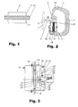
- Fig. 2 how out Fig. 2 can be seen, the guide rails 2 a connected via a web 6 with a rail foot 7 rail head 8, which the active surfaces of the guide rail forms, with which the braking or catching device according to the invention interacts after activation.
- a braking member in the form of a roller 9 is provided, which is close to its two lateral end faces (see Fig. 1 ) is provided with shoulders 11.
- the outermost lateral surface of the roller 9 serves as a friction surface 12.
- it is provided with a knurling or with a different profiling. The latter serves to reliably pull the roller (9) into the gap or roll it in until the roller (9) reaches its end position.
- the knurl also ensures that in the end position of the role at least no significant sliding between the roller (9) and the guide rail (2) occurs, but rolls the role on the guide rail.
- the Fig. 2 shows a braking or catching device 14 according to the invention in a horizontal section.
- the braking or catching device has a pressure body 19, which essentially corresponds to a U-profile, but u. U. could also have the cross section of a slotted circular or elliptical profile. Decisive is that the two legs 16, 17 in the region of their free ends, the guide rail 2 include.
- the pressure body 19 on its leg 16 on a gap-forming portion 20a which together with the corresponding guide rail forms a gap 20 in intended mounted braking device 14, in which the roller 9 is guided.
- the gap-forming portion 20a has a groove 21, which receives the friction surface 12 (see Fig.
- the pressure hull consists of a suitable tempering steel, as it is used for the production of screw and disc springs. Which tempering steels have hitherto been used for screw and disc springs is known to the person skilled in the art.
- the inventively necessary spring action is achieved by suitable design of the base body 19 as a U-profile or the like. Unlike spring steel, such tempered steel can be machined very easily.
- the roller 9 is rotatable on a z.
- axis 22 which, as of Fig. 3 illustrated, an opening 23 in the leg 16 (or in an attachment of the leg in the form of a holding plate 18) passes through and is held in a holder 25.
- the gap 20 is essentially limited on the one hand by the guide rail and on the other hand by the gap-forming portion 20a of the pressure hull.
- the contour of the gap-forming portion 20a corresponds to one of Fig. 8 shown contours. Each of these selectable contours corresponds to a specific response characteristic and a maximum achievable braking friction.
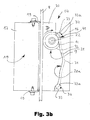
- a preferably V-shaped contoured locking surface 31 is provided between the up-driving and down-driving portions of the gap-forming portion in the embodiments of FIG Fig. 3b and 7 .
- This is designed so that the roller 9 (despite the inevitable friction influences) is retracted and held in almost always the same position at re-deactivation. This ensures z. B. a corresponding return spring, about as, as of the Fig. 3 and 7 shown.
- Fig. 3 or 3b shown embodiment uses a pivotable holder 25, which holds the role in rest position and possibly the movement of the role in the gap participates, as in detail in the prepublished international application WO 2006/077243 A1 which is referred to herein to avoid repetition, as to the pivotal holder or mechanism which serves to initiate the braking by bringing the roller into contact with the guide rail from the rest position and the roller later returns to their rest position.
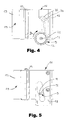
- Fig. 4 differs from that of the Fig. 3 . 3b and 7 Shown by the fact that it acts only unidirectionally and - as shown here - is primarily intended for the mechanical release by a fastened to the axis 22vonsbegrenzerseil. Both are optionally possible in all other embodiments.
- Said holder 25 is surrounded by a spring 28, which is designed as a compression spring and biases the roller 9 in the direction of the guide rail 2.
- This spring 28 counteracts a Soleniod (not shown), which is controlled by an electronic unit, not shown here, which is housed in the elevator shaft from which, if necessary, at least parts can also be installed cabin-fixed.
- the solenoid is de-energized when the braking or catching device should respond because either an emergency, ie an overspeed exists, or u. U. also because the elevator car is to be set in regular operation, z.
- the spring 28 moves the holder 25 and thus the roller 9 against the guide rail 2, so that this with its friction surface 12 (see Fig. 1 ) on the guide rail 2 (see Fig. 3 ) comes to the plant. It is thereby rotated, but also moved translationally relative to the pressure body 19. Namely, such that it soon not only touches the guide rail 2, but also the rear side, the groove 21, or, more precisely, the bottom of the groove 21st
- the roller 9 rotates clockwise (as viewed in FIG Fig. 3 ).
- the roller 9 once it has come back into contact with the bottom of the groove 21, with its friction surface or knurl 12 on the one hand on the guide rail 2 and on the other hand on the bottom of the groove 21.
- the roller 9 is getting deeper pulled into the wedge-shaped narrowing gap 20.
- the friction or contact conditions change on the role.
- the groove 21 is now so deep that the friction surface or knurl 12 loses contact with the bottom of the groove and the roller 9 rests on the pressure body side only with their shoulders 11 on the pressure body 19.
- the friction surface or knurl 12 has at least substantially clearance and the braking or catching friction is produced at least predominantly by the sliding of the shoulders 11 on the pressure body 19 or the fitting 33.
- the shoulders 11 predetermine the end position of the roll by pressing on the side of the press against a surface which is so steep that the roll can not be pulled further into the gap.
- the decisive first aspect of the invention in this context is in Fig. 3b to recognize.
- the pressure body 19 is provided with a fitting 33 of bearing metal, here in the form of bearing bronze. This is arranged and designed so that the shoulders 11 slide in the end position partially on the fitting 33 and partially directly on the base body, ie partially slide on the relative to the fitting 33 much firmer material of the body 19.
- a fitting 33 of bearing metal here in the form of bearing bronze.
- the fitting 33 is dimensioned and arranged so that the roller, once it has reached its end position, slides with part of the contact surface of its shoulders 11 on the fitting 33 consisting of bearing material and with the other part of the contact surface of its shoulders 11 on the harder material of the pressure hull 19. It goes without saying that the surface which represents the firmer of the two said sliding surfaces on the pressure body, does not necessarily have to be an integral part of the pressure hull 19, but z. B. also by a in the broadest sense attached to the actual pressure body, further fitting can be formed (not shown here, but claim variant).
- the roller or shoulders 11 of the roller are substantially harder or stronger than the bearing material of the fitting 33.
- the sliding of the shoulders 11 on the fitting 33 of the bearing material leads to a positive at the relatively high pressure that is encountered here
- This abrasion is introduced by the rotating roller in the surface area in which the roller with its shoulders 11 slides on the pressure body 19, and obviously fills the valleys of the surface roughness of the roller 9 on , It has been found that the abrasion can prevent effectively effective that it comes between the shoulders 11 of the roller 9 and the pressure body 19 to a seizure (local micro-welding and tearing) and thus destruction, as it is otherwise relatively quickly observed when steel slides under high surface pressure and speed on steel.
- the fitting 33 is subjected to significantly less wear by the roller than when the roller is fully or substantially exclusively slid on the fitting 33.
- the gap 20 or the gap-forming portion 20a can be designed so that the roller 9 in its End position a correspondingly higher pressure compared to the rail 2 and the pressure body 19 developed, resulting in a correspondingly higher, braking force acting frictional force results.
- the ratio of the surface with which the shoulders 11 slide in the final position of the roller 9 on the bearing material of the fitting 33 to the surface with which the shoulders 11 slide on the pressure body requires careful adjustment to the individual case.
- the surface with which the shoulders 11 of the roller 9 slide on the bearing material should not be unnecessarily large. Rather, it should be just so large that sufficient abrasion is generated to prevent between the shoulders 11 of the roller 9 and the Pressure body, where the greater part of the forces transmitted, seizure occurs.
- the expert can easily determine by experiments, as the area ratios are to be selected in the specific case.
- fittings 33 can be attached very easily.
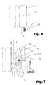
- a suitably directed bolt from the bearing material is used or-pressed.
- the column 20 and the grooves 21 are milled into the pressure body 19.
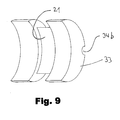
- the bearing pin is cut and thereby automatically receives the correct contour. Namely, a contour, which looks like when the again dismantled fitting Fig. 6 illustrated.
- over-milling is taken to ensure that at least locally more than 180 ° of the total circumference of the bolt remain, which ensures that the bolt can not fall out of the cut by the over-drilled hole in the body.
- roller 9 rotates counterclockwise during braking in upward direction and therefore in the lower of the two in Fig. 3 imaged gap 20 is pulled.
- the elevator car In order to deactivate the braking or catching device after the deceleration of a downward movement of the elevator car, the elevator car is driven a bit far up in all embodiments.
- the skew of the gap 20 and the groove 21 are selected and matched so that the roller does not slide along the guide rail during this upward movement of the elevator car, but is now driven inversely by it and in the direction of its inactive position in the area between the upward pointing back and the down-facing gap section rolls back.
- the roller Once the roller has come close to its inactive position, it is retracted to its rest position (correspondingly connected solenoid) in good time before the roller is torn into the descending portion of the gap 20 from the inactive position of the roller and now there unintentionally brakes.
- a recess 32 is provided to reduce the rigidity of the pressure body 19 in the lower region.
- a correspondingly lower rigidity is effected in the section corresponding to an upward travel of the pressure body 19, and thus a lower contact pressure of the roller 9, resulting in a lower deceleration during braking.
- the ramps are not mirror-symmetrical, but executed with a different pitch or length, which also sets the desired effect. The measures are generally useful, ie can be used profitably in all of the embodiments shown, if necessary.
- the Fig. 10 illustrates the second, independent aspect of the invention, according to which one of the braking or catching acting to be provided on a guide rail 2 provided surface 43 opposite to the rail head 8 associated surface of the guide rail 2 is inclined.
- the inclined surface 43 is designed here in the form of a friction lining 15. This is rigidly attached to the leg 17 of the pressure body 19.
- the friction lining thus does not move with respect to the entire pressure body, ie it does not carry out a relative movement with respect to the leg 17 holding it, but moves with the leg 17.
- it comes with fully expanded pressure body with its friction surface largely completely on the associated surface of the guide rail 2 to the plant, whereby optimal friction and loading conditions are achieved.
- the inclination of the invention is particularly effective to advantage when the pressure body 19, the elasticity ensures the correct installation of the inclined surface at full load, not rigidly attached to the car, but as well as Fig. 11 shown.
- the pressure body 19 is here, comparable to the saddle of a vehicle disc brake, floatingly mounted on the elevator car. Serve as a guide for the floating storage per brake or catching each two spaced apart from each other on the elevator car rail-like structure, here in the form of flat iron F, which form a substantially horizontally aligned rail pair, so to speak.
- the pressure body 19 is provided at its upper and lower edge in each case with a groove N1 or N2 for engagement for the said flat iron, so that the pressure body can be inserted between the two flat iron.
- Both grooves have, compared to the width of the flat iron, a certain lateral play on.
- at least one of the two grooves N1 and N2 on a special design namely, it runs altogether sufficiently inclined. This takes into account the fact that the pressure body is elastically bent under the influence of the force with which the roller is pulled into the gap in the case of braking or catching, so that the two grooves respectively attached to the underside and the upper side no longer be aligned, unless appropriate action is taken.
- the oblique course or the helix angle ⁇ of the at least one groove is ideally chosen such that the groove still provides a precisely defined guide provided with a permissible clearance when the braking or catching device is inactive, namely because the lower edge of the left and the upper edge of the right Groove flank unfold a defined guiding effect.
- the fact that the groove flanks are inclined, ensures that the pressure body can deform without hindrance, without affecting the leadership.
- the inclined surface 43 is inclined by an angle ⁇ between 0.5 ° and 5 °.
- the first and the second aspect of the invention are initially independent of each other, ie, the inclination is also useful if no fitting is provided from a bearing material on which the roller partially slides and vice versa. If both measures are applied together, the result is a strong one combinatorial effect. Because the partial sliding of the roller 19 on the fitting of bearing material allows at substantially the same pressure significantly higher sliding speeds between the roller 9 and the pressure body 19 - and just these significantly higher sliding speeds or (at constant sliding speed) pressures dictate it make sure that the surfaces of the braking or catching device that come into contact with the guide rail as intended come into contact with the guide rail at full load and not only have inefficient line contact there.
- the groove 21 does not necessarily have to be designed on the side of the pressure hull. Instead, the groove can also be made on the roll, where it is flanked on both sides by knurled peripheral portions of the roll.
- the gap-forming portion 20a of the pressure body is then formed complementary in a corresponding manner.
Landscapes
- Engineering & Computer Science (AREA)
- Mechanical Engineering (AREA)
- Braking Arrangements (AREA)
- Maintenance And Inspection Apparatuses For Elevators (AREA)
- Lift-Guide Devices, And Elevator Ropes And Cables (AREA)
- Bearings For Parts Moving Linearly (AREA)
- Coating Apparatus (AREA)
Priority Applications (7)
| Application Number | Priority Date | Filing Date | Title |
|---|---|---|---|
| EP07007905A EP1982945B9 (fr) | 2007-04-18 | 2007-04-18 | Dispositif de freinage ou d'arrêt avec rouleau tournant en partie sur un revêtement en bronze et avec surface de friction inclinée |
| AT07007905T ATE486811T1 (de) | 2007-04-18 | 2007-04-18 | Brems- bzw. fangeinrichtung mit teilweise auf bronzebelag laufender rolle und schräg stehender reibfläche |
| ES07007905T ES2353979T3 (es) | 2007-04-18 | 2007-04-18 | Dispositivo de frenado o aprehensión con rodillo que corre parcialmente sobre revestimiento de bronce y con superficie de fricción inclinada . |
| DE502007005550T DE502007005550D1 (de) | 2007-04-18 | 2007-04-18 | Brems- bzw. Fangeinrichtung mit teilweise auf Bronzebelag laufender Rolle und schräg stehender Reibfläche |
| PCT/EP2008/003034 WO2008128689A2 (fr) | 2007-04-18 | 2008-04-16 | Dispositif de freinage ou blocage à galet circulant sur garniture partiellement en bronze et surface de frottement oblique |
| RU2009137552/11A RU2438961C2 (ru) | 2007-04-18 | 2008-04-16 | Тормозное или ловильное устройство с частично перемещающимся по бронзовой накладке роликом и косо расположенной поверхностью трения |
| CN200880012697.7A CN101663221B (zh) | 2007-04-18 | 2008-04-16 | 一种用于电梯轿厢的制动器 |
Applications Claiming Priority (1)
| Application Number | Priority Date | Filing Date | Title |
|---|---|---|---|
| EP07007905A EP1982945B9 (fr) | 2007-04-18 | 2007-04-18 | Dispositif de freinage ou d'arrêt avec rouleau tournant en partie sur un revêtement en bronze et avec surface de friction inclinée |
Publications (3)
| Publication Number | Publication Date |
|---|---|
| EP1982945A1 true EP1982945A1 (fr) | 2008-10-22 |
| EP1982945B1 EP1982945B1 (fr) | 2010-11-03 |
| EP1982945B9 EP1982945B9 (fr) | 2011-02-02 |
Family
ID=38523505
Family Applications (1)
| Application Number | Title | Priority Date | Filing Date |
|---|---|---|---|
| EP07007905A Active EP1982945B9 (fr) | 2007-04-18 | 2007-04-18 | Dispositif de freinage ou d'arrêt avec rouleau tournant en partie sur un revêtement en bronze et avec surface de friction inclinée |
Country Status (7)
| Country | Link |
|---|---|
| EP (1) | EP1982945B9 (fr) |
| CN (1) | CN101663221B (fr) |
| AT (1) | ATE486811T1 (fr) |
| DE (1) | DE502007005550D1 (fr) |
| ES (1) | ES2353979T3 (fr) |
| RU (1) | RU2438961C2 (fr) |
| WO (1) | WO2008128689A2 (fr) |
Families Citing this family (3)
| Publication number | Priority date | Publication date | Assignee | Title |
|---|---|---|---|---|
| WO2017050647A1 (fr) * | 2015-09-23 | 2017-03-30 | Inventio Ag | Système de parachute à glissement pour système d'ascenseur |
| DE202019105584U1 (de) * | 2019-10-10 | 2019-10-22 | Wittur Holding Gmbh | Auslöseeinheit zum Betätigen einer Aufzugbremsvorrichtung |
| CN117446625A (zh) * | 2023-10-27 | 2024-01-26 | 杭州西奥电梯有限公司 | 一种分体涨紧式曳引轮衬套及组装方法 |
Citations (5)
| Publication number | Priority date | Publication date | Assignee | Title |
|---|---|---|---|---|
| GB2136773A (en) | 1983-03-21 | 1984-09-26 | Otis Elevator Co | Elevator safety device |
| EP0841280A1 (fr) | 1996-11-07 | 1998-05-13 | Kone Oy | Mécanisme de sécurité |
| EP1061032A1 (fr) * | 1998-12-02 | 2000-12-20 | Fabricacion de Elevadores, S.A. | Element elastique pour freins de systemes guides |
| WO2006077243A1 (fr) | 2005-01-21 | 2006-07-27 | Wittur Ag | Dispositif de freinage ou d'arret d'une cabine d'ascenseur |
| US20060180406A1 (en) * | 2004-12-17 | 2006-08-17 | Inventio Ag | Elevator installation with a braking device and method for braking and holding an elevator installation |
Family Cites Families (1)
| Publication number | Priority date | Publication date | Assignee | Title |
|---|---|---|---|---|
| SU1121225A1 (ru) * | 1980-08-22 | 1984-10-30 | Ордена Октябрьской Революции Карачаровский Механический Завод | Ловитель кабины лифта |
-
2007
- 2007-04-18 EP EP07007905A patent/EP1982945B9/fr active Active
- 2007-04-18 AT AT07007905T patent/ATE486811T1/de active
- 2007-04-18 ES ES07007905T patent/ES2353979T3/es active Active
- 2007-04-18 DE DE502007005550T patent/DE502007005550D1/de active Active
-
2008
- 2008-04-16 WO PCT/EP2008/003034 patent/WO2008128689A2/fr not_active Ceased
- 2008-04-16 CN CN200880012697.7A patent/CN101663221B/zh active Active
- 2008-04-16 RU RU2009137552/11A patent/RU2438961C2/ru active
Patent Citations (5)
| Publication number | Priority date | Publication date | Assignee | Title |
|---|---|---|---|---|
| GB2136773A (en) | 1983-03-21 | 1984-09-26 | Otis Elevator Co | Elevator safety device |
| EP0841280A1 (fr) | 1996-11-07 | 1998-05-13 | Kone Oy | Mécanisme de sécurité |
| EP1061032A1 (fr) * | 1998-12-02 | 2000-12-20 | Fabricacion de Elevadores, S.A. | Element elastique pour freins de systemes guides |
| US20060180406A1 (en) * | 2004-12-17 | 2006-08-17 | Inventio Ag | Elevator installation with a braking device and method for braking and holding an elevator installation |
| WO2006077243A1 (fr) | 2005-01-21 | 2006-07-27 | Wittur Ag | Dispositif de freinage ou d'arret d'une cabine d'ascenseur |
Also Published As
| Publication number | Publication date |
|---|---|
| CN101663221A (zh) | 2010-03-03 |
| ATE486811T1 (de) | 2010-11-15 |
| DE502007005550D1 (de) | 2010-12-16 |
| EP1982945B9 (fr) | 2011-02-02 |
| RU2009137552A (ru) | 2011-04-20 |
| ES2353979T3 (es) | 2011-03-08 |
| CN101663221B (zh) | 2013-01-30 |
| WO2008128689A3 (fr) | 2008-12-24 |
| RU2438961C2 (ru) | 2012-01-10 |
| EP1982945B1 (fr) | 2010-11-03 |
| WO2008128689A2 (fr) | 2008-10-30 |
Similar Documents
| Publication | Publication Date | Title |
|---|---|---|
| DE69718131T2 (de) | Sicherheitsvorrichtung | |
| EP2925654B1 (fr) | Dispositif antichute pour un corps mobile d'une installation de levage | |
| EP1902993B1 (fr) | Mécanisme de retour automatique pour un dispositif de freinage de type ABS | |
| DE102015206345A1 (de) | Führungsschiene für eine Aufzuganlage | |
| WO2021069739A1 (fr) | Unité de déclenchement destinée à actionner un dipsositif de freinage d'ascenseur | |
| DE3715098A1 (de) | Fangvorrichtung zum beispiel fuer den fahrkorb oder das gegengewicht einer aufzugsanlage | |
| EP1035965A1 (fr) | Transmission par courroie trapezoidale | |
| WO2006077243A1 (fr) | Dispositif de freinage ou d'arret d'une cabine d'ascenseur | |
| EP3710325B1 (fr) | Frein à commande électromécanique avec structure d'amortissement intégrale | |
| EP1400476B1 (fr) | Parachute pour ascenseurs | |
| DE69715773T2 (de) | Verschiebbare Sicherheitsvorrichtung | |
| DE102006036654B4 (de) | Keiltrieb mit Zwangsrückholeinrichtung | |
| EP4077190B1 (fr) | Dispositif d'arrêt pour un ascenseur | |
| EP1982945B9 (fr) | Dispositif de freinage ou d'arrêt avec rouleau tournant en partie sur un revêtement en bronze et avec surface de friction inclinée | |
| EP2102524B1 (fr) | Frein à disque comportant un actionneur à moteur électrique de type auto-amplifié | |
| EP2043937B1 (fr) | Dispositif de freinage ou de blocage destiné à la sécurisation temporaire d'un espace de sécurité et similaires | |
| EP0899231A1 (fr) | Dispositif de freinage à double action | |
| EP4217622A1 (fr) | Mécanisme d'application de frein d'un frein à disque | |
| EP3774629B1 (fr) | Frein à mâchoires pour une installation d'ascenseur, servant en particulier de frein de maintien et de sécurité | |
| EP4038002B1 (fr) | Dispositif de freinage | |
| DE102007038789A1 (de) | Spannvorrichtung und Anordnung einer solchen Spannvorrichtung mit einer Spannzange | |
| WO1985002169A1 (fr) | Dispositif parachute notamment pour cabines d'ascenseur | |
| EP4534466A2 (fr) | Unité de déclenchement destinée à actionner un dispositif de freinage d'ascenseur | |
| DE2133202A1 (de) | Nachstellvorrichtung fuer das lueftspiel einer durch federkraft einrueckbaren und elektromagnetisch geluefteten bremse | |
| DE102004001568A1 (de) | Teleskopschiene |
Legal Events
| Date | Code | Title | Description |
|---|---|---|---|
| PUAI | Public reference made under article 153(3) epc to a published international application that has entered the european phase |
Free format text: ORIGINAL CODE: 0009012 |
|
| 17P | Request for examination filed |
Effective date: 20080712 |
|
| AK | Designated contracting states |
Kind code of ref document: A1 Designated state(s): AT BE BG CH CY CZ DE DK EE ES FI FR GB GR HU IE IS IT LI LT LU LV MC MT NL PL PT RO SE SI SK TR |
|
| AX | Request for extension of the european patent |
Extension state: AL BA HR MK RS |
|
| 17Q | First examination report despatched |
Effective date: 20090306 |
|
| AKX | Designation fees paid |
Designated state(s): AT BE BG CH CY CZ DE DK EE ES FI FR GB GR HU IE IS IT LI LT LU LV MC MT NL PL PT RO SE SI SK TR |
|
| GRAP | Despatch of communication of intention to grant a patent |
Free format text: ORIGINAL CODE: EPIDOSNIGR1 |
|
| GRAS | Grant fee paid |
Free format text: ORIGINAL CODE: EPIDOSNIGR3 |
|
| GRAA | (expected) grant |
Free format text: ORIGINAL CODE: 0009210 |
|
| AK | Designated contracting states |
Kind code of ref document: B1 Designated state(s): AT BE BG CH CY CZ DE DK EE ES FI FR GB GR HU IE IS IT LI LT LU LV MC MT NL PL PT RO SE SI SK TR |
|
| REG | Reference to a national code |
Ref country code: GB Ref legal event code: FG4D Free format text: NOT ENGLISH |
|
| REG | Reference to a national code |
Ref country code: CH Ref legal event code: EP |
|
| REG | Reference to a national code |
Ref country code: IE Ref legal event code: FG4D Free format text: LANGUAGE OF EP DOCUMENT: GERMAN |
|
| REF | Corresponds to: |
Ref document number: 502007005550 Country of ref document: DE Date of ref document: 20101216 Kind code of ref document: P |
|
| REG | Reference to a national code |
Ref country code: ES Ref legal event code: FG2A Effective date: 20110224 |
|
| REG | Reference to a national code |
Ref country code: NL Ref legal event code: VDEP Effective date: 20101103 |
|
| LTIE | Lt: invalidation of european patent or patent extension |
Effective date: 20101103 |
|
| PG25 | Lapsed in a contracting state [announced via postgrant information from national office to epo] |
Ref country code: LT Free format text: LAPSE BECAUSE OF FAILURE TO SUBMIT A TRANSLATION OF THE DESCRIPTION OR TO PAY THE FEE WITHIN THE PRESCRIBED TIME-LIMIT Effective date: 20101103 |
|
| REG | Reference to a national code |
Ref country code: IE Ref legal event code: FD4D |
|
| PG25 | Lapsed in a contracting state [announced via postgrant information from national office to epo] |
Ref country code: LV Free format text: LAPSE BECAUSE OF FAILURE TO SUBMIT A TRANSLATION OF THE DESCRIPTION OR TO PAY THE FEE WITHIN THE PRESCRIBED TIME-LIMIT Effective date: 20101103 Ref country code: FI Free format text: LAPSE BECAUSE OF FAILURE TO SUBMIT A TRANSLATION OF THE DESCRIPTION OR TO PAY THE FEE WITHIN THE PRESCRIBED TIME-LIMIT Effective date: 20101103 Ref country code: SI Free format text: LAPSE BECAUSE OF FAILURE TO SUBMIT A TRANSLATION OF THE DESCRIPTION OR TO PAY THE FEE WITHIN THE PRESCRIBED TIME-LIMIT Effective date: 20101103 Ref country code: IS Free format text: LAPSE BECAUSE OF FAILURE TO SUBMIT A TRANSLATION OF THE DESCRIPTION OR TO PAY THE FEE WITHIN THE PRESCRIBED TIME-LIMIT Effective date: 20110303 Ref country code: PT Free format text: LAPSE BECAUSE OF FAILURE TO SUBMIT A TRANSLATION OF THE DESCRIPTION OR TO PAY THE FEE WITHIN THE PRESCRIBED TIME-LIMIT Effective date: 20110303 Ref country code: NL Free format text: LAPSE BECAUSE OF FAILURE TO SUBMIT A TRANSLATION OF THE DESCRIPTION OR TO PAY THE FEE WITHIN THE PRESCRIBED TIME-LIMIT Effective date: 20101103 Ref country code: SE Free format text: LAPSE BECAUSE OF FAILURE TO SUBMIT A TRANSLATION OF THE DESCRIPTION OR TO PAY THE FEE WITHIN THE PRESCRIBED TIME-LIMIT Effective date: 20101103 Ref country code: BG Free format text: LAPSE BECAUSE OF FAILURE TO SUBMIT A TRANSLATION OF THE DESCRIPTION OR TO PAY THE FEE WITHIN THE PRESCRIBED TIME-LIMIT Effective date: 20110203 |
|
| PG25 | Lapsed in a contracting state [announced via postgrant information from national office to epo] |
Ref country code: CZ Free format text: LAPSE BECAUSE OF FAILURE TO SUBMIT A TRANSLATION OF THE DESCRIPTION OR TO PAY THE FEE WITHIN THE PRESCRIBED TIME-LIMIT Effective date: 20101103 Ref country code: IE Free format text: LAPSE BECAUSE OF FAILURE TO SUBMIT A TRANSLATION OF THE DESCRIPTION OR TO PAY THE FEE WITHIN THE PRESCRIBED TIME-LIMIT Effective date: 20101103 Ref country code: EE Free format text: LAPSE BECAUSE OF FAILURE TO SUBMIT A TRANSLATION OF THE DESCRIPTION OR TO PAY THE FEE WITHIN THE PRESCRIBED TIME-LIMIT Effective date: 20101103 |
|
| PG25 | Lapsed in a contracting state [announced via postgrant information from national office to epo] |
Ref country code: DK Free format text: LAPSE BECAUSE OF FAILURE TO SUBMIT A TRANSLATION OF THE DESCRIPTION OR TO PAY THE FEE WITHIN THE PRESCRIBED TIME-LIMIT Effective date: 20101103 Ref country code: PL Free format text: LAPSE BECAUSE OF FAILURE TO SUBMIT A TRANSLATION OF THE DESCRIPTION OR TO PAY THE FEE WITHIN THE PRESCRIBED TIME-LIMIT Effective date: 20101103 Ref country code: RO Free format text: LAPSE BECAUSE OF FAILURE TO SUBMIT A TRANSLATION OF THE DESCRIPTION OR TO PAY THE FEE WITHIN THE PRESCRIBED TIME-LIMIT Effective date: 20101103 Ref country code: SK Free format text: LAPSE BECAUSE OF FAILURE TO SUBMIT A TRANSLATION OF THE DESCRIPTION OR TO PAY THE FEE WITHIN THE PRESCRIBED TIME-LIMIT Effective date: 20101103 |
|
| PLBE | No opposition filed within time limit |
Free format text: ORIGINAL CODE: 0009261 |
|
| STAA | Information on the status of an ep patent application or granted ep patent |
Free format text: STATUS: NO OPPOSITION FILED WITHIN TIME LIMIT |
|
| 26N | No opposition filed |
Effective date: 20110804 |
|
| BERE | Be: lapsed |
Owner name: WITTUR HOLDING G.M.B.H. Effective date: 20110430 |
|
| PG25 | Lapsed in a contracting state [announced via postgrant information from national office to epo] |
Ref country code: MC Free format text: LAPSE BECAUSE OF NON-PAYMENT OF DUE FEES Effective date: 20110430 |
|
| REG | Reference to a national code |
Ref country code: CH Ref legal event code: PL |
|
| REG | Reference to a national code |
Ref country code: DE Ref legal event code: R097 Ref document number: 502007005550 Country of ref document: DE Effective date: 20110804 |
|
| PG25 | Lapsed in a contracting state [announced via postgrant information from national office to epo] |
Ref country code: MT Free format text: LAPSE BECAUSE OF FAILURE TO SUBMIT A TRANSLATION OF THE DESCRIPTION OR TO PAY THE FEE WITHIN THE PRESCRIBED TIME-LIMIT Effective date: 20101103 |
|
| PG25 | Lapsed in a contracting state [announced via postgrant information from national office to epo] |
Ref country code: LI Free format text: LAPSE BECAUSE OF NON-PAYMENT OF DUE FEES Effective date: 20110430 Ref country code: CH Free format text: LAPSE BECAUSE OF NON-PAYMENT OF DUE FEES Effective date: 20110430 Ref country code: BE Free format text: LAPSE BECAUSE OF NON-PAYMENT OF DUE FEES Effective date: 20110430 |
|
| REG | Reference to a national code |
Ref country code: DE Ref legal event code: R082 Ref document number: 502007005550 Country of ref document: DE Representative=s name: MARTIN MISSELHORN PATENT- UND RECHTSANWALT, DE Ref country code: DE Ref legal event code: R082 Ref document number: 502007005550 Country of ref document: DE Representative=s name: MISSELHORN WALL PATENT- UND RECHTSANWAELTE, DE |
|
| PG25 | Lapsed in a contracting state [announced via postgrant information from national office to epo] |
Ref country code: LU Free format text: LAPSE BECAUSE OF NON-PAYMENT OF DUE FEES Effective date: 20110418 Ref country code: CY Free format text: LAPSE BECAUSE OF FAILURE TO SUBMIT A TRANSLATION OF THE DESCRIPTION OR TO PAY THE FEE WITHIN THE PRESCRIBED TIME-LIMIT Effective date: 20101103 |
|
| REG | Reference to a national code |
Ref country code: DE Ref legal event code: R082 Ref document number: 502007005550 Country of ref document: DE Representative=s name: MARTIN MISSELHORN PATENT- UND RECHTSANWALT, DE |
|
| REG | Reference to a national code |
Ref country code: AT Ref legal event code: MM01 Ref document number: 486811 Country of ref document: AT Kind code of ref document: T Effective date: 20120418 |
|
| PG25 | Lapsed in a contracting state [announced via postgrant information from national office to epo] |
Ref country code: AT Free format text: LAPSE BECAUSE OF NON-PAYMENT OF DUE FEES Effective date: 20120418 |
|
| PG25 | Lapsed in a contracting state [announced via postgrant information from national office to epo] |
Ref country code: HU Free format text: LAPSE BECAUSE OF FAILURE TO SUBMIT A TRANSLATION OF THE DESCRIPTION OR TO PAY THE FEE WITHIN THE PRESCRIBED TIME-LIMIT Effective date: 20101103 |
|
| REG | Reference to a national code |
Ref country code: DE Ref legal event code: R082 Ref document number: 502007005550 Country of ref document: DE Representative=s name: MISSELHORN, MARTIN, DIPL.-ING., DE Effective date: 20131114 Ref country code: DE Ref legal event code: R082 Ref document number: 502007005550 Country of ref document: DE Representative=s name: MISSELHORN, MARTIN, DIPL.-ING., DE Effective date: 20120402 Ref country code: DE Ref legal event code: R082 Ref document number: 502007005550 Country of ref document: DE Representative=s name: MISSELHORN, MARTIN, DIPL.-ING., DE Effective date: 20130614 Ref country code: DE Ref legal event code: R081 Ref document number: 502007005550 Country of ref document: DE Owner name: WITTUR HOLDING GMBH, DE Free format text: FORMER OWNER: WITTUR HOLDING GMBH, 85259 WIEDENZHAUSEN, DE Effective date: 20131114 |
|
| REG | Reference to a national code |
Ref country code: GR Ref legal event code: EP Ref document number: 20100403037 Country of ref document: GR Effective date: 20110119 |
|
| REG | Reference to a national code |
Ref country code: FR Ref legal event code: PLFP Year of fee payment: 10 |
|
| REG | Reference to a national code |
Ref country code: FR Ref legal event code: PLFP Year of fee payment: 11 |
|
| REG | Reference to a national code |
Ref country code: FR Ref legal event code: PLFP Year of fee payment: 12 |
|
| PGFP | Annual fee paid to national office [announced via postgrant information from national office to epo] |
Ref country code: GR Payment date: 20230418 Year of fee payment: 17 |
|
| PG25 | Lapsed in a contracting state [announced via postgrant information from national office to epo] |
Ref country code: GR Free format text: LAPSE BECAUSE OF NON-PAYMENT OF DUE FEES Effective date: 20241104 |
|
| PG25 | Lapsed in a contracting state [announced via postgrant information from national office to epo] |
Ref country code: GR Free format text: LAPSE BECAUSE OF NON-PAYMENT OF DUE FEES Effective date: 20241104 |
|
| PGFP | Annual fee paid to national office [announced via postgrant information from national office to epo] |
Ref country code: DE Payment date: 20250417 Year of fee payment: 19 |
|
| PGFP | Annual fee paid to national office [announced via postgrant information from national office to epo] |
Ref country code: GB Payment date: 20250423 Year of fee payment: 19 Ref country code: ES Payment date: 20250519 Year of fee payment: 19 |
|
| PGFP | Annual fee paid to national office [announced via postgrant information from national office to epo] |
Ref country code: IT Payment date: 20250430 Year of fee payment: 19 |
|
| PGFP | Annual fee paid to national office [announced via postgrant information from national office to epo] |
Ref country code: FR Payment date: 20250428 Year of fee payment: 19 |
|
| PGFP | Annual fee paid to national office [announced via postgrant information from national office to epo] |
Ref country code: TR Payment date: 20250410 Year of fee payment: 19 |