EP0841280A1 - Mécanisme de sécurité - Google Patents
Mécanisme de sécurité Download PDFInfo
- Publication number
- EP0841280A1 EP0841280A1 EP97118920A EP97118920A EP0841280A1 EP 0841280 A1 EP0841280 A1 EP 0841280A1 EP 97118920 A EP97118920 A EP 97118920A EP 97118920 A EP97118920 A EP 97118920A EP 0841280 A1 EP0841280 A1 EP 0841280A1
- Authority
- EP
- European Patent Office
- Prior art keywords
- roller
- safety gear
- gradient
- track
- guide rail
- Prior art date
- Legal status (The legal status is an assumption and is not a legal conclusion. Google has not performed a legal analysis and makes no representation as to the accuracy of the status listed.)
- Granted
Links
Images


Classifications
-
- B—PERFORMING OPERATIONS; TRANSPORTING
- B66—HOISTING; LIFTING; HAULING
- B66B—ELEVATORS; ESCALATORS OR MOVING WALKWAYS
- B66B5/00—Applications of checking, fault-correcting, or safety devices in elevators
- B66B5/02—Applications of checking, fault-correcting, or safety devices in elevators responsive to abnormal operating conditions
- B66B5/16—Braking or catch devices operating between cars, cages, or skips and fixed guide elements or surfaces in hoistway or well
- B66B5/18—Braking or catch devices operating between cars, cages, or skips and fixed guide elements or surfaces in hoistway or well and applying frictional retarding forces
- B66B5/22—Braking or catch devices operating between cars, cages, or skips and fixed guide elements or surfaces in hoistway or well and applying frictional retarding forces by means of linearly-movable wedges
-
- F—MECHANICAL ENGINEERING; LIGHTING; HEATING; WEAPONS; BLASTING
- F16—ENGINEERING ELEMENTS AND UNITS; GENERAL MEASURES FOR PRODUCING AND MAINTAINING EFFECTIVE FUNCTIONING OF MACHINES OR INSTALLATIONS; THERMAL INSULATION IN GENERAL
- F16D—COUPLINGS FOR TRANSMITTING ROTATION; CLUTCHES; BRAKES
- F16D63/00—Brakes not otherwise provided for; Brakes combining more than one of the types of groups F16D49/00 - F16D61/00
- F16D63/008—Brakes acting on a linearly moving member
-
- F—MECHANICAL ENGINEERING; LIGHTING; HEATING; WEAPONS; BLASTING
- F16—ENGINEERING ELEMENTS AND UNITS; GENERAL MEASURES FOR PRODUCING AND MAINTAINING EFFECTIVE FUNCTIONING OF MACHINES OR INSTALLATIONS; THERMAL INSULATION IN GENERAL
- F16D—COUPLINGS FOR TRANSMITTING ROTATION; CLUTCHES; BRAKES
- F16D2127/00—Auxiliary mechanisms
- F16D2127/007—Auxiliary mechanisms for non-linear operation
-
- F—MECHANICAL ENGINEERING; LIGHTING; HEATING; WEAPONS; BLASTING
- F16—ENGINEERING ELEMENTS AND UNITS; GENERAL MEASURES FOR PRODUCING AND MAINTAINING EFFECTIVE FUNCTIONING OF MACHINES OR INSTALLATIONS; THERMAL INSULATION IN GENERAL
- F16D—COUPLINGS FOR TRANSMITTING ROTATION; CLUTCHES; BRAKES
- F16D2127/00—Auxiliary mechanisms
- F16D2127/08—Self-amplifying or de-amplifying mechanisms
- F16D2127/10—Self-amplifying or de-amplifying mechanisms having wedging elements
Definitions
- the present invention relates to a safety gear as defined in the preamble of claim 1.
- Elevators are equipped with automatic braking devices acting as safety gears designed to stop the elevator if its speed rises too much.
- the braking device used is a gripper type brake that grips a guide rail.
- the safety gear is used to stop downward movement.
- Such a gripping brake can also be used to stop the elevator for other reasons, e.g. in a case where an error in operation results in the elevator leaving a door zone with doors open.
- the basic structure of a conventional brake gripping a guide rail, a safety gear is as follows.
- the safety gear frame contains a hollow with a braking surface facing towards a guide rail placed in the hollow.
- Placed in the hollow is also a wedge or a roller, which, mounted on a track in the hollow, is driven against the elevator guide rail when the safety gear is activated.
- the elevator guide rail is placed between the braking surface and the wedge or roller.
- the track is so shaped that, when the wedge or roller moves on the track in the direction of the guide rail, the guide rail is pressed by the wedge or roller against the braking surface, thus producing a braking action that stops the elevator car.
- the safety gear can also be mounted on the counterweight.
- the compression applied by the safety gear to the guide rail is set by means of a spring. Via the friction between the braking surface and the guide rail, the magnitude of the compressive force determines the deceleration of the elevator.
- the use of spring-loaded compression compensates the variations in compressive force occurring during the deceleration.
- a commonly used safety gear type is a large U-shaped spring made of spring steel, with a wedge which is driven between the ends of the spring when the safety gear is activated. Safety gears of this type are also often provided with a release wedge for easier disengagement from the guide rail.
- safety gears have also been developed in which the safety gear frame is relatively rigid and the springiness of the compression applied by the safety gear to the guide rail is achieved using separate springs.
- these safety gears comprise a large number of separate parts and they are more complex in composition.
- Such safety gears are lighter than earlier safety gear types, but like these, they are quite expensive.
- a roller track with a changing gradient has been used in some safety gears employing a roller to engage the guide rail.
- the purpose of the steeper gradient at the beginning of a track with changing gradient is to quickly eliminate the clearance between the guide rail and the friction surface of the safety gear in the initial stage of safety gear operation.
- the gradient of the first part of the track cannot be increased very much because a steeper track would result in jeopardising the ascent of the roller to the part of the track that produces the actual braking force or, to ensure the ascent of the roller to the part of the track that produces the braking force, in a necessity to move the roller using a larger force from the overspeed governor.
- the force obtained from the overspeed governor cannot be increased very much because even the regulations relating to elevator structure and safety impose certain upper and lower limits on the force generated by the overspeed governor for the triggering of safety gears.
- the safety gear of the invention is characterized by what is presented in the characterization part of claim 1.
- Other embodiments of the invention are characterized by what is presented in the other claims.
- the advantages achieved by the invention include the following:
- the safety gear is relatively light and reliable in operation.
- the safety gear of the invention is also of a short construction and does not require much space, so it is easy to place in the elevator layout as well as easy to install.
- its roller is reliably and sickly moved to the position where braking is started.
- the elevator speed cannot rise too much during free fall before braking is started.
- a high average braking force is achieved in relation to the maximum gripping force on the basis of which the strength properties of the safety gear have to be designed.
- the average braking force or deceleration is decisive in determining the safety gear size in relation to the elevator.
- the invention makes it possible to reduce the design strength of the safety gear, in other words, a smaller size and lower weight will be sufficient.
- a low maximum force means that a low releasing force is achieved, which makes it easier to resume elevator operation after safety gear action.
- the safety gear of the invention is suited for use in different types of elevator.
- the safety gear of the invention is of simple composition and plain construction and contains a small number of separate parts, so it is also cheap to manufacture.
- As the structure of the safety gear helps prevent misalignment between the guide rail and the braking surface, it causes less wear of the guide rail and is also less liable to wear. A low maximum force also means less wear of the guide rail.
- the safety gear is very durable.
- the roller track comprises at least two levels differing from each other in gradient.
- a two-level roller track provides the advantage that the safety gear can be made to smaller external dimensions.
- the first, steeper gradient serves to eliminate the clearance between the friction surface and the guide rail. At this stage, the forces applied to the safety gear are small and do not yet produce actual braking. Because of the steep gradient, a large friction between the roller and the roller track is necessary. This is achieved e.g. by using a roller with a scalloped surface meeting a roller track that is definitely softer than the scalloping.
- the safety gear produces a steadily increasing braking force, which becomes a constant force once the roller has reached a stopper at the end of the track.
- the contact surfaces between the roller and the roller track in the area of the second gradient should be hard and smooth, made e.g. of hardened steel, to ensure that they undergo no permanent deformations or wear that would affect the braking force. It is further advantageous to have a large contact area between the roller and the roller track because in that case the safety gear need not necessarily be provided with a separate roller guide. Since the contact surfaces in the area of the second gradient are smooth, their friction coefficient is lower as compared with the first gradient, which is why the second gradient must also have a gentler pitch angle.
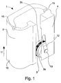
- Fig. 1 presents a safety gear 1 applying the invention.
- the main parts of the safety gear 1 are a frame 2, a force element 3 and a guard 4 supporting and guiding the force element.
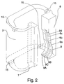
- a more detailed view of the frame 2 is shown in Fig. 2.
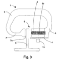
- Fig. 3 shows a cross-section of the safety gear 1.
- the elevator guide rail 5 is placed in the gap 6 of the safety gear.
- the frame 2 is a flexible body, made e.g. of spring steel or quenched and subsequently drawn steel, of a shape substantially resembling the letter C.
- the first jam 7 of the C-shaped frame is provided with a braking surface 7a, while the second jam 8 is provided with a force element. At least one of the jams 7,8 is bent to the inside of the C-shape of the frame 2.
- the braking surface 7a on the first jam is either implemented as an integral part of the frame or it is part of a brake pad attached to the first jam.
- the braking surface is preferably an integral part of the frame 2.
- the force element 3 is a roller movable along a track 9 on the second jam 8. In a safety gear mounted in place, the elevator guide rail goes between the braking surface 7a and the roller. The roller 3 is held on the track 9 in the second jam 8 by the guard 4.
- the track 9 preferably has a curvilinear gradient at least in part of the path of the roller.
- the safety gear is activated by moving the roller along the sloping track 9 until it grips the guide rail.
- the track 9 can be implemented as a separate part attached to the frame, the track 9 is preferably integrated with the frame 2 and, in a further preferred case, the track 9 is machined directly in the second jam 8 of the frame 2.
- the upper and lower ends of the frame are provided with notches 15, by which the safety gear is fastened to a mounting structure in the elevator car or car frame.
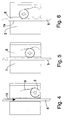
- Figures 4, 5 and 6 present the safety gear 1 as seen from the direction of the gap between the jams 7,8 of the C-shaped frame, illustrating the gripping process.
- a guide rail 5 fixed in the elevator shaft is in the gap.
- the safety gear grips the guide rail.
- the track 9 has a changing gradient, as is clearly shown in Fig. 2.
- the first part 9a of the track gradient where a transmitting element connected to the overspeed governor of the elevator pulls the roller 3 upwards - the up direction being indicated by arrow 11 - causing the roller to engage the guide rail, has a relatively large angle of inclination relative to the direction of the guide rail, preferably 15-25°. With an angle of about 20°, the faster safety gear action and reliable operation achieved by the invention are accomplished well enough to satisfy practical needs. If the first gradient is below 15°, e.g. 10°, safety gear action is faster than when no separate gradient for eliminating the clearance is used, but the speed advantage is still proportionally smaller.
- the pitch angle of the first gradient could be increased to above 30° and even to about 45°, However, very large pitch angles will make it more difficult to achieve a sufficient grip on both the guide rail and the track simultaneously.
- the middle part 9b of the track where the roller moving on the track presses the guide rail between the roller and the braking surface, has a smaller angle of inclination, preferably 5-8°, most advantageously about 7°. If the pitch angle is very large, this might easily lead to a need to use, in the second gradient and in those parts of the roller that come into contact with it, surfaces having a lower wear resistance than that of the surfaces that would be needed if the pitch angle were smaller.
- a preferred shape of the stopper 9d is one that provides support for the roller over a large area, for instance a concave cylinder sector surface having the same radius of curvature as the rolling surface 3a of the roller 3 has.
- the roller 3 may be provided with a roughened surface or a surface pattern raised from the roller surface.
- the roller 3 is definitely harder than the surface of the guide rail 5, at least in this roughened or patterned area, so that even a moderate surface pressure will produce an excellent grip on the guide rail.
- the hardness of the guide rail is in the range of 180 HB (Brinell scale) and the hardness of a hardened steel roller is in the range of 55-65 HRC (Rockwell C scale).
- roller whose surface can be further case hardened to about 58 HRC.
- the roller is preferably at least somewhat harder than the second gradient and much harder than the guide rail and the first gradient.
- the safety gear friction surface engaging the guide rail is of the same order of hardness as the surface of the roller and the second gradient.
- Such a roughened area or surface pattern raised from the roller surface is preferably implemented as a ring-shaped bossage 3b in the middle of the cylindrical surface of the roller, dividing its rolling surface 3a into two parts.
- the bossage 3b is preferably a substantially cylindrical surface coaxial with the rolling surface 3a and larger than the latter in diameter.
- the sides of the track 9 that meet the roller 3 during actual braking form two parallel sub-tracks 9A,9B with a cut-out 9C between them in which the bossage is to run.
- the cut-out In the first part 9a of the track, the cut-out has a depth smaller than the height of the bossage 3b, but in the final part 9b,9c,9d of the track it has a depth larger than the height of the bossage.
- This cut-out can also act as a guide groove which guides the roller in the lateral direction by its bossage 3b.
- the roller 3 is supported by the cut-out via the ring-like bossage 3b, which preferably has a roughened surface, while in the rest 9b,9c,9d of the track 9 it is supported by the parallel sub-tracks 9A,9B via its smooth rolling surface 3a.
- Figures 4-6 illustrate the gripping process.
- the roller is still in its low position.
- the long guide hole 12 in the guard 4 (shown in Fig. 1) keeps the roller 3 in position at the lower end of the track 9.
- the roller is supported on the guard by its journal 13, which is placed in the guide hole 12.
- the roller 3 has ascended along the first part 9a of the track 9, which acts as a first gradient, to the middle part 9b, which acts as a second gradient, where the roller movement presses the guide rail 5 more and more tightly between the roller 3 and the braking surface 7a.
- the primary function of the first gradient in the operation of the safety gear is to eliminate the clearance between the guide rail and the friction surface of the safety gear and the function of the second gradient is to increase the gripping force.
- the transition to the second gradient can also be so implemented that the roller meets the bottom of the cut-out for a short time at the beginning of the second gradient.
- the first part 9a of the track at least in the cut-out 9C is made of a softer material than the ring-like bossage 3 of the roller. In this way, the roller will properly engage the track via its roughened or scalloped surface.
- the rotation of the roller between the guide rail and the track ensures that the roller will climb up along the first part 9a of the track to the next part 9b.
- the point of contact between the roller and the track changes from the cut-out 9C to the parallel sub-tracks 9A,9B.
- the roller has already reached the stopper 9d, where the roller can rotate.
- the roller presses the guide rail 5 against the braking surface 7a with full force.
- the friction between the roller 3 and the frame 2 brakes the rotation of the roller in the stopper 9d.
- a dual braking action occurs in the safety gear, viz., on the one hand, as the braking surface 7a is sliding along the guide rail 5 and, on the other hand, as the roller 3 is rotating in the stopper 9d.
- the sub-tracks 9A,9B must be hard and smooth because of the high surface pressure applied to the track by the roller 3; this applies especially to the stopper 9d. Otherwise there is a risk of fast wear of the track.
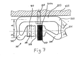
- FIG. 7 shows a cross-section of the safety gear 101 and especially its frame 102.
- the cross-section is substantially the shape of the letter C.
- the back 103 of the C-shape is thicker than its jams 104,105.
- a hollow 106 housing a roller, which, when the safety gear is activated, is pressed against an elevator guide rail 107, thus acting as a force element.
- the safety gear 101 is attached by its back 103 with a bolt 120 or other suitable means to a load-bearing part 121 of the elevator car or counterweight.
- the safety gear 101 starts braking when the force element, which in Fig. 9 is a roller 108, is brought into contact with the guide rail 107.
- the force element which in Fig. 9 is a roller 108
- it will move up along the track 109, getting more and more tightly crammed between the guide rail and the second jam 105, until finally the guide rail is squeezed between the force element engaging the rail from its second side and the braking surface 104a engaging the rail from its first side.
- the jams 104,105 of the safety gear 101 move farther apart from each other; the C-shape tends to open out, as it were.
- the line 114 of application of the force producing this opening movement of the jams passes through the braking surface 104a in a substantially perpendicular direction.
- This line 114 of application of the force also passes through the inside of the C-shape of the cross-section of the safety gear so that the back 103 of the C-shape remains on one side of the line while the jams 104,105 of the C-shape remain on the other side, at least partially.
- the gripping force of the safety gear consists of the frictional force acting via the braking surface 104a and, on the other hand, when the force element 108 is active.
- the force element 108 is placed in a box-like guide support 110, which also supports the force element to keep it in position. Fig.
- the force element is supported by a track consisting of two parallel sub-tracks 109A,109B, with a supporting force acting in a direction opposite to force F.
- the components of the supporting force applied to the adjacent sub-tracks 109A,109B are of equal magnitude and therefore their magnitudes are F/2.
- the gradients of the sub-tracks may differ somewhat from each other.
- the force element In the second jam the force element is supported. Since the safety gear frame acts as a spring, force F is substantially proportional to the displacement by which the C-shape opens out.
- the degree of the opening movement of the frame 102 and, on the other hand, the degree of bending of the jams 104,105 to the inside of the C-shape are adjusted by selecting the thicknesses of the various parts of the frame, e.g. the thicknesses C and D of the bends of jam 104, and via the design of the C-shape and its parts and the position of the line of application of the force.
- the design should be such that line of application of the force passes through the thinner parts of the jams in a direction parallel to the back 103.
- Fig. 9 presents the safety gear 101 as seen from the direction of the gap between the jams 104,105 of the C-shape.
- a guide rail 107 fixed in place in the elevator shaft.
- the safety gear grips the guide rail.
- the force element is a roller 108.
- the track 109 has a changing gradient.
- the first part of the track gradient where a transmitting element 112 connected to the overspeed governor of the elevator pulls the roller 108a upwards - the up direction being indicated by arrow 113 - causing the roller to engage the guide rail, has a relatively large angle of inclination relative to the direction of the guide rail, preferably 10-11°.
- the middle part of the track where the roller moving on the track presses the guide rail between the roller and the braking surface, has a smaller angle of inclination, preferably 5-8°.
- the final compressive force applied by the safety gear to the guide rail is reached at the end of the middle part.
- a roller stopper which in a braking situation keeps the roller in a specified position in the longitudinal direction of the safety gear 101, preferably about midway between the ends of the safety gear.
- a preferred shape of the stopper is one that provides support for the roller over a large area, for instance a concave cylinder sector surface having the same radius of curvature as the rolling surface of the roller has.
- Fig. 10 presents a safety gear 201 like the one depicted in Fig. 1-6.
- the braking surface of the safety gear that is pressed against the guide rail is divided into a number of successive sub-surfaces 202,203,204,205,206 by transverse grooves 207,208,209,210. If the elevator is provided with sliding guides, the guide rail may be very greasy. In this case, the grease may retard the beginning of the braking.
- the transverse grooves allow the grease to escape from between the braking surface and the guide rail during safety gear operation, resulting in faster gripping.
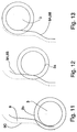
- Figures 11-13 give a detailed illustration the motion of the roller 3 along the track 9 in a gripping process as presented in Fig. 4-6.
- the thrust of the roller 3 is received via the bossage 3b in the roller surface by the bottom 9C of the cut-out in the track 9.
- the roller may be provided with a roughening or patterning raised from the roller surface to ensure a secure grip on the relatively soft surface of the first part of the track.
- the roller is moving from a steep-gradient part of the track to a part with a gentler gradient.
- the roller 3 is disengaged from the track bottom 9C and is from then on supported by the subtracks 9A,9B beside the cut-out.
- the roller now has track contact via its rolling surface 3a.
- the roller has reached the end of the track 9, which is so shaped as to stop the roller while permitting it to rotate.
- the roller is pressed against the guide rail and the stopper with full force.
- the friction between the roller 3 and the track 9 has a braking effect on the rotation of the roller.
- the surface receiving the rolling surface of the roller is harder.
- various methods to make a track with different degrees of hardness in different parts of it For instance, heat treatment can be used to soften desired parts of a hardened track. It is possible to harden only certain parts of the track to make them harder than the rest.
- Another possibility is to assemble the track from parts of different degrees of hardness.
- the roughening or patterning raised from the surface of the roller is preferably implemented as a ring-shaped bossage 3b in the middle of the cylindrical surface of the roller, dividing the rolling surface 3a into two parts.
Landscapes
- Engineering & Computer Science (AREA)
- Mechanical Engineering (AREA)
- General Engineering & Computer Science (AREA)
- Maintenance And Inspection Apparatuses For Elevators (AREA)
- Braking Arrangements (AREA)
- Table Equipment (AREA)
- Types And Forms Of Lifts (AREA)
Applications Claiming Priority (4)
| Application Number | Priority Date | Filing Date | Title |
|---|---|---|---|
| FI964484A FI101782B (fi) | 1996-11-07 | 1996-11-07 | Liukutarraaja |
| FI964484 | 1996-11-07 | ||
| FI964903A FI103962B1 (fi) | 1996-11-07 | 1996-12-05 | Tarraaja |
| FI964903 | 1996-12-05 |
Publications (2)
| Publication Number | Publication Date |
|---|---|
| EP0841280A1 true EP0841280A1 (fr) | 1998-05-13 |
| EP0841280B1 EP0841280B1 (fr) | 2003-01-02 |
Family
ID=26160248
Family Applications (1)
| Application Number | Title | Priority Date | Filing Date |
|---|---|---|---|
| EP97118920A Expired - Lifetime EP0841280B1 (fr) | 1996-11-07 | 1997-10-30 | Mécanisme de sécurité |
Country Status (12)
| Country | Link |
|---|---|
| US (1) | US6109398A (fr) |
| EP (1) | EP0841280B1 (fr) |
| JP (1) | JP3405670B2 (fr) |
| KR (1) | KR100335820B1 (fr) |
| CN (1) | CN1086999C (fr) |
| AU (1) | AU720534B2 (fr) |
| BR (1) | BR9705444A (fr) |
| CA (1) | CA2218794C (fr) |
| DE (1) | DE69718131T2 (fr) |
| ES (1) | ES2188849T3 (fr) |
| FI (1) | FI103962B1 (fr) |
| IN (1) | IN191648B (fr) |
Cited By (11)
| Publication number | Priority date | Publication date | Assignee | Title |
|---|---|---|---|---|
| EP1400476A1 (fr) * | 2002-09-23 | 2004-03-24 | Inventio Ag | Parachute pour ascenseurs |
| WO2006077243A1 (fr) * | 2005-01-21 | 2006-07-27 | Wittur Ag | Dispositif de freinage ou d'arret d'une cabine d'ascenseur |
| WO2007023051A1 (fr) * | 2005-08-24 | 2007-03-01 | Robert Bosch Gmbh | Frein a friction auto-amplificateur |
| WO2008011896A1 (fr) * | 2006-07-26 | 2008-01-31 | Wittur Ag | Dispositif de freinage ou de blocage destiné à la sécurisation temporaire d'un espace de sécurité et similaires |
| DE102006043890A1 (de) * | 2006-09-19 | 2008-03-27 | Wittur Ag | Selbstrückstellmechanismus für eine Bremsfangeinrichtung Typ BSG |
| US7398863B2 (en) | 2002-09-23 | 2008-07-15 | Inventio Ag | Safety device for elevators |
| EP1982945A1 (fr) | 2007-04-18 | 2008-10-22 | Wittur Holding GmbH | Dispositif de freinage ou d'arrêt avec rouleau tournant en partie sur un revêtement en bronze et avec surface de friction inclinée |
| CN101941626A (zh) * | 2010-09-09 | 2011-01-12 | 昆山京都电梯有限公司 | 一种用于电梯的安全钳连动机构 |
| WO2011078862A1 (fr) | 2009-12-23 | 2011-06-30 | Otis Elevator Company | Dispositif de freinage d'ascenseur |
| WO2012128758A1 (fr) | 2011-03-22 | 2012-09-27 | Otis Elevator Company | Système de freinage d'ascenseur |
| WO2022069355A1 (fr) | 2020-10-01 | 2022-04-07 | Inventio Ag | Frein de sécurité à stabilisation de rail |
Families Citing this family (23)
| Publication number | Priority date | Publication date | Assignee | Title |
|---|---|---|---|---|
| JP4109384B2 (ja) * | 1999-05-27 | 2008-07-02 | 三菱電機株式会社 | エレベータ調速機 |
| US6427795B1 (en) * | 1999-10-29 | 2002-08-06 | Caterpillar Elphinstone Pty. Ltd. | Underground roll over protection structure |
| CN100591603C (zh) * | 2003-04-15 | 2010-02-24 | 奥蒂斯电梯公司 | 具有带有可选择的可变硬度的滚子的升降机 |
| US7543686B2 (en) * | 2003-04-15 | 2009-06-09 | Otis Elevator Company | Elevator with rollers having selectively variable hardness |
| US20070240941A1 (en) * | 2005-12-21 | 2007-10-18 | Daniel Fischer | Brake shoe for use in elevator safety gear |
| WO2009018434A1 (fr) * | 2007-07-31 | 2009-02-05 | Thyssenkrupp Elevator Capital Corporation | Procédé et appareil pour réduire à un minimum la remise à niveau des ascenseurs à vitesse élevée dans des immeubles de grande hauteur |
| FI20106273A (fi) * | 2010-12-01 | 2012-06-02 | Kone Corp | Hissijärjestely ja menetelmä |
| ES2429502T3 (es) | 2011-05-20 | 2013-11-15 | Kone Corporation | Ascensor con fuerza de frenado variable según la posición |
| JP5926603B2 (ja) * | 2012-04-25 | 2016-05-25 | 株式会社日立製作所 | エレベータ |
| ES2489968B1 (es) * | 2013-02-26 | 2015-11-12 | Orona, S. Coop. | Dispositivo de seguridad para ascensores y ascensor que comprende dicho dispositivo |
| WO2015038116A1 (fr) * | 2013-09-11 | 2015-03-19 | Otis Elevator Company | Dispositif de freinage servant à freiner un objet hissé par rapport à un élément de guidage |
| CN103588058B (zh) * | 2013-10-30 | 2016-01-20 | 河北东方富达机械有限公司 | 绳轮制动器 |
| US10494227B2 (en) * | 2014-06-12 | 2019-12-03 | Otis Elevator Company | Braking system resetting mechanism for a hoisted structure |
| ES2713691T3 (es) * | 2014-06-12 | 2019-05-23 | Otis Elevator Co | Mecanismo de accionamiento del miembro de freno |
| KR101986928B1 (ko) * | 2015-03-18 | 2019-06-07 | 미쓰비시덴키 가부시키가이샤 | 엘리베이터의 비상 멈춤 장치 및 엘리베이터 시스템 |
| EP3106417B1 (fr) * | 2015-06-16 | 2018-08-08 | KONE Corporation | Dispositif et procede de commande |
| CN105540480B (zh) * | 2016-02-28 | 2018-03-06 | 余静远 | 一种具有防坠功能的衣架升降器 |
| CN105648712B (zh) * | 2016-02-28 | 2018-01-02 | 余静远 | 一种升降衣架防坠装置 |
| CN105734922B (zh) * | 2016-02-28 | 2017-12-05 | 余静远 | 一种用于升降衣架的防坠装置 |
| US10864393B2 (en) * | 2016-03-31 | 2020-12-15 | 2Innovate Llc | Fall control system and method of controlling a movement during fall event |
| CN109279474B (zh) | 2017-07-21 | 2021-05-07 | 奥的斯电梯公司 | 安全装置,电梯安全系统及电梯系统 |
| US11434104B2 (en) | 2017-12-08 | 2022-09-06 | Otis Elevator Company | Continuous monitoring of rail and ride quality of elevator system |
| US10927915B2 (en) * | 2017-12-15 | 2021-02-23 | Otis Elevator Company | Spring useful for elevator safety device |
Citations (3)
| Publication number | Priority date | Publication date | Assignee | Title |
|---|---|---|---|---|
| US1581458A (en) * | 1924-07-11 | 1926-04-20 | Otis Elevator Co | Elevator safety appliance |
| WO1985002169A1 (fr) * | 1983-11-14 | 1985-05-23 | Cobianchi Liftteile Ag | Dispositif parachute notamment pour cabines d'ascenseur |
| EP0490090A1 (fr) * | 1990-12-07 | 1992-06-17 | Inventio Ag | Dispositif d'arrêt pour cabine d'ascenseur et pour contrepoids |
Family Cites Families (4)
| Publication number | Priority date | Publication date | Assignee | Title |
|---|---|---|---|---|
| US859718A (en) * | 1907-03-12 | 1907-07-09 | Thomas J Abbott | Safety device for elevators. |
| US2897920A (en) * | 1958-01-28 | 1959-08-04 | Dresser Ind | Emergency brake for elevator cars |
| DE1756607A1 (de) * | 1968-06-14 | 1970-04-09 | Demag Ag | Fangvorrichtung fuer ein Lastaufnahmegeraet |
| AT376952B (de) * | 1983-03-21 | 1985-01-25 | Otis Elevator Co | Bremsfangvorrichtung |
-
1996
- 1996-12-05 FI FI964903A patent/FI103962B1/fi not_active IP Right Cessation
-
1997
- 1997-10-28 IN IN2031CA1997 patent/IN191648B/en unknown
- 1997-10-30 EP EP97118920A patent/EP0841280B1/fr not_active Expired - Lifetime
- 1997-10-30 DE DE69718131T patent/DE69718131T2/de not_active Expired - Lifetime
- 1997-10-30 ES ES97118920T patent/ES2188849T3/es not_active Expired - Lifetime
- 1997-11-04 CN CN97121598A patent/CN1086999C/zh not_active Expired - Lifetime
- 1997-11-06 CA CA002218794A patent/CA2218794C/fr not_active Expired - Fee Related
- 1997-11-07 US US08/969,409 patent/US6109398A/en not_active Expired - Lifetime
- 1997-11-07 JP JP30566897A patent/JP3405670B2/ja not_active Expired - Lifetime
- 1997-11-07 BR BR9705444-5A patent/BR9705444A/pt not_active IP Right Cessation
- 1997-11-07 AU AU44375/97A patent/AU720534B2/en not_active Expired
- 1997-11-07 KR KR1019970058635A patent/KR100335820B1/ko not_active IP Right Cessation
Patent Citations (3)
| Publication number | Priority date | Publication date | Assignee | Title |
|---|---|---|---|---|
| US1581458A (en) * | 1924-07-11 | 1926-04-20 | Otis Elevator Co | Elevator safety appliance |
| WO1985002169A1 (fr) * | 1983-11-14 | 1985-05-23 | Cobianchi Liftteile Ag | Dispositif parachute notamment pour cabines d'ascenseur |
| EP0490090A1 (fr) * | 1990-12-07 | 1992-06-17 | Inventio Ag | Dispositif d'arrêt pour cabine d'ascenseur et pour contrepoids |
Cited By (18)
| Publication number | Priority date | Publication date | Assignee | Title |
|---|---|---|---|---|
| US7398863B2 (en) | 2002-09-23 | 2008-07-15 | Inventio Ag | Safety device for elevators |
| EP1400476A1 (fr) * | 2002-09-23 | 2004-03-24 | Inventio Ag | Parachute pour ascenseurs |
| AT501415B1 (de) * | 2005-01-21 | 2009-01-15 | Wittur Gmbh | Brems- bzw. fangeinrichtung für eine aufzugskabine |
| WO2006077243A1 (fr) * | 2005-01-21 | 2006-07-27 | Wittur Ag | Dispositif de freinage ou d'arret d'une cabine d'ascenseur |
| AT501415A1 (de) * | 2005-01-21 | 2006-08-15 | Wittur Gmbh | Brems- bzw. fangeinrichtung für eine aufzugskabine |
| WO2007023051A1 (fr) * | 2005-08-24 | 2007-03-01 | Robert Bosch Gmbh | Frein a friction auto-amplificateur |
| WO2008011896A1 (fr) * | 2006-07-26 | 2008-01-31 | Wittur Ag | Dispositif de freinage ou de blocage destiné à la sécurisation temporaire d'un espace de sécurité et similaires |
| CN101233068B (zh) * | 2006-07-26 | 2012-09-05 | 维托公开股份有限公司 | 一种用于电梯轿厢的制动或截停装置 |
| DE102006043890A1 (de) * | 2006-09-19 | 2008-03-27 | Wittur Ag | Selbstrückstellmechanismus für eine Bremsfangeinrichtung Typ BSG |
| WO2008128689A2 (fr) * | 2007-04-18 | 2008-10-30 | Wittur Holding Gmbh | Dispositif de freinage ou blocage à galet circulant sur garniture partiellement en bronze et surface de frottement oblique |
| WO2008128689A3 (fr) * | 2007-04-18 | 2008-12-24 | Wittur Holding Gmbh | Dispositif de freinage ou blocage à galet circulant sur garniture partiellement en bronze et surface de frottement oblique |
| EP1982945A1 (fr) | 2007-04-18 | 2008-10-22 | Wittur Holding GmbH | Dispositif de freinage ou d'arrêt avec rouleau tournant en partie sur un revêtement en bronze et avec surface de friction inclinée |
| CN101663221B (zh) * | 2007-04-18 | 2013-01-30 | 维托控股有限公司 | 一种用于电梯轿厢的制动器 |
| WO2011078862A1 (fr) | 2009-12-23 | 2011-06-30 | Otis Elevator Company | Dispositif de freinage d'ascenseur |
| EP2516308A4 (fr) * | 2009-12-23 | 2015-11-04 | Otis Elevator Co | Dispositif de freinage d'ascenseur |
| CN101941626A (zh) * | 2010-09-09 | 2011-01-12 | 昆山京都电梯有限公司 | 一种用于电梯的安全钳连动机构 |
| WO2012128758A1 (fr) | 2011-03-22 | 2012-09-27 | Otis Elevator Company | Système de freinage d'ascenseur |
| WO2022069355A1 (fr) | 2020-10-01 | 2022-04-07 | Inventio Ag | Frein de sécurité à stabilisation de rail |
Also Published As
| Publication number | Publication date |
|---|---|
| KR100335820B1 (ko) | 2002-07-18 |
| JP3405670B2 (ja) | 2003-05-12 |
| AU720534B2 (en) | 2000-06-01 |
| FI103962B (fi) | 1999-10-29 |
| CA2218794C (fr) | 2002-09-10 |
| ES2188849T3 (es) | 2003-07-01 |
| US6109398A (en) | 2000-08-29 |
| CN1086999C (zh) | 2002-07-03 |
| JPH10152272A (ja) | 1998-06-09 |
| KR19980042186A (ko) | 1998-08-17 |
| CA2218794A1 (fr) | 1998-05-07 |
| EP0841280B1 (fr) | 2003-01-02 |
| CN1182709A (zh) | 1998-05-27 |
| AU4437597A (en) | 1998-05-14 |
| BR9705444A (pt) | 1999-09-14 |
| FI103962B1 (fi) | 1999-10-29 |
| IN191648B (fr) | 2003-12-13 |
| DE69718131T2 (de) | 2009-09-17 |
| FI964903A0 (fi) | 1996-12-05 |
| DE69718131D1 (de) | 2003-02-06 |
| FI964903A (fi) | 1998-05-08 |
Similar Documents
| Publication | Publication Date | Title |
|---|---|---|
| EP0841280B1 (fr) | Mécanisme de sécurité | |
| EP0841281B1 (fr) | Mécanisme glissant de sécurité | |
| US4538706A (en) | Progressive safety | |
| US5230406A (en) | Safety brake arrangement for elevators | |
| CA2013259C (fr) | Frein de rea de traction d'elevateur | |
| FI98295C (fi) | Tarraaja | |
| CA2408024C (fr) | Dispositif de freinage pour un ascenseur | |
| EP2687474A1 (fr) | Mécanisme détecteur de survitesse dans des appareils élévateurs, dispositif de sécurite agissant contre la survitesse et appareil élévateur | |
| US5495919A (en) | Safety brake apparatus for an elevator car or counterweight | |
| EP1783087B1 (fr) | Dispositif freinant de secours double-effet pour cabine d'ascenseurs | |
| US7374021B2 (en) | Combined elevator guiding and safety braking device | |
| FI73652B (fi) | Bromsanordning foer hiss. | |
| JPH0438673B2 (fr) | ||
| JPH04153179A (ja) | エレベータの非常用減速装置 |
Legal Events
| Date | Code | Title | Description |
|---|---|---|---|
| PUAI | Public reference made under article 153(3) epc to a published international application that has entered the european phase |
Free format text: ORIGINAL CODE: 0009012 |
|
| AK | Designated contracting states |
Kind code of ref document: A1 Designated state(s): DE ES FR GB IT |
|
| AX | Request for extension of the european patent |
Free format text: AL;LT;LV;RO;SI |
|
| RAP1 | Party data changed (applicant data changed or rights of an application transferred) |
Owner name: KONE CORPORATION |
|
| 17P | Request for examination filed |
Effective date: 19980427 |
|
| AKX | Designation fees paid |
Free format text: DE ES FR GB IT |
|
| RBV | Designated contracting states (corrected) |
Designated state(s): DE ES FR GB IT |
|
| GRAG | Despatch of communication of intention to grant |
Free format text: ORIGINAL CODE: EPIDOS AGRA |
|
| 17Q | First examination report despatched |
Effective date: 20020219 |
|
| GRAG | Despatch of communication of intention to grant |
Free format text: ORIGINAL CODE: EPIDOS AGRA |
|
| GRAG | Despatch of communication of intention to grant |
Free format text: ORIGINAL CODE: EPIDOS AGRA |
|
| GRAH | Despatch of communication of intention to grant a patent |
Free format text: ORIGINAL CODE: EPIDOS IGRA |
|
| GRAH | Despatch of communication of intention to grant a patent |
Free format text: ORIGINAL CODE: EPIDOS IGRA |
|
| GRAA | (expected) grant |
Free format text: ORIGINAL CODE: 0009210 |
|
| AK | Designated contracting states |
Kind code of ref document: B1 Designated state(s): DE ES FR GB IT |
|
| REG | Reference to a national code |
Ref country code: GB Ref legal event code: FG4D Free format text: 20030102 |
|
| REF | Corresponds to: |
Ref document number: 69718131 Country of ref document: DE Date of ref document: 20030206 Kind code of ref document: P |
|
| REG | Reference to a national code |
Ref country code: ES Ref legal event code: FG2A Ref document number: 2188849 Country of ref document: ES Kind code of ref document: T3 |
|
| ET | Fr: translation filed | ||
| PLBE | No opposition filed within time limit |
Free format text: ORIGINAL CODE: 0009261 |
|
| STAA | Information on the status of an ep patent application or granted ep patent |
Free format text: STATUS: NO OPPOSITION FILED WITHIN TIME LIMIT |
|
| 26N | No opposition filed |
Effective date: 20031003 |
|
| REG | Reference to a national code |
Ref country code: FR Ref legal event code: PLFP Year of fee payment: 19 |
|
| REG | Reference to a national code |
Ref country code: FR Ref legal event code: PLFP Year of fee payment: 20 |
|
| PGFP | Annual fee paid to national office [announced via postgrant information from national office to epo] |
Ref country code: FR Payment date: 20161020 Year of fee payment: 20 Ref country code: GB Payment date: 20161020 Year of fee payment: 20 Ref country code: DE Payment date: 20161020 Year of fee payment: 20 |
|
| PGFP | Annual fee paid to national office [announced via postgrant information from national office to epo] |
Ref country code: ES Payment date: 20161011 Year of fee payment: 20 Ref country code: IT Payment date: 20161024 Year of fee payment: 20 |
|
| REG | Reference to a national code |
Ref country code: DE Ref legal event code: R071 Ref document number: 69718131 Country of ref document: DE |
|
| REG | Reference to a national code |
Ref country code: GB Ref legal event code: PE20 Expiry date: 20171029 |
|
| REG | Reference to a national code |
Ref country code: ES Ref legal event code: FD2A Effective date: 20180206 |
|
| PG25 | Lapsed in a contracting state [announced via postgrant information from national office to epo] |
Ref country code: GB Free format text: LAPSE BECAUSE OF EXPIRATION OF PROTECTION Effective date: 20171029 |
|
| PG25 | Lapsed in a contracting state [announced via postgrant information from national office to epo] |
Ref country code: ES Free format text: LAPSE BECAUSE OF EXPIRATION OF PROTECTION Effective date: 20171031 |