EP4077190B1 - Dispositif d'arrêt pour un ascenseur - Google Patents
Dispositif d'arrêt pour un ascenseur Download PDFInfo
- Publication number
- EP4077190B1 EP4077190B1 EP20821003.9A EP20821003A EP4077190B1 EP 4077190 B1 EP4077190 B1 EP 4077190B1 EP 20821003 A EP20821003 A EP 20821003A EP 4077190 B1 EP4077190 B1 EP 4077190B1
- Authority
- EP
- European Patent Office
- Prior art keywords
- guide
- braking
- guide element
- safety brake
- parallelogram
- Prior art date
- Legal status (The legal status is an assumption and is not a legal conclusion. Google has not performed a legal analysis and makes no representation as to the accuracy of the status listed.)
- Active
Links
- 238000004146 energy storage Methods 0.000 claims description 18
- 230000001154 acute effect Effects 0.000 claims description 8
- 230000007246 mechanism Effects 0.000 description 16
- ORQBXQOJMQIAOY-UHFFFAOYSA-N nobelium Chemical compound [No] ORQBXQOJMQIAOY-UHFFFAOYSA-N 0.000 description 15
- 230000008901 benefit Effects 0.000 description 11
- 230000001960 triggered effect Effects 0.000 description 5
- 238000000034 method Methods 0.000 description 4
- 230000008569 process Effects 0.000 description 4
- 230000005540 biological transmission Effects 0.000 description 3
- 238000010276 construction Methods 0.000 description 3
- 239000000725 suspension Substances 0.000 description 3
- 230000004913 activation Effects 0.000 description 2
- 230000006835 compression Effects 0.000 description 2
- 238000007906 compression Methods 0.000 description 2
- 238000006073 displacement reaction Methods 0.000 description 2
- 238000004519 manufacturing process Methods 0.000 description 2
- 230000015607 signal release Effects 0.000 description 2
- 229910000831 Steel Inorganic materials 0.000 description 1
- 230000003213 activating effect Effects 0.000 description 1
- 230000000712 assembly Effects 0.000 description 1
- 238000000429 assembly Methods 0.000 description 1
- 230000000295 complement effect Effects 0.000 description 1
- 230000000694 effects Effects 0.000 description 1
- 229920001971 elastomer Polymers 0.000 description 1
- 239000000806 elastomer Substances 0.000 description 1
- 230000009349 indirect transmission Effects 0.000 description 1
- 230000003993 interaction Effects 0.000 description 1
- 230000002040 relaxant effect Effects 0.000 description 1
- 230000000284 resting effect Effects 0.000 description 1
- 239000010959 steel Substances 0.000 description 1
Images


Classifications
-
- B—PERFORMING OPERATIONS; TRANSPORTING
- B66—HOISTING; LIFTING; HAULING
- B66B—ELEVATORS; ESCALATORS OR MOVING WALKWAYS
- B66B5/00—Applications of checking, fault-correcting, or safety devices in elevators
- B66B5/02—Applications of checking, fault-correcting, or safety devices in elevators responsive to abnormal operating conditions
- B66B5/16—Braking or catch devices operating between cars, cages, or skips and fixed guide elements or surfaces in hoistway or well
- B66B5/18—Braking or catch devices operating between cars, cages, or skips and fixed guide elements or surfaces in hoistway or well and applying frictional retarding forces
- B66B5/22—Braking or catch devices operating between cars, cages, or skips and fixed guide elements or surfaces in hoistway or well and applying frictional retarding forces by means of linearly-movable wedges
Definitions
- the present invention relates to a safety gear for an elevator.
- a moving body in particular a cabin
- a type of elevator is used in which the car is held by rope or belt-like support means and is displaced within an elevator shaft by moving the support means using a drive machine.
- a counterweight is usually attached to an opposite end of the suspension means. Cabins and often also counterweights are protected by safety gears against falling into the shaft, as could occur, for example, due to a break in the suspension element or a lack of drive torque from the drive machine.
- An electronically triggered safety gear has the advantage over mechanically triggered safety gears that the relatively complex construction of a mechanical speed limitation system can be dispensed with and that a triggering reason can be recognized quickly by electronic sensors and on any sub-systems of the elevator.
- the electronically triggered safety gears have an energy storage device, such as a spring, in order to be able to apply enough force or energy to trigger the brake if necessary. Therefore, electronically triggered safety gears have to be reset differently than conventional mechanical safety gears, since this energy storage has to be taken into account when resetting.
- the WO 2015 071188 A1 shows a rotatably mounted guide element, which is first pressed against the rail by a spring force when the safety gear is activated, and is then pushed away from the rail again by the jamming brake element.
- the braking element only touches the rail at certain points in the initial braking position, since the braking element rotates together with the guide element. In order to still guarantee safe engagement, an additional activation element is provided.
- a safety gear for an elevator solves the problem.
- the safety gear includes a first braking element, a first guide element, and an adjusting element.
- the first braking element is slidably mounted on the first guide element in a linear bearing.
- the first guide element is movable between a rest position and an initial braking position.
- the actuating element is designed to move the first guide element from the rest position to the initial braking position, in particular for activating the safety gear.
- the first braking element can carry out a braking movement from the braking initial position to a braking position.
- the braking movement returns the first guide element to the rest position.
- the first guide element is guided on a first parallelogram guide.
- an elevator with a traveling body in particular a cabin, solves the problem.
- the traveling body moves essentially vertically along a travel path between different floors. Rails are installed along the travel path.
- the traveling body has a safety gear according to the first aspect of the invention, which can brake the traveling body on the rail.
- the rail in the elevator is arranged in such a way that at least part of the rail is arranged between the braking elements of a safety gear.
- the rail is arranged between the first braking element and a second braking element.
- the safety gear comprises a first guide element, on which a first braking element is linearly guided, which can be driven by an actuating element.
- the safety gear goes through the changing states of rest position, brake initial position and Brake position.
- the states differ due to different positions or positions of the components of the safety gear, in particular due to different positions or positions of the first guide element, the first braking element and the adjusting element.
- the actuating element brings the guide element and the brake element guided on it to the rail if activation of the safety brake is indicated by a signal.
- the safety gear is moved from the rest position to the initial braking position, in which a brake pad of the braking element comes into full contact with the rail.
- the brake pad is designed to be pressed against the rail and a friction surface provided for this purpose is aligned essentially parallel to the rail surface. Due to the contact and a relative movement between the rail and the braking element, a frictional force develops between the braking element and the rail, with the braking force further displacing the braking element into the braking position.
- the parallelogram guide essentially comprises four articulated arms, with each articulated arm having two joints.
- the articulated arms are connected to each other at the joints to form a square.
- the articulated arms opposite each other have the same distance between the joints, so that the square represents a parallelogram.
- the articulated arms are typically designed as pendulum supports, i.e. as a rod or beam, which preferably has the two joints near its two ends.
- the housing or the guide element are also considered an articulated arm if they have two joints that are arranged and in particular spaced apart so that they are suitable as an articulated arm.
- articulated arms are, on the one hand, rods with at least two joints, and on the other hand, for example, the housing, if it includes at least two joints, corresponds to an articulated arm.
- a parallelogram arm is a special articulated arm of the parallelogram guide, which rotates when the parallelogram guide moves. It therefore stands out from the guide elements and the housings, which are attached immovably relative to the housing or are moved parallel.
- the parallelogram arms In the rest position, the parallelogram arms preferably form an angle of less than 45°, or a complementary angle of more than 135°, with the guide element. A movement of the parallelogram guide out of the rest position therefore has a significant movement component normal to a friction surface of the brake pad.
- the braking element is guided on the guide element via a linear bearing.
- the linear bearing serves to guide the braking element along a straight line in the direction of extension of the linear bearing.
- the linear bearing can be installed as a separate construction element between the braking element and the guide element, or the guide element and the braking element are designed in the contact area in such a way that the interaction of the two contact areas results in a linear bearing.
- Guided needle bearings and roller bearings are particularly suitable as linear bearings.
- the linear bearing can also be designed as a sliding surface.
- the direction of extension of the linear bearing is slightly inclined relative to the friction surface of the brake pad, which is advantageously oriented vertically.
- a displacement of the braking element from the initial braking position to the braking position first pushes the guide element back into the rest position and then leads to the rail jamming between the braking elements.
- the guide element In the braking position, which is identical to the rest position for the guide element, the guide element rests against the housing.
- the guide element introduces the normal forces due to braking, which are transmitted from the braking element to the guide element, into the housing.
- the housing is preferably designed in such a way that it counteracts the guide element with a predefined force, thereby ensuring a predefined normal force on the brake pad of the brake element.
- the housing can be designed to be flexible due to its construction, or it has pre-stressed springs, in particular pre-stressed plate spring assemblies, which give way at the predefined force.
- the adjustment from the rest position to the initial braking position of the guide element is caused by the actuating element.
- the actuating element causes a linear or rotary movement, which then occurs directly or via mechanical components such as gears, lever arms, cable pulls, push rods or hydraulic Systems is transferred to the guide element.
- the movement can also be transmitted indirectly, as will be explained below.
- the braking movement is the movement caused by the frictional connection of the braking element to the rail. This means that the relative movement of the rail relative to the braking element moves the braking element and the guide element towards the braking position via frictional forces.
- An advantage of the safety gear is that the actuating element is also brought back into a position that corresponds to the rest position by the braking movement. As a result, any spring that may be present in the actuating element is tensioned again.
- Another advantage of the safety gear is that the parallelogram arms only absorb very small forces.
- the forces that act on the parallelogram arms only serve to hold the guide element and the braking element and possibly to push back the adjusting element.
- the large forces, such as the normal force on the brake element and the resulting frictional force, which arise on the brake element in the braking position, are transmitted directly to the housing by the brake element and the guide element.
- the normal force on the brake element is introduced into the housing via the guide element, as described above.
- the frictional force is transferred from the brake element directly to the housing via the brake stop.
- the parallelogram arms are not involved in either power transmission.
- the first parallelogram guide guides the first guide element on an adjusting slide.
- a second parallelogram guide guides a second guide element on the adjusting slide.
- the safety gear can have an adjusting slide which is connected to the first guide element and preferably also to the second guide element via a parallelogram guide.
- the adjusting slide can be moved by the adjusting element, which leads to the two guide elements being moved together with their braking elements to the rail.
- the adjusting slide is a first indirect way of transmitting the movement from the adjusting element to the guide element.
- a second braking element is preferably attached to the second guide element. This has the advantage that the safety gear has a braking element guided in a linear bearing on both sides of the rail. Relaxing the elevator, i.e. lifting the moving body out of the catch, is possible with very little effort, as the safety gear slides easily along the linear bearings and the braking elements do not rub on the rail during lifting.
- the adjusting element moves the adjusting slide relative to the housing.
- the adjusting slide is guided on the housing in a third linear bearing.
- the actuating element preferably moves the adjusting slide directly.
- the adjusting element is attached to the housing and moves the guide elements by means of an adjusting mechanism.
- the adjusting element can also be attached to the guide element.
- the adjusting mechanism is connected to the housing.
- the guide elements are preferably also guided in a further guide, which guides the guide elements along a direction perpendicular to the friction surface of the brake pad.
- the guide elements therefore only have one possible direction of movement, and this is a linear displacement perpendicular to the friction surface of the brake pad. So essentially they move towards the rail or away from it. Moving the adjusting slide against the braking movement and the additional guidance brings the guide elements closer together.
- the adjusting slide is preferably mounted centrally between the two guide elements.
- the two guide elements can be adjusted synchronously, especially if the adjusting slide is guided centrally between the two guide elements by the third linear bearing. If the adjusting slide is not guided, the guide elements can be elastically connected to the housing so that the braking elements are kept at a sufficient distance from one another and can be adjusted synchronously.
- the safety gear has only a single adjusting slide and a single adjusting element.
- a third linear bearing has the advantage that the power transmission from the adjusting element to the adjusting slide can be made simpler.
- the adjusting slide guided by the third linear bearing also guides the first and second guide elements in a predetermined, preferably vertical, orientation via the first and second parallelogram guides.
- the third linear bearing preferably guides the adjusting slide in a central position along the direction of travel.
- the adjusting slide is held in a vertical orientation by the linear bearing.
- the guide elements are connected to the adjusting slide via the parallelogram guide and are therefore also held in a vertical orientation.
- the first parallelogram guide guides the first guide element on a housing.
- the actuating element directly moves the first guide element.
- the housing has an area that can be attached to a driving body using fasteners. Holes are preferably provided so that the safety gear can be screwed onto the driving body. In particular, the housing serves to accommodate the components of the safety gear.
- a safety gear according to the second alternative embodiment has a first guide element which is attached to the housing via a parallelogram guide.
- the adjusting element it can be advantageous for the adjusting element to act directly on the guide element.
- the safety gear according to the second alternative embodiment preferably only has a first guide element. Only one fixed braking element is then attached to the opposite side of the rail. So a braking element that is firmly connected to the housing. As a result, this embodiment of the safety gear is less complex to manufacture because it only has a few parts.
- the safety gear according to the second alternative embodiment can have a fixed guide element on the side of the rail opposite the first braking element, which includes a linearly displaceable braking element.
- the guide element is therefore firmly connected to the housing.
- the embodiment of the safety gear is less complex to manufacture and is also very easy to release.
- the actuating element preferably has an actuating element base plate which is firmly connected to the housing of the safety gear and serves to accommodate the components of the actuating element.
- the actuating element includes an adjusting mechanism in order to transmit the movement that the actuating element generates relative to the housing.
- the adjusting mechanism moves the adjusting slide or a guide element.
- a counter bearing stop is designed on the housing for a guide element.
- the housing of the safety gear can accommodate the guide elements and serves as a counter bearing for the guide elements.
- the counter bearing has a counter bearing stop. In the braking position, the guide element is pressed firmly against a counter bearing stop. In the rest position, the guide element preferably lies against the counter bearing stop.
- Two guide elements, each with a braking element, can be mounted in the housing on opposite sides of the rail, so that the rail can be clamped between the braking elements.
- the housing can have a fixed brake element that is firmly mounted on the housing and is mounted opposite the guide element and the brake element assigned to the guide element.
- the housing is designed so that it can absorb the forces that arise in the braking position.
- the housing is designed to be flexible in order to generate the most constant possible normal force on the brake element for brake elements that are worn to varying degrees. This also ensures that the normal force, and thus also the frictional force, remains below a maximum permissible value.
- the first parallelogram guide guides the first guide element on the second guide element.
- the second guide element can be firmly attached to the housing.
- the advantage of this embodiment is that a guide element guides the braking elements on both sides of the rail. This makes it very easy to lift the safety gear out of the braking position. Since both brake pads slide easily along the respective guide element.
- the parallelogram guide has an actuable parallelogram arm which is connected to the guide element.
- the operable parallelogram arm can be actuated directly by the actuating element.
- the operable parallelogram arm preferably has a further joint via which the adjusting mechanism on the parallelogram arm transmits the movement.
- the transmission of the movement by means of the parallelogram arm is a further indirect transmission of the movement from the actuating element to the guide element.
- the actuating element can be activated by an electrical or electronic trigger signal.
- a CAN bus can deliver a data packet, i.e. an electronic signal, to a control unit of the safety brake, whereby the control unit activates a servomotor that causes the movement of the actuating element.
- the servomotor or electromagnet and the control unit are operated with energy from an external or internal power source of the safety gear.
- the application of a voltage or a current to an electrical connection i.e. an electrical signal, can also directly operate a servomotor or an electromagnet.
- the servomotor or electromagnet is supplied with power directly via the electrical connection.
- the actuating element comprises an energy storage, a holding element and an electromagnet.
- the electromagnet holds the holding element against the force of the energy storage device.
- the electrical or electronic trigger signal releases the energy storage.
- the electrical or electronic trigger signal releases the energy storage by switching off the current flow.
- the energy storage is designed as a spring.
- an energy storage device typically a tensioned spring
- the electromagnet Due to the continuous power supply to the safety gear, the electromagnet can attract the holding element and thereby prevent the movement of the energy storage device. As soon as the power supply to the safety gear fails, the magnetic field is reduced and the electromagnet can no longer hold the holding element and the energy storage is released. Releasing the energy storage creates a movement that is transferred to the actuating mechanism.
- the electromagnet is preferably firmly connected to the actuator base plate.
- the holding element with the spring and the adjusting mechanism are movably attached to the actuator base plate.
- the holding element can be firmly connected to the actuator base plate, and the electromagnet with the spring and the actuating mechanism are movably attached to the actuator base plate.
- Spring can be understood as steel springs, elastomer springs or gas pressure springs.
- the springs can be installed as tension springs, compression springs or torsion springs.
- the parallelogram guide has one or the parallelogram arm, which is connected to the guide element.
- An acute first angle, between an extension direction of the parallelogram arm and a perpendicular to the friction surface of the brake pad in the brake initial position, is greater than an acute second angle between the direction of the linear bearing on the guide element and a perpendicular to the friction surface of the brake pad in the brake initial position.
- the first acute angle is at least 10° larger than the second acute angle.
- the Figs. 1a to 1c show a safety gear 1 according to the first alternative embodiment.
- the safety gear 1 is designed to clamp a rail 6 if necessary and thereby achieve a braking effect.
- the adjusting mechanism 19 which is a partial component of the adjusting element 15, holds the adjusting slide 18.
- the two guide elements 12a, 12b are far apart from one another, so that the brake elements 11a, 11b guided on the guide elements 12a, 12b are off the rail 6 are sufficiently far apart.
- the guide elements 12a, 12b lie on the counter bearing stops 27 the counter bearing 25.
- the counter bearings 25 are part of the housing 13.
- the parallelogram arms 17 connect the two guide elements 12a, 12b with the adjusting slide 18.
- the actuating element 15 is caused by a signal to move the actuating mechanism 19 in the triggering direction 35, and thereby to move the adjusting slide 18 in the direction of the triggering movement 37.
- the guide elements 12 can only move perpendicular to the direction of the triggering movement 37, they move closer to one another and away from the respective counter bearing stop 27.
- the braking elements 11a, 11b are pressed against the rail 6 with a sufficiently large normal force, they move along the guide elements 12a, 12b in the direction of the braking position, as shown in Fig. 1c shown.
- the guide elements 12a, 12b Due to the wedge shape of the guide elements 12a, 12b and the braking elements 11a, 11b, the guide elements 12a, 12b are pushed away from the rail 6.
- the guide elements 12a, 12b are pressed up to the counter bearing stops 27.
- the braking elements 11a, 11b are moved further until they reach the two brake stops 21.
- the housing 13 of the safety brake is designed in such a way that the counter bearing stops 27 give way slightly under the load of the normal forces and thereby a required normal force is kept essentially constant, even if the braking elements 11a, 11b are abraded during the braking process or over several braking processes.
- the braking position is in Fig. 1c shown.
- the advantage of the invention is demonstrated by the fact that the adjusting mechanism 19 and thus also the adjusting element 15 are displaced by the movement from the initial braking position to the braking position. In the braking position, the adjusting mechanism 19 and thus also the adjusting element 15 are again in the same position or position as in the original rest position. In particular, the energy storage in the actuating element 15 is also tensioned again. No further energy supply is necessary to tension the energy storage in the actuating element 15 again.
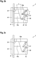
- Figs. 2a to 2c show a safety gear 1 according to the second alternative embodiment.
- the basic functionality is the same as the first
- control element 15 is not shown. Possible embodiments for a suitable actuating element 15 are in the Figures 3, 4 and 5 shown.
- Fig 2a shows the rest position of the safety gear 1.
- the guide element 12 is moved into the brake initial position by the actuating element, not shown.
- the braking element 11a is pressed against the rail 6 with a sufficiently large normal force, it moves along the guide element 12 in the direction of the braking position.
- the braking element 11a of the safety gear 1 presses so strongly on the rail 6 that the safety gear 1, together with the entire traveling body, shifts laterally until the stationary braking element 41 also touches the rail 6.
- the guide element 12 is moved up to the counter bearing stop 27 of the counter bearing 25.
- the counter bearing 25 is firmly connected to the housing 13.
- the housing 13 of the safety brake is designed in such a way that the counter bearing stop 27 and the fixed braking element 41 give way slightly under the load of the normal forces and thereby a required normal force is kept essentially constant, even if the braking elements 11a, 41 are used during the braking process or over several braking processes were rubbed off.
- the Fig. 2b shows an example of a first angle ⁇ and a second angle ⁇ .
- the force that is transmitted at the linear bearing between guide element 12 and braking element 11 acts perpendicular to the direction of the linear bearing, since the linear bearing is essentially frictionless.
- the fact that the first angle ⁇ is larger than the second angle ⁇ ensures that the force that is transmitted on the linear bearing between the guide element 12 and the brake element 11 presses on the guide element 12 at an angle, so that the force supported by the parallelogram Guide element 12 is pressed back towards the rest position.
- Fig. 3 shows a safety gear 1 according to the second alternative embodiment with a first embodiment of the adjusting element 15.
- the adjusting element acts here an operable parallelogram arm 81.
- the operable parallelogram arm 81 is extended, compared to a usual parallelogram arm 17, which is just long enough to connect the two joints.
- An electromagnet 101 is designed to hold a holding element 102.
- the holding element 102 is placed under tension via a spring 103.
- the spring 103 is therefore a tension spring.
- the power supply to the electromagnet 101 is interrupted as a trigger signal.
- the holding element 102 releases from the electromagnet 101, and the spring 103 moves the guide element 12a into the braking initial position by means of the actuable parallelogram arm 81.
- the guide element 12a is then again in contact with the counter bearing stop 27 of the counter bearing 25.
- the operable parallelogram arm 81 and the holding element 102 are also in the same position as in the original rest position.
- the electromagnet 101 therefore holds the holding element 102 again as soon as it is supplied with power again.
- Fig. 4 shows a safety gear 1 according to the second alternative embodiment with a second embodiment of the adjusting element 15.
- the electromagnet 101 is designed to hold the holding element 102.
- the holding element 102 is designed on the guide element 12.
- the guide element 12 is placed under tension via the spring 103.
- the spring 103 is therefore a tension spring.
- a spring could be attached around the electromagnet 101; such a spring would then act as a compression spring.
- the power supply to the electromagnet 101 is interrupted as a trigger signal.
- the holding element 102 releases from the electromagnet 101, and the spring 103 moves the guide element 12 into the initial braking position. In the braking position, the guide element 12 is then again in contact with the counter bearing stop 27 of the counter bearing 25. As a result, the holding element 102 is also in the same position as in the original rest position.
- the electromagnet 101 therefore holds the holding element 102 again as soon as it is supplied with power again.
- Fig. 5 shows an actuating element 15, which can be easily replaced as a modular component for a safety gear 1 if necessary.
- This actuating element 15 is particularly suitable for use in the safety gear 1 according to the first alternative embodiment as in Figs. 1a to 1c shown.
- This actuating element 15 is also suitable for use in the safety gear 1 according to the second alternative embodiment as in Figs. 2a to 2c shown.
- the electromagnet 101 is designed for this purpose Holding element 102 to hold.
- the electromagnet 101 is attached to the adjusting element 15, and the holding element 102 is movably mounted together with the adjusting mechanism 19.
- the holding element 102 could also be attached to the actuating element 15, and the electromagnet 101 could be movably mounted on the actuating element guide 104 together with the adjusting mechanism 19.
- the guide element 12 is placed under tension via the spring 103.
- the spring 103 is therefore a tension spring.
- the power supply to the electromagnet 101 is interrupted as a trigger signal.
- the holding element 102 releases from the electromagnet 101, and the spring 103 moves the adjusting mechanism 19.
- the adjusting mechanism 19 is moved back again, so that the electromagnet 101 can hold the holding element 102 as soon as it is supplied with power again.
- Fig. 6 shows an elevator 201 with a traveling body 202.
- a drive 204 to which the traveling body 202 is connected to a suspension element 203, the traveling body 202 is displaced along a travel path.
- Rails 6 are attached along the travel path.
- the traveling body is guided on the rail via guide shoes 205.
- the two safety gears 1 are designed to be able to brake the traveling body 202 on the rail 6.
Landscapes
- Engineering & Computer Science (AREA)
- Mechanical Engineering (AREA)
- Maintenance And Inspection Apparatuses For Elevators (AREA)
- Elevator Control (AREA)
- Lift-Guide Devices, And Elevator Ropes And Cables (AREA)
- Cage And Drive Apparatuses For Elevators (AREA)
Claims (15)
- Dispositif parachute (1) pour un ascenseur, comprenant- un premier élément de freinage (11a),- un premier élément de guidage (12a), et- un élément de réglage (15), dans lequelle premier élément de freinage (11a) est monté de manière à pouvoir coulisser sur le premier élément de guidage (12a) dans un palier linéaire.le premier élément de guidage (12a) peut être déplacé entre une position de repos et une position initiale de freinage,l'élément de réglage (15) est conçu pour déplacer le premier élément de guidage (12a) de la position de repos à la position initiale de freinage, en particulier pour l'activation du dispositif parachute (1), etle premier élément de freinage (11a) peut effectuer un mouvement de freinage de la position initiale de freinage à une position de freinage, et le mouvement de freinage ramène le premier élément de guidage (12a) dans la position de repos,caractérisé en ce quele premier élément de guidage (12a) est guidé sur un premier guide en parallélogramme.
- Dispositif parachute (1) selon la revendication 1, caractérisé en ce que
le premier guide en parallélogramme guide le premier élément de guidage (12a) sur un coulisseau de réglage (18). - Dispositif parachute (1) selon la revendication 2, caractérisé en ce que
un second guide en parallélogramme guide un second élément de guidage (12b) sur le coulisseau de réglage (18). - Dispositif parachute (1) selon la revendication 2 ou 3, caractérisé en ce que
l'élément de réglage (15) fait coulisser le coulisseau de réglage (18) par rapport au boîtier (13). - Dispositif parachute (1) selon l'une des revendications 2 à 4, caractérisé en ce que
le coulisseau de réglage (18) est guidé sur le boîtier (13) dans un troisième palier linéaire. - Dispositif parachute (1) selon la revendication 1, caractérisé en ce que
le premier guide en parallélogramme guide le premier élément de guidage (12a) sur un boîtier (13). - Dispositif parachute (1) selon la revendication 1, caractérisé en ce que
le premier guide en parallélogramme guide le premier élément de guidage (12a) sur le second élément de guidage (12b). - Dispositif parachute (1) selon l'une des revendications précédentes, caractérisé en ce que
l'élément de réglage (15) déplace directement le premier élément de guidage (12a). - Dispositif parachute (1) selon l'une des revendications précédentes, caractérisé en ce que, pour chaque élément de guidage (12), une butée de contre-palier (27) est réalisée sur le boîtier (13).
- Dispositif parachute (1) selon l'une des revendications précédentes, caractérisé en ce que
le guide en parallélogramme dispose d'un bras de parallélogramme (81) pouvant être actionné qui est relié à l'élément de guidage (12), et le bras de parallélogramme (81) pouvant être actionné peut être actionné directement par l'élément de réglage (15). - Dispositif parachute (1) selon l'une des revendications précédentes, caractérisé en ce que
l'élément de réglage (15) peut être activé par un signal de déclenchement électrique ou électronique. - Dispositif parachute (1) selon la revendication 10, caractérisé en ce que
l'élément de réglage (15) comprend un accumulateur d'énergie, en particulier un accumulateur d'énergie réalisé sous la forme d'un ressort (103), un élément de maintien (102) et un électroaimant (101), l'électroaimant maintient, à l'état alimenté en courant, l'élément de maintien (102) à l'encontre de la force de l'accumulateur d'énergie, et libère l'accumulateur d'énergie au moyen du signal de déclenchement électrique ou électronique, en particulier au moyen d'une coupure du flux de courant. - Dispositif parachute (1) selon l'une des revendications précédentes, caractérisé en ce quele guide en parallélogramme dispose d'un ou du bras de parallélogramme (17) qui est relié à l'élément de guidage (12), etun premier angle aigu (α) entre une direction d'extension du bras de parallélogramme (17) et une perpendiculaire à la surface de friction de la garniture de frein dans la position initiale de freinage est supérieur à un second angle aigu (β) entre la direction du palier linéaire sur l'élément de guidage (12) et une perpendiculaire à la surface de friction de la garniture de frein dans la position initiale de freinage.
- Dispositif parachute (1) selon la revendication 13, caractérisé en ce que le premier angle aigu (α) est supérieur d'au moins 10° au second angle aigu (β).
- Ascenseur comportant un corps mobile, en particulier une cabine, dans lequel le corps mobile est mobile sensiblement verticalement le long d'un trajet de déplacement entre différents étages, et des rails sont montés le long du trajet de déplacement, caractérisé en ce que
le corps mobile présente un dispositif parachute selon l'une des revendications 1 à 14 qui peut freiner le corps mobile sur les rails.
Applications Claiming Priority (2)
| Application Number | Priority Date | Filing Date | Title |
|---|---|---|---|
| EP19217111 | 2019-12-17 | ||
| PCT/EP2020/085811 WO2021122385A1 (fr) | 2019-12-17 | 2020-12-11 | Frein de sécurité pour un ascenseur |
Publications (2)
| Publication Number | Publication Date |
|---|---|
| EP4077190A1 EP4077190A1 (fr) | 2022-10-26 |
| EP4077190B1 true EP4077190B1 (fr) | 2023-11-15 |
Family
ID=68944291
Family Applications (1)
| Application Number | Title | Priority Date | Filing Date |
|---|---|---|---|
| EP20821003.9A Active EP4077190B1 (fr) | 2019-12-17 | 2020-12-11 | Dispositif d'arrêt pour un ascenseur |
Country Status (9)
| Country | Link |
|---|---|
| US (1) | US11840425B2 (fr) |
| EP (1) | EP4077190B1 (fr) |
| JP (1) | JP2023506904A (fr) |
| KR (1) | KR20220110220A (fr) |
| CN (1) | CN114829283A (fr) |
| AU (1) | AU2020405929A1 (fr) |
| BR (1) | BR112022011686A2 (fr) |
| ES (1) | ES2967052T3 (fr) |
| WO (1) | WO2021122385A1 (fr) |
Families Citing this family (2)
| Publication number | Priority date | Publication date | Assignee | Title |
|---|---|---|---|---|
| BR112022009741A2 (pt) * | 2019-11-21 | 2022-08-09 | Inventio Ag | Dispositivo de freio de segurança eletrônico facilmente reposicionável |
| CN117303157A (zh) * | 2023-11-27 | 2023-12-29 | 江苏省方正电梯有限公司 | 一种电梯防坠落装置 |
Family Cites Families (23)
| Publication number | Priority date | Publication date | Assignee | Title |
|---|---|---|---|---|
| DE19616344C2 (de) * | 1996-04-24 | 1998-11-19 | Karl Fenkl | Geregelte Fangvorrichtung für einen Aufzug |
| GB9612136D0 (en) * | 1996-06-10 | 1996-08-14 | Cameron David S | Clamping device |
| JP3532349B2 (ja) * | 1996-06-11 | 2004-05-31 | 三菱電機株式会社 | エレベータの安全装置 |
| ES2201383T3 (es) * | 1997-09-29 | 2004-03-16 | Inventio Ag | Paracaidas de freno. |
| US6293376B1 (en) * | 1999-11-22 | 2001-09-25 | Magnetar Technologies Ltd | Apparatus including eddy current braking system |
| US6425462B1 (en) * | 2000-11-03 | 2002-07-30 | Su The Tran | Gravity-assisted elevator brake/clutch |
| EP1205418B1 (fr) * | 2000-11-13 | 2010-04-21 | Cobianchi Liftteile Ag | Dispositif de freinage pour ascenseur |
| TW593117B (en) * | 2000-12-07 | 2004-06-21 | Inventio Ag | Safety brake and method for unlocking a safety brake |
| ES2357573T3 (es) | 2003-10-07 | 2011-04-27 | Otis Elevator Company | Dispositivo de parada de emergencia sin cables que se puede reiniciar de forma remota para un ascensor. |
| EP1849734B1 (fr) * | 2006-04-28 | 2009-09-09 | Inventio Ag | Dispositif de freinage pour une cabine d'ascenseur. |
| DE102006043890A1 (de) | 2006-09-19 | 2008-03-27 | Wittur Ag | Selbstrückstellmechanismus für eine Bremsfangeinrichtung Typ BSG |
| WO2009077397A1 (fr) * | 2007-12-14 | 2009-06-25 | Inventio Ag | Frein anti-collision pour deux corps d'ascenseur se déplaçant indépendamment l'un de l'autre |
| KR101997300B1 (ko) * | 2011-09-30 | 2019-10-01 | 인벤티오 아게 | 전기기계식 작동기능을 갖춘 제동 장치 |
| AU2013314563B2 (en) * | 2012-09-14 | 2016-11-17 | Inventio Ag | Actuating element for a catching device |
| CA2929420C (fr) * | 2013-11-15 | 2022-09-27 | Inventio Ag | Frein de secours pour ascenseur |
| WO2017017488A1 (fr) * | 2015-07-29 | 2017-02-02 | Otis Elevator Company | Bloc de sécurité pour ascenseur |
| GB2543291A (en) * | 2015-10-13 | 2017-04-19 | Atwell Int Ltd | Clamping device |
| US10889468B2 (en) * | 2016-12-13 | 2021-01-12 | Otis Elevator Company | Electronics safety actuator |
| US10562739B2 (en) * | 2017-08-25 | 2020-02-18 | Otis Elevator Company | Synchronized electronic safety actuator |
| US11078045B2 (en) * | 2018-05-15 | 2021-08-03 | Otis Elevator Company | Electronic safety actuator for lifting a safety wedge of an elevator |
| CN109335913B (zh) * | 2018-12-07 | 2023-12-08 | 桂林电子科技大学 | 一种电梯应急安全装置 |
| EP3674248B1 (fr) * | 2018-12-31 | 2022-09-07 | KONE Corporation | Frein de stationnement de cabine d'ascenseur |
| CN109835791A (zh) * | 2019-04-03 | 2019-06-04 | 南昌科特精密机械有限公司 | 电梯自动防坠安全钳 |
-
2020
- 2020-12-11 AU AU2020405929A patent/AU2020405929A1/en active Pending
- 2020-12-11 ES ES20821003T patent/ES2967052T3/es active Active
- 2020-12-11 JP JP2022537037A patent/JP2023506904A/ja active Pending
- 2020-12-11 US US17/757,149 patent/US11840425B2/en active Active
- 2020-12-11 BR BR112022011686A patent/BR112022011686A2/pt unknown
- 2020-12-11 CN CN202080087250.7A patent/CN114829283A/zh active Pending
- 2020-12-11 WO PCT/EP2020/085811 patent/WO2021122385A1/fr unknown
- 2020-12-11 EP EP20821003.9A patent/EP4077190B1/fr active Active
- 2020-12-11 KR KR1020227020146A patent/KR20220110220A/ko unknown
Also Published As
| Publication number | Publication date |
|---|---|
| BR112022011686A2 (pt) | 2022-09-13 |
| CN114829283A (zh) | 2022-07-29 |
| US11840425B2 (en) | 2023-12-12 |
| US20220356044A1 (en) | 2022-11-10 |
| WO2021122385A1 (fr) | 2021-06-24 |
| JP2023506904A (ja) | 2023-02-20 |
| KR20220110220A (ko) | 2022-08-05 |
| AU2020405929A1 (en) | 2022-06-30 |
| ES2967052T3 (es) | 2024-04-25 |
| EP4077190A1 (fr) | 2022-10-26 |
Similar Documents
| Publication | Publication Date | Title |
|---|---|---|
| EP3405423B1 (fr) | Dispositif de freinage pour une cabine d'un système d'ascenseur | |
| EP3068719B1 (fr) | Dispositif antichute pour ascenseur | |
| EP2925654B1 (fr) | Dispositif antichute pour un corps mobile d'une installation de levage | |
| EP1853504B9 (fr) | Dispositif de freinage ou d'arret d'une cabine d'ascenseur | |
| DE69509265T3 (de) | Vorrichtung in einem Aufzugsübergeschwindigkeitsbegrenzer | |
| EP2931641B1 (fr) | Dispositif antichute pour une installation d'ascenseur | |
| EP2978702B1 (fr) | Dispositif de freinage pour installation d'ascenseur | |
| DE3715098C2 (fr) | ||
| EP4077190B1 (fr) | Dispositif d'arrêt pour un ascenseur | |
| EP3538468B1 (fr) | Frein à câble, cabine d'ascenseur et ascenseur | |
| EP3938308B1 (fr) | Frein de sécurité et procédé de freinage | |
| DE102007015277A1 (de) | Aufzugsanlage mit einer Aufzugskabinenbremseinrichtung und Verfahren zum Bremsen einer Aufzugskabine | |
| EP2043937B1 (fr) | Dispositif de freinage ou de blocage destiné à la sécurisation temporaire d'un espace de sécurité et similaires | |
| DE102012016336A1 (de) | Geschwindigkeitsbegrenzer für ein Aufzugsystem | |
| EP4061757B1 (fr) | Parachute électronique à réarmement aisé | |
| EP1400476B1 (fr) | Parachute pour ascenseurs | |
| EP0899231B1 (fr) | Dispositif de freinage à double action | |
| EP2582606B1 (fr) | Frein d'arrêt à dispositif de blocage | |
| EP3898481A1 (fr) | Agencement de système d'ascenseur comprenant un dispositif de freinage d'ascenseur | |
| EP3037375A1 (fr) | Installation d'ascenseur dotée d'un dispositif d'arrêt et de réglage pour un système de cabine d'ascenseur | |
| EP3774629B1 (fr) | Frein à mâchoires pour une installation d'ascenseur, servant en particulier de frein de maintien et de sécurité | |
| EP3720799B1 (fr) | Dispositif d'arrêt pour cabine d'ascenseur, système d'ascenseur muni d'un dispositif d'arrêt et procédé de déverrouillage d'un dispositif d'arrêt | |
| EP4069619B1 (fr) | Dispositif de guidage et de freinage d'un corps mobile d'une installation d'ascenseur à déplacer le long d'un rail de guidage | |
| EP2931640B1 (fr) | Dispositif antichute pour une installation d'ascenseur | |
| DE202022100182U1 (de) | Auslöseeinheit zum Betätigen einer Aufzugbremsvorrichtung |
Legal Events
| Date | Code | Title | Description |
|---|---|---|---|
| STAA | Information on the status of an ep patent application or granted ep patent |
Free format text: STATUS: UNKNOWN |
|
| STAA | Information on the status of an ep patent application or granted ep patent |
Free format text: STATUS: THE INTERNATIONAL PUBLICATION HAS BEEN MADE |
|
| PUAI | Public reference made under article 153(3) epc to a published international application that has entered the european phase |
Free format text: ORIGINAL CODE: 0009012 |
|
| STAA | Information on the status of an ep patent application or granted ep patent |
Free format text: STATUS: REQUEST FOR EXAMINATION WAS MADE |
|
| 17P | Request for examination filed |
Effective date: 20220504 |
|
| AK | Designated contracting states |
Kind code of ref document: A1 Designated state(s): AL AT BE BG CH CY CZ DE DK EE ES FI FR GB GR HR HU IE IS IT LI LT LU LV MC MK MT NL NO PL PT RO RS SE SI SK SM TR |
|
| DAV | Request for validation of the european patent (deleted) | ||
| DAX | Request for extension of the european patent (deleted) | ||
| GRAP | Despatch of communication of intention to grant a patent |
Free format text: ORIGINAL CODE: EPIDOSNIGR1 |
|
| STAA | Information on the status of an ep patent application or granted ep patent |
Free format text: STATUS: GRANT OF PATENT IS INTENDED |
|
| INTG | Intention to grant announced |
Effective date: 20230719 |
|
| GRAS | Grant fee paid |
Free format text: ORIGINAL CODE: EPIDOSNIGR3 |
|
| GRAA | (expected) grant |
Free format text: ORIGINAL CODE: 0009210 |
|
| STAA | Information on the status of an ep patent application or granted ep patent |
Free format text: STATUS: THE PATENT HAS BEEN GRANTED |
|
| AK | Designated contracting states |
Kind code of ref document: B1 Designated state(s): AL AT BE BG CH CY CZ DE DK EE ES FI FR GB GR HR HU IE IS IT LI LT LU LV MC MK MT NL NO PL PT RO RS SE SI SK SM TR |
|
| REG | Reference to a national code |
Ref country code: CH Ref legal event code: EP Ref country code: GB Ref legal event code: FG4D Free format text: NOT ENGLISH |
|
| REG | Reference to a national code |
Ref country code: DE Ref legal event code: R096 Ref document number: 502020006082 Country of ref document: DE |
|
| REG | Reference to a national code |
Ref country code: IE Ref legal event code: FG4D Free format text: LANGUAGE OF EP DOCUMENT: GERMAN |
|
| PGFP | Annual fee paid to national office [announced via postgrant information from national office to epo] |
Ref country code: FR Payment date: 20231226 Year of fee payment: 4 |
|
| REG | Reference to a national code |
Ref country code: LT Ref legal event code: MG9D |
|
| REG | Reference to a national code |
Ref country code: NL Ref legal event code: MP Effective date: 20231115 |
|
| PG25 | Lapsed in a contracting state [announced via postgrant information from national office to epo] |
Ref country code: GR Free format text: LAPSE BECAUSE OF FAILURE TO SUBMIT A TRANSLATION OF THE DESCRIPTION OR TO PAY THE FEE WITHIN THE PRESCRIBED TIME-LIMIT Effective date: 20240216 |
|
| PG25 | Lapsed in a contracting state [announced via postgrant information from national office to epo] |
Ref country code: IS Free format text: LAPSE BECAUSE OF FAILURE TO SUBMIT A TRANSLATION OF THE DESCRIPTION OR TO PAY THE FEE WITHIN THE PRESCRIBED TIME-LIMIT Effective date: 20240315 |
|
| PG25 | Lapsed in a contracting state [announced via postgrant information from national office to epo] |
Ref country code: LT Free format text: LAPSE BECAUSE OF FAILURE TO SUBMIT A TRANSLATION OF THE DESCRIPTION OR TO PAY THE FEE WITHIN THE PRESCRIBED TIME-LIMIT Effective date: 20231115 |
|
| PG25 | Lapsed in a contracting state [announced via postgrant information from national office to epo] |
Ref country code: NL Free format text: LAPSE BECAUSE OF FAILURE TO SUBMIT A TRANSLATION OF THE DESCRIPTION OR TO PAY THE FEE WITHIN THE PRESCRIBED TIME-LIMIT Effective date: 20231115 |
|
| PGFP | Annual fee paid to national office [announced via postgrant information from national office to epo] |
Ref country code: ES Payment date: 20240118 Year of fee payment: 4 |
|
| REG | Reference to a national code |
Ref country code: ES Ref legal event code: FG2A Ref document number: 2967052 Country of ref document: ES Kind code of ref document: T3 Effective date: 20240425 |
|
| PG25 | Lapsed in a contracting state [announced via postgrant information from national office to epo] |
Ref country code: NL Free format text: LAPSE BECAUSE OF FAILURE TO SUBMIT A TRANSLATION OF THE DESCRIPTION OR TO PAY THE FEE WITHIN THE PRESCRIBED TIME-LIMIT Effective date: 20231115 Ref country code: LT Free format text: LAPSE BECAUSE OF FAILURE TO SUBMIT A TRANSLATION OF THE DESCRIPTION OR TO PAY THE FEE WITHIN THE PRESCRIBED TIME-LIMIT Effective date: 20231115 Ref country code: IS Free format text: LAPSE BECAUSE OF FAILURE TO SUBMIT A TRANSLATION OF THE DESCRIPTION OR TO PAY THE FEE WITHIN THE PRESCRIBED TIME-LIMIT Effective date: 20240315 Ref country code: GR Free format text: LAPSE BECAUSE OF FAILURE TO SUBMIT A TRANSLATION OF THE DESCRIPTION OR TO PAY THE FEE WITHIN THE PRESCRIBED TIME-LIMIT Effective date: 20240216 Ref country code: BG Free format text: LAPSE BECAUSE OF FAILURE TO SUBMIT A TRANSLATION OF THE DESCRIPTION OR TO PAY THE FEE WITHIN THE PRESCRIBED TIME-LIMIT Effective date: 20240215 Ref country code: PT Free format text: LAPSE BECAUSE OF FAILURE TO SUBMIT A TRANSLATION OF THE DESCRIPTION OR TO PAY THE FEE WITHIN THE PRESCRIBED TIME-LIMIT Effective date: 20240315 |
|
| PGFP | Annual fee paid to national office [announced via postgrant information from national office to epo] |
Ref country code: DE Payment date: 20231227 Year of fee payment: 4 Ref country code: CH Payment date: 20240102 Year of fee payment: 4 |