EP4069619B1 - Dispositif de guidage et de freinage d'un corps mobile d'une installation d'ascenseur à déplacer le long d'un rail de guidage - Google Patents
Dispositif de guidage et de freinage d'un corps mobile d'une installation d'ascenseur à déplacer le long d'un rail de guidage Download PDFInfo
- Publication number
- EP4069619B1 EP4069619B1 EP20812382.8A EP20812382A EP4069619B1 EP 4069619 B1 EP4069619 B1 EP 4069619B1 EP 20812382 A EP20812382 A EP 20812382A EP 4069619 B1 EP4069619 B1 EP 4069619B1
- Authority
- EP
- European Patent Office
- Prior art keywords
- braking
- guide
- holder
- guide rail
- rollers
- Prior art date
- Legal status (The legal status is an assumption and is not a legal conclusion. Google has not performed a legal analysis and makes no representation as to the accuracy of the status listed.)
- Active
Links
- 230000004913 activation Effects 0.000 claims description 29
- 238000006073 displacement reaction Methods 0.000 claims description 12
- 238000005096 rolling process Methods 0.000 claims description 10
- 230000002441 reversible effect Effects 0.000 claims description 2
- 230000008878 coupling Effects 0.000 description 4
- 238000010168 coupling process Methods 0.000 description 4
- 238000005859 coupling reaction Methods 0.000 description 4
- 230000000694 effects Effects 0.000 description 4
- 239000000725 suspension Substances 0.000 description 3
- 230000000670 limiting effect Effects 0.000 description 2
- 239000002184 metal Substances 0.000 description 2
- 229910000831 Steel Inorganic materials 0.000 description 1
- 230000003213 activating effect Effects 0.000 description 1
- 230000009286 beneficial effect Effects 0.000 description 1
- 230000000295 complement effect Effects 0.000 description 1
- 230000008094 contradictory effect Effects 0.000 description 1
- 230000001419 dependent effect Effects 0.000 description 1
- 239000013013 elastic material Substances 0.000 description 1
- 229920001971 elastomer Polymers 0.000 description 1
- 239000000806 elastomer Substances 0.000 description 1
- 238000009434 installation Methods 0.000 description 1
- 230000002427 irreversible effect Effects 0.000 description 1
- 238000004519 manufacturing process Methods 0.000 description 1
- 230000035484 reaction time Effects 0.000 description 1
- 239000012858 resilient material Substances 0.000 description 1
- 230000000284 resting effect Effects 0.000 description 1
- 239000010959 steel Substances 0.000 description 1
Images
Classifications
-
- B—PERFORMING OPERATIONS; TRANSPORTING
- B66—HOISTING; LIFTING; HAULING
- B66B—ELEVATORS; ESCALATORS OR MOVING WALKWAYS
- B66B5/00—Applications of checking, fault-correcting, or safety devices in elevators
- B66B5/02—Applications of checking, fault-correcting, or safety devices in elevators responsive to abnormal operating conditions
- B66B5/16—Braking or catch devices operating between cars, cages, or skips and fixed guide elements or surfaces in hoistway or well
- B66B5/18—Braking or catch devices operating between cars, cages, or skips and fixed guide elements or surfaces in hoistway or well and applying frictional retarding forces
-
- B—PERFORMING OPERATIONS; TRANSPORTING
- B66—HOISTING; LIFTING; HAULING
- B66B—ELEVATORS; ESCALATORS OR MOVING WALKWAYS
- B66B7/00—Other common features of elevators
- B66B7/02—Guideways; Guides
-
- B—PERFORMING OPERATIONS; TRANSPORTING
- B66—HOISTING; LIFTING; HAULING
- B66B—ELEVATORS; ESCALATORS OR MOVING WALKWAYS
- B66B7/00—Other common features of elevators
- B66B7/02—Guideways; Guides
- B66B7/04—Riding means, e.g. Shoes, Rollers, between car and guiding means, e.g. rails, ropes
Definitions
- the present invention relates to an elevator system.
- the invention relates to a device with which a moving body to be displaced on a guide rail can be guided and braked in an elevator system.
- An elevator system usually includes several moving bodies which are guided by at least one guide rail in order to prevent them from lateral, i.e. essentially horizontal, movements.
- the driving body is usually an elevator car and often at least one counterweight.
- a traveling body is generally moved vertically between different levels.
- several guide devices are usually provided on the driving body, for example in the form of guide shoes, which move along the vertical guide rail and can be supported on it in the lateral direction.
- the elevator system In order to be able to brake vertical movements of the traveling body, the elevator system generally has a braking device.
- a braking device can be designed as a so-called safety brake in order to be able to stop the vertical movement of the driving body as safely, quickly and efficiently as possible in emergency situations such as a free fall.
- the braking device can have a braking element which is pressed against the guide rail when the braking device is activated and can therefore bring about a desired braking force on the driving body coupled to the braking device due to the friction generated here.
- Guide rails in elevator systems are usually not perfectly aligned parallel to a desired travel path of a moving body, for example due to manufacturing and/or installation tolerances.
- at least locally limited portions of a guide rail can not be linear and perfectly vertical, but curved and/or obliquely aligned.
- lateral deviations in the position of a guide rail can occur, particularly in very tall elevator systems a target position of up to several millimeters. The deviations can vary along a longitudinal extent of the guide rail.
- relatively high speeds are typically required when moving the moving body, so that lateral deviations of the guide rail from its target position can lead to a rapid, jerky lateral displacement of the moving body.
- the guide devices on elevator cars of elevator systems are usually designed to be elastically mounted.
- the guide devices can yield to the deviations of the guide rail from its target position to a certain extent, at least within a predetermined tolerance range, without exerting strong and / or in particular jerky forces in the lateral direction on the elevator car.
- the design of the braking device of an elevator system must also take into account the possible lateral deviations of the guide rail from its target position.
- the braking device is usually designed in such a way that its braking element is located laterally away from the target position of the guide rail by a sufficiently dimensioned activation distance as long as the braking device is not activated.
- the activation distance is chosen so that the braking element does not come into contact with the guide rail, even with maximum expected lateral deviations of the guide rail from the target position, as long as the braking device has not been activated.
- the relatively large activation distance to be chosen in conventional braking devices means that the braking element, if the braking device is to be activated, must first be displaced over the entire activation distance until its surface comes into contact with the guide rail and a braking effect can be generated.
- an actuator that displaces the braking element must be suitably designed in order to be able to overcome such a large activation distance.
- the braking element needs to be moved over a large area Activation distance requires a certain amount of time, which can have a negative effect on the reaction time of the braking device or ultimately on the braking distance.
- WO 2004/033353 A1 a device for combining elevator guidance and safety braking is described.
- EP 3 141 511 A1 a housing arrangement for a safety actuation device is described.
- EP 1 400 476 A1 a safety gear for elevators is described.
- EP 3 141 511 A1 discloses a device according to the preamble of claim 1.
- a device for guiding and braking a moving body to be displaced along a guide rail which has a holder, a guide device and a braking device.
- the holder can be attached to the chassis. Managers can be transferred between the guide device that can be guided on the guide rail and the traveling body.
- the guide device is configured to move along at least one surface of the guide rail in the longitudinal direction of the guide rail.
- the guide device is held and mounted on the holder in such a way that the guide device can be elastically displaced relative to the holder in a direction transverse to the longitudinal direction of the guide rail by at least a predetermined tolerance distance and thereby transfers the guides to the holder.
- the braking device has a carrier and a braking element and is configured to move the braking element between a deactivated configuration in which a braking surface of the braking element is laterally spaced from the guide rail and an activated configuration in which the braking surface of the braking element can be placed against the guide rail , reversible by an activation distance in one To shift direction transverse to the guide rail.
- the carrier of the braking device is rigidly coupled to the guide device, so that the carrier of the braking device follows lateral displacements of the guide device relative to the holder.
- an elevator system which has a traveling body, a guide rail and a device according to an embodiment of the first aspect of the invention, wherein the holder of the device is attached to the traveling body and the guide device of the device is displaceably arranged to be guided along the guide rail is.
- embodiments of the device proposed here are intended, on the one hand, to make it possible to comfortably guide the running body of an elevator system along one or more guide rails during displacements in the vertical direction and to tolerate lateral deviations of the local position of the guide rail from a target position in a way can ensure that the smallest possible lateral movements, in particular no jerky lateral movements, are caused to the driving body.
- a tolerance distance within which the guide device can follow deviations of the guide rail from its target position should be relatively large.
- jerky movements of the driving body should be avoided and thus a high level of driving comfort for passengers should be achieved.
- the proposed device is intended to make it possible to brake the driving body efficiently, quickly and safely.
- a moving body can be understood to mean both an elevator car and a counterweight.
- a high level of ride comfort is particularly advantageous in elevator cabins.
- Efficient, fast and safe braking is beneficial for both elevator cars and counterweights.
- the two objectives mentioned are in some ways contradictory.
- the tolerance distance with which the guide device can follow the guide rail on local lateral deviations should be as large as possible.
- the braking devices are usually designed and arranged in such a way that their activation distance, by which their braking elements must be laterally displaced in order to produce a braking effect by resting on the guide rail, is greater than the tolerance distance of the guide device.
- the greater this activation distance the more difficult it is to move the braking elements quickly and efficiently over this activation distance in order to be able to brake the driving body.
- the activation distance can be smaller, for example by more than 10%, preferably more than 50% or even more than 80%, than the tolerance distance.
- the tolerance distance of the guide device can preferably be greater than 3 mm, more preferably greater than 4 mm or even greater than 5 mm or greater than 10 mm, whereas the activation distance of the braking device can preferably be less than 3 mm, more preferably less than 2 mm can.
- the guide device can follow lateral deviations of the guide rail along which it is supposed to run with great tolerance, but the braking device only needs to shift its braking element over a short activation distance in order to be able to quickly and efficiently trigger braking of the driving body.
- the holder, the guide device and the braking device of the proposed device should be designed and arranged in a predetermined manner and interact with one another.
- the holder should primarily be configured to be attached to the driving body and thereby fix the other components of the device to the driving body.
- the holder should be sufficiently mechanically stable to be able to accommodate managers and transfer them to the driving body. For example, leaders can appear in a range from a few Newtons to a few kilonewtons for a short time.
- Such guides can, for example, be exerted by the guide device on the holder if the guide device is, for example, suddenly displaced laterally in order to follow local position deviations of the guide rail.
- the holder can be designed as a largely rigid structure and a structure that can be rigidly attached to the driving body.
- the holder can be designed, for example, as a frame, housing or something similar.
- the holder can consist of a mechanically resilient material, in particular a metal such as steel.
- the holder can be attached essentially stationary to the driving body, for example by being fixed to the driving body using fasteners such as screws, bolts or similar.
- the guide device is configured to be moved along at least one surface of the guide rail while following the longitudinal direction of the guide rail.
- the guide device can have guide means which can roll, slide or move in some other way along the surface of the guide rail.
- the guide device and the holder cooperate in such a way that the guide device can be displaced in the lateral direction relative to the holder.
- the guide device is held and mounted on the holder in such a way that it can be moved transversely to the longitudinal direction of the guide rail relative to the holder at least over the predetermined tolerance distance.
- a mechanical coupling between the guide device on the one hand and the holder on the other hand should be designed in such a way that the relative displacement between the two components can take place elastically, that is to say without plastic and therefore irreversible deformations of those used for such a coupling Components. Furthermore, the mechanical coupling between the guide device and the holder should be designed such that the managers can be transferred from the guide device to the holder.
- the guide device can therefore be displaced along the guide rail and elastically follow any lateral deviations at least up to the predetermined tolerance distance. Forces caused in the lateral direction can be transferred elastically to the holder and thus to the driving body in order to guide them in their vertical movement on the one hand, but on the other hand to avoid causing jerky lateral movements.
- the braking device is configured, as long as it is not activated, to have no significant influence on the displacement of the driving body, but to cause braking, in particular possibly emergency braking, of the driving body when the braking device is activated.
- the braking device has at least one carrier and one braking element.
- the braking element can be displaced relative to the carrier.
- the braking element can be displaced between a deactivated configuration and an activated configuration in a direction transverse to the guide rail.
- the braking surface of the braking element is laterally spaced from the guide rail.
- a gap may be present between the braking surface of the braking element and an opposing surface of the guide rail.
- the lateral distance or the width of the gap essentially corresponds to the activation distance of the braking device.
- the activated configuration ie when the braking device is to carry out braking, the braking surface of the braking element rests on the guide rail.
- the braking element can be reversibly displaced between the deactivated and the activated configuration by moving it in the direction transverse to the guide rail by the activation distance.
- the braking surface of the braking element can be moved in a purely linear manner, for example by laterally displacing the entire braking element.
- the braking surface of the braking element can be displaced in a curved movement, for example a pivoting movement or a rotary movement be, for example, by displacing the entire braking element eccentrically about a pivot axis or axis of rotation.
- the carrier of the braking device and the guide device are rigidly coupled to one another.
- the braking device is mechanically connected to the guide device in such a way that movements of the guide device are transmitted to the carrier of the braking device to a largely equal extent.
- the braking device is mounted floating and its carrier follows lateral displacements of the guide device.
- the braking device and in particular its carrier are also held and guided in such a way that, on the one hand, they are always at a constant lateral distance is held to the guide rail and can follow deviations of the guide rail from its target position and, on the other hand, can be displaced laterally relative to the holder and thus the driving body.
- the lateral distance between the braking surface of the braking element of the braking device and the opposite surface of the guide rail, i.e. the activation distance of the braking device, can be significantly smaller than the tolerance distance by which the braking device together with the guide device can be elastically displaced laterally relative to the holder.
- the guide device has at least one roller which is rotatable about an axis and which is configured and arranged in such a way that the roller can be moved in a rolling manner with a lateral surface along the surface of the guide rail.
- the carrier of the braking device is rigidly connected to the axle of the roller.
- the guide device can be designed as a type of guide shoe, in which a roller that can be rotated about an axis is used to roll along a surface of the guide rail that serves as a guide.
- the role follows the local position of the guide rail, even if it deviates from a target position.
- the axis of the roller moves parallel to the surface of the guide rail at a constant distance that essentially corresponds to the diameter of the roller.
- the carrier of the braking device should be rigidly connected to the axis of the roller of the guide device.
- the carrier can be coupled to the axis of the roller directly or indirectly via intermediate rigid components such as a housing or a frame on which the axis of the roller is mounted, such that the axis can rotate, but essentially not can shift relative to the carrier of the braking device. Accordingly, the carrier of the braking device is held floating by the roller at a constant distance from the surface of the guide rail.
- the guide device has at least two rollers, which are each rotatable about an axis and which are configured and arranged in such a way that each of the rollers with a lateral surface is movable in a rolling manner along the surface of the guide rail and the rollers thereby move along opposite surfaces of the Guide rail can be moved in a rolling manner, the carrier of the braking device being rigidly coupled to the axis of at least one of the rollers.
- the two rollers of the guide device can thus be designed and arranged in such a way that their lateral surfaces lie opposite one another at a distance, so that the guide rail can run in a gap between the two lateral surfaces and the two rollers can be supported on the opposite surfaces of the guide rail.
- the two rollers can accommodate the guide rail between them.
- a width of the gap between the lateral surfaces of the rollers can essentially correspond to the thickness of the guide rail or at most be slightly larger than this. Accordingly, the guide device is held on the guide rail in two mutually opposite directions via the two rollers and is guided by it. Together with the rollers, the carrier of the braking device is then held at a constant distance from the guide rail in the two opposite directions.
- the guide device can have at least two rollers, which are each rotatable about an axis and which are configured and arranged in such a way that each of the rollers with a lateral surface can be moved in a rolling manner along the surface of the guide rail and the rollers along it transversely aligned surfaces of the guide rail are movable in a rolling manner, the carrier of the braking device being rigidly coupled to the axis of at least one of the rollers.
- the rollers are arranged in such a way that they cannot roll on opposite surfaces of the guide rail, but rather on surfaces of the guide rail that run transversely to one another.
- one roller can roll along a side surface and the other roller can roll along an end face of the guide rail.
- the axes of the two rollers are generally aligned parallel to one another, in this exemplary embodiment the axes of the two rollers are aligned transversely, in particular perpendicularly, to one another. With the help of the two axes designed and arranged in this way, the guide device can thus be supported on the guide rail in two mutually transverse directions.
- the guide device may be particularly preferred to equip the guide device with at least three rollers.
- Two rollers with mutually parallel axes and opposite lateral surfaces can be provided, which can be supported on opposite surfaces of the guide rail.
- a third roller can be arranged with its axis transverse to the other two axes and can be mounted in a position so that its lateral surface can roll along the end face of the guide rail connecting the opposite surfaces of the guide rail. In this way, the guide device is guided with its rollers in at least the two opposite directions and the direction transverse thereto.
- the axes of the rollers can be rigidly coupled to one another.
- the axes on the guide device can be arranged in fixed relative positions to one another.
- the axes of the different rollers can each be mounted on a component that rigidly connects them, such as a common housing or a common frame.
- the carrier of the braking device can then also be rigidly coupled to this connecting component, so that the braking device is indirectly guided in a floating manner by the rollers of the guide device at a fixed distance parallel to the guide rail.
- the guide device can be held and mounted on the holder in such a way that the guide device can be elastically displaceable relative to the holder in two mutually transverse directions and each transverse to the longitudinal direction of the guide rail by at least a predetermined tolerance distance, and thereby the managers in transferred to the holder in two directions.
- the guide device can interact with the holder in such a way that both components can be displaced relative to one another in different directions within a plane running transversely to the longitudinal direction of the guide rail. That is, on the one hand, the guide device can be displaced relative to the holder in a direction which is orthogonal to the surfaces of the guide rail, which also act as braking surfaces, and on the other hand, the guide device can also be displaced relative to the holder in a direction which is orthogonal to these surfaces connecting end face of the guide rail.
- the guide device preferably has, for example, at least three rollers in order to be guided along the guide rail in the three directions mentioned, managers can therefore be transferred between the guide device and the holder in all guided directions and yet the Allow the guide device to be displaced elastically in all three directions relative to the holder within the specified tolerance distance.
- the guide device is held and mounted on the holder via elastic elements.
- the elastic elements can be springs, for example as spiral or helical springs, one end of which cooperates with the guide device and the opposite end of which cooperates with the holder.
- the elastic elements can be formed with a sufficiently elastic material such as an elastomer and provided as a layer or layer between the guide device and the holder.
- the elastic elements can be elastically deflectable at least over the tolerance distance.
- the braking element can be wedge-shaped and the braking element has a sliding surface which can be arranged obliquely to the surface of the guide rail.
- the carrier can then have a counter-sliding surface that can be arranged at an opposite angle to the surface of the guide rail, so that the braking element can be reconfigured between the deactivated configuration and the activated configuration when moving relative to the carrier by sliding the sliding surface along the counter-sliding surface.
- the braking device can be designed with one or more wedge-shaped braking elements, similar to conventional safety brakes on driving bodies.
- a braking element has the braking surface on a side opposite the guide rail and has the sliding surface that runs obliquely on the opposite side.
- a correspondingly complementary obliquely inclined counter-sliding surface is provided on the holder.
- the wedge-shaped braking element can be displaced relative to the holder in a direction parallel to the longitudinal direction of the guide rail.
- the wedge-shaped braking element slides along the counter-sliding surface and is thereby simultaneously inserted moved in an orthogonal direction toward the guide rail until the braking surface of the braking element rests on the opposite surface of the guide rail.
- a contact pressure between the braking element and the guide rail is further increased by the fact that the braking element is carried along by the guide rail due to the friction acting between the two components and is thereby pulled further along the counter-sliding surface and is thus pressed even more strongly against the guide rail.
- the wedge-shaped braking element Before activating the braking device, the wedge-shaped braking element can always be moved parallel to the surface of the guide rail with its braking surface, for example only a few millimeters away from the surface of the guide rail, since it is always together with the carrier of the braking device due to its rigid coupling to the guide device is kept at the desired distance from the surface of the guide rail.
- This activation distance can be relatively small, for example less than 3 mm. To activate the braking device, this activation distance can then be overcome quickly and without a large displacement distance by the braking element of the braking device.
- the braking device may further comprise an electric actuator configured to displace the braking element between the deactivated configuration and the activated configuration.
- the electric actuator can, for example, have an electric motor which, with a suitable energy supply, can move the braking element from the deactivated configuration to the activated configuration and, if necessary, back again.
- the braking device can be activated using an electrical signal that is easy to transmit and/or returned to its deactivated configuration after activation.
- the displacement of the braking element can often only be carried out relatively slowly using an electric actuator, since sufficiently large actuating forces should also be applied at the same time. It is therefore advantageous for the device described here that the braking element is already deactivated Configuration can always be positioned very close to the surface of the guide rail and therefore only needs to be moved over a short activation distance.
- An alternative embodiment of the electrical actuator may contain a spring and a trigger, the trigger comprising, for example, an electromagnet that holds the spring in a tensioned position via a holding plate held by magnetic forces. By interrupting the current flow, the holding plate and thus the spring are released and the spring shifts the braking element into the activated configuration.
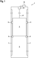
- Fig. 1 shows an elevator system 1 according to an embodiment of the present invention.
- the elevator system 1 has a traveling body 2 in the form of an elevator car 3, which can be displaced vertically within an elevator shaft 5.
- the elevator car 3 is held by support means 17, which can be displaced by a drive machine 13 controlled by a controller 15.
- the elevator car 3 can move along guide rails 7, which run vertically along walls of the elevator shaft 5.
- the drive machine 13 can be designed as a winch. Alternatively, the drive machine 13 can be designed as a traction sheave drive with a traction roller.
- the elevator system 1 includes, in addition to the traction sheave drive, a counterweight and possibly a deflection roller.
- the suspension element is extended to also hold the counterweight.
- the suspension means is guided to the elevator car 3 by the counterweight, via the drive roller and possibly via one or more deflection rollers.
- the drive roller, the counterweight, the deflection roller and the extension of the suspension element are in Fig. 1 not shown.
- the counterweight can also have a device 9.
- devices 9 for guiding and braking the elevator car 3 are attached to a floor of the elevator car 3.
- such devices 9 can also be attached to another location on the elevator car 3.
- the devices 9 are designed, similar to guide shoes, to prevent the elevator car 3 from moving laterally, i.e. horizontally, during its vertical journey through the elevator shaft 5.
- the devices 9 can optionally be supported in this task by additionally provided guide shoes 11.
- the devices 9 are intended to be able to brake the elevator car 3 in its vertical movement. In particular, the devices 9 should be able to carry out a quick and effective emergency braking of the elevator car 3.
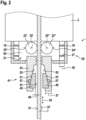
- the device 9 has a holder 19 with which the entire device 9 can be attached to the elevator car 3.
- the holder 19 is structurally designed in such a way that it can transmit managers, such as those that typically occur when the elevator car 3 is moved along the guide rails 7.
- the device 9 also has a guide device 21.
- the guide device 21 can move along at least one of two opposing surfaces 31, 33 of the guide rail 7 in the longitudinal direction 35 of the guide rail 7.
- the guide device 21 is held on the holder 19 in an elastically displaceable manner, so that the guide device 21 can be elastically displaced relative to the holder 19 in a direction 37 transverse to the longitudinal direction 35 of the guide rail 7 by at least a tolerance distance 39 of, for example, several millimeters and thereby the Executives are transferred to the holder 19.
- the device 9 also has a braking device 41.
- the braking device 41 has a carrier 43 and a braking element 45.
- the braking element 45 is arranged such that a braking surface 47 of the braking element 45 is laterally spaced from the guide rail 7. A distance between the braking surface 47 and the opposite surface 31, 33 of the guide rail 7 is referred to as the activation distance 49. In an activated configuration, however, the braking element 45 is arranged such that the braking surface 47 rests on the guide rail 7.
- the braking device 41 remains in its deactivated configuration. If the elevator car 3 is to be braked, an electric actuator 57 can move the braking element 45 along the counter-sliding surface 53 over the activation distance 49 towards the guide rail 7 shift so that its braking surface 47 rests on the opposite surface 31, 33 of the guide rail 7 and thus a braking force can be generated by friction. The distance that the brake pad 45 travels along the counter-sliding surface 53 is greater than the activation distance 49.
- the carrier 43 of the braking device 41 is rigidly coupled to the guide device 21. Accordingly, the carrier 43 follows the lateral displacements of the guide device 21 relative to the holder 19 when the guide device 21 moves along the guide rail 7 in a guided manner.
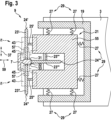
- the holder 19 is designed as a U-shaped frame in horizontal section.
- the holder 19 surrounds the guide device 21 from three sides, that is to say both on opposite sides along the horizontal direction 37 transverse to the longitudinal direction 35 of the guide rail 7 and on one side of the guide device 21, which in a further horizontal direction 59 from the Guide rail 7 faces away.
- the frame of the holder 19 is designed to be mechanically stable, for example with a thick metal sheet.
- the holder 19 is fastened to the driving body 2 so that it can withstand mechanical loads, for example using screw connections.
- the guide device 21 has a support frame 55, on which several rollers 23 are each fixed so that they can rotate about axes 25.
- the support frame 55 is again designed in a U-shape.
- Axes 25', 25" are mounted on end faces of two mutually parallel arms of this U-shaped support frame 55, so that rollers 23', 23" attached thereto can be rotated about one of the axes 25', 25" at a distance from one another in the direction 37
- a gap of predefined width results between lateral surfaces 24', 24" of these rollers 23', 23".
- the guide rail 7 extends in this gap.
- the width of the gap is dimensioned such that it corresponds to the thickness of the guide rail 7 .
- a third roller 23' is with its axis 25' in an inner region of the U-shaped Support frame 55 arranged.
- the axis 25′′′ of this roller 23′′′ extends perpendicular to the axes 25′, 25′′ of the other two rollers 23′, 23′′.
- This third roller 23′′′ is aligned and positioned in such a way that it can roll with its lateral surface 24′′′ along an end face 32 of the guide rail 7.
- the support frame 55 of the guide device 21 is coupled to the holder 19 via elastic elements 29, for example in the form of springs 27.
- the elastic elements 29 are arranged and aligned in such a way that the guide device 21 with its support frame 55 can be elastically displaced relative to the holder 19 both in the horizontal direction 37 and in the horizontal direction 59 perpendicular thereto, at least within the tolerance distance 39 .
- the support frame 55 of the guide device 21 can thus be displaced in all directions within a horizontal plane by at least the tolerance distance 39, so that rollers 23 attached to it always run even in the event that the guide rail 7 does not always run locally at its target position, but deviates from it can roll along the surfaces 31, 32, 33 of the guide rails 7.
- the braking device 41 is rigidly connected with its carrier 43 to the carrier frame 55 of the guide device 21 in the example shown.
- the braking element 45 of the braking device 41 is thus floating and is always carried along with the movement of the guide device 21 and is always at a predetermined lateral distance from the surfaces 31, 32, 33 of the respectively assigned guide rail 7. This lateral distance can be equal to or smaller than that Be activation distance 49, over which the braking element 45 must be displaced in order to rest against an opposite surface 31, 32, 33 in the activated configuration of the braking device 41 and thereby produce a desired braking effect.
- the braking device 41 is equipped with two wedge-shaped braking elements 45.
- Each wedge-shaped braking element 45 has, on a side opposite the braking surface 47, a sliding surface 51 which runs obliquely to the surface 31, 33 of the guide rail 7 to which it lies.
- the braking element 45 can be moved from the deactivated configuration to the activated configuration using the electrical actuator 57 (shown only schematically).
- the carrier 43 can have a bearing rail which includes the counter-sliding surface 53 and which can be folded away from the rest of the carrier 43, as shown in FIG WO 2015 071188 is shown.
- the bearing rail is articulated at one of its ends to the rest of the carrier 43, so that the movement in the joint leads to a movement of the bearing rail in the direction 37.
- the electric actuator 57 can move the bearing rail laterally, ie in the direction 37 transverse to the longitudinal direction 35 of the guide rail 7, towards the guide rail 7.
- the actuator 57 can move the braking element towards the guide rail 7 by briefly lifting the sliding surface 51 from the counter-sliding surface 53.
- the braking element 45 can have a groove which opens the braking element 45 towards the actuator 57.
- the actuator 57 presses in the lateral direction on the bottom of the groove in the braking element 45.
- the groove is designed in such a way that it creates the required space in the braking element 45, so that the braking element 45 remains movable along the longitudinal direction 35 when the electric actuator 57 in an extended state at least partially protrudes into the braking element.
- the actuator 57 can displace the braking element 45 in the longitudinal direction 35 of the guide rail 7, with its sliding surface 51 sliding along the counter-sliding surface 53 of the carrier 43 and thus also being moved laterally towards the guide rail 7.
- the device 9 described here for guiding and braking the moving body 2 offers the possibility of using the elevator car 3 comfortably on the one hand to guide the guide device 21, which can be moved elastically over the tolerance distance, during its vertical displacement along the guide rail 7.
- the braking device 41 of the device 9 with its braking element 45 or its braking elements 45 can be moved past the guide rail 7 with very little lateral play in the deactivated configuration, since the braking device 41 is rigidly coupled to the guide device 21. Accordingly, the braking device 41 can be activated quickly and effectively by engaging the braking element 45 or the braking elements 45 towards the guide rail 7 over an activation distance 49 that is smaller than the tolerance distance 39.
Landscapes
- Engineering & Computer Science (AREA)
- Mechanical Engineering (AREA)
- Types And Forms Of Lifts (AREA)
- Maintenance And Inspection Apparatuses For Elevators (AREA)
Claims (13)
- Dispositif (9) de guidage et de freinage d'un corps mobile (2) à déplacer le long d'un rail de guidage (7), présentant :une fixation (19),un moyen de guidage (21), etun moyen de freinage (41),dans lequel la fixation (19) peut être fixée sur le corps mobile (2) et des forces de guidage peuvent être transférées entre le moyen de guidage (21) pouvant être guidé sur le rail de guidage (7) et le corps mobile (2),dans lequel le moyen de guidage (21) est mobile le long d'au moins une surface (31, 32, 33) du rail de guidage (7) dans la direction longitudinale (35) du rail de guidage (7), dans lequel le moyen de freinage (41) présente un support (43) et un élément de freinage (45) et est configuré pour déplacer l'élément de freinage (45) entre une configuration désactivée, dans laquelle une surface de freinage (47) de l'élément de freinage (45) peut être espacée latéralement du rail de guidage (7), et une configuration activée, dans laquelle la surface de freinage (47) de l'élément de freinage (45) peut être appliquée sur le rail de guidage (7), de manière réversible sur une distance d'activation (49) dans une direction (37) transversale au rail de guidage (7),dans lequel le support (43) du moyen de freinage (41) est accouplé rigidement au moyen de guidage (21) de telle sorte que le support (43) du moyen de freinage (41) suit des déplacements latéraux du moyen de guidage (21) par rapport à la fixation (19),caractérisé en ce que le moyen de guidage (21) est maintenu et monté sur la fixation (19) de sorte que le moyen de guidage (21) peut être déplacé élastiquement par rapport à la fixation (19) dans une direction (37, 59) transversale à la direction longitudinale (35) du rail de guidage (7), sur au moins une distance de tolérance (39) prédéterminée, et transfère ainsi les forces de guidage à la fixation (19).
- Dispositif selon la revendication 1, dans lequel le moyen de guidage (21) présente au moins un rouleau (23), lequel est rotatif autour d'un axe (25) et est configuré et disposé de telle sorte que le rouleau (23), comportant une surface d'enveloppe (24), peut être déplacé par roulement le long de la surface (31, 32, 33) du rail de guidage (7), dans lequel le support (43) du moyen de freinage (41) est rigidement relié à l'axe (25) du rouleau (23).
- Dispositif selon l'une des revendications précédentes, dans lequel le moyen de guidage (21) présente au moins deux rouleaux (23', 23"), lesquels sont respectivement rotatifs autour d'un axe (25', 25") et sont configurés et disposés de telle sorte que chacun des rouleaux (23', 23"), comportant une surface d'enveloppe (24', 24"), peut être déplacé par roulement le long des surfaces (31, 33) du rail de guidage (7) et les rouleaux (23', 23") peuvent ainsi être déplacés par roulement le long de surfaces (31, 33) opposées du rail de guidage (7), dans lequel le support (43) du moyen de freinage (41) est rigidement accouplé à l'axe (25', 25") d'au moins l'un des rouleaux (23', 23").
- Dispositif selon l'une des revendications précédentes, dans lequel le moyen de guidage (21) présente au moins deux rouleaux (23', 23‴), lesquels sont respectivement rotatifs autour d'un axe (25', 25‴) et sont configurés et disposés de telle sorte que chacun des rouleaux (23', 23‴), comportant une surface d'enveloppe (24', 24‴), peut être déplacé par roulement le long des surfaces (31, 32) du rail de guidage (7) et les rouleaux (23', 23‴) peuvent ainsi être déplacés par roulement le long de surfaces (31, 32) alignées transversalement l'une avec l'autre du rail de guidage (7), dans lequel le support (43) du moyen de freinage (41) est rigidement accouplé à l'axe (25', 25‴) d'au moins l'un des rouleaux (23', 23‴).
- Dispositif selon l'une des revendications 3 et 4, dans lequel les axes (25) des rouleaux (23) sont accouplés rigidement entre eux.
- Dispositif selon l'une des revendications précédentes, dans lequel le moyen de guidage (21) est maintenu et monté sur la fixation (19) de telle sorte que le moyen de guidage (21) peut être déplacé élastiquement par rapport à la fixation (19) dans deux directions (37, 59) transversales l'une par rapport à l'autre et transversales chacune par rapport à la direction longitudinale (35) du rail de guidage (7), respectivement d'au moins une distance de tolérance (39) prédéterminée, et transfère ainsi les forces de guidage dans les deux directions (37, 59) à la fixation (19).
- Dispositif selon l'une des revendications précédentes, dans lequel le moyen de guidage (21) est maintenu et monté sur la fixation (19) par l'intermédiaire d'éléments (29) élastiques.
- Dispositif selon l'une des revendications précédentes, dans lequel l'élément de freinage (45) est cunéiforme, l'élément de freinage (51) présente une surface de glissement (51) pouvant être disposée de manière à s'étendre obliquement par rapport à la surface (31, 33) du rail de guidage (7) et dans lequel le support (43) présente une surface de contre-glissement (53) pouvant être disposée de manière à s'étendre obliquement par rapport à la surface (31, 33) du rail de guidage (7), de telle sorte que l'élément de freinage (45), lorsqu'il se déplace par rapport au support (43) par glissement de la surface de glissement (51) le long de la surface de contre-glissement (53), peut être reconfiguré entre la configuration désactivée et la configuration activée.
- Dispositif selon l'une des revendications précédentes, dans lequel le moyen de freinage (41) présente en outre un actionneur (57) électrique configuré pour déplacer l'élément de freinage (45) entre la configuration désactivée et la configuration activée.
- Dispositif selon l'une des revendications précédentes, dans lequel la distance d'activation (49) est inférieure à la distance de tolérance (39).
- Dispositif selon l'une des revendications précédentes, dans lequel la distance de tolérance (39) est supérieure à 3 mm.
- Dispositif selon l'une des revendications précédentes, dans lequel la distance d'activation (49) est inférieure à 3 mm.
- Installation d'ascenseur (1), présentant :un corps mobile (2),un rail de guidage (7) etun dispositif (9) selon l'une des revendications précédentes,dans laquelle la fixation (19) du dispositif (9) est fixée sur le corps mobile (2) et le moyen de guidage (21) du dispositif (9) est disposé de façon à pouvoir être déplacé de manière guidée le long du rail de guidage (7).
Applications Claiming Priority (2)
| Application Number | Priority Date | Filing Date | Title |
|---|---|---|---|
| EP19212903.9A EP3831759A1 (fr) | 2019-12-02 | 2019-12-02 | Dispositif de guidage et de freinage d'un corps mobile d'une installation d'ascenseur à déplacer le long d'un rail de guidage |
| PCT/EP2020/084231 WO2021110726A1 (fr) | 2019-12-02 | 2020-12-02 | Appareil de guidage et de freinage d'un corps mobile d'un système de levage, ledit corps devant être déplacé le long d'une voie de guidage |
Publications (2)
| Publication Number | Publication Date |
|---|---|
| EP4069619A1 EP4069619A1 (fr) | 2022-10-12 |
| EP4069619B1 true EP4069619B1 (fr) | 2023-10-04 |
Family
ID=68762629
Family Applications (2)
| Application Number | Title | Priority Date | Filing Date |
|---|---|---|---|
| EP19212903.9A Withdrawn EP3831759A1 (fr) | 2019-12-02 | 2019-12-02 | Dispositif de guidage et de freinage d'un corps mobile d'une installation d'ascenseur à déplacer le long d'un rail de guidage |
| EP20812382.8A Active EP4069619B1 (fr) | 2019-12-02 | 2020-12-02 | Dispositif de guidage et de freinage d'un corps mobile d'une installation d'ascenseur à déplacer le long d'un rail de guidage |
Family Applications Before (1)
| Application Number | Title | Priority Date | Filing Date |
|---|---|---|---|
| EP19212903.9A Withdrawn EP3831759A1 (fr) | 2019-12-02 | 2019-12-02 | Dispositif de guidage et de freinage d'un corps mobile d'une installation d'ascenseur à déplacer le long d'un rail de guidage |
Country Status (6)
| Country | Link |
|---|---|
| US (1) | US20230049908A1 (fr) |
| EP (2) | EP3831759A1 (fr) |
| KR (1) | KR20220101114A (fr) |
| CN (1) | CN114787063A (fr) |
| AU (1) | AU2020396188A1 (fr) |
| WO (1) | WO2021110726A1 (fr) |
Family Cites Families (21)
| Publication number | Priority date | Publication date | Assignee | Title |
|---|---|---|---|---|
| US1581459A (en) * | 1924-07-11 | 1926-04-20 | Otis Elevator Co | Elevator safety appliance |
| FI85129C (fi) * | 1989-12-14 | 1992-03-10 | Kone Oy | Faongapparat. |
| FI84253C (fi) * | 1989-12-18 | 1991-11-11 | Kone Oy | Faongsapparat foer en hiss. |
| JP3381350B2 (ja) * | 1993-02-03 | 2003-02-24 | 株式会社日立製作所 | エレベータ用非常止め装置およびエレベータ |
| FI105091B (fi) * | 1997-01-30 | 2000-06-15 | Kone Corp | Johdejarru |
| JPH11199159A (ja) * | 1997-11-06 | 1999-07-27 | Otis Elevator Co | エレベータ安全制動機 |
| KR200278377Y1 (ko) * | 2002-02-22 | 2002-06-20 | 정인숙 | 엘리베이터 비상정지장치 |
| EP1400476B1 (fr) | 2002-09-23 | 2009-10-21 | Inventio Ag | Parachute pour ascenseurs |
| CN100457593C (zh) | 2002-10-09 | 2009-02-04 | 奥蒂斯电梯公司 | 组合式提升机引导和安全制动装置及提升机系统 |
| AU2003300127A1 (en) * | 2003-12-31 | 2005-08-03 | Otis Elevator Company | Elevator safety device |
| EP1783086B1 (fr) * | 2005-11-08 | 2014-03-19 | Dynatech, Dynamics & Technology, S. L. | Dispositif de sécurité bidirectionnel progressif |
| FI118124B (fi) * | 2006-01-17 | 2007-07-13 | Kone Corp | Johdejarru |
| ATE504532T1 (de) * | 2006-11-08 | 2011-04-15 | Otis Elevator Co | Aufzugbremsvorrichtung |
| MY143851A (en) * | 2006-12-05 | 2011-07-15 | Inventio Ag | Braking device for holding and braking a lift cabin in a lift facility |
| EP2760777B1 (fr) * | 2011-09-30 | 2015-06-17 | Inventio AG | Dispositif de freinage doté d'un dispositif d'actionnement électromécanique |
| AU2013351430B2 (en) * | 2012-11-27 | 2016-12-22 | Inventio Ag | Catching device for a traveling body of an elevator system |
| CN103010900A (zh) * | 2012-12-19 | 2013-04-03 | 北京升华电梯有限公司 | 直行电梯轮式导靴 |
| NZ719226A (en) | 2013-11-15 | 2021-07-30 | Inventio Ag | Safety brake for an elevator |
| ES2715549T3 (es) * | 2015-09-08 | 2019-06-04 | Otis Elevator Co | Conjunto de alojamiento para un dispositivo de actuación de seguridad |
| US10889468B2 (en) * | 2016-12-13 | 2021-01-12 | Otis Elevator Company | Electronics safety actuator |
| CN108285081B (zh) * | 2017-01-10 | 2021-08-03 | 奥的斯电梯公司 | 升降机轿厢的稳定装置及其控制方法、升降机系统 |
-
2019
- 2019-12-02 EP EP19212903.9A patent/EP3831759A1/fr not_active Withdrawn
-
2020
- 2020-12-02 KR KR1020227018126A patent/KR20220101114A/ko unknown
- 2020-12-02 US US17/756,483 patent/US20230049908A1/en active Pending
- 2020-12-02 AU AU2020396188A patent/AU2020396188A1/en active Pending
- 2020-12-02 WO PCT/EP2020/084231 patent/WO2021110726A1/fr unknown
- 2020-12-02 EP EP20812382.8A patent/EP4069619B1/fr active Active
- 2020-12-02 CN CN202080084458.3A patent/CN114787063A/zh active Pending
Also Published As
| Publication number | Publication date |
|---|---|
| EP3831759A1 (fr) | 2021-06-09 |
| CN114787063A (zh) | 2022-07-22 |
| WO2021110726A1 (fr) | 2021-06-10 |
| EP4069619A1 (fr) | 2022-10-12 |
| AU2020396188A1 (en) | 2022-06-23 |
| US20230049908A1 (en) | 2023-02-16 |
| KR20220101114A (ko) | 2022-07-19 |
Similar Documents
| Publication | Publication Date | Title |
|---|---|---|
| EP2760776B1 (fr) | Système de freinage à actionnement électromécanique | |
| EP2925654B1 (fr) | Dispositif antichute pour un corps mobile d'une installation de levage | |
| EP2760777B1 (fr) | Dispositif de freinage doté d'un dispositif d'actionnement électromécanique | |
| EP2547617B1 (fr) | Installation d'ascenseur équipée d'un dispositif de frein et d'un actionneur | |
| AT501415B1 (de) | Brems- bzw. fangeinrichtung für eine aufzugskabine | |
| EP1930280A1 (fr) | Dispositif de freinage et rail de guidage d'un ascenseur avec surface de freinage trapézoïdale | |
| EP2651809A1 (fr) | Actionnement d'un parachute | |
| WO2015144686A1 (fr) | Dispositif de freinage d'une cabine d'une installation d'ascenseur | |
| EP2855327B1 (fr) | Unité d'amortissement pour ascenseur | |
| EP3938308B1 (fr) | Frein de sécurité et procédé de freinage | |
| EP4077190B1 (fr) | Dispositif d'arrêt pour un ascenseur | |
| EP2582606B1 (fr) | Frein d'arrêt à dispositif de blocage | |
| WO2008011896A1 (fr) | Dispositif de freinage ou de blocage destiné à la sécurisation temporaire d'un espace de sécurité et similaires | |
| EP4069619B1 (fr) | Dispositif de guidage et de freinage d'un corps mobile d'une installation d'ascenseur à déplacer le long d'un rail de guidage | |
| EP2855328B1 (fr) | Unité d'amortissement pour ascenseur | |
| EP3554981B1 (fr) | Frein de stationnement | |
| EP4072988B1 (fr) | Dispositif de freinage, par exemple pourvu d'élément de freinage cunéiforme, permettant de freiner un corps de roulement pouvant être déplacé par guidage le long d'un rail de guidage dans un dispositif de déplacement | |
| EP3774629B1 (fr) | Frein à mâchoires pour une installation d'ascenseur, servant en particulier de frein de maintien et de sécurité | |
| EP4038002A1 (fr) | Dispositif de frein | |
| WO1985002169A1 (fr) | Dispositif parachute notamment pour cabines d'ascenseur | |
| EP1930281B1 (fr) | Dispositif de freinage et rail de guidage d'un ascenseur avec surface de freinage trapézoïdale | |
| CH568870A5 (en) | Brake system for ski lifts and cableways - has wedge shaped needle bearing mounted emergency brake | |
| WO2020160744A1 (fr) | Système d'ascenseur |
Legal Events
| Date | Code | Title | Description |
|---|---|---|---|
| STAA | Information on the status of an ep patent application or granted ep patent |
Free format text: STATUS: UNKNOWN |
|
| STAA | Information on the status of an ep patent application or granted ep patent |
Free format text: STATUS: THE INTERNATIONAL PUBLICATION HAS BEEN MADE |
|
| PUAI | Public reference made under article 153(3) epc to a published international application that has entered the european phase |
Free format text: ORIGINAL CODE: 0009012 |
|
| STAA | Information on the status of an ep patent application or granted ep patent |
Free format text: STATUS: REQUEST FOR EXAMINATION WAS MADE |
|
| 17P | Request for examination filed |
Effective date: 20220504 |
|
| AK | Designated contracting states |
Kind code of ref document: A1 Designated state(s): AL AT BE BG CH CY CZ DE DK EE ES FI FR GB GR HR HU IE IS IT LI LT LU LV MC MK MT NL NO PL PT RO RS SE SI SK SM TR |
|
| DAV | Request for validation of the european patent (deleted) | ||
| DAX | Request for extension of the european patent (deleted) | ||
| GRAP | Despatch of communication of intention to grant a patent |
Free format text: ORIGINAL CODE: EPIDOSNIGR1 |
|
| STAA | Information on the status of an ep patent application or granted ep patent |
Free format text: STATUS: GRANT OF PATENT IS INTENDED |
|
| INTG | Intention to grant announced |
Effective date: 20230612 |
|
| GRAS | Grant fee paid |
Free format text: ORIGINAL CODE: EPIDOSNIGR3 |
|
| GRAA | (expected) grant |
Free format text: ORIGINAL CODE: 0009210 |
|
| STAA | Information on the status of an ep patent application or granted ep patent |
Free format text: STATUS: THE PATENT HAS BEEN GRANTED |
|
| AK | Designated contracting states |
Kind code of ref document: B1 Designated state(s): AL AT BE BG CH CY CZ DE DK EE ES FI FR GB GR HR HU IE IS IT LI LT LU LV MC MK MT NL NO PL PT RO RS SE SI SK SM TR |
|
| REG | Reference to a national code |
Ref country code: GB Ref legal event code: FG4D Free format text: NOT ENGLISH |
|
| REG | Reference to a national code |
Ref country code: CH Ref legal event code: EP |
|
| REG | Reference to a national code |
Ref country code: IE Ref legal event code: FG4D Free format text: LANGUAGE OF EP DOCUMENT: GERMAN |
|
| REG | Reference to a national code |
Ref country code: DE Ref legal event code: R096 Ref document number: 502020005558 Country of ref document: DE |
|
| REG | Reference to a national code |
Ref country code: LT Ref legal event code: MG9D |
|
| PGFP | Annual fee paid to national office [announced via postgrant information from national office to epo] |
Ref country code: FR Payment date: 20231226 Year of fee payment: 4 |
|
| REG | Reference to a national code |
Ref country code: NL Ref legal event code: MP Effective date: 20231004 |
|
| PG25 | Lapsed in a contracting state [announced via postgrant information from national office to epo] |
Ref country code: NL Free format text: LAPSE BECAUSE OF FAILURE TO SUBMIT A TRANSLATION OF THE DESCRIPTION OR TO PAY THE FEE WITHIN THE PRESCRIBED TIME-LIMIT Effective date: 20231004 |
|
| PG25 | Lapsed in a contracting state [announced via postgrant information from national office to epo] |
Ref country code: GR Free format text: LAPSE BECAUSE OF FAILURE TO SUBMIT A TRANSLATION OF THE DESCRIPTION OR TO PAY THE FEE WITHIN THE PRESCRIBED TIME-LIMIT Effective date: 20240105 |
|
| PG25 | Lapsed in a contracting state [announced via postgrant information from national office to epo] |
Ref country code: IS Free format text: LAPSE BECAUSE OF FAILURE TO SUBMIT A TRANSLATION OF THE DESCRIPTION OR TO PAY THE FEE WITHIN THE PRESCRIBED TIME-LIMIT Effective date: 20240204 |
|
| PG25 | Lapsed in a contracting state [announced via postgrant information from national office to epo] |
Ref country code: LT Free format text: LAPSE BECAUSE OF FAILURE TO SUBMIT A TRANSLATION OF THE DESCRIPTION OR TO PAY THE FEE WITHIN THE PRESCRIBED TIME-LIMIT Effective date: 20231004 |