EP1982945A1 - Braking or arresting device with a roller partly running on a bronze coating and an inclined friction surface - Google Patents
Braking or arresting device with a roller partly running on a bronze coating and an inclined friction surface Download PDFInfo
- Publication number
- EP1982945A1 EP1982945A1 EP07007905A EP07007905A EP1982945A1 EP 1982945 A1 EP1982945 A1 EP 1982945A1 EP 07007905 A EP07007905 A EP 07007905A EP 07007905 A EP07007905 A EP 07007905A EP 1982945 A1 EP1982945 A1 EP 1982945A1
- Authority
- EP
- European Patent Office
- Prior art keywords
- braking
- roller
- pressure body
- catching device
- guide rail
- Prior art date
- Legal status (The legal status is an assumption and is not a legal conclusion. Google has not performed a legal analysis and makes no representation as to the accuracy of the status listed.)
- Granted
Links
Images


Classifications
-
- B—PERFORMING OPERATIONS; TRANSPORTING
- B66—HOISTING; LIFTING; HAULING
- B66B—ELEVATORS; ESCALATORS OR MOVING WALKWAYS
- B66B5/00—Applications of checking, fault-correcting, or safety devices in elevators
- B66B5/02—Applications of checking, fault-correcting, or safety devices in elevators responsive to abnormal operating conditions
- B66B5/16—Braking or catch devices operating between cars, cages, or skips and fixed guide elements or surfaces in hoistway or well
- B66B5/18—Braking or catch devices operating between cars, cages, or skips and fixed guide elements or surfaces in hoistway or well and applying frictional retarding forces
- B66B5/22—Braking or catch devices operating between cars, cages, or skips and fixed guide elements or surfaces in hoistway or well and applying frictional retarding forces by means of linearly-movable wedges
Definitions
- the invention relates to a braking or catching device for an elevator car, which is stirred in a shaft along vertical guide rails.
- the braking or catching device uses a provided with a friction roller as a brake body. Once activated, this role is drawn into a gap. In this case, the friction generating pressure is always greater, the further the role is drawn into the gap in the direction of its final position.
- Elevator car or car is used here and in the following as a collective term and includes both conventional combinations of cabins or load carriers or platforms of all kinds, which are supported by a car frame, as well as car frame-less constructions.
- Braking or catching devices on elevators serve to lift an elevator car in the event of an uncontrolled driving condition or an impermissibly high driving speed, such as they z. B. in case of malfunction of the controller or a drive or its brake and a rope break may occur, decelerate.
- a corresponding brake catch device is known, for example, from the European patent application EP 0 841 280 A1 known.
- the proposed by said patent application brake catcher is of modern design, it comes with only a few components. Unlike the older brake catcher devices from the prior art, it requires no additional screw or disc springs to specify a defined course of the braking force up to the cabin catch. Instead, the intended for mounting on the elevator car and the brake roller overlapping housing of the brake catcher (hereinafter: the pressure body) is designed here so that it exerts itself a defined spring action.
- the pressure body with activated brake on the one hand possibly with the interposition of a friction lining presses directly on the guide rail and presses on the other side indirectly via the brake roller on the guide rail.
- the current braking forces are correspondingly higher.
- This spring effect together with the corresponding layout of the groove or gap, where the brake roller runs under high friction, to the fact that sets the desired, defined braking effect.
- a major advantage of this known brake catcher is in particular that its special design already largely counteracts home misalignment between the guide rail and the braking surface. Therefore, the use causes d. H. the activation of this brake catcher, only a slight wear on the guide rail. The brake catcher itself is only subject to low wear.
- the tribological conditions are overall (and thus the entire sliding behavior, including that in the steel pairing) significantly improved by the fact that the gap is provided on the side of the pressure hull in the region of its end position locally with a fitting of bearing material, which is designed and arranged in that, in its final position, the roller partly slides on the bearing material and partly on the i. d. R. harder material of the rest of the sliding surface providing pressure hull.
- This remaining sliding surface need not necessarily be an integral part of the pressure hull. Instead, it may also be another fitting that is attached to the pressure body.
- a fitting advantageously (but not necessarily) means a separate, attached to the pressure body component. Rather, in principle, sprues or otherwise thick coatings are covered. However, the best results can be achieved by means of a component that is fastened separately and / or permanently to the pressure body and serves as a fitting. This is because the easiest way to provide for a bearing made of bearing material, which has the required thickness and abrasion resistance in said manner.
- the fitting consists of a non-ferrous metal.
- Non-ferrous metals have the required tribological properties.
- a non-ferrous metal is selected that can withstand high pressures.
- Such a non-ferrous metal is for example bearing bronze.
- the pressure body (or the additional fitting on which the roller next to the lining of bearing material glides) is made of tempered steel, instead of spring steel. This brings significant advantages in the machining of the pressure hull, because spring steel can only be machined extremely bad.
- the role carries by their sliding on the bearing material or the fitting of bearing material intended from bearing material and drags the worn bearing material in the area in which the roller slides on the pressure body, d. H.
- the steel surface is provided with non-ferrous metal particles.
- a profiling in particular a profiling in the form of a knurl.
- the purpose of such a profiling is to influence the friction conditions in such a way that it is always ensured that the roll substantially rolls both on the guide rail and on the pressure body in the phase in which it is progressively drawn deeper into the gap. and does not slide appreciably.
- the role reliably reaches its final position.
- said profiling ensures that the roll still rolls on the guide rail when it has reached its final position. This is the only way to ensure that the effect according to the invention occurs.
- the knurl is designed so that between the guide rail and the role actually to real stiction or a combination of static friction and possibly positive fit in the area of the knurling tips, so that the roll rolls completely on the guide rail.
- the fitting consists of a bolt of a suitable bearing material, which is rotationally held in a corresponding receiving bore of the pressure hull.
- both the bolt and the receiving bore assigned to it are milled or ground over, at least in the region in which the roller slides as intended on the bolt. This is done by first inserting the bolt into the bore, even before the contour has been milled or ground, which determines the contact between the pressure body and its fitting from the bearing material determined in the role. The milling or grinding process takes place afterwards. In this way, the fitting of the bearing material can be easily and very firmly connected to the pressure hull. Under a bolt is preferably understood round material.
- a four-, six- or multi-bolt is conceivable in principle, but de praxi actually rather a Theoretikum, as in the pressure body much easier a corresponding round recording for the bolt can be incorporated, as a four- or more-edged.
- the stop that limits the path that the roller is pulled into the gap and thus each defines an end position for the role, designed so that the material removal at the fitting of the bearing material is at least partially compensated by the fact that the role can be pulled further into the gap between the pressure hull and the guide rail, when the fitting of the bearing material is noticeably worn.
- the groove used in said embodiment is designed such that the friction surface or knurl of the roll in the end position still has the corresponding clearance with respect to the pressure body. if the fitting is a little worn and thereby provides over the shoulders of the role of an end position for the role, which no longer corresponds to their original end position.
- the gap-forming portion of the pressure body has a groove for receiving the provided for contact with the guide rail friction surface of the roller.
- the groove is designed so that when the roller is in its final position, play between the friction surface (the largest circumference) of the roller and the groove, so that the friction surface has no or no significant contact with the pressure body and its fitting and the role pressure body side, at least substantially only by the sliding friction between the i. d. R. smooth shoulders and the pressure body and the fitting is braked.
- the inclined surface can be both the counter-pressure surface (preferred) and the surface on the roller that comes into contact with the guide rail as intended.
- the key advantage of the invention is that the pressure and the static or sliding friction forces, and the heat generated thereby, spread over a larger area, especially in the phase of maximum delay and load, which increases the risk of localized flow, burning or Welding and wear of the friction surfaces and damage to the corresponding surfaces of the guide rails significantly reduced.
- the mobility required for the alignment of the inclined surface is produced by the fact that the inclined surface moves in the course of the elastic expansion of the base body together with the corresponding leg of the body relative to the associated functional surface of the guide rail. This is achieved by not only moving towards the guide rail, but also performing a rotational movement relative to the guide rail in the resultant.
- no plate or coil springs are installed in the brake or catching device according to the invention. Because such springs are not only a cost factor, but are also a potential source of error - especially in coil springs spring breaks are never completely ruled out, especially when coupled to packages disc springs sliding and static friction influences occur during compression, which under unfavorable circumstances noticeable irregularities or deviations can occur in the reproducibility.
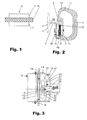
- Fig. 2 how out Fig. 2 can be seen, the guide rails 2 a connected via a web 6 with a rail foot 7 rail head 8, which the active surfaces of the guide rail forms, with which the braking or catching device according to the invention interacts after activation.
- a braking member in the form of a roller 9 is provided, which is close to its two lateral end faces (see Fig. 1 ) is provided with shoulders 11.
- the outermost lateral surface of the roller 9 serves as a friction surface 12.
- it is provided with a knurling or with a different profiling. The latter serves to reliably pull the roller (9) into the gap or roll it in until the roller (9) reaches its end position.
- the knurl also ensures that in the end position of the role at least no significant sliding between the roller (9) and the guide rail (2) occurs, but rolls the role on the guide rail.
- the Fig. 2 shows a braking or catching device 14 according to the invention in a horizontal section.
- the braking or catching device has a pressure body 19, which essentially corresponds to a U-profile, but u. U. could also have the cross section of a slotted circular or elliptical profile. Decisive is that the two legs 16, 17 in the region of their free ends, the guide rail 2 include.
- the pressure body 19 on its leg 16 on a gap-forming portion 20a which together with the corresponding guide rail forms a gap 20 in intended mounted braking device 14, in which the roller 9 is guided.
- the gap-forming portion 20a has a groove 21, which receives the friction surface 12 (see Fig.
- the pressure hull consists of a suitable tempering steel, as it is used for the production of screw and disc springs. Which tempering steels have hitherto been used for screw and disc springs is known to the person skilled in the art.
- the inventively necessary spring action is achieved by suitable design of the base body 19 as a U-profile or the like. Unlike spring steel, such tempered steel can be machined very easily.
- the roller 9 is rotatable on a z.
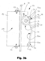
- axis 22 which, as of Fig. 3 illustrated, an opening 23 in the leg 16 (or in an attachment of the leg in the form of a holding plate 18) passes through and is held in a holder 25.
- the gap 20 is essentially limited on the one hand by the guide rail and on the other hand by the gap-forming portion 20a of the pressure hull.
- the contour of the gap-forming portion 20a corresponds to one of Fig. 8 shown contours. Each of these selectable contours corresponds to a specific response characteristic and a maximum achievable braking friction.
- a preferably V-shaped contoured locking surface 31 is provided between the up-driving and down-driving portions of the gap-forming portion in the embodiments of FIG Fig. 3b and 7 .
- This is designed so that the roller 9 (despite the inevitable friction influences) is retracted and held in almost always the same position at re-deactivation. This ensures z. B. a corresponding return spring, about as, as of the Fig. 3 and 7 shown.
- Fig. 3 or 3b shown embodiment uses a pivotable holder 25, which holds the role in rest position and possibly the movement of the role in the gap participates, as in detail in the prepublished international application WO 2006/077243 A1 which is referred to herein to avoid repetition, as to the pivotal holder or mechanism which serves to initiate the braking by bringing the roller into contact with the guide rail from the rest position and the roller later returns to their rest position.
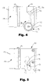
- Fig. 4 differs from that of the Fig. 3 . 3b and 7 Shown by the fact that it acts only unidirectionally and - as shown here - is primarily intended for the mechanical release by a fastened to the axis 22vonsbegrenzerseil. Both are optionally possible in all other embodiments.
- Said holder 25 is surrounded by a spring 28, which is designed as a compression spring and biases the roller 9 in the direction of the guide rail 2.
- This spring 28 counteracts a Soleniod (not shown), which is controlled by an electronic unit, not shown here, which is housed in the elevator shaft from which, if necessary, at least parts can also be installed cabin-fixed.
- the solenoid is de-energized when the braking or catching device should respond because either an emergency, ie an overspeed exists, or u. U. also because the elevator car is to be set in regular operation, z.
- the spring 28 moves the holder 25 and thus the roller 9 against the guide rail 2, so that this with its friction surface 12 (see Fig. 1 ) on the guide rail 2 (see Fig. 3 ) comes to the plant. It is thereby rotated, but also moved translationally relative to the pressure body 19. Namely, such that it soon not only touches the guide rail 2, but also the rear side, the groove 21, or, more precisely, the bottom of the groove 21st
- the roller 9 rotates clockwise (as viewed in FIG Fig. 3 ).
- the roller 9 once it has come back into contact with the bottom of the groove 21, with its friction surface or knurl 12 on the one hand on the guide rail 2 and on the other hand on the bottom of the groove 21.
- the roller 9 is getting deeper pulled into the wedge-shaped narrowing gap 20.
- the friction or contact conditions change on the role.
- the groove 21 is now so deep that the friction surface or knurl 12 loses contact with the bottom of the groove and the roller 9 rests on the pressure body side only with their shoulders 11 on the pressure body 19.
- the friction surface or knurl 12 has at least substantially clearance and the braking or catching friction is produced at least predominantly by the sliding of the shoulders 11 on the pressure body 19 or the fitting 33.
- the shoulders 11 predetermine the end position of the roll by pressing on the side of the press against a surface which is so steep that the roll can not be pulled further into the gap.
- the decisive first aspect of the invention in this context is in Fig. 3b to recognize.
- the pressure body 19 is provided with a fitting 33 of bearing metal, here in the form of bearing bronze. This is arranged and designed so that the shoulders 11 slide in the end position partially on the fitting 33 and partially directly on the base body, ie partially slide on the relative to the fitting 33 much firmer material of the body 19.
- a fitting 33 of bearing metal here in the form of bearing bronze.
- the fitting 33 is dimensioned and arranged so that the roller, once it has reached its end position, slides with part of the contact surface of its shoulders 11 on the fitting 33 consisting of bearing material and with the other part of the contact surface of its shoulders 11 on the harder material of the pressure hull 19. It goes without saying that the surface which represents the firmer of the two said sliding surfaces on the pressure body, does not necessarily have to be an integral part of the pressure hull 19, but z. B. also by a in the broadest sense attached to the actual pressure body, further fitting can be formed (not shown here, but claim variant).
- the roller or shoulders 11 of the roller are substantially harder or stronger than the bearing material of the fitting 33.
- the sliding of the shoulders 11 on the fitting 33 of the bearing material leads to a positive at the relatively high pressure that is encountered here
- This abrasion is introduced by the rotating roller in the surface area in which the roller with its shoulders 11 slides on the pressure body 19, and obviously fills the valleys of the surface roughness of the roller 9 on , It has been found that the abrasion can prevent effectively effective that it comes between the shoulders 11 of the roller 9 and the pressure body 19 to a seizure (local micro-welding and tearing) and thus destruction, as it is otherwise relatively quickly observed when steel slides under high surface pressure and speed on steel.
- the fitting 33 is subjected to significantly less wear by the roller than when the roller is fully or substantially exclusively slid on the fitting 33.
- the gap 20 or the gap-forming portion 20a can be designed so that the roller 9 in its End position a correspondingly higher pressure compared to the rail 2 and the pressure body 19 developed, resulting in a correspondingly higher, braking force acting frictional force results.
- the ratio of the surface with which the shoulders 11 slide in the final position of the roller 9 on the bearing material of the fitting 33 to the surface with which the shoulders 11 slide on the pressure body requires careful adjustment to the individual case.
- the surface with which the shoulders 11 of the roller 9 slide on the bearing material should not be unnecessarily large. Rather, it should be just so large that sufficient abrasion is generated to prevent between the shoulders 11 of the roller 9 and the Pressure body, where the greater part of the forces transmitted, seizure occurs.
- the expert can easily determine by experiments, as the area ratios are to be selected in the specific case.
- fittings 33 can be attached very easily.
- a suitably directed bolt from the bearing material is used or-pressed.
- the column 20 and the grooves 21 are milled into the pressure body 19.
- the bearing pin is cut and thereby automatically receives the correct contour. Namely, a contour, which looks like when the again dismantled fitting Fig. 6 illustrated.
- over-milling is taken to ensure that at least locally more than 180 ° of the total circumference of the bolt remain, which ensures that the bolt can not fall out of the cut by the over-drilled hole in the body.
- roller 9 rotates counterclockwise during braking in upward direction and therefore in the lower of the two in Fig. 3 imaged gap 20 is pulled.
- the elevator car In order to deactivate the braking or catching device after the deceleration of a downward movement of the elevator car, the elevator car is driven a bit far up in all embodiments.
- the skew of the gap 20 and the groove 21 are selected and matched so that the roller does not slide along the guide rail during this upward movement of the elevator car, but is now driven inversely by it and in the direction of its inactive position in the area between the upward pointing back and the down-facing gap section rolls back.
- the roller Once the roller has come close to its inactive position, it is retracted to its rest position (correspondingly connected solenoid) in good time before the roller is torn into the descending portion of the gap 20 from the inactive position of the roller and now there unintentionally brakes.
- a recess 32 is provided to reduce the rigidity of the pressure body 19 in the lower region.
- a correspondingly lower rigidity is effected in the section corresponding to an upward travel of the pressure body 19, and thus a lower contact pressure of the roller 9, resulting in a lower deceleration during braking.
- the ramps are not mirror-symmetrical, but executed with a different pitch or length, which also sets the desired effect. The measures are generally useful, ie can be used profitably in all of the embodiments shown, if necessary.
- the Fig. 10 illustrates the second, independent aspect of the invention, according to which one of the braking or catching acting to be provided on a guide rail 2 provided surface 43 opposite to the rail head 8 associated surface of the guide rail 2 is inclined.
- the inclined surface 43 is designed here in the form of a friction lining 15. This is rigidly attached to the leg 17 of the pressure body 19.
- the friction lining thus does not move with respect to the entire pressure body, ie it does not carry out a relative movement with respect to the leg 17 holding it, but moves with the leg 17.
- it comes with fully expanded pressure body with its friction surface largely completely on the associated surface of the guide rail 2 to the plant, whereby optimal friction and loading conditions are achieved.
- the inclination of the invention is particularly effective to advantage when the pressure body 19, the elasticity ensures the correct installation of the inclined surface at full load, not rigidly attached to the car, but as well as Fig. 11 shown.
- the pressure body 19 is here, comparable to the saddle of a vehicle disc brake, floatingly mounted on the elevator car. Serve as a guide for the floating storage per brake or catching each two spaced apart from each other on the elevator car rail-like structure, here in the form of flat iron F, which form a substantially horizontally aligned rail pair, so to speak.
- the pressure body 19 is provided at its upper and lower edge in each case with a groove N1 or N2 for engagement for the said flat iron, so that the pressure body can be inserted between the two flat iron.
- Both grooves have, compared to the width of the flat iron, a certain lateral play on.
- at least one of the two grooves N1 and N2 on a special design namely, it runs altogether sufficiently inclined. This takes into account the fact that the pressure body is elastically bent under the influence of the force with which the roller is pulled into the gap in the case of braking or catching, so that the two grooves respectively attached to the underside and the upper side no longer be aligned, unless appropriate action is taken.
- the oblique course or the helix angle ⁇ of the at least one groove is ideally chosen such that the groove still provides a precisely defined guide provided with a permissible clearance when the braking or catching device is inactive, namely because the lower edge of the left and the upper edge of the right Groove flank unfold a defined guiding effect.
- the fact that the groove flanks are inclined, ensures that the pressure body can deform without hindrance, without affecting the leadership.
- the inclined surface 43 is inclined by an angle ⁇ between 0.5 ° and 5 °.
- the first and the second aspect of the invention are initially independent of each other, ie, the inclination is also useful if no fitting is provided from a bearing material on which the roller partially slides and vice versa. If both measures are applied together, the result is a strong one combinatorial effect. Because the partial sliding of the roller 19 on the fitting of bearing material allows at substantially the same pressure significantly higher sliding speeds between the roller 9 and the pressure body 19 - and just these significantly higher sliding speeds or (at constant sliding speed) pressures dictate it make sure that the surfaces of the braking or catching device that come into contact with the guide rail as intended come into contact with the guide rail at full load and not only have inefficient line contact there.
- the groove 21 does not necessarily have to be designed on the side of the pressure hull. Instead, the groove can also be made on the roll, where it is flanked on both sides by knurled peripheral portions of the roll.
- the gap-forming portion 20a of the pressure body is then formed complementary in a corresponding manner.
Landscapes
- Engineering & Computer Science (AREA)
- Mechanical Engineering (AREA)
- Braking Arrangements (AREA)
- Maintenance And Inspection Apparatuses For Elevators (AREA)
- Bearings For Parts Moving Linearly (AREA)
- Lift-Guide Devices, And Elevator Ropes And Cables (AREA)
- Coating Apparatus (AREA)
Abstract
Description
Die Erfindung betrifft eine Brems- bzw. Fangeinrichtung für eine Aufzugskabine, die in einem Schacht entlang von vertikalen Führungsschienen gerührt ist. Dabei bedient sich die Brems- bzw. Fangeinrichtung einer mit einer Reibfläche versehenen Rolle als Bremskörper. Einmal aktiviert wird diese Rolle in einen Spalt hineingezogen. Dabei wird die die Reibung erzeugende Pressung immer größer, je weiter die Rolle in den Spalt in Richtung ihrer Endposition hineingezogen wird.The invention relates to a braking or catching device for an elevator car, which is stirred in a shaft along vertical guide rails. In this case, the braking or catching device uses a provided with a friction roller as a brake body. Once activated, this role is drawn into a gap. In this case, the friction generating pressure is always greater, the further the role is drawn into the gap in the direction of its final position.
Der Begriff "Aufzugsfahrkorb bzw. Fahrkorb" wird hier und im Folgenden als Sammelbegriff verwendet und umfasst sowohl herkömmliche Kombinationen aus Kabinen bzw. Lastträgem oder Plattformen aller Art, die von einem Fahrkorbrahmen getragen werden, als auch fahrkorbrahmenlose Konstruktionen.The term "elevator car or car" is used here and in the following as a collective term and includes both conventional combinations of cabins or load carriers or platforms of all kinds, which are supported by a car frame, as well as car frame-less constructions.
Brems- bzw. Fangeinrichtungen an Aufzügen dienen dazu, eine Aufzugskabine im Falle eines unkontrollierten Fahrzustandes oder einer unzulässig hohen Fahrgeschwindigkeit, wie sie z. B. bei einer Fehlfunktion der Steuerung oder eines Antriebs bzw. seiner Bremse sowie einem Seilbruch auftreten kann, abzubremsen.Braking or catching devices on elevators serve to lift an elevator car in the event of an uncontrolled driving condition or an impermissibly high driving speed, such as they z. B. in case of malfunction of the controller or a drive or its brake and a rope break may occur, decelerate.
Eine entsprechende Bremsfangeinrichtung ist zum Beispiel aus der Europäischen Patentanmeldung
Die von besagter Patentanmeldung vorgeschlagene Bremsfangeinrichtung ist von moderner Bauart, sie kommt mit nur wenigen Bauteilen aus. Anders, als die älteren Bremsfangeinrichtungen aus dem Stand der Technik, benötigt sie keine zusätzlichen Schrauben- oder Tellerfedern, um einen definierten Verlauf der Bremskraft bis hin zum Kabinenfang vorzugeben. Stattdessen ist das zur Montage an der Aufzugskabine vorgesehene und die Bremsrolle lagernde Gehäuse der Bremsfangeinrichtung (im Weiteren: der Druckkörper) hier so ausgebildet, dass es selbst eine definierte Federwirkung ausübt. Dies, indem der Druckkörper bei aktivierter Bremse auf der einen Seite ggf. unter Zwischenschaltung eines Reibbelags unmittelbar auf die Führungsschiene drückt und auf der anderen Seite mittelbar über die Bremsrolle auf die Führungsschiene drückt. Umso weiter die Bremsrolle in die ihr zugeordnete Nut entlang Richtung Anschlag gezogen wird, desto stärker wird der Druckkörper elastisch aufgedehnt. Entsprechend höher fallen die aktuellen Bremskräfte aus. Diese Federwirkung führt zusammen mit dem entsprechenden Layout der Nut bzw. des Spalts, wo die Bremsrolle unter starker Reibung abläuft, dazu, dass sich die gewünschte, definierte Bremswirkung einstellt.The proposed by said patent application brake catcher is of modern design, it comes with only a few components. Unlike the older brake catcher devices from the prior art, it requires no additional screw or disc springs to specify a defined course of the braking force up to the cabin catch. Instead, the intended for mounting on the elevator car and the brake roller overlapping housing of the brake catcher (hereinafter: the pressure body) is designed here so that it exerts itself a defined spring action. This, by the pressure body with activated brake on the one hand, possibly with the interposition of a friction lining presses directly on the guide rail and presses on the other side indirectly via the brake roller on the guide rail. The further the brake roller is pulled along its direction in the groove assigned to it, the stronger the pressure body is elastically expanded. The current braking forces are correspondingly higher. This spring effect, together with the corresponding layout of the groove or gap, where the brake roller runs under high friction, to the fact that sets the desired, defined braking effect.
Ein großer Vorteil dieser bekannten Bremsfangeinrichtung ist insbesondere der, dass ihr spezieller Aufbau schon von Hause aus weitgehend einer Fehlausrichtung zwischen der Führungsschiene und der Bremsfläche entgegenwirkt. Daher verursacht der Einsatz, d. h. die Aktivierung dieser Bremsfangeinrichtung, nur einen geringen Verschleiß an der Führungsschiene. Auch die Bremsfangeinrichtung selbst unterliegt nur einem geringen Verschleiß.A major advantage of this known brake catcher is in particular that its special design already largely counteracts home misalignment between the guide rail and the braking surface. Therefore, the use causes d. H. the activation of this brake catcher, only a slight wear on the guide rail. The brake catcher itself is only subject to low wear.
Wie diese bekannte Bremsfangeinrichtung ausgelöst wird, wird in besagter Patentanmeldung nicht explizit beschrieben. Für den Fachmann ist jedoch leicht erkennbar, dass diese Bremsfangeinrichtung für eine mechanische Betätigung üblicher Art vorgesehen ist. Dies, weil ihre Bremsrolle mit einem nach außen über das Gehäuse und sein Abdeckblech hinausstehenden, einseitigen Achsstummel ausgestattet ist. Dieser Achsstummel soll offensichtlich mittelbar oder unmittelbar mit dem im Schacht umlaufenden Seil eines üblichen Geschwindigkeitsbegrenzersystems verbunden sein, vgl.
Die von der
In einer zum Zeitpunkt der Erstanmeldung noch nicht veröffentlichten Patentanmeldung der Anmelderin wurde bereits vorgeschlagen, die Rolle in ihrer Endposition auf einem Einsatz bzw. Beschlag aus Buntmetall gleiten zu lassen. Dies, um so eine leichtere Lösbarkeit der Brems- bzw. Fangeinrichtung zu gewährleisten und sicherzustellen, dass auch bei oft wiederholter Betätigung der Brems- bzw. Fangeinrichtung stets annähernd die gleichen Reibungsverhältnisse auftreten. Indes ist eine solche Lösung, bei der die Rolle mit ihrer gesamten Fläche, über die sie reibend mit dem Druckkörper in Kontakt steht auf dem Buntmetall gleitet, nicht dazu geeignet, eine Brems- oder Fangeinrichtung zu realisieren, die ausgesprochen hohe Pressungen zwischen der Rolle und ihrem Gleitpartner entwickelt und damit ausgesprochen hohe Bremskräfte ermöglicht. Denn dort, wo die Rolle mit der gesamten besagten Fläche auf dem Buntmetall gleitet, sind die maximal zulässigen Pressungen von vorne herein begrenzt. Daher ist eine derartige Brems- bzw. Fangeinrichtung von Hause aus nicht in den Leistungsbereichen verwendbar, in denen bei stählerne Gleitpartner verwendenden Konstruktionen Fressen auftritt.In a not yet published at the time of the first application patent application of the Applicant has already been proposed to slide the role in its final position on a use or fitting of non-ferrous metal. This, in order to ensure an easier solubility of the braking or catching device and to ensure that even with often repeated operation of the braking or catching device almost always the same friction conditions occur. However, such a solution in which the roller with its entire surface over which it frictionally sliding contact with the pressure body on the non-ferrous metal, not suitable to realize a braking or catching device, the very high pressures between the roller and developed their sliding partner and thus allows extremely high braking forces. Because where the roller with the entire surface on the non-ferrous metal glides, the maximum allowable pressures are limited from the outset. Therefore, such a braking device is not usable by itself in the performance areas in which seizure occurs in constructions using steel sliding partners.
Es ist daher Aufgabe der Erfindung, Brems- bzw. Fangeinrichtungen der gattungsgemäßen Art dahingehend weiterzuentwickeln, dass es auch bei hohen Pressungen zwischen der Rolle und ihrem Gleitpartner nicht zum Fressen kommt.It is therefore an object of the invention to further develop braking or catching devices of the generic type such that it does not come to feed even at high pressures between the roller and its sliding partner.
Erfindungsgemäß wird dies bei einer Brems- bzw. Fangeinrichtung der eingangs genannten Art durch die Merkmale des Anspruchs 1 erreicht.According to the invention this is achieved in a braking or catching device of the type mentioned by the features of claim 1.
Die tribologischen Verhältnisse werden insgesamt (und damit das gesamte Gleitverhalten, auch dasjenige im Bereich der Stahlpaarung) dadurch wesentlich verbessert, dass der Spalt auf der Seite des Druckkörpers im Bereich seiner Endposition örtlich mit einem Beschlag aus Lagerwerkstoff versehen ist, der so gestaltet und angeordnet ist, dass die Rolle in ihrer Endposition teilweise auf dem Lagerwerkstoff gleitet und teilweise auf dem i. d. R. härteren Werkstoff des die restliche Gleitfläche bereitstellenden Druckkörpers. Diese restliche Gleitfläche muss dabei nicht zwingend ein integraler Bestandteil des Druckkörpers sein. Stattdessen kann es sich auch um einen weiteren Beschlag handeln, der an dem Druckkörper befestigt ist.The tribological conditions are overall (and thus the entire sliding behavior, including that in the steel pairing) significantly improved by the fact that the gap is provided on the side of the pressure hull in the region of its end position locally with a fitting of bearing material, which is designed and arranged in that, in its final position, the roller partly slides on the bearing material and partly on the i. d. R. harder material of the rest of the sliding surface providing pressure hull. This remaining sliding surface need not necessarily be an integral part of the pressure hull. Instead, it may also be another fitting that is attached to the pressure body.
Im Hinblick auf die Bedeutung des Worts Beschlag ist festzuhalten, dass ein Beschlag vorteilhafterweise (aber nicht zwingend) ein separates, an dem Druckkörper befestigtes Bauteil bedeutet. Vielmehr sind vom Grundsatz her auch Angüsse oder anderweitige dicke Beschichtungen erfasst. Allerdings ist es so, dass sich mit einem separat lösbar oder einmalig endgültig an dem Druckkörper befestigten und als Beschlag dienenden Bauteil die besten Ergebnisse erzielen lassen. Dies, weil auf besagte Art und Weise am einfachsten für einen Belag aus Lagerwerkstoff gesorgt werden kann, der die erforderliche Dicke und Abriebfestigkeit aufweist.With regard to the meaning of the word fitting, it should be noted that a fitting advantageously (but not necessarily) means a separate, attached to the pressure body component. Rather, in principle, sprues or otherwise thick coatings are covered. However, the best results can be achieved by means of a component that is fastened separately and / or permanently to the pressure body and serves as a fitting. This is because the easiest way to provide for a bearing made of bearing material, which has the required thickness and abrasion resistance in said manner.
Vorzugsweise besteht der Beschlag aus einem Buntmetall. Buntmetalle besitzen die erforderlichen tribologischen Eigenschaften. Idealerweise wird ein Buntmetall ausgewählt, das hohen Pressungen widerstehen kann. Ein solches Buntmetall ist beispielsweise Lagerbronze.Preferably, the fitting consists of a non-ferrous metal. Non-ferrous metals have the required tribological properties. Ideally, a non-ferrous metal is selected that can withstand high pressures. Such a non-ferrous metal is for example bearing bronze.
Im Rahmen einer bevorzugten Ausführungsform ist vorgesehen, dass der Druckkörper (bzw. der zusätzliche Beschlag, auf dem die Rolle neben dem Belag aus Lagerwerkstoff gleitet) aus vergütetem Stahl besteht, anstatt aus Federstahl. Das bringt merkliche Vorteile bei der spanenden Fertigung des Druckkörpers, denn Federstahl lässt sich nur ausgesprochen schlecht zerspanen.In the context of a preferred embodiment it is provided that the pressure body (or the additional fitting on which the roller next to the lining of bearing material glides) is made of tempered steel, instead of spring steel. This brings significant advantages in the machining of the pressure hull, because spring steel can only be machined extremely bad.
Vorzugsweise trägt die Rolle durch ihr Gleiten auf dem Lagerwerkstoff bzw. dem Beschlag aus Lagerwerkstoff bestimmungsgemäß Lagerwerkstoff ab und schleppt den abgetragenen Lagerwerkstoff in den Bereich ein, in dem die Rolle auf dem Druckkörper gleitet, d. h. die Stahloberfläche wird mit Buntmetallpartikeln versehen.Preferably, the role carries by their sliding on the bearing material or the fitting of bearing material intended from bearing material and drags the worn bearing material in the area in which the roller slides on the pressure body, d. H. The steel surface is provided with non-ferrous metal particles.
Sinnvollerweise trägt die Rolle in dem Bereich, mit dem sie im Laufe ihres Weges durch den Spalt bis kurz vor Erreichen ihrer Endposition zwischen der Führungsschiene und dem Druckkörper abwälzt, eine Profilierung, insbesondere eine Profilierung in Form einer Rändel. Sinn und Zweck einer solchen Profilierung ist es, die Reibungsverhältnisse derart zu beeinflussen, dass stets sichergestellt ist, dass die Rolle in der Phase, in der sie fortschreitend tiefer in den Spalt hineingezogen wird, sowohl an der Führungsschiene als auch am Druckkörper im Wesentlichen abrollt, und nicht nennenswert gleitet. Hierdurch erreicht die Rolle zuverlässig ihre Endposition. Zugleich gewährleistet die besagte Profilierung, dass die Rolle auch dann noch auf der Führungsschiene abrollt, wenn sie ihre Endposition erreicht hat. Nur so ist gewährleistet, dass der erfindungsgemäße Effekt eintritt.It makes sense that the role in the area with which it rolls in the course of their way through the gap until shortly before reaching their final position between the guide rail and the pressure body, a profiling, in particular a profiling in the form of a knurl. The purpose of such a profiling is to influence the friction conditions in such a way that it is always ensured that the roll substantially rolls both on the guide rail and on the pressure body in the phase in which it is progressively drawn deeper into the gap. and does not slide appreciably. As a result, the role reliably reaches its final position. At the same time, said profiling ensures that the roll still rolls on the guide rail when it has reached its final position. This is the only way to ensure that the effect according to the invention occurs.
Idealerweise ist die Rändel so beschaffen, dass es zwischen der Führungsschiene und der Rolle tatsächlich zu echter Haftreibung bzw. einer Kombination aus Haftreibung und evtl. Formschluss im Bereich der Rändelspitzen kommt, so dass die Rolle vollständig auf der Führungsschiene abrollt.Ideally, the knurl is designed so that between the guide rail and the role actually to real stiction or a combination of static friction and possibly positive fit in the area of the knurling tips, so that the roll rolls completely on the guide rail.
Eine Weiterbildung der Erfindung sieht vor, dass der Beschlag aus einem Bolzen eines geeigneten Lagerwerkstoffs besteht, der verdrehfest in einer entsprechenden Aufnahmebohrung des Druckkörpers gehalten ist. Dabei werden sowohl der Bolzen als auch die ihm zugeordnete Aufnahmebohrung zumindest in dem Bereich, in dem die Rolle bestimmungsgemäß auf dem Bolzen gleitet, überfräst bzw. überschliffen. Dies passiert, indem der Bolzen zunächst in die Bohrung eingesetzt wird, noch bevor die Kontur gefräst oder geschliffen wurde, die den Kontakt zwischen dem Druckkörper bzw. seinem Beschlag aus dem Lagerwerkstoff in der Rolle bestimmt. Die Fräs- oder Schleifbearbeitung erfolgt erst danach. Auf diese Art und Weise lässt sich der Beschlag aus dem Lagerwerkstoff einfach und ausgesprochen fest mit dem Druckkörper verbinden. Unter einem Bolzen wird dabei vorzugsweise Rundmaterial verstanden. Ein Vier-, Sechs- oder Mehrkantbolzen ist vom Prinzip her denkbar, jedoch de praxi eigentlich eher ein Theoretikum, da sich in den Druckkörper wesentlich einfacher eine entsprechende runde Aufnahme für den Bolzen einarbeiten lässt, als eine vier- oder mehrkantige.A development of the invention provides that the fitting consists of a bolt of a suitable bearing material, which is rotationally held in a corresponding receiving bore of the pressure hull. In this case, both the bolt and the receiving bore assigned to it are milled or ground over, at least in the region in which the roller slides as intended on the bolt. This is done by first inserting the bolt into the bore, even before the contour has been milled or ground, which determines the contact between the pressure body and its fitting from the bearing material determined in the role. The milling or grinding process takes place afterwards. In this way, the fitting of the bearing material can be easily and very firmly connected to the pressure hull. Under a bolt is preferably understood round material. A four-, six- or multi-bolt is conceivable in principle, but de praxi actually rather a Theoretikum, as in the pressure body much easier a corresponding round recording for the bolt can be incorporated, as a four- or more-edged.
Vorzugsweise ist der Anschlag, der den Weg begrenzt, den die Rolle in den Spalt hineingezogen wird, und der damit jeweils eine Endposition für die Rolle vorgibt, so ausgebildet, dass der Materialabtrag am Beschlag aus dem Lagerwerkstoff zumindest teilweise dadurch kompensiert wird, dass die Rolle etwas weiter in den Spalt zwischen dem Druckkörper und der Führungsschiene hineingezogen werden kann, wenn der Beschlag aus dem Lagerwerkstoff spürbar abgenutzt ist. Im Rahmen einer speziellen, sogleich noch näher zu beschreibenden, bevorzugten Ausführungsform wird dies dadurch erreicht, dass die bei besagter Ausführungsform verwendete Nut so ausgebildet ist, dass die Reibfläche bzw. Rändel der Rolle in Endposition auch dann noch den entsprechenden Freigang gegenüber dem Druckkörper hat, wenn der Beschlag etwas abgenutzt ist und dadurch über die Schultern der Rolle eine Endposition für die Rolle vorgibt, die nicht mehr ganz deren ursprünglicher Endposition entspricht.Preferably, the stop that limits the path that the roller is pulled into the gap, and thus each defines an end position for the role, designed so that the material removal at the fitting of the bearing material is at least partially compensated by the fact that the role can be pulled further into the gap between the pressure hull and the guide rail, when the fitting of the bearing material is noticeably worn. Within the scope of a specific embodiment, which will be described in more detail below, this is achieved in that the groove used in said embodiment is designed such that the friction surface or knurl of the roll in the end position still has the corresponding clearance with respect to the pressure body. if the fitting is a little worn and thereby provides over the shoulders of the role of an end position for the role, which no longer corresponds to their original end position.
Zwar stellt der Verschleiß auf Seiten des Beschlags aus dem Lagerwerkstoff im Regelfall kein allzu großes Problem dar. Dies, weil da nach den derzeitigen gesetzlichen Vorschriften und damit auch nach Maßgabe der Erfindung zunächst nicht mehr gefordert wird, als dass die Brems- bzw. Fangeinrichtung viermal hintereinander betätigt werden kann und dabei jeweils ordnungsgemäß funktioniert. Indes wird in jüngster Zeit zunehmend dazu übergegangen, die Brems- bzw. Fangeinrichtung nicht nur in Notfällen zu benutzen, sondern auch im regulären Betrieb - beispielsweise um ein Wegschleichen des Fahrkorbs aus seiner Haltestellenposition zu vereiteln oder um eine temporäre Schutzraumabsicherung vorzunehmen. Eine solche, zusätzliche Nutzung der Brems- bzw. Fangeinrichtung im regulären Bereich verlangt dann natürlich nach einer wesentlich größeren Verschleißfestigkeit. Diese kann nach Maßgabe des Gesagten erreicht werden.Although the wear on the part of the fitting from the bearing material usually does not pose a too great problem. This is because, according to the current statutory provisions and thus also in accordance with the invention, initially no longer required than that the braking or catching device four times can be actuated consecutively and each work properly. However, in recent years, increasingly adopted to use the brake or catching device not only in emergencies, but also in regular operation - for example, to thwart a creeping of the car from its stop position or to make a temporary shelter protection. Such, additional use of the braking or catching device in the regular area then of course requires a much greater wear resistance. This can be achieved in accordance with what has been said.
Im Rahmen einer weiteren vorteilhaften Ausführungsform der Erfindung ist vorgesehen, dass die Rolle beidseitig neben ihrem Abschnitt, der auf der Führungsschiene abwälzt, abgesetzte Schultern aufweist, die im Vergleich zu dem auf der Führungsschiene abwälzenden Abschnitt einen kleineren Durchmesser aufweisen. Gleichzeitig ist vorgesehen, dass der spaltbildende Abschnitt des Druckkörpers eine Nut zur Aufnahme der zum Kontakt mit der Führungsschiene vorgesehenen Reibfläche der Rolle aufweist. Dabei ist die Nut so gestaltet, dass, wenn sich die Rolle in ihrer Endposition befindet, Spiel zwischen der Reibfläche (am größten Umfang) der Rolle und der Nut besteht, so dass die Reibfläche keinen oder keinen wesentlichen Kontakt zum Druckkörper und dessen Beschlag hat und die Rolle druckkörperseitig zumindest im Wesentlichen nur durch die Gleitreibung zwischen den i. d. R. glatten Schultern und dem Druckkörper sowie dem Beschlag gebremst wird. Anders als zwischen der Reibfläche bzw. Rändel und dem Druckkörper kann zwischen den i. d. R. glatten Schultern und dem Druckkörper ein hohes Maß an Gleitreibung erzeugt werden, ohne dass nennenswerter Verschleiß auftritt - während eine stählerne Rändel beim Gleiten auf einem Beschlag aus Lagerwerkstoff unter hoher Pressung den Lagerwerkstoff buchstäblich abfräsen würde, bis sich die Rändel zugesetzt hat, reiben die i. d. R. glatten Schultern offensichtlich gerade nur so viel vom Beschlag ab, dass ein Fressen zwischen den in der Nachbarschaft aufeinander gleitenden Stahlflächen vermieden wird. Daher kann mit einer solchen Ausführung eine hohe Reibleistung (und damit eine entsprechende Brems- bzw. Fangwirkung) realisiert werden, indem die Geometrie und insbesondere der Keilwinkel des Spalts so gewählt werden, dass eine bis zu 35 % höhere Pressung erreicht wird, als bei Brems- bzw. Fangeinrichtungen, bei denen ausschließlich Stahlflächen aufeinander abgleiten.In a further advantageous embodiment of the invention it is provided that the roller on both sides next to its portion which rolls on the guide rail, shoulders offset, which have a smaller diameter compared to the rolling-off on the guide rail portion. At the same time it is provided that the gap-forming portion of the pressure body has a groove for receiving the provided for contact with the guide rail friction surface of the roller. In this case, the groove is designed so that when the roller is in its final position, play between the friction surface (the largest circumference) of the roller and the groove, so that the friction surface has no or no significant contact with the pressure body and its fitting and the role pressure body side, at least substantially only by the sliding friction between the i. d. R. smooth shoulders and the pressure body and the fitting is braked. Unlike between the friction surface or knurl and the pressure body can be between the i. d. R. smooth shoulders and the pressure hull a high degree of sliding friction are generated without significant wear occurs - while a steel knurl would literally mill the bearing material when sliding on a fitting of bearing material under high pressure until the knurled has, rub the i. d. Obviously, smooth shoulders are usually just so much fog that avoiding galling between adjacent steel surfaces in the neighborhood. Therefore, with such a design, a high friction power (and thus a corresponding braking or catching effect) can be realized by the geometry and in particular the wedge angle of the gap are selected so that up to 35% higher pressure is achieved, as in braking - or catching devices in which only steel surfaces slide on each other.
Ein weiterer Nachteil der ansonsten sehr weit entwickelten und ausgesprochen vorteilhaften Bremsfangeinrichtung gemäß
Es ist daher eine weitere Aufgabe der Erfindung, diesen Nachteil abzustellen.It is therefore a further object of the invention to remedy this disadvantage.
Diese Aufgabe wird nach einem weiteren Aspekt der Erfindung gemäß Anspruch 10 dadurch gelöst, dass zumindest eine der auf Seiten der Brems- bzw. Fangeinrichtung bestimmungsgemäß bremsend bzw. fangend wirkend zur Anlage an der Führungsschiene vorgesehenen Flächen bei inaktiver Brems- bzw. Fangeinrichtung gegenüber der ihr zugeordneten Fläche der Führungsschiene schräg gestellt ist. Die Schrägstellung muss dabei derart bemessen sein, dass sich die Fläche zumindest in der Phase, in der die Brems- bzw. Fangeinrichtung vollständig aktiviert ist, parallel zu der ihr wirkmäßig zugeordneten Fläche der Führungsschiene ausrichtet und im Wesentlichen vollflächig an ihr anliegt, d. h. dass die bestimmungsgemäß zum Kontakt mit der Führungsschiene vorgesehene Fläche in dieser, die stärkste Belastung ausmachenden Phase auch tatsächlich großflächig an der Führungsschiene anliegt. Vom Grundsatz her kann es sich bei der schräg gestellten Fläche sowohl um die Gegendruckfläche handeln (bevorzugt) als auch um die Fläche an der Rolle, die bestimmungsgemäß mit der Führungsschiene in Kontakt kommt. Der entscheidende Vorteil der Erfindung ist der, dass sich die Pressung und die Haft- bzw. Gleitreibungskräfte, sowie die dadurch erzeugte Wärme, gerade in der Phase maximaler Verzögerung und Belastung auf eine größere Fläche verteilen, was die Gefahr eines örtlichen Fließens, Verbrennens bzw. Verschweißens und Verschleißens der Reibflächen sowie einer Beschädigung der entsprechenden Flächen der Führungsschienen deutlich vermindert.This object is achieved according to a further aspect of the invention according to claim 10, characterized in that at least one of the braking or catching device intended braking or catching acting to rest on the guide rail surfaces provided inactive braking or catching device relative to hers assigned surface of the guide rail is inclined. The inclination must be dimensioned such that at least in the phase in which the braking or catching device is fully activated, the surface is aligned parallel to the surface of the guide rail which is actually associated with it and substantially bears against it over its whole area, ie. H. that intended for contact with the guide rail surface in this, the strongest load-making phase is actually applied over a large area on the guide rail. In principle, the inclined surface can be both the counter-pressure surface (preferred) and the surface on the roller that comes into contact with the guide rail as intended. The key advantage of the invention is that the pressure and the static or sliding friction forces, and the heat generated thereby, spread over a larger area, especially in the phase of maximum delay and load, which increases the risk of localized flow, burning or Welding and wear of the friction surfaces and damage to the corresponding surfaces of the guide rails significantly reduced.
Vorzugsweise wird die für die Ausrichtung der schräg gestellten Fläche erforderliche Beweglichkeit dadurch hergestellt, dass die sich schräg gestellte Fläche im Zuge der elastischen Aufweitung des Grundkörpers zusammen mit dem entsprechenden Schenkel des Grundkörpers relativ zu der zugeordneten Funktionsfläche der Führungsschiene bewegt. Dies, indem sie sich nicht nur auf die Führungsschiene zu bewegt, sondern in der Resultierenden auch eine Drehbewegung relativ zur Führungsschiene ausführt.Preferably, the mobility required for the alignment of the inclined surface is produced by the fact that the inclined surface moves in the course of the elastic expansion of the base body together with the corresponding leg of the body relative to the associated functional surface of the guide rail. This is achieved by not only moving towards the guide rail, but also performing a rotational movement relative to the guide rail in the resultant.
Es besteht also keine Notwendigkeit, die schräg gestellte Fläche drehbar und beweglich am Grundkörper zu lagern. Hierdurch werden mögliche Fehlerquellen beseitigt - übliche, bolzengeführte Schwenklagerungen stellen unvermeidlich eine Fehlerquelle dar, weil sie durch das typischerweise schlagartige Ansprechen der hier zur Diskussion stehenden Brems- bzw.So there is no need to store the inclined surface rotatably and movably on the body. This eliminates possible sources of error - usual, bolt-guided pivot bearings inevitably represent a source of error, because they by the typical sudden response of the brakes here under discussion or
Fangeinrichtungen u. U. ausschlagen bzw. Gefahr laufen, über die Jahre hinweg durch Schmutz und u. U. auch Korrosion schwergängig zu werden und ihre Funktion verlieren. Im Übrigen trägt der Verzicht auf ein übliches Schwenklager zur Kostenreduktion bei.Catching devices u. U. knock out or risk running over the years by dirt and u. U. also corrosion to become stiff and lose their function. Incidentally, the waiver of a conventional pivot bearing contributes to the cost reduction.
Vorzugsweise sind in der erfindungsgemäßen Brems- bzw. Fangeinrichtung keine Teller- oder Schraubenfedern verbaut. Denn solche Federn stellen nicht nur einen Kostenfaktor dar, sondern sind ebenfalls eine potentielle Fehlerquelle - gerade bei Schraubenfedern sind Federbrüche nie ganz auszuschließen, während gerade bei zu Paketen verschalteten Tellerfedern Gleit- und Haftreibungseinflüsse beim Einfedern auftreten, die unter ungünstigen Umständen spürbare Ungleichmäßigkeiten bzw. Abweichungen in der Reproduzierbarkeit auftreten lassen.Preferably no plate or coil springs are installed in the brake or catching device according to the invention. Because such springs are not only a cost factor, but are also a potential source of error - especially in coil springs spring breaks are never completely ruled out, especially when coupled to packages disc springs sliding and static friction influences occur during compression, which under unfavorable circumstances noticeable irregularities or deviations can occur in the reproducibility.
Bevorzugte Ausführungsbeispiele der Erfindung sind in den nachfolgend beschriebenen Figuren der Zeichnung dargestellt.Preferred embodiments of the invention are illustrated in the figures of the drawing described below.
Es zeigen:
- Fig. 1:
- schematisch ein Bremsorgan gemäß der Erfindung;
- Fig. 2:
- schematisch eine erfindungsgemäße Ausführungsform einer Brems- bzw. Fangeinrichtung in einem Horizontalschnitt;
- Fig. 3:
- die von
Fig. 2 gezeigte, bidirektional wirkende Brems- bzw. Fangeinrichtung in Richtung des Pfeils III vonFig. 2 gesehen; - Fig. 3b:
- die von
Fig. 3 gezeigte Ausführungsform bei in oberer Endposition befindlicher, mit ihrenSchultern 11 auf den Beschlag aus Lagerwerkstoff aufgelaufener Rolle - allerdings insoweit schematisch, als das inFig. 3 gezeigte und mit den genannten Bezugsziffern markierte Führungsblechmit dem Schlitz 23 und derHalter 25 ausgeblendet sind und der Druckkörper 19 entlang der Mitte einer der Schultern 11 geschnitten ist (der Übersicht halber wurde auf Schraffur verzichtet); - Fig. 4:
- ein zweites, als lediglich unidirektional wirkende Brems- bzw. Fangeinrichtung konzipiertes Ausführungsbeispiel - wiederum insoweit schematisch, als das besagte Führungsblech mit dem Schlitz ausgeblendet ist;
- Fig. 5:
- das von
Fig. 4 gezeigte Ausführungsbeispiel, allerdings ohne Ausblendung; - Fig. 6:
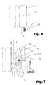
- das von
Fig. 5 gezeigte Ausführungsbeispiel in Ansicht senkrecht zu der Fläche der Führungsschiene, auf der die Rolle abrollt; - Fig. 7:
- ein drittes Ausführungsbeispiel, das sich vom ersten Ausführungsbeispiel durch die konstruktive Gestaltung des elektrischen Auslösemechanismus unterscheidet;
- Fig. 8:
- die unterschiedlichen Tiefen bzw. Verläufe der Spalte für vier verschiedene Nutzlastbereiche, d. h. vier verschiedene Mitglieder einer Baureihe mit ansonsten identischen Druckkörpern;
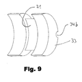
- Fig. 9:
- den von den Ausführungsbeispielen verwendeten Beschlag für sich allein gesehen;
- Fig. 10:
- eine andere Ausführungsform der erfindungsgemäßen Brems- und Fangeinrichtung, bei der der Schenkel des Druckkörpers, der die Gegendruckfläche bereit stellt, mit einer gegenüber der zugeordneten Fläche der Führungsschiene schräg gestellten Fläche ausgerüstet ist (wahlweise bidirektional oder unidirektional ausführbar);
- Fig. 11:
- eine anderweitige Darstellung der von
Fig. 10 gezeigten Ausführungsform, die sichtbar macht, wie der Druckkörper am Fahrkorb befestigbar ist.
- Fig. 1:
- schematically a brake member according to the invention;
- Fig. 2:
- schematically an embodiment of the invention a braking or catching device in a horizontal section;
- 3:
- the of
Fig. 2 shown, bidirectional braking or catching device in the direction of arrow III ofFig. 2 seen; - 3b:
- the of
Fig. 3 embodiment shown in befindlicher in upper end position, with theirshoulders 11 accumulated on the fitting of bearing material role - however, in so far as schematically, as inFig. 3 shown and marked with the above reference numerals guide plate with theslot 23 and theholder 25 are hidden and thepressure body 19 is cut along the center of the shoulders 11 (hatching omitted for clarity); - 4:
- a second, designed as only unidirectional braking or catching device embodiment - again in so far as schematically, as the said guide plate is hidden with the slot;
- Fig. 5:
- that from
Fig. 4 shown embodiment, but without suppression; - Fig. 6:
- that from
Fig. 5 embodiment shown in view perpendicular to the surface of the guide rail on which rolls the roll; - Fig. 7:
- a third embodiment, which differs from the first embodiment by the structural design of the electrical release mechanism;
- Fig. 8:
- the different depths or gradients of the column for four different payload areas, ie four different members of a series with otherwise identical pressure bodies;
- Fig. 9:
- seen the fitting used by the embodiments alone;
- Fig. 10:
- another embodiment of the braking and catching device according to the invention, in which the leg of the pressure body, which provides the counter-pressure surface is equipped with an inclined surface relative to the associated surface of the guide rail (optionally bidirectionally or unidirectionally executable);
- Fig. 11:
- another representation of the
Fig. 10 shown embodiment, which makes visible how the pressure hull on the car can be fastened.
Wie aus
Bei einer Brems- bzw. Fangeinrichtung nach Maßgabe der Erfindung ist ein Bremsorgan in Form einer Rolle 9 vorgesehen, die nahe ihrer beiden seitlichen Stirnflächen (siehe
Die
Die Rolle 9 ist drehbar auf einer z. B. in
Wie erwähnt und von den
Zwischen dem bei Aufwärtsfahrt und dem bei Abwärtsfahrt wirksamen Bereich des spaltbildenden Abschnitts bei den Ausführungsformen gemäß
Der Vollständigkeit halber ist anzumerken, dass auch solche Vorrichtungen möglich sind, die als nur unidirektional wirkende Brems- oder Fangeinrichtungen ausgeführt sind, d. h. die von der Rastfläche aus gesehen nur in einer Richtung mit einem Spalt 20 versehen sind, also nur mit dem oberen oder unteren Teil der von
Die Ausführungsformen gemäß
Das von
Demgegenüber bedient sich das von
Die Ausführungsform gemäß
Die Interaktion der Rolle bzw. der gesamten Brems- bzw. Fangeinrichtung mit der Führungsschiene soll nun stellvertretend für alle Ausführungsformen, die, was die Interaktion mit der Führungsschiene angeht, sinngemäß gleich funktionieren, an Hand des von den
Der besagte Halter 25 ist von einer Feder 28 umgeben, die als Druckfeder ausgebildet ist und die Rolle 9 in Richtung zur Führungsschiene 2 vorspannt. Dieser Feder 28 wirkt ein Soleniod (nicht dargestellt) entgegen, das von einer hier nicht gezeigten Elektronik angesteuert wird, die im Aufzugsschacht untergebracht ist, von der ggf. zumindest Teile auch kabinenfest eingebaut sein können.Said
Dabei wird das Solenoid entregt, wenn die Brems- bzw. Fangeinrichtung ansprechen soll, weil entweder ein Notfall, d. h. eine Übergeschwindigkeit vorliegt, oder aber u. U. auch, weil die Aufzugskabine im regulären Betrieb festgesetzt werden soll, z. B. im Rahmen von Wartungs- bzw. Servicearbeiten zur Schutzraumabsicherung oder um ein Wegschleichen der Aufzugskabine aus seiner Haltestellenposition zu verhindern. Dadurch bewegt die Feder 28 den Halter 25 und damit die Rolle 9 gegen die Führungsschiene 2, so dass diese mit ihrer Reibfläche 12 (siehe
Bei einer Abwärtsfahrt der Aufzugskabine dreht sich die Rolle 9 im Uhrzeigersinn (bei der Betrachtung gemäß
Der in diesem Zusammenhang entscheidende erste Aspekt der Erfindung ist in
Der Beschlag 33 ist so dimensioniert und angeordnet, dass die Rolle, sobald sie ihre Endposition erreicht hat, mit einem Teil der Kontaktfläche ihrer Schultern 11 auf dem aus Lagerwerkstoff bestehenden Beschlag 33 gleitet und mit dem anderen Teil der Kontaktfläche ihrer Schultern 11auf dem demgegenüber härteren Material des Druckkörpers 19. Es versteht sich von selbst, dass die Fläche, die die festere der beiden besagten Gleitflächen am Druckkörper darstellt, nicht zwingend ein integraler Bestandteil des Druckkörpers 19 sein muss, sondern z. B. auch durch einen im weitesten Sinne am eigentlichen Druckkörper befestigten, weiteren Beschlag gebildet werden kann (hier nicht gezeigte, aber anspruchsgemäße Variante).The fitting 33 is dimensioned and arranged so that the roller, once it has reached its end position, slides with part of the contact surface of its
Die Rolle bzw. die Schultern 11 der Rolle sind wesentlich härter bzw. fester als der Lagerwerkstoff des Beschlags 33. Das Gleiten der Schultern 11 auf dem Beschlag 33 aus dem Lagerwerkstoff führt bei der relativ hohen Pressung, die hier anzutreffen ist, zu einem sich positiv auswirkenden Abrieb bzw. Mikroabrieb auf Seiten des Beschlags 33. Dieser Abrieb wird durch die sich drehende Rolle in den Flächenbereich eingeschleppt, in dem die Rolle mit ihren Schultern 11 auf dem Druckkörper 19 gleitet, bzw. füllt offensichtlich die Täler der Oberflächenrauhigkeiten der Rolle 9 auf. Es hat sich herausgestellt, dass der Abrieb ausgesprochen wirkungsvoll zu verhindern vermag, dass es zwischen den Schultern 11 der Rolle 9 und dem Druckkörper 19 zu einem Fressen (lokale Mikroverschweißung und Wiederabreißen) und damit zu Zerstörung kommt, wie es sonst relativ schnell zu beobachten ist, wenn Stahl unter hoher Flächenpressung und Geschwindigkeit auf Stahl gleitet. Andererseits unterliegt der Beschlag 33 einer deutlich geringeren Abnutzung durch die Rolle, als bei vollständigem bzw. im Wesentlichen ausschließlichem Gleiten der Rolle auf dem Beschlag 33.The roller or
Dieser Effekt lässt sich dazu ausnutzen, bei weitgehend unveränderter Geometrie bzw. weitgehend unverändertem Materialaufwand die maximalen Bremskräfte und damit die Leistungsfähigkeit der Brems- bzw. Fangeinrichtung deutlich zu erhöhen. Da es bei Verwendung des erfindungsgemäßen Beschlages erst bei mindestens 30 % höheren Pressungen zu einem Fressen zwischen den Schultern 11 der Rolle 9 und dem Druckkörper 19 kommt, können der Spalt 20 bzw. der spaltbildende Abschnitt 20a so ausgelegt werden, dass die Rolle 9 in ihrer Endposition eine entsprechend höhere Pressung gegenüber der Schiene 2 und dem Druckkörper 19 entwickelt, woraus unmittelbar eine entsprechend höhere, bremsend wirkende Reibungskraft resultiert.This effect can be exploited to significantly increase the maximum braking forces and thus the performance of the braking or catching device with largely unchanged geometry or largely unchanged material costs. Since, when the fitting according to the invention is used, seizure between the
Das Verhältnis der Fläche, mit der die Schultern 11 in der Endposition der Rolle 9 auf dem Lagerwerkstoff des Beschlags 33 gleiten, zu der Fläche, mit der die Schultern 11 auf dem Druckkörper gleiten, bedarf der sorgfältigen Abstimmung auf den Einzelfall. Grundsätzlich gilt, dass die Fläche, mit der die Schultern 11 der Rolle 9 auf dem Lagerwerkstoff gleiten, nicht unnötig groß sein sollte. Sie sollte vielmehr gerade so groß sein, dass genügend Abrieb erzeugt wird, um zu verhindern, dass zwischen den Schultern 11 der Rolle 9 und dem Druckkörper, wo der größere Teil der Kräfte übertragen wird, Fressen auftritt. Hiervon ausgehend kann der Fachmann leicht durch Versuche ermitteln, wie die Flächenverhältnisse im konkreten Fall zu wählen sind.The ratio of the surface with which the
In erster Näherung lässt sich sagen, dass die gesamte Fläche, mit der die Rolle in Endposition auf dem Druckkörper 19 und dem Beschlag 33 gleitet, so aufgeteilt sein sollte, dass die Rolle möglichst nie mit mehr als 50 %, besser aber mit 20 % bis maximal 35 % bzw. 20 % bis 30 % ihrer besagten Fläche auf dem Beschlag 33 gleitet. Gerade zwischen den letztgenannten Grenzen lässt sich im Wege von Versuchen üblicher Art relativ einfach der Idealwert oder ein nah-idealer Wert für die Flächenverteilung finden.In a first approximation, it can be said that the entire surface with which the roller slides in the final position on the
Im Regelfall sollte auch dafür Sorge getragen werden, dass die profilierte Reibfläche bzw. Rändel 12 der Rolle 9 nicht (oder höchstens minimal bzw. kurzzeitig) mit dem Beschlag 33 in Kontakt kommt, so dass sich die profilierte Reibfläche bzw. Rändel 12 der Rolle nicht womöglich mit Abrieb zusetzt, den sie aus dem Beschlag 33 abgespant hat und dadurch ihrer eigentlichen Funktion beraubt wird - nämlich der Funktion sicherzustellen, dass zwischen der Rolle 9 und der Führungsschiene 2 im Wesentlichen kein Gleiten auftritt.As a rule, care should also be taken that the profiled friction surface or
Die insbesondere in
Auch eine Verdrehsicherung lässt sich vergleichsweise einfach realisieren. Dies z. B. indem der Beschlag mit einer Halbbohrung 34a versehen wird, mit dem eine an entsprechender Stelle des Druckkörpers 19 angebrachte Halbbohrung 34b derart korrespondiert, dass z. B. ein Kerbstift oder ein anderweitiger, passgenau Halt findender Bolzen eingeschlagen werden kann. Dieser verhindert dann durch seinen Formschluss ein Verdrehen, vgl.
Die bislang für eine Bremsung in Abwärtsfahrt bzw. bei unzulässigem Fall des Fahrkorbs geschilderten Verhältnisse sind bei Bremsung in Aufwärtsfahrt sinngemäß die gleichen, so dass das Gesagte entsprechend gilt. Man muss sich lediglich vor Augen führen, dass die Rolle 9 bei Bremsung in Aufwärtsfahrt gegen den Uhrzeigersinn dreht und daher in den unteren der beiden in
Um die Brems- bzw. Fangeinrichtung nach dem Abbremsen einer Abwärtsbewegung der Aufzugskabine wieder zu deaktivieren, wird die Aufzugskabine bei allen Ausführungsformen ein Stück weit nach oben gefahren. Die Schrägung des Spalts 20 und der Nut 21 sind so gewählt und aufeinander abgestimmt, dass die Rolle bei dieser Aufwärtsbewegung der Aufzugskabine nicht an der Führungsschiene entlanggleitet, sondern nun invers von ihr angetrieben wird und in die Richtung ihrer inaktiven Position im Bereich zwischen dem nach oben weisenden und dem nach unten weisenden Spaltabschnitt zurückwälzt. Sobald die Rolle in die Nähe ihrer inaktiven Position gelangt ist, wird sie bei (entsprechend beschaltetem Solenoid) in ihre Ruheposition zurückgezogen - und zwar rechtzeitig, bevor die Rolle in den von der inaktiven Position der Rolle aus absteigenden Abschnitt des Spalts 20 hineingerissen wird und nun dort unbeabsichtigt bremst.In order to deactivate the braking or catching device after the deceleration of a downward movement of the elevator car, the elevator car is driven a bit far up in all embodiments. The skew of the
Entsprechendes gilt für das Deaktivieren der Brems- bzw. Fangeinrichtung nach dem Abbremsen einer Aufwärtsbewegung der Aufzugskabine.The same applies to the deactivation of the braking or catching device after braking an upward movement of the elevator car.
Wie die Schrägung des Spalts 20 und der Nut 21 genau zu wählen sind, lässt sich nicht pauschal für alle möglichen Geometrien und Materialien der Brems- und Fangeinrichtung festlegen. Die genaue Auslegung im Einzelfall kann jedoch vom Fachmann leicht an Hand seines Fachwissens und der üblichen Berechnungen bzw. einer überschaubaren Anzahl von Versuchen ermittelt werden - die bei derartigen Brems- bzw. Fangeinrichtungen ohnehin erforderlich sind, da die Brems- bzw. Fangeinrichtungen schon auf Grund der technischen Vorschriften des Aufzugsbaus so ausgelegt sein müssen, dass sie im Falle einer Notbremsung nicht so hart verzögern, dass die Fahrgäste zu Fall kommen.How to choose the skew of the
Bei der in
Die
Die erfindungsgemäße Schrägstellung kommt besonders wirkungsvoll zur Geltung, wenn der Druckkörper 19, dessen Elastizität die korrekte Anlage der schräg gestellten Fläche bei Volllast gewährleistet, nicht starr am Fahrkorb befestigt ist, sondern so, wie von
Der Druckkörper 19 ist hier, vergleichbar mit dem Sattel einer Kfz-Scheibenbremse, schwimmend an der Aufzugskabine gelagert. Als Führung für die schwimmende Lagerung dienen pro Brems- bzw. Fangeinrichtung je zwei auf Abstand voneinander an der Aufzugskabine befestigte schienenartige Gebilde, hier in Form von Flacheisen F, die sozusagen ein im Wesentlichen horizontal ausgerichtetes Schienenpaar bilden. Der Druckkörper 19 ist an seiner Ober- und Unterkante jeweils mit einer Nut N1 bzw. N2 zum Eingriff für die besagten Flacheisen versehen, so dass der Druckkörper zwischen die beiden Flacheisen eingeschoben werden kann.The
Beide Nuten weisen, verglichen mit der Breite der Flacheisen, ein gewisses seitliches Spiel auf. Darüber hinaus weist zumindest eine der beiden Nuten N1 und N2 eine besondere Gestaltung auf, sie verläuft nämlich insgesamt hinreichend schräg. Damit wird dem Umstand Rechnung getragen, dass der Druckkörper unter dem Einfluss der Kraft, mit dem die Rolle im Falle des Bremsens oder Fangens in den Spalt hineingezogen wird, elastisch auf gebogen wird, so dass die beiden jeweils an der Unterseite und der Oberseite angebrachten Nuten nicht mehr miteinander fluchten, sofern keine entsprechenden Maßnahmen getroffen werden. Der Schrägverlauf bzw. der Schrägungswinkel α der zumindest einen Nut ist idealerweise so gewählt, dass die Nut bei inaktiver Brems- bzw. Fangeinrichtung nach wie vor eine genau definierte mit zulässigem Spiel versehene Führung gewährleistet, weil nämlich die Unterkante der linken und die Oberkante der rechten Nutflanke eine definierte Führungswirkung entfalten. Dadurch, dass die Nutflanken schräg verlaufen, ist gewährleistet, dass sich der Druckkörper ungehindert verformen kann, ohne die Führung zu beeinträchtigen.Both grooves have, compared to the width of the flat iron, a certain lateral play on. In addition, at least one of the two grooves N1 and N2 on a special design, namely, it runs altogether sufficiently inclined. This takes into account the fact that the pressure body is elastically bent under the influence of the force with which the roller is pulled into the gap in the case of braking or catching, so that the two grooves respectively attached to the underside and the upper side no longer be aligned, unless appropriate action is taken. The oblique course or the helix angle α of the at least one groove is ideally chosen such that the groove still provides a precisely defined guide provided with a permissible clearance when the braking or catching device is inactive, namely because the lower edge of the left and the upper edge of the right Groove flank unfold a defined guiding effect. The fact that the groove flanks are inclined, ensures that the pressure body can deform without hindrance, without affecting the leadership.
Idealerweise ist die schräg gestellte Fläche 43 um einen Winkel β zwischen 0,5° und 5° schräg gestellt.Ideally, the
Der erste und der zweite Aspekt der Erfindung stehen zunächst unabhängig nebeneinander, d. h. die Schrägstellung ist auch dann sinnvoll, wenn kein Beschlag aus einem Lagerwerkstoff vorgesehen wird, auf dem die Rolle teilweise gleitet und umgekehrt. Werden beide Maßnahmen gemeinsam miteinander angewandt, ergibt sich dennoch eine ausgeprägte kombinatorische Wirkung. Denn das teilweise Gleiten der Rolle 19 auf dem Beschlag aus Lagerwerkstoff ermöglicht bei im Wesentlichen gleicher Pressung deutlich höhere Gleitgeschwindigkeiten zwischen der Rolle 9 und dem Druckkörper 19 - und eben diese deutlich höheren Gleitgeschwindigkeiten bzw. (bei gleich bleibender Gleitgeschwindigkeit) Pressungen gebieten es, dafür zu sorgen, dass die bestimmungsgemäß mit der Führungsschiene in Kontakt kommenden Flächen der Brems- bzw. Fangeinrichtung bei Volllast sauber an der Führungsschiene anliegen und dort nicht nur ineffizienteren Linienkontakt haben.The first and the second aspect of the invention are initially independent of each other, ie, the inclination is also useful if no fitting is provided from a bearing material on which the roller partially slides and vice versa. If both measures are applied together, the result is a strong one combinatorial effect. Because the partial sliding of the
Ganz generell ist noch anzumerken, dass auch eine kinematische Umkehr des Prinzips "Rolle mit mittiger Rändel und seitlichen Schulten" bzw. "Druckkörper mit mittiger Nut und sich daran beidseitig anschließenden Auflageflächen" gewählt werden kann, ohne den Rahmen der Erfindung zu verlassen. Mit anderen Worten: Die Nut 21 muss nicht zwingend auf Seiten des Druckkörpers ausgeführt sein. Stattdessen kann die Nut auch an der Rolle ausgeführt sein, wo sie beidseitig von gerändelten Umfangsabschnitten der Rolle flankiert wird. Der spaltbildende Abschnitt 20a des Druckkörpers ist dann in entsprechender Weise komplementär ausgebildet. Insbesondere tritt dann an die Stelle der Nut 21 ein Vorsprung, der beidseitig von tiefer liegenden Abschnitten flankiert wird, die bestimmungsgemäß mit den Rändeln der Rolle in Kontakt kommen - bevor diese bei Erreichen der Endposition der Rolle abheben, so dass die Rolle nur noch auf dem Vorsprung gleitet.Quite generally, it should also be noted that a kinematic reversal of the principle "roll with central knurl and lateral shoulders" or "pressure body with central groove and support surfaces adjoining on both sides" can be selected without departing from the scope of the invention. In other words, the
Allerdings ist diese Abwandlung anfälliger gegen ein Verkanten der Rolle und daher nicht bevorzugt.However, this modification is more susceptible to tilting of the roller and therefore not preferred.
- 22
- Führungsschieneguide rail
- 66
- Steg der FührungsschieneBridge of the guide rail
- 77
- Schienenfußrail
- 88th
- Schienenkopfrailhead
- 99
- Rollerole
- 1111
- SchulternShoulder
- 1212
- Reibfläche der RolleFriction surface of the roller
- 1515
- Reibbelagfriction lining
- 1616
- Schenkelleg
- 1717
- Schenkelleg
- 1818
- am Druckkörper befestigtes Halteblechattached to the pressure hull retaining plate
- 1919
- Druckkörperpressure vessels
- 2020
- Spaltgap
- 20a20a
- spaltbildender Abschnittslit-forming section
- 2121
- Nutgroove
- 2222
- Achseaxis
- 2323
- Durchbruchbreakthrough
- 2525
- schwenkbarer Halterswiveling holder
- 2828
- Federfeather
- 3131
- Rastfläche zur Bestimmung der inaktiven RuhestellungDetent surface for determining the inactive rest position
- 3232
- Einschnittincision
- 3333
- Beschlag aus LagerwerkstoffFitting made of bearing material
- 3434
- Pass- bzw. Verdrehsicherungsstift für den BeschlagFitting or anti-rotation pin for fitting
- 34b34b
- Halbbohrungen zur Aufnahme des VerdrehsicherungsstiftsHalf holes for receiving the anti-rotation pin
- 4141
- Position, in der die Rolle im Nutgrund anliegtPosition in which the roller rests in the groove base
- 4242
- Position, in der die Schultern am Druckkörper anliegenPosition in which the shoulders abut the pressure body
- 4343
- schräggestellte Reibfläche (Gegendruckfläche)inclined friction surface (counter-pressure surface)
- DD
- Drehrichtungdirection of rotation
- N1N1
- erste Haltenut des Druckkörpersfirst retaining groove of the pressure hull
- N2N2
- zweite Haltenut des Druckkörperssecond retaining groove of the pressure hull
- FF
- Flacheisenflat iron
- αα
- Schrägungswinkel der NutHelix angle of the groove
- ββ
- Schrägungswinkel der ReibflächeHelix angle of the friction surface
Claims (21)
Priority Applications (7)
| Application Number | Priority Date | Filing Date | Title |
|---|---|---|---|
| AT07007905T ATE486811T1 (en) | 2007-04-18 | 2007-04-18 | BRAKE OR CATCHING DEVICE WITH A ROLLER PARTIALLY RUNNING ON A BRONZE COATING AND AN INCLINED FRICTION SURFACE |
| DE502007005550T DE502007005550D1 (en) | 2007-04-18 | 2007-04-18 | Braking or catching device with partially running on bronze pad roller and inclined friction surface |
| EP07007905A EP1982945B9 (en) | 2007-04-18 | 2007-04-18 | Braking or arresting device with a roller partly running on a bronze coating and an inclined friction surface |
| ES07007905T ES2353979T3 (en) | 2007-04-18 | 2007-04-18 | BRAKING OR ROLLING DEVICE WITH ROLLER THAT RUNS PARTIALLY ON BRONZE COATING AND INCLUDED FRICTION SURFACE. |
| PCT/EP2008/003034 WO2008128689A2 (en) | 2007-04-18 | 2008-04-16 | Decelerating or catching mechanism comprising a roll partly running on a bronze coating and an oblique frictional surface |
| RU2009137552/11A RU2438961C2 (en) | 2007-04-18 | 2008-04-16 | Braking or catching device with roller partially moving bronze sleeve and skewed friction surface |
| CN200880012697.7A CN101663221B (en) | 2007-04-18 | 2008-04-16 | Brake for elevator car |
Applications Claiming Priority (1)
| Application Number | Priority Date | Filing Date | Title |
|---|---|---|---|
| EP07007905A EP1982945B9 (en) | 2007-04-18 | 2007-04-18 | Braking or arresting device with a roller partly running on a bronze coating and an inclined friction surface |
Publications (3)
| Publication Number | Publication Date |
|---|---|
| EP1982945A1 true EP1982945A1 (en) | 2008-10-22 |
| EP1982945B1 EP1982945B1 (en) | 2010-11-03 |
| EP1982945B9 EP1982945B9 (en) | 2011-02-02 |
Family
ID=38523505
Family Applications (1)
| Application Number | Title | Priority Date | Filing Date |
|---|---|---|---|
| EP07007905A Active EP1982945B9 (en) | 2007-04-18 | 2007-04-18 | Braking or arresting device with a roller partly running on a bronze coating and an inclined friction surface |
Country Status (7)
| Country | Link |
|---|---|
| EP (1) | EP1982945B9 (en) |
| CN (1) | CN101663221B (en) |
| AT (1) | ATE486811T1 (en) |
| DE (1) | DE502007005550D1 (en) |
| ES (1) | ES2353979T3 (en) |
| RU (1) | RU2438961C2 (en) |
| WO (1) | WO2008128689A2 (en) |
Families Citing this family (3)
| Publication number | Priority date | Publication date | Assignee | Title |
|---|---|---|---|---|
| BR112018005224B1 (en) * | 2015-09-23 | 2021-11-16 | Inventio Ag | SLIDING CAPTURE DEVICE FOR AN LIFT SYSTEM, LIFT SYSTEM AND METHOD FOR BRAKING AN LIFT CABIN |
| DE202019105584U1 (en) * | 2019-10-10 | 2019-10-22 | Wittur Holding Gmbh | Tripping unit for actuating an elevator brake device |
| CN117446625A (en) * | 2023-10-27 | 2024-01-26 | 杭州西奥电梯有限公司 | A split tensioning traction wheel bushing and assembly method |
Citations (5)
| Publication number | Priority date | Publication date | Assignee | Title |
|---|---|---|---|---|
| GB2136773A (en) | 1983-03-21 | 1984-09-26 | Otis Elevator Co | Elevator safety device |
| EP0841280A1 (en) | 1996-11-07 | 1998-05-13 | Kone Oy | Safety gear |
| EP1061032A1 (en) * | 1998-12-02 | 2000-12-20 | Fabricacion de Elevadores, S.A. | Elastic element for brakes of guided systems |
| WO2006077243A1 (en) | 2005-01-21 | 2006-07-27 | Wittur Ag | Braking or interception device for a lift cabin |
| US20060180406A1 (en) * | 2004-12-17 | 2006-08-17 | Inventio Ag | Elevator installation with a braking device and method for braking and holding an elevator installation |
Family Cites Families (1)
| Publication number | Priority date | Publication date | Assignee | Title |
|---|---|---|---|---|
| SU1121225A1 (en) * | 1980-08-22 | 1984-10-30 | Ордена Октябрьской Революции Карачаровский Механический Завод | Lift safety |
-
2007
- 2007-04-18 EP EP07007905A patent/EP1982945B9/en active Active
- 2007-04-18 ES ES07007905T patent/ES2353979T3/en active Active
- 2007-04-18 AT AT07007905T patent/ATE486811T1/en active
- 2007-04-18 DE DE502007005550T patent/DE502007005550D1/en active Active
-
2008
- 2008-04-16 RU RU2009137552/11A patent/RU2438961C2/en active
- 2008-04-16 CN CN200880012697.7A patent/CN101663221B/en active Active
- 2008-04-16 WO PCT/EP2008/003034 patent/WO2008128689A2/en not_active Ceased
Patent Citations (5)
| Publication number | Priority date | Publication date | Assignee | Title |
|---|---|---|---|---|
| GB2136773A (en) | 1983-03-21 | 1984-09-26 | Otis Elevator Co | Elevator safety device |
| EP0841280A1 (en) | 1996-11-07 | 1998-05-13 | Kone Oy | Safety gear |
| EP1061032A1 (en) * | 1998-12-02 | 2000-12-20 | Fabricacion de Elevadores, S.A. | Elastic element for brakes of guided systems |
| US20060180406A1 (en) * | 2004-12-17 | 2006-08-17 | Inventio Ag | Elevator installation with a braking device and method for braking and holding an elevator installation |
| WO2006077243A1 (en) | 2005-01-21 | 2006-07-27 | Wittur Ag | Braking or interception device for a lift cabin |
Also Published As
| Publication number | Publication date |
|---|---|
| CN101663221A (en) | 2010-03-03 |
| RU2009137552A (en) | 2011-04-20 |
| WO2008128689A3 (en) | 2008-12-24 |
| EP1982945B9 (en) | 2011-02-02 |
| CN101663221B (en) | 2013-01-30 |
| DE502007005550D1 (en) | 2010-12-16 |
| ES2353979T3 (en) | 2011-03-08 |
| ATE486811T1 (en) | 2010-11-15 |
| RU2438961C2 (en) | 2012-01-10 |
| EP1982945B1 (en) | 2010-11-03 |
| WO2008128689A2 (en) | 2008-10-30 |
Similar Documents
| Publication | Publication Date | Title |
|---|---|---|
| DE69718131T2 (en) | safety device | |
| EP2925654B1 (en) | Device for catching a cabin in a lift assembly | |
| EP1902993B1 (en) | Auto resetting mechanism for a BCU type brake arresting device | |
| DE102015206345A1 (en) | Guide rail for an elevator system | |
| WO2021069739A1 (en) | Release unit for actuating an elevator brake device | |
| DE3715098A1 (en) | CASTING DEVICE FOR EXAMPLE FOR THE CAR BASKET OR THE COUNTERWEIGHT OF AN ELEVATOR SYSTEM | |
| EP1035965A1 (en) | V-belt drive | |
| EP1853504A1 (en) | Braking or interception device for a lift cabin | |
| EP3710325B1 (en) | Electromechanically switchable brake having integral damper structure | |
| EP1400476B1 (en) | Safety gear for elevators | |
| DE69715773T2 (en) | Sliding safety device | |
| DE102006036654B4 (en) | Wedge drive with forced return device | |
| EP1982945B9 (en) | Braking or arresting device with a roller partly running on a bronze coating and an inclined friction surface | |
| EP2102524B1 (en) | Disk brake comprising a self-energizing electromotive actuator | |
| EP2043937B1 (en) | Braking or holding device for temporarily ensuring a safe protected area and the like | |
| EP0899231A1 (en) | Double action braking device | |
| EP4077190B1 (en) | Safety brake device for a lift | |
| EP3774629B1 (en) | Clasp brake for an elevator system, serving in particular as a holding and safety brake | |
| EP4038002B1 (en) | Braking device | |
| DE102007038789A1 (en) | Clamping device and arrangement of such a clamping device with a collet | |
| WO1985002169A1 (en) | Safety brake device particularly for lift cabins | |
| EP4534466A2 (en) | Trigger unit for actuating an elevator brake device | |
| EP4217622A1 (en) | Brake application mechanism of a disk brake | |
| DE2133202A1 (en) | ADJUSTMENT DEVICE FOR THE AIR CLEARANCE OF A SPRING APPLICABLE AND ELECTROMAGNETIC VENTILATED BRAKE | |
| DE102004001568A1 (en) | Telescopic rail has roller fixed rotatable on outer rail so as to roll without wear on inner rail whilst being resiliently pretensioned against same |
Legal Events
| Date | Code | Title | Description |
|---|---|---|---|
| PUAI | Public reference made under article 153(3) epc to a published international application that has entered the european phase |
Free format text: ORIGINAL CODE: 0009012 |
|
| 17P | Request for examination filed |
Effective date: 20080712 |
|
| AK | Designated contracting states |
Kind code of ref document: A1 Designated state(s): AT BE BG CH CY CZ DE DK EE ES FI FR GB GR HU IE IS IT LI LT LU LV MC MT NL PL PT RO SE SI SK TR |
|
| AX | Request for extension of the european patent |
Extension state: AL BA HR MK RS |
|
| 17Q | First examination report despatched |
Effective date: 20090306 |
|
| AKX | Designation fees paid |
Designated state(s): AT BE BG CH CY CZ DE DK EE ES FI FR GB GR HU IE IS IT LI LT LU LV MC MT NL PL PT RO SE SI SK TR |
|
| GRAP | Despatch of communication of intention to grant a patent |
Free format text: ORIGINAL CODE: EPIDOSNIGR1 |
|
| GRAS | Grant fee paid |
Free format text: ORIGINAL CODE: EPIDOSNIGR3 |
|
| GRAA | (expected) grant |
Free format text: ORIGINAL CODE: 0009210 |
|
| AK | Designated contracting states |
Kind code of ref document: B1 Designated state(s): AT BE BG CH CY CZ DE DK EE ES FI FR GB GR HU IE IS IT LI LT LU LV MC MT NL PL PT RO SE SI SK TR |
|
| REG | Reference to a national code |
Ref country code: GB Ref legal event code: FG4D Free format text: NOT ENGLISH |
|
| REG | Reference to a national code |
Ref country code: CH Ref legal event code: EP |
|
| REG | Reference to a national code |
Ref country code: IE Ref legal event code: FG4D Free format text: LANGUAGE OF EP DOCUMENT: GERMAN |
|
| REF | Corresponds to: |
Ref document number: 502007005550 Country of ref document: DE Date of ref document: 20101216 Kind code of ref document: P |
|
| REG | Reference to a national code |
Ref country code: ES Ref legal event code: FG2A Effective date: 20110224 |
|
| REG | Reference to a national code |
Ref country code: NL Ref legal event code: VDEP Effective date: 20101103 |
|
| LTIE | Lt: invalidation of european patent or patent extension |
Effective date: 20101103 |
|
| PG25 | Lapsed in a contracting state [announced via postgrant information from national office to epo] |
Ref country code: LT Free format text: LAPSE BECAUSE OF FAILURE TO SUBMIT A TRANSLATION OF THE DESCRIPTION OR TO PAY THE FEE WITHIN THE PRESCRIBED TIME-LIMIT Effective date: 20101103 |
|
| REG | Reference to a national code |
Ref country code: IE Ref legal event code: FD4D |
|
| PG25 | Lapsed in a contracting state [announced via postgrant information from national office to epo] |
Ref country code: LV Free format text: LAPSE BECAUSE OF FAILURE TO SUBMIT A TRANSLATION OF THE DESCRIPTION OR TO PAY THE FEE WITHIN THE PRESCRIBED TIME-LIMIT Effective date: 20101103 Ref country code: FI Free format text: LAPSE BECAUSE OF FAILURE TO SUBMIT A TRANSLATION OF THE DESCRIPTION OR TO PAY THE FEE WITHIN THE PRESCRIBED TIME-LIMIT Effective date: 20101103 Ref country code: SI Free format text: LAPSE BECAUSE OF FAILURE TO SUBMIT A TRANSLATION OF THE DESCRIPTION OR TO PAY THE FEE WITHIN THE PRESCRIBED TIME-LIMIT Effective date: 20101103 Ref country code: IS Free format text: LAPSE BECAUSE OF FAILURE TO SUBMIT A TRANSLATION OF THE DESCRIPTION OR TO PAY THE FEE WITHIN THE PRESCRIBED TIME-LIMIT Effective date: 20110303 Ref country code: PT Free format text: LAPSE BECAUSE OF FAILURE TO SUBMIT A TRANSLATION OF THE DESCRIPTION OR TO PAY THE FEE WITHIN THE PRESCRIBED TIME-LIMIT Effective date: 20110303 Ref country code: NL Free format text: LAPSE BECAUSE OF FAILURE TO SUBMIT A TRANSLATION OF THE DESCRIPTION OR TO PAY THE FEE WITHIN THE PRESCRIBED TIME-LIMIT Effective date: 20101103 Ref country code: SE Free format text: LAPSE BECAUSE OF FAILURE TO SUBMIT A TRANSLATION OF THE DESCRIPTION OR TO PAY THE FEE WITHIN THE PRESCRIBED TIME-LIMIT Effective date: 20101103 Ref country code: BG Free format text: LAPSE BECAUSE OF FAILURE TO SUBMIT A TRANSLATION OF THE DESCRIPTION OR TO PAY THE FEE WITHIN THE PRESCRIBED TIME-LIMIT Effective date: 20110203 |
|
| PG25 | Lapsed in a contracting state [announced via postgrant information from national office to epo] |
Ref country code: CZ Free format text: LAPSE BECAUSE OF FAILURE TO SUBMIT A TRANSLATION OF THE DESCRIPTION OR TO PAY THE FEE WITHIN THE PRESCRIBED TIME-LIMIT Effective date: 20101103 Ref country code: IE Free format text: LAPSE BECAUSE OF FAILURE TO SUBMIT A TRANSLATION OF THE DESCRIPTION OR TO PAY THE FEE WITHIN THE PRESCRIBED TIME-LIMIT Effective date: 20101103 Ref country code: EE Free format text: LAPSE BECAUSE OF FAILURE TO SUBMIT A TRANSLATION OF THE DESCRIPTION OR TO PAY THE FEE WITHIN THE PRESCRIBED TIME-LIMIT Effective date: 20101103 |
|
| PG25 | Lapsed in a contracting state [announced via postgrant information from national office to epo] |
Ref country code: DK Free format text: LAPSE BECAUSE OF FAILURE TO SUBMIT A TRANSLATION OF THE DESCRIPTION OR TO PAY THE FEE WITHIN THE PRESCRIBED TIME-LIMIT Effective date: 20101103 Ref country code: PL Free format text: LAPSE BECAUSE OF FAILURE TO SUBMIT A TRANSLATION OF THE DESCRIPTION OR TO PAY THE FEE WITHIN THE PRESCRIBED TIME-LIMIT Effective date: 20101103 Ref country code: RO Free format text: LAPSE BECAUSE OF FAILURE TO SUBMIT A TRANSLATION OF THE DESCRIPTION OR TO PAY THE FEE WITHIN THE PRESCRIBED TIME-LIMIT Effective date: 20101103 Ref country code: SK Free format text: LAPSE BECAUSE OF FAILURE TO SUBMIT A TRANSLATION OF THE DESCRIPTION OR TO PAY THE FEE WITHIN THE PRESCRIBED TIME-LIMIT Effective date: 20101103 |
|
| PLBE | No opposition filed within time limit |
Free format text: ORIGINAL CODE: 0009261 |
|
| STAA | Information on the status of an ep patent application or granted ep patent |
Free format text: STATUS: NO OPPOSITION FILED WITHIN TIME LIMIT |
|
| 26N | No opposition filed |
Effective date: 20110804 |
|
| BERE | Be: lapsed |
Owner name: WITTUR HOLDING G.M.B.H. Effective date: 20110430 |
|
| PG25 | Lapsed in a contracting state [announced via postgrant information from national office to epo] |
Ref country code: MC Free format text: LAPSE BECAUSE OF NON-PAYMENT OF DUE FEES Effective date: 20110430 |
|
| REG | Reference to a national code |
Ref country code: CH Ref legal event code: PL |
|
| REG | Reference to a national code |
Ref country code: DE Ref legal event code: R097 Ref document number: 502007005550 Country of ref document: DE Effective date: 20110804 |
|
| PG25 | Lapsed in a contracting state [announced via postgrant information from national office to epo] |
Ref country code: MT Free format text: LAPSE BECAUSE OF FAILURE TO SUBMIT A TRANSLATION OF THE DESCRIPTION OR TO PAY THE FEE WITHIN THE PRESCRIBED TIME-LIMIT Effective date: 20101103 |
|
| PG25 | Lapsed in a contracting state [announced via postgrant information from national office to epo] |
Ref country code: LI Free format text: LAPSE BECAUSE OF NON-PAYMENT OF DUE FEES Effective date: 20110430 Ref country code: CH Free format text: LAPSE BECAUSE OF NON-PAYMENT OF DUE FEES Effective date: 20110430 Ref country code: BE Free format text: LAPSE BECAUSE OF NON-PAYMENT OF DUE FEES Effective date: 20110430 |
|
| REG | Reference to a national code |
Ref country code: DE Ref legal event code: R082 Ref document number: 502007005550 Country of ref document: DE Representative=s name: MARTIN MISSELHORN PATENT- UND RECHTSANWALT, DE Ref country code: DE Ref legal event code: R082 Ref document number: 502007005550 Country of ref document: DE Representative=s name: MISSELHORN WALL PATENT- UND RECHTSANWAELTE, DE |
|
| PG25 | Lapsed in a contracting state [announced via postgrant information from national office to epo] |
Ref country code: LU Free format text: LAPSE BECAUSE OF NON-PAYMENT OF DUE FEES Effective date: 20110418 Ref country code: CY Free format text: LAPSE BECAUSE OF FAILURE TO SUBMIT A TRANSLATION OF THE DESCRIPTION OR TO PAY THE FEE WITHIN THE PRESCRIBED TIME-LIMIT Effective date: 20101103 |
|
| REG | Reference to a national code |
Ref country code: DE Ref legal event code: R082 Ref document number: 502007005550 Country of ref document: DE Representative=s name: MARTIN MISSELHORN PATENT- UND RECHTSANWALT, DE |
|
| REG | Reference to a national code |
Ref country code: AT Ref legal event code: MM01 Ref document number: 486811 Country of ref document: AT Kind code of ref document: T Effective date: 20120418 |
|
| PG25 | Lapsed in a contracting state [announced via postgrant information from national office to epo] |
Ref country code: AT Free format text: LAPSE BECAUSE OF NON-PAYMENT OF DUE FEES Effective date: 20120418 |
|
| PG25 | Lapsed in a contracting state [announced via postgrant information from national office to epo] |
Ref country code: HU Free format text: LAPSE BECAUSE OF FAILURE TO SUBMIT A TRANSLATION OF THE DESCRIPTION OR TO PAY THE FEE WITHIN THE PRESCRIBED TIME-LIMIT Effective date: 20101103 |
|
| REG | Reference to a national code |
Ref country code: DE Ref legal event code: R082 Ref document number: 502007005550 Country of ref document: DE Representative=s name: MISSELHORN, MARTIN, DIPL.-ING., DE Effective date: 20131114 Ref country code: DE Ref legal event code: R082 Ref document number: 502007005550 Country of ref document: DE Representative=s name: MISSELHORN, MARTIN, DIPL.-ING., DE Effective date: 20120402 Ref country code: DE Ref legal event code: R082 Ref document number: 502007005550 Country of ref document: DE Representative=s name: MISSELHORN, MARTIN, DIPL.-ING., DE Effective date: 20130614 Ref country code: DE Ref legal event code: R081 Ref document number: 502007005550 Country of ref document: DE Owner name: WITTUR HOLDING GMBH, DE Free format text: FORMER OWNER: WITTUR HOLDING GMBH, 85259 WIEDENZHAUSEN, DE Effective date: 20131114 |
|
| REG | Reference to a national code |
Ref country code: GR Ref legal event code: EP Ref document number: 20100403037 Country of ref document: GR Effective date: 20110119 |
|
| REG | Reference to a national code |
Ref country code: FR Ref legal event code: PLFP Year of fee payment: 10 |
|
| REG | Reference to a national code |
Ref country code: FR Ref legal event code: PLFP Year of fee payment: 11 |
|
| REG | Reference to a national code |
Ref country code: FR Ref legal event code: PLFP Year of fee payment: 12 |
|
| PGFP | Annual fee paid to national office [announced via postgrant information from national office to epo] |
Ref country code: GR Payment date: 20230418 Year of fee payment: 17 |
|
| PG25 | Lapsed in a contracting state [announced via postgrant information from national office to epo] |
Ref country code: GR Free format text: LAPSE BECAUSE OF NON-PAYMENT OF DUE FEES Effective date: 20241104 |
|
| PG25 | Lapsed in a contracting state [announced via postgrant information from national office to epo] |
Ref country code: GR Free format text: LAPSE BECAUSE OF NON-PAYMENT OF DUE FEES Effective date: 20241104 |
|
| PGFP | Annual fee paid to national office [announced via postgrant information from national office to epo] |
Ref country code: DE Payment date: 20250417 Year of fee payment: 19 |
|
| PGFP | Annual fee paid to national office [announced via postgrant information from national office to epo] |
Ref country code: GB Payment date: 20250423 Year of fee payment: 19 Ref country code: ES Payment date: 20250519 Year of fee payment: 19 |
|
| PGFP | Annual fee paid to national office [announced via postgrant information from national office to epo] |
Ref country code: IT Payment date: 20250430 Year of fee payment: 19 |
|
| PGFP | Annual fee paid to national office [announced via postgrant information from national office to epo] |
Ref country code: FR Payment date: 20250428 Year of fee payment: 19 |
|
| PGFP | Annual fee paid to national office [announced via postgrant information from national office to epo] |
Ref country code: TR Payment date: 20250410 Year of fee payment: 19 |