EP1982891B9 - Drehrahmen und Schienenfahrzeug - Google Patents
Drehrahmen und Schienenfahrzeug Download PDFInfo
- Publication number
- EP1982891B9 EP1982891B9 EP20080154826 EP08154826A EP1982891B9 EP 1982891 B9 EP1982891 B9 EP 1982891B9 EP 20080154826 EP20080154826 EP 20080154826 EP 08154826 A EP08154826 A EP 08154826A EP 1982891 B9 EP1982891 B9 EP 1982891B9
- Authority
- EP
- European Patent Office
- Prior art keywords
- frame
- locking
- swung
- top frame
- bottom frame
- Prior art date
- Legal status (The legal status is an assumption and is not a legal conclusion. Google has not performed a legal analysis and makes no representation as to the accuracy of the status listed.)
- Active
Links
Images


Classifications
-
- B—PERFORMING OPERATIONS; TRANSPORTING
- B61—RAILWAYS
- B61D—BODY DETAILS OR KINDS OF RAILWAY VEHICLES
- B61D3/00—Wagons or vans
- B61D3/04—Wagons or vans with movable floors, e.g. rotatable or floors which can be raised or lowered
-
- B—PERFORMING OPERATIONS; TRANSPORTING
- B61—RAILWAYS
- B61D—BODY DETAILS OR KINDS OF RAILWAY VEHICLES
- B61D3/00—Wagons or vans
- B61D3/16—Wagons or vans adapted for carrying special loads
- B61D3/20—Wagons or vans adapted for carrying special loads for forwarding containers
-
- B—PERFORMING OPERATIONS; TRANSPORTING
- B61—RAILWAYS
- B61D—BODY DETAILS OR KINDS OF RAILWAY VEHICLES
- B61D47/00—Loading or unloading devices combined with vehicles, e.g. loading platforms, doors convertible into loading and unloading ramps
Definitions
- the invention relates to a swivel frame for a rail vehicle, comprising a bottom frame for fixing on an undercarriage of the rail vehicle, and a top frame for accommodating a container, which top frame is connected to the bottom frame so that it can swing between a swung-in position, in which the top frame runs substantially parallel to the bottom frame, and a swung-out position, in which the top frame runs at an angle relative to the bottom frame, wherein the bottom frame is provided with a number of corner blocks, which can be fixed detachably on the undercarriage of the rail vehicle, the swivel frame further comprising a locking mechanism, having a locking position, in which in the swung-in position the top frame is locked relative to the bottom frame, and having a releasing position, in which the top frame can swing from its swung-in position relative to the bottom frame.
- NL8800161 discloses a swivel platform for a rail vehicle.
- the swivel platform is intended for loading a container from a road vehicle onto the rail vehicle, and vice versa.
- the bottom frame has two longitudinal beams, which are connected by three transverse bottom plates. In practice, the bottom plates are approximately 12 - 15 mm thick.
- the bottom frame is permanently fixed on a rail wagon, so that the swivel platform forms an integral part of the rail wagon.
- Such an adapted rail wagon is suitable only for the transport of so-called ACTS containers, i.e. containers which can be transferred between a road vehicle and a rail vehicle.
- EP 0 911 238 A1 discloses a transport device for containers on railway wagons.
- the transport device comprises a base frame which supports a rotating frame on a rotary bearing mounting.
- the rotaring frame has tracks for the container base rollers, as well as angled rails to guide and hold the container.
- the rotating frame can be locked relative to the base frame.
- the entire transport device can be removed by a crane from the railway wagon, so that the wagon can be used for other freight.
- EP 0 516 586 A1 discloses a lateral locking device of a turning platform on a railcar.
- the locking device has a bolt which is held by gravity in the closed position. After the bolt has been moved into the open position, it can be moved over by the two supporting rails of the turning platform when turning outwards and when turning back inwards. When the travel position is achieved again, the bolt moves back automatically in the closed position again.
- An opening lever is provided to move the bolt into the open position. The opening lever drops back into its initial position when the turning platform is turning outwards.
- An object of the invention is to provide an improved swivel frame for a rail vehicle.
- the locking mechanism comprises a set of first swing-out locks arranged on either side of the top frame and a set of second swing-out locks, arranged on either side of the top frame as well, for locking the top-frame relative to the bottom frame, each of the swing-out locks having a locking position and a releasing position.
- the corner blocks are, for example, of an ISO standard design, i.e. the corner blocks form so-called standardized corner castings.
- the corner blocks can be fixed detachably on a standard container rail vehicle, for example by means of so-called "ISO locking pins"
- the swivel frame according to the invention constitutes a removable swap body.
- the swivel frame fits as an adapter on a standard container piggyback wagon for rail transport.
- use of the swivel frame is flexible.
- a swivel frame fixed on a rail wagon is easy to remove from it, after which that rail wagon can be used again as a standard container piggyback wagon.
- standard container piggyback wagons for rail transport are relatively cheap to hire, even for quite short periods, so that the investment costs for use of ACTS containers are considerably reduced.
- an ACTS hire company can also respond flexibly and quickly to demands from the market.
- the bottom frame is designed in such a way that the bottom frame can be fixed only by means of the corner blocks on the undercarriage of the rail vehicle.
- the bottom frame is secured on the undercarriage of the rail vehicle only by means of the corner blocks.
- the bottom frame is self-supporting, i.e. the bottom frame can bear a container loaded onto the swivel frame without support between the corner blocks.
- the forces exerted by the container upon the top frame are transmitted by the bottom frame to the corner blocks, after which the corner blocks divert these forces into the rail vehicle.
- the undercarriage of the swivel platform disclosed in NL8800161 would give way under the influence of the weight of a container if its beams and bedplates were not supported by a rail vehicle undercarriage.
- a first locking mechanism which locking mechanism has a locking position in which in the swung-in position the top frame is locked relative to the bottom frame, and has a releasing position in which the top frame can swing from its swung-in position relative to the bottom frame.
- the locking mechanism can comprise a blocking element, which can pivot about a first pivot axis between a first position and a second position, which positions correspond to the locking position and the releasing position respectively, the blocking element having a stop, which in the first position of the blocking element secures the top frame in the swung-in position.
- the blocking element can be operated in various ways.
- the locking mechanism has an operating handle, which operating handle can pivot about a second pivot axis between a first position and a second position, which positions correspond to the locking position and the releasing position respectively, the first pivot axis and the second pivot axis running at a mutual distance and substantially parallel to each other, and the blocking element being movable by the operating handle.
- the blocking element in this case can pivot about the first pivot axis between two positions, which positions correspond to the locking position and the releasing position respectively.
- the operating handle can pivot about a second pivot axis running substantially at a distance from and parallel to the first pivot axis.
- the operating handle likewise has two positions, which positions correspond to the locking position and the releasing position respectively.
- the stop of the blocking element prevents the top frame from swinging out from the swung-in position. After all, the stop of the blocking element retains the top frame.
- the blocking element is taken to its second position, in which the stop of the blocking element is moved away out of the path of the top frame. The top frame can then swing out relative to the bottom frame.
- the blocking element and the operating handle can be designed in various ways.
- the blocking element and the operating handle are pivotably connected to each other, or the operating handle has an eccentric cam which is accommodated loosely in a corresponding recess in the blocking element.
- the swivel platform for a rail vehicle disclosed in NL8800161 has a locking pin, which is pretensioned by a spring towards a securing position.
- An operating handle can unlock the locking pin.
- the locking pin can, however, become stuck through wear or damage.
- the operating handle then shows a locked state, whilst the swivel frame is not locked.
- the locking according to the abovementioned embodiment of the invention has a forced locking movement with a pivoting blocking element.
- the first position of the operating handle corresponding to the locking position forms a lowered position, in which the operating handle lies below the horizontal plane defined by the underside of the top frame, and in which the second position of the operating handle corresponding to the releasing position forms an upstanding position, in which the operating handle projects upwards relative to said plane, and in which the blocking element is movable from its first position corresponding to the locking position to its second position corresponding to the releasing position by moving the operating handle from the lowered position to the upstanding position, and in which the operating handle is forced by the top frame from the upstanding position to the lowered position when the top frame swings from the swung-in position to the swung-out position. In this way it is ensured that the top frame is locked unless the operating handle is raised.
- the centre of gravity of the blocking element can lie at such a distance from the first pivot axis that the blocking element moves to the locking position under the influence of gravity when the operating handle is in the lowered position. This means that under the influence of gravity, the blocking element is "pretensioned” towards the locking position. While the top frame is swinging inwards from the swung-out position, the top frame slides over the blocking element. In the process, the top frame pushes the stop of the blocking element slightly downwards. As soon as the top frame has swung past the blocking element, the stop of the blocking element goes up again immediately under the influence of gravity. The blocking element is then in the locking position, in which the top frame is secured.
- the operating handle is raised to the upstanding position in order to unlock the blocking element.
- the top frame can then move over the stop of the blocking element. In the process, the top frame knocks against the operating handle. As a result of this, the operating handle falls to the lowered position and the blocking element goes into the locking position.
- the centre of gravity is situated eccentrically relative to the pivot axis, a light knock is already sufficient.
- the bottom frame comprises a recess for accommodating a part of the operating handle in its lowered position, and a part of the operating handle accommodated in the recess can be secured by a securing member.
- the operating handle can be raised from the lowered position only when the securing member has been removed.
- the securing member In the locked position, the securing member preferably projects vertically from the bottom frame. This indicates in a clearly visible manner that the top frame is locked.
- the locking mechanism comprises a rotation shaft with a locking member fixed on it, which rotation shaft substantially transversely relative to the bottom frame and can rotate between a first position and a second position, which positions correspond to the locking position and the releasing position respectively, in which the locking member has a further stop, which in the first position of the rotation shaft corresponding to the locking position secures the top frame in the swung-in position.
- the rotation shaft with the locking member forms a second swing-out lock - in addition to the lock achieved by the blocking element.
- the rotation shaft is, for example, manually operable by a lever fixed radially on the rotation shaft.
- the top frame can be provided with two longitudinal beams, which are fitted at a mutual distance and substantially parallel to each other, in which the locking member comprises at least two locking strips, which in the first position of the locking member corresponding to the locking position project upwards on either side of a longitudinal beam in the swung-in position of the top frame, and in which at least one locking strip moves against a longitudinal beam during the rotation of the rotation shaft out of the second position corresponding to the releasing position when the top frame is situated between the swung-in and swung-out position, in order to prevent the rotation shaft from being rotatable to the first position after the swing out from the swung-in position.
- the second lock can be closed only when the swivel frame, with or without container, is standing in the safe swung-in position.
- the bottom frame is provided on a front side thereof with a hook member, which can pivot between a closed position for engaging a front part of a container to be accommodated on the top frame, and an opened position, and in which the rotation shaft is connected by a transmission mechanism to the hook member.
- the hook element forms, for example, a substantially vertical container securing lock.
- the transmission mechanism can be designed in various ways.
- the transmission mechanism is designed in such a way that when the rotation shaft turns, the hook member pivots in a direction opposite to the direction of rotation of the rotation shaft.
- the hook member is easily fixed in the closed position.
- the hook member undergoes a force towards the opened position, whilst the operating lever of the rotation shaft has the tendency to turn to the locking position.
- the lock remains closed.
- the invention also relates to a rail vehicle, comprising an undercarriage, a number of wheels which are rotatably connected to the undercarriage, and also a swivel frame, which swivel frame is provided with a bottom frame for fixing on the undercarriage, and a top frame for accommodating a container, which top frame is connected to the bottom frame so that it can swing between a swung-in position, in which the top frame runs substantially parallel to the bottom frame, and a swung-out position, in which the top frame runs at an angle relative to the bottom frame, wherein the bottom frame is provided with a number of corner blocks, which can be fixed detachably on the undercarriage of the rail vehicle the swivel frame further comprising a locking mechanism, having a locking position, in which in the swung-in position the top frame is locked relative to the bottom frame, and having a releasing position, in which the to frame can swing from its swung-in position relative to the bottom frame, where
- the swivel frame is provided with a locking mechanism, which has a locking position in which in the swung-in position the top frame is locked relative to the bottom frame, and has a releasing position in which the top frame can swing from its swung-in position relative to the bottom frame.
- the locking mechanism is designed, for example, as described above.
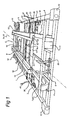
- the swivel frame for a rail vehicle is shown in the figures in its entirety by 1.
- the swivel frame 1 is designed for loading a container from a road vehicle onto a rail vehicle, and vice versa.
- the swivel frame 1 comprises a bottom frame 3 for fixing on an undercarriage of the rail vehicle (not shown).
- the swivel frame 1 has a top frame 5, which is pivotably connected by means of a pivot joint 18 to the bottom frame 3.
- a pivot joint 18 for example in the form of a roller race, ball race or the like, is known per se and will therefore not be described in any further detail.
- the bottom frame 3 has a longitudinal axis 14.
- the bottom frame 3 comprises a number of longitudinal beams 7, each extending substantially parallel to the longitudinal axis 14.
- the longitudinal beams 7 are connected by a number of transverse beams 8.
- Corner blocks 12 are fitted at the corners of the bottom frame 3.
- the corner blocks 12 are of ISO standard design, i.e. the corner blocks 12 are standardized corner castings.
- the corner castings 12 are detachably fixed on the undercarriage of the rail vehicle, for example by means of ISO locking pins ("twist locks").
- the bottom frame 3 with the longitudinal beams 7 and transverse beams 8 is self-supporting and connected only by means of the corner castings 12 to the rail vehicle.
- the bottom frame 3 is placed by means of the corner castings 12 on the undercarriage of the rail vehicle during transport.
- the weight of a container resting on the top frame 5 is transmitted by means of the longitudinal beams 7 and transverse beams 8 and the standardized corner castings 12 to the rail vehicle.
- the swivel frame 1 therewith forms a removable swap body, which fits as an adapter on a standard container piggyback wagon for rail transport.
- a transverse plate 9 is furthermore fitted between two transverse beams 8 at the position of the pivot joint 18.
- the bottom frame 3 has an arcuate part 10.
- Two stops 11 are fitted on the front side of the bottom frame 3. In the event of a collision, the stops 11 prevent a container accommodated on the swivel frame 1 from being able to shoot forward.
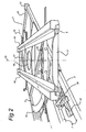
- the top frame 5 has a longitudinal axis 15.
- the top frame 5 can be swung between a swung-in and a swung-out position.
- the longitudinal axis 14 of the bottom frame 3 is substantially parallel to the longitudinal axis 15 of the top frame 5.
- said longitudinal axes 14,15 of the bottom frame 3 and the top frame 5 respectively intersect each other.
- the top frame 5 comprises two longitudinal bearers 16, each extending substantially parallel to the longitudinal axis 15.
- the longitudinal bearers 16 are connected to each other by means of transverse elements 17. Fitted between the longitudinal bearers 16 are a number of wheels 19, which can travel over the arcuate part 10 of the bottom frame 3.
- the swivel frame 1 comprises a locking mechanism 30, by means of which the top frame 5 can be locked in the swung-in position relative to the bottom frame 3.
- the locking mechanism 30 in this exemplary embodiment has a first swing-out lock, a second swing-out lock and a vertical lock. The locking mechanism 30 will now be explained in greater detail with reference to Figures 3a - 3e .
- the first swing-out lock of the locking mechanism 30 comprises a blocking element 32 which is connected to the bottom frame 3 so that it can pivot about a first pivot axis 35.
- the blocking element 32 can pivot or tumble about the pivot axis 35 between two positions. In the position shown in Figures 3a and 3b , the part of the blocking element 32 extending transversely inwards from the pivot axis 35 is tilted upwards slightly. This part forms a stop part having at its head end a stop 38 which can interact with a lug 23 on the longitudinal bearer 16 of the top frame 5. The top frame 5 is then locked.
- the centre of gravity of the blocking element 32 lies on the side of the pivot axis 35 facing away from the stop 38 - in this exemplary embodiment between the pivot axis 35 and the outermost longitudinal beam 7 of the bottom frame 3.
- the part of the blocking element 32 extending transversely outwards from the pivot axis 35 forms a counterweight.
- the blocking element 32 falls without external influence into the locked position shown in Figures 3a , 3b and 3e .
- an operating handle 33 is provided, which operating handle is connected to the bottom frame 3 so that it can pivot about a second pivot axis 36.
- the first and second pivot axes 35,36 run at a mutual distance and substantially parallel to each other.
- a securing member 41 is provided.
- the securing element 41 can assume a horizontal and a vertical position.
- the bottom frame 3 has a recess 40 (see Figure 3a ), in which a part of the operating handle 33 can be accommodated. After the operating handle 33 is lying in the recess 40, the securing member 41 can be placed upright over the end of the operating handle 33 accommodated in that recess 40.
- the second swing-out lock of the locking mechanism 30 comprises a rotation shaft or pivot pin 45, which is rotatably connected to the bottom frame 3.
- a locking member is fixed on the rotation shaft 45.
- the locking member comprises four locking strips 43, which are fixed on the rotation shaft 45 at a distance from each other.
- the rotation shaft 45 can be moved manually between two positions by means of the operating lever 47.
- the longitudinal bearers 16 of the top frame 5 are accommodated between the locking strips 43.
- the height of the locking strips 43 is such that their top edges 46 project above the underside of the top frame 5.
- the locking strips 43 each have a stop 44 which faces the longitudinal bearers 16.
- the stops 44 secure the top frame 5 in the swung-in position. By lowering the operating lever 47 - backwards - the locking strips 43 go into a position below the top frame 5. The stops 44 no longer retain the longitudinal bearers 16, so that the top frame 5 can swing out.
- the locking strips 43 are positioned in such a way that the locking strips 43 can assume the first locked position only if the top frame 5 is situated in the swung-in middle position.
- the top frame 5 is swung out to a greater or lesser extent from the middle position, it is impossible for the locking strips 43 to tilt upwards, owing to the fact that the top frame 5 is then in the way.
- the operating lever 47 is up, the top frame 5 is guaranteed to be locked.
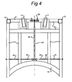
- the vertical lock of the locking mechanism 30 comprises a hook member 50 on the front side of the bottom frame 3 (see Figures 1 and 4 ).
- the hook member 50 is connected by means of a transmission mechanism 51 to the rotation shaft 45.
- the transmission mechanism 51 comprises a transmission strip 52, which extends substantially in the longitudinal direction of the bottom frame 3.
- the transmission strip 52 is pivotably fitted between the rotation shaft 45 and the hook element 50, in such a way that the hook member 50 moves forward when the operating lever 47 is pulled backwards. This therefore causes the hook member 50 to move towards the opened position.
- the transmission strip 52 has a transverse projection 53 (see Figure 5a ), which in the closed position of the hook member 50 rests against a transverse beam 8 of the bottom frame 3. As a result of this, the transmission strip 52 is elastically deformed, so that the hook member 50 is securely fixed in its closed position.
Landscapes
- Engineering & Computer Science (AREA)
- Transportation (AREA)
- Mechanical Engineering (AREA)
- Fittings On The Vehicle Exterior For Carrying Loads, And Devices For Holding Or Mounting Articles (AREA)
- Lock And Its Accessories (AREA)
Claims (16)
- Drehrahmen für ein Schienenfahrzeug, umfassend einen unteren Rahmen (3) zum Befestigen an einem Fahrgestell des Schienenfahrzeugs und einen oberen Rahmen (5) zum Aufnehmen eines Containers, wobei der obere Rahmen (5) derart mit dem unteren Rahmen (3) verbunden ist, dass er sich zwischen einer eingeschwenkten Position, in welcher der obere Rahmen (5) im Wesentlichen parallel zu dem unteren Rahmen (3) verläuft, und einer ausgeschwenkten Position, in welcher der obere Rahmen (5) in einem Winkel relativ zu dem unteren Rahmen (3) verläuft, drehen kann, wobei der untere Rahmen (3) mit etlichen Eckblöcken (12) versehen ist, welche lösbar an dem Fahrgestell des Schienenfahrzeugs befestigt werden können, wobei der Drehrahmen ferner einen Verriegelungsmechanismus (30) aufweist, welcher eine Verriegelungsposition aufweist, in welcher der obere Rahmen (5) in der eingeschwenkten Position relativ zu dem unteren Rahmen (3) verriegelt ist, und eine Freigabeposition aufweist, in welcher sich der obere Rahmen (5) aus seiner eingeschwenkten Position relativ zu dem unteren Rahmen (3) drehen kann,
dadurch gekennzeichnet, dass der Verriegelungsmechanismus (30) einen Satz von ersten Ausschwenkarretierungen, welche an beiden Seiten des oberen Rahmens (5) angeordnet sind, und einen Satz von zweiten Ausschwenkarretierungen, welche auch an beiden Seiten des oberen Rahmens (5) angeordnet sind, zum Verriegeln des oberen Rahmens (5) relativ zu dem unteren Rahmen (3) umfasst, wobei jede der Ausschwenkarretierungen eine Verriegelungsposition und eine Freigabeposition aufweist. - Drehrahmen nach Anspruch 1, dadurch gekennzeichnet, dass in der eingeschwenkten Position der obere Rahmen (5) relativ zu dem unteren Rahmen (3) verriegelt ist, wenn mindestens ein Satz von Verriegelungsmechanismen (30) in der Verriegelungsposition ist, und dass sich nur, wenn alle Sätze von Verriegelungsmechanismen (30) in der Freigabeposition sind, der obere Rahmen (5) aus seiner eingeschwenkten Position relativ zu dem unteren Rahmen (3) drehen kann.
- Drehrahmen nach Anspruch 1 oder 2, dadurch gekennzeichnet, dass jeder Verriegelungsmechanismus einen dem oberen Rahmen (5) gegenüberliegenden Anschlag (38; 44) umfasst, welcher mit einer Seite des oberen Rahmens (5) in der Verriegelungsposition zusammenwirkt.
- Drehrahmen nach Anspruch 1, wobei der untere Rahmen (3) in einer derartigen Art und Weise ausgestaltet ist, dass der untere Rahmen (3) nur mittels der Eckblöcke (12) an dem Fahrgestell des Schienenfahrzeugs befestigt werden kann.
- Drehrahmen nach Anspruch 1, wobei der Verriegelungsmechanismus (30) mit einem Blockierelement (32) versehen ist, welches sich um eine erste Drehachse (35) zwischen einer ersten Position und einer zweiten Position drehen kann, wobei die Positionen der Verriegelungsposition bzw. der Freigabeposition entsprechen, und wobei das Blockierelement einen Anschlag (38) aufweist, welcher in der ersten Position des Blockierelements (32) den oberen Rahmen (5) in der eingeschwenkten Position sichert.
- Drehrahmen nach Anspruch 5, wobei der Verriegelungsmechanismus (30) mit einem Bediengriff (33) versehen ist, welcher sich um eine zweite Drehachse (36) zwischen einer ersten Position und einer zweiten Position drehen kann, wobei die Positionen der Verriegelungsposition bzw. der Freigabeposition entsprechen, wobei die erste Drehachse (35) und die zweite Drehachse (36) in einem gegenseitigen Abstand und im Wesentlichen parallel zueinander verlaufen, und wobei das Blockierelement (32) mittels des Bediengriffs (33) bewegbar ist.
- Drehrahmen nach Anspruch 6, wobei die erste Position des Bediengriffs (33), welche der Verriegelungsposition entspricht, eine abgesenkte Position bildet, in welcher der Bediengriff unterhalb der horizontalen Ebene liegt, welche durch die Unterseite des oberen Rahmens (5) definiert wird, und wobei die zweite Position des Bediengriffs (33), welche der Freigabeposition entspricht, eine aufrechte Position bildet, in welcher der Bediengriff (33) relativ zu der Ebene nach oben hervorragt, und wobei das Blockierelement (32) von seiner ersten Position, welche der Verriegelungsposition entspricht, zu seiner zweiten Position, welche der Freigabeposition entspricht, durch Bewegen des Bediengriffs (33) von der abgesenkten Position zu der aufrechten Position bewegbar ist, und wobei der Bediengriff (33) durch den oberen Rahmen (5) von der aufrechten Position zu der abgesenkten Position gedrückt wird, wenn sich der obere Rahmen (5) von der eingeschwenkten Position zu der ausgeschwenkten Position dreht.
- Drehrahmen nach Anspruch 7, wobei der Schwerpunkt des Blockierelements (32) in einer derartigen Entfernung von der ersten Drehachse (35) liegt, dass sich das Blockierelement (32) unter dem Einfluss der Schwerkraft zu der Verriegelungsposition bewegt, wenn der Bediengriff (33) in der abgesenkten Position ist.
- Drehrahmen nach Anspruch 7 oder 8, wobei der untere Rahmen (3) mit einer Aussparung (40) zum Aufnehmen eines Teils des Bediengriffs (33) in der abgesenkten Position versehen ist, und wobei ein Teil des Bediengriffs (33), welcher in der Aussparung (40) aufgenommen ist, durch ein Sicherungselement (41) gesichert werden kann.
- Drehrahmen nach einem der vorhergehenden Ansprüche, wobei der Verriegelungsmechanismus (30) mit einer Drehwelle (45) mit einem daran befestigten Verriegelungselement (43) versehen ist, wobei sich die Drehwelle (45) im Wesentlichen quer relativ zu dem unteren Rahmen (3) erstreckt und sich zwischen einer ersten Position und einer zweiten Position drehen kann, wobei die Positionen der Verriegelungsposition bzw. der Freigabeposition entsprechen, wobei das Verriegelungselement (43) einen weiteren Anschlag (44) aufweist, welcher in der ersten Position der Drehwelle (45), welche der Verriegelungsposition entspricht, den oberen Rahmen (5) in der eingeschwenkten Position sichert.
- Drehrahmen nach Anspruch 10, wobei der obere Rahmen (5) mit zwei Längsträgern (7) versehen ist, welche in einem gegenseitigen Abstand und im Wesentlichen parallel zueinander angebracht sind, und wobei das Verriegelungselement (43) mindestens zwei Verriegelungsstreifen (43) umfasst, welche in der ersten Position des Verriegelungselements, welche der Verriegelungsposition entspricht, an beiden Seiten eines Längsträgers (7) in der eingeschwenkten Position des oberen Rahmens (5) nach oben hervorragen, und wobei sich mindestens ein Verriegelungsstreifen (43) bei einer Drehung der Drehwelle (45) aus der zweiten Position, welche der Freigabeposition entspricht, gegen einen Längsträger (7) bewegt, wenn sich der obere Rahmen zwischen der eingeschwenkten und ausgeschwenkten Position befindet, um zu verhindern, dass die Drehwelle (45) nach dem Ausschwenken von der eingeschwenkten Position zu der ersten Position drehbar ist.
- Drehrahmen nach Anspruch 10 oder 11, wobei der untere Rahmen (3) an einer Vorderseite davon mit einem Hakenelement (50) versehen ist, welches zwischen einer geschlossenen Position zum in Eingriff bringen eines auf dem oberen Rahmen (5) aufzunehmenden Containers und einer offenen Position gedreht werden kann, und wobei die Drehwelle (45) über einen Übertragungsmechanismus (51) mit dem Hakenelement (50) verbunden ist.
- Drehrahmen nach Anspruch 12, wobei der Übertragungsmechanismus (51) in einer derartigen Art und Weise ausgestaltet ist, dass, wenn sich die Drehwelle (45) dreht, sich das Hakenelement (50) in einer Richtung entgegengesetzt zu der Drehrichtung der Drehwelle (45) dreht.
- Schienenfahrzeug umfassend ein Fahrgestell, etliche Räder, welche drehbar mit dem Fahrgestell verbunden sind, und ferner einen Drehrahmen (1), welcher mit einem unteren Rahmen (3) für ein Befestigen an dem Fahrgestell und einem oberen Rahmen (5) zum Aufnehmen eines Containers versehen ist, wobei der obere Rahmen (5) derart mit dem unteren Rahmen (3) verbunden ist, dass er sich zwischen einer eingeschwenkten Position, in welcher der obere Rahmen (5) im Wesentlichen parallel zu dem unteren Rahmen (3) verläuft, und einer ausgeschwenkten Position, in welcher der obere Rahmen (5) in einem Winkel relativ zu dem unteren Rahmen (3) verläuft, drehen kann, wobei der untere Rahmen (3) mit etlichen Eckblöcken (12) versehen ist, welche lösbar an dem Fahrgestell des Schienenfahrzeugs befestigt werden können, wobei der Schwenkrahmen ferner einen Verriegelungsmechanismus (30) umfasst, welcher eine Verriegelungsposition aufweist, in welcher der obere Rahmen (5) in der eingeschwenkten Position relativ zu dem unteren Rahmen (3) verriegelt ist, und welcher eine Freigabeposition aufweist, in welcher sich der obere Rahmen (5) aus seiner eingeschwenkten Position relativ zu dem unteren Rahmen (3) drehen kann, dadurch gekennzeichnet, dass der Verriegelungsmechanismus (30) einen Satz von ersten Ausschwenkarretierungen, welche an beiden Seiten des oberen Rahmens (5) angeordnet sind, und einen Satz von zweiten Ausschwenkarretierungen, welche auch an beiden Seiten des oberen Rahmens (5) angeordnet sind, zum Verriegeln des oberen Rahmens (5) relativ zu dem unteren Rahmen (3) umfasst, wobei jede Ausschwenkarretierung eine Verriegelungsposition und eine Freigabeposition aufweist.
- Schienenfahrzeug nach Anspruch 14, wobei der untere Rahmen (3) im Wesentlichen nur mittels der Eckblöcke (12) an dem Fahrgestell des Schienenfahrzeugs befestigt ist.
- Schienenfahrzeug nach Anspruch 14 oder 15, wobei der Drehrahmen (1) mit einem Verriegelungsmechanismus (30) versehen ist, welcher eine Verriegelungsposition aufweist, in welcher der obere Rahmen (5) in der eingeschwenkten Position relativ zu dem unteren Rahmen (3) verriegelt ist, und welcher eine Freigabeposition aufweist, in welcher sich der obere Rahmen (5) aus seiner eingeschwenkten Position relativ zu dem unteren Rahmen (3) drehen kann.
Priority Applications (2)
| Application Number | Priority Date | Filing Date | Title |
|---|---|---|---|
| EP11169868.4A EP2374682B1 (de) | 2007-04-20 | 2008-04-18 | Drehrahmen und Schienenfahrzeug |
| PL11169868T PL2374682T3 (pl) | 2007-04-20 | 2008-04-18 | Rama obrotowa i pojazd szynowy |
Applications Claiming Priority (1)
| Application Number | Priority Date | Filing Date | Title |
|---|---|---|---|
| NL2000602A NL2000602C2 (nl) | 2007-04-20 | 2007-04-20 | Draaiframe, en railvoertuig. |
Related Child Applications (2)
| Application Number | Title | Priority Date | Filing Date |
|---|---|---|---|
| EP11169868.4A Division EP2374682B1 (de) | 2007-04-20 | 2008-04-18 | Drehrahmen und Schienenfahrzeug |
| EP11169868.4 Division-Into | 2011-06-14 |
Publications (3)
| Publication Number | Publication Date |
|---|---|
| EP1982891A1 EP1982891A1 (de) | 2008-10-22 |
| EP1982891B1 EP1982891B1 (de) | 2013-06-12 |
| EP1982891B9 true EP1982891B9 (de) | 2013-09-04 |
Family
ID=38787057
Family Applications (2)
| Application Number | Title | Priority Date | Filing Date |
|---|---|---|---|
| EP20080154826 Active EP1982891B9 (de) | 2007-04-20 | 2008-04-18 | Drehrahmen und Schienenfahrzeug |
| EP11169868.4A Active EP2374682B1 (de) | 2007-04-20 | 2008-04-18 | Drehrahmen und Schienenfahrzeug |
Family Applications After (1)
| Application Number | Title | Priority Date | Filing Date |
|---|---|---|---|
| EP11169868.4A Active EP2374682B1 (de) | 2007-04-20 | 2008-04-18 | Drehrahmen und Schienenfahrzeug |
Country Status (3)
| Country | Link |
|---|---|
| EP (2) | EP1982891B9 (de) |
| NL (1) | NL2000602C2 (de) |
| PL (1) | PL2374682T3 (de) |
Families Citing this family (7)
| Publication number | Priority date | Publication date | Assignee | Title |
|---|---|---|---|---|
| KR101404049B1 (ko) * | 2012-07-30 | 2014-06-10 | (주)범창종합기술 | 화차용 무동력 회전장치 |
| KR101404050B1 (ko) * | 2012-07-30 | 2014-06-10 | (주)범창종합기술 | 무동력 회전장치를 이용한 환적 시스템 |
| CN104527669B (zh) * | 2015-01-05 | 2017-06-06 | 中车齐齐哈尔车辆有限公司 | 锁定装置及具有其的驮背运输车 |
| RU177592U1 (ru) * | 2016-11-14 | 2018-03-01 | Акционерное Общество "Научно-Внедренческий Центр "Вагоны" | Вагон-платформа со съемным кузовом |
| CN107914719B (zh) * | 2017-11-09 | 2019-06-25 | 中车长江车辆有限公司 | 一种驼背运输车的底架 |
| CN111301449B (zh) * | 2020-02-28 | 2024-08-23 | 中车齐齐哈尔车辆有限公司 | 一种旋转装卸货的驮背运输系统 |
| CN112093301B (zh) * | 2020-09-29 | 2022-06-21 | 中车齐齐哈尔车辆有限公司 | 运车架及具有其的集装箱 |
Family Cites Families (4)
| Publication number | Priority date | Publication date | Assignee | Title |
|---|---|---|---|---|
| NL8800161A (nl) | 1988-01-25 | 1989-08-16 | Ark Bv De | Draaiplateau voor een railvoertuig. |
| NL193612C (nl) * | 1989-12-07 | 2000-04-04 | Ark Bv De | Vergrendelingsinrichting voor container. |
| EP0516586B1 (de) * | 1991-05-27 | 1995-01-25 | Tuchschmid Ag | Vorrichtung zur seitlichen Verriegelung eines Drehrahmens auf einem Bahnwagen |
| DE19747085A1 (de) * | 1997-10-24 | 1999-04-29 | Manfred Sirch | Transportvorrichtung für Container auf Eisenbahnwaggons |
-
2007
- 2007-04-20 NL NL2000602A patent/NL2000602C2/nl not_active IP Right Cessation
-
2008
- 2008-04-18 EP EP20080154826 patent/EP1982891B9/de active Active
- 2008-04-18 EP EP11169868.4A patent/EP2374682B1/de active Active
- 2008-04-18 PL PL11169868T patent/PL2374682T3/pl unknown
Also Published As
| Publication number | Publication date |
|---|---|
| EP1982891B1 (de) | 2013-06-12 |
| PL2374682T3 (pl) | 2018-10-31 |
| EP2374682A1 (de) | 2011-10-12 |
| EP2374682B1 (de) | 2018-01-17 |
| NL2000602C2 (nl) | 2008-10-24 |
| EP1982891A1 (de) | 2008-10-22 |
Similar Documents
| Publication | Publication Date | Title |
|---|---|---|
| EP1982891B9 (de) | Drehrahmen und Schienenfahrzeug | |
| JP5394382B2 (ja) | 運搬車両の基台上にコンテナを固定する装置 | |
| DK2848473T3 (en) | Lastbærer for mounting on a vehicle's rear end | |
| CN100488819C (zh) | 铁路货车 | |
| EP2723619B1 (de) | Trägervorrichtung für einen seitwärts verschiebbaren eisenbahnwaggon | |
| EP0790912B1 (de) | Vorrichtung zum entladen durch den boden | |
| HU221835B1 (hu) | Vasúti kocsi | |
| KR100191962B1 (ko) | 컨테이너를 픽업 및 이송시키는 캐리지 | |
| JPH0268263A (ja) | 鉄道貨車 | |
| RU2359855C1 (ru) | Накаточный башмак для восстановления на рельсовый путь аварийных вагонов поезда, способ пакетирования башмаков и устройство для реализации способа | |
| HU207819B (en) | Railway car for transporting and storing bulk materials | |
| US3272150A (en) | Freight transportation system | |
| CA1123669A (en) | Rail car door linkage | |
| EP0679566B1 (de) | Vorrichtung zum Verhindern des Nickschwingens von Rad-Schiene-Sattelschleppern während des Schienentransportes | |
| EP0431690A1 (de) | Verriegelungsvorrichtung für Container | |
| US3606043A (en) | Lock means for door operating mechanism | |
| US3677194A (en) | Unit load hold-down and mounting | |
| CS158392A3 (en) | Device for side securing of a wagon rotary frame | |
| CZ280260B6 (cs) | Zařízení k zajištění nosiče nákladu na otočném rámu kolejového vozu | |
| JP3775822B2 (ja) | レール運搬車輌用脱線防止装置 | |
| KR20140016525A (ko) | 화차용 무동력 회전장치 | |
| US741455A (en) | Load retaining and releasing means for vehicles. | |
| US1092055A (en) | Bank-car. | |
| US721323A (en) | Dumping-car. | |
| JPH06503786A (ja) | 取外し可能な鉄道貨車用ヘッドストック |
Legal Events
| Date | Code | Title | Description |
|---|---|---|---|
| PUAI | Public reference made under article 153(3) epc to a published international application that has entered the european phase |
Free format text: ORIGINAL CODE: 0009012 |
|
| AK | Designated contracting states |
Kind code of ref document: A1 Designated state(s): AT BE BG CH CY CZ DE DK EE ES FI FR GB GR HR HU IE IS IT LI LT LU LV MC MT NL NO PL PT RO SE SI SK TR |
|
| AX | Request for extension of the european patent |
Extension state: AL BA MK RS |
|
| 17P | Request for examination filed |
Effective date: 20090422 |
|
| AKX | Designation fees paid |
Designated state(s): AT BE BG CH CY CZ DE DK EE ES FI FR GB GR HR HU IE IS IT LI LT LU LV MC MT NL NO PL PT RO SE SI SK TR |
|
| 17Q | First examination report despatched |
Effective date: 20090615 |
|
| GRAP | Despatch of communication of intention to grant a patent |
Free format text: ORIGINAL CODE: EPIDOSNIGR1 |
|
| GRAP | Despatch of communication of intention to grant a patent |
Free format text: ORIGINAL CODE: EPIDOSNIGR1 |
|
| GRAS | Grant fee paid |
Free format text: ORIGINAL CODE: EPIDOSNIGR3 |
|
| GRAA | (expected) grant |
Free format text: ORIGINAL CODE: 0009210 |
|
| AK | Designated contracting states |
Kind code of ref document: B1 Designated state(s): AT BE BG CH CY CZ DE DK EE ES FI FR GB GR HR HU IE IS IT LI LT LU LV MC MT NL NO PL PT RO SE SI SK TR |
|
| REG | Reference to a national code |
Ref country code: GB Ref legal event code: FG4D |
|
| REG | Reference to a national code |
Ref country code: CH Ref legal event code: EP |
|
| REG | Reference to a national code |
Ref country code: AT Ref legal event code: REF Ref document number: 616574 Country of ref document: AT Kind code of ref document: T Effective date: 20130615 |
|
| REG | Reference to a national code |
Ref country code: IE Ref legal event code: FG4D |
|
| REG | Reference to a national code |
Ref country code: DE Ref legal event code: R096 Ref document number: 602008025252 Country of ref document: DE Effective date: 20130808 |
|
| REG | Reference to a national code |
Ref country code: NL Ref legal event code: T3 |
|
| REG | Reference to a national code |
Ref country code: CH Ref legal event code: NV Representative=s name: SAEGER AND PARTNER PATENT- UND RECHTSANWAELTE, CH |
|
| PG25 | Lapsed in a contracting state [announced via postgrant information from national office to epo] |
Ref country code: SE Free format text: LAPSE BECAUSE OF FAILURE TO SUBMIT A TRANSLATION OF THE DESCRIPTION OR TO PAY THE FEE WITHIN THE PRESCRIBED TIME-LIMIT Effective date: 20130612 Ref country code: LT Free format text: LAPSE BECAUSE OF FAILURE TO SUBMIT A TRANSLATION OF THE DESCRIPTION OR TO PAY THE FEE WITHIN THE PRESCRIBED TIME-LIMIT Effective date: 20130612 Ref country code: SI Free format text: LAPSE BECAUSE OF FAILURE TO SUBMIT A TRANSLATION OF THE DESCRIPTION OR TO PAY THE FEE WITHIN THE PRESCRIBED TIME-LIMIT Effective date: 20130612 Ref country code: NO Free format text: LAPSE BECAUSE OF FAILURE TO SUBMIT A TRANSLATION OF THE DESCRIPTION OR TO PAY THE FEE WITHIN THE PRESCRIBED TIME-LIMIT Effective date: 20130912 Ref country code: FI Free format text: LAPSE BECAUSE OF FAILURE TO SUBMIT A TRANSLATION OF THE DESCRIPTION OR TO PAY THE FEE WITHIN THE PRESCRIBED TIME-LIMIT Effective date: 20130612 Ref country code: ES Free format text: LAPSE BECAUSE OF FAILURE TO SUBMIT A TRANSLATION OF THE DESCRIPTION OR TO PAY THE FEE WITHIN THE PRESCRIBED TIME-LIMIT Effective date: 20130923 Ref country code: GR Free format text: LAPSE BECAUSE OF FAILURE TO SUBMIT A TRANSLATION OF THE DESCRIPTION OR TO PAY THE FEE WITHIN THE PRESCRIBED TIME-LIMIT Effective date: 20130913 |
|
| REG | Reference to a national code |
Ref country code: LT Ref legal event code: MG4D |
|
| PG25 | Lapsed in a contracting state [announced via postgrant information from national office to epo] |
Ref country code: HR Free format text: LAPSE BECAUSE OF FAILURE TO SUBMIT A TRANSLATION OF THE DESCRIPTION OR TO PAY THE FEE WITHIN THE PRESCRIBED TIME-LIMIT Effective date: 20130612 Ref country code: BG Free format text: LAPSE BECAUSE OF FAILURE TO SUBMIT A TRANSLATION OF THE DESCRIPTION OR TO PAY THE FEE WITHIN THE PRESCRIBED TIME-LIMIT Effective date: 20130912 |
|
| PG25 | Lapsed in a contracting state [announced via postgrant information from national office to epo] |
Ref country code: LV Free format text: LAPSE BECAUSE OF FAILURE TO SUBMIT A TRANSLATION OF THE DESCRIPTION OR TO PAY THE FEE WITHIN THE PRESCRIBED TIME-LIMIT Effective date: 20130612 |
|
| PG25 | Lapsed in a contracting state [announced via postgrant information from national office to epo] |
Ref country code: PT Free format text: LAPSE BECAUSE OF FAILURE TO SUBMIT A TRANSLATION OF THE DESCRIPTION OR TO PAY THE FEE WITHIN THE PRESCRIBED TIME-LIMIT Effective date: 20131014 Ref country code: IS Free format text: LAPSE BECAUSE OF FAILURE TO SUBMIT A TRANSLATION OF THE DESCRIPTION OR TO PAY THE FEE WITHIN THE PRESCRIBED TIME-LIMIT Effective date: 20131012 Ref country code: SK Free format text: LAPSE BECAUSE OF FAILURE TO SUBMIT A TRANSLATION OF THE DESCRIPTION OR TO PAY THE FEE WITHIN THE PRESCRIBED TIME-LIMIT Effective date: 20130612 Ref country code: EE Free format text: LAPSE BECAUSE OF FAILURE TO SUBMIT A TRANSLATION OF THE DESCRIPTION OR TO PAY THE FEE WITHIN THE PRESCRIBED TIME-LIMIT Effective date: 20130612 Ref country code: CZ Free format text: LAPSE BECAUSE OF FAILURE TO SUBMIT A TRANSLATION OF THE DESCRIPTION OR TO PAY THE FEE WITHIN THE PRESCRIBED TIME-LIMIT Effective date: 20130612 Ref country code: BE Free format text: LAPSE BECAUSE OF FAILURE TO SUBMIT A TRANSLATION OF THE DESCRIPTION OR TO PAY THE FEE WITHIN THE PRESCRIBED TIME-LIMIT Effective date: 20130612 |
|
| PG25 | Lapsed in a contracting state [announced via postgrant information from national office to epo] |
Ref country code: RO Free format text: LAPSE BECAUSE OF FAILURE TO SUBMIT A TRANSLATION OF THE DESCRIPTION OR TO PAY THE FEE WITHIN THE PRESCRIBED TIME-LIMIT Effective date: 20130612 Ref country code: PL Free format text: LAPSE BECAUSE OF FAILURE TO SUBMIT A TRANSLATION OF THE DESCRIPTION OR TO PAY THE FEE WITHIN THE PRESCRIBED TIME-LIMIT Effective date: 20130612 |
|
| PLBE | No opposition filed within time limit |
Free format text: ORIGINAL CODE: 0009261 |
|
| STAA | Information on the status of an ep patent application or granted ep patent |
Free format text: STATUS: NO OPPOSITION FILED WITHIN TIME LIMIT |
|
| PG25 | Lapsed in a contracting state [announced via postgrant information from national office to epo] |
Ref country code: DK Free format text: LAPSE BECAUSE OF FAILURE TO SUBMIT A TRANSLATION OF THE DESCRIPTION OR TO PAY THE FEE WITHIN THE PRESCRIBED TIME-LIMIT Effective date: 20130612 |
|
| 26N | No opposition filed |
Effective date: 20140313 |
|
| PG25 | Lapsed in a contracting state [announced via postgrant information from national office to epo] |
Ref country code: IT Free format text: LAPSE BECAUSE OF FAILURE TO SUBMIT A TRANSLATION OF THE DESCRIPTION OR TO PAY THE FEE WITHIN THE PRESCRIBED TIME-LIMIT Effective date: 20130612 |
|
| REG | Reference to a national code |
Ref country code: DE Ref legal event code: R097 Ref document number: 602008025252 Country of ref document: DE Effective date: 20140313 |
|
| PG25 | Lapsed in a contracting state [announced via postgrant information from national office to epo] |
Ref country code: MC Free format text: LAPSE BECAUSE OF FAILURE TO SUBMIT A TRANSLATION OF THE DESCRIPTION OR TO PAY THE FEE WITHIN THE PRESCRIBED TIME-LIMIT Effective date: 20130612 Ref country code: LU Free format text: LAPSE BECAUSE OF FAILURE TO SUBMIT A TRANSLATION OF THE DESCRIPTION OR TO PAY THE FEE WITHIN THE PRESCRIBED TIME-LIMIT Effective date: 20140418 |
|
| GBPC | Gb: european patent ceased through non-payment of renewal fee |
Effective date: 20140418 |
|
| REG | Reference to a national code |
Ref country code: IE Ref legal event code: MM4A |
|
| PG25 | Lapsed in a contracting state [announced via postgrant information from national office to epo] |
Ref country code: GB Free format text: LAPSE BECAUSE OF NON-PAYMENT OF DUE FEES Effective date: 20140418 |
|
| PG25 | Lapsed in a contracting state [announced via postgrant information from national office to epo] |
Ref country code: IE Free format text: LAPSE BECAUSE OF NON-PAYMENT OF DUE FEES Effective date: 20140418 |
|
| REG | Reference to a national code |
Ref country code: AT Ref legal event code: MM01 Ref document number: 616574 Country of ref document: AT Kind code of ref document: T Effective date: 20140418 |
|
| PG25 | Lapsed in a contracting state [announced via postgrant information from national office to epo] |
Ref country code: AT Free format text: LAPSE BECAUSE OF NON-PAYMENT OF DUE FEES Effective date: 20140418 |
|
| PG25 | Lapsed in a contracting state [announced via postgrant information from national office to epo] |
Ref country code: MT Free format text: LAPSE BECAUSE OF FAILURE TO SUBMIT A TRANSLATION OF THE DESCRIPTION OR TO PAY THE FEE WITHIN THE PRESCRIBED TIME-LIMIT Effective date: 20130612 |
|
| REG | Reference to a national code |
Ref country code: FR Ref legal event code: PLFP Year of fee payment: 9 |
|
| PG25 | Lapsed in a contracting state [announced via postgrant information from national office to epo] |
Ref country code: CY Free format text: LAPSE BECAUSE OF FAILURE TO SUBMIT A TRANSLATION OF THE DESCRIPTION OR TO PAY THE FEE WITHIN THE PRESCRIBED TIME-LIMIT Effective date: 20130612 |
|
| PGFP | Annual fee paid to national office [announced via postgrant information from national office to epo] |
Ref country code: NL Payment date: 20160426 Year of fee payment: 9 |
|
| PG25 | Lapsed in a contracting state [announced via postgrant information from national office to epo] |
Ref country code: TR Free format text: LAPSE BECAUSE OF FAILURE TO SUBMIT A TRANSLATION OF THE DESCRIPTION OR TO PAY THE FEE WITHIN THE PRESCRIBED TIME-LIMIT Effective date: 20130612 Ref country code: HU Free format text: LAPSE BECAUSE OF FAILURE TO SUBMIT A TRANSLATION OF THE DESCRIPTION OR TO PAY THE FEE WITHIN THE PRESCRIBED TIME-LIMIT; INVALID AB INITIO Effective date: 20080418 |
|
| PGFP | Annual fee paid to national office [announced via postgrant information from national office to epo] |
Ref country code: FR Payment date: 20160502 Year of fee payment: 9 |
|
| REG | Reference to a national code |
Ref country code: NL Ref legal event code: MM Effective date: 20170501 |
|
| REG | Reference to a national code |
Ref country code: FR Ref legal event code: ST Effective date: 20171229 |
|
| PG25 | Lapsed in a contracting state [announced via postgrant information from national office to epo] |
Ref country code: FR Free format text: LAPSE BECAUSE OF NON-PAYMENT OF DUE FEES Effective date: 20170502 Ref country code: NL Free format text: LAPSE BECAUSE OF NON-PAYMENT OF DUE FEES Effective date: 20170501 |
|
| PGFP | Annual fee paid to national office [announced via postgrant information from national office to epo] |
Ref country code: DE Payment date: 20250417 Year of fee payment: 18 |
|
| PGFP | Annual fee paid to national office [announced via postgrant information from national office to epo] |
Ref country code: CH Payment date: 20250501 Year of fee payment: 18 |