EP0679566B1 - Vorrichtung zum Verhindern des Nickschwingens von Rad-Schiene-Sattelschleppern während des Schienentransportes - Google Patents
Vorrichtung zum Verhindern des Nickschwingens von Rad-Schiene-Sattelschleppern während des Schienentransportes Download PDFInfo
- Publication number
- EP0679566B1 EP0679566B1 EP95830058A EP95830058A EP0679566B1 EP 0679566 B1 EP0679566 B1 EP 0679566B1 EP 95830058 A EP95830058 A EP 95830058A EP 95830058 A EP95830058 A EP 95830058A EP 0679566 B1 EP0679566 B1 EP 0679566B1
- Authority
- EP
- European Patent Office
- Prior art keywords
- flange
- frame
- supports
- semitrailer
- pivot
- Prior art date
- Legal status (The legal status is an assumption and is not a legal conclusion. Google has not performed a legal analysis and makes no representation as to the accuracy of the status listed.)
- Expired - Lifetime
Links
Images
Classifications
-
- B—PERFORMING OPERATIONS; TRANSPORTING
- B61—RAILWAYS
- B61D—BODY DETAILS OR KINDS OF RAILWAY VEHICLES
- B61D45/00—Means or devices for securing or supporting the cargo, including protection against shocks
- B61D45/001—Devices for fixing to walls or floors
- B61D45/004—Fixing semi-trailers
-
- B—PERFORMING OPERATIONS; TRANSPORTING
- B61—RAILWAYS
- B61D—BODY DETAILS OR KINDS OF RAILWAY VEHICLES
- B61D3/00—Wagons or vans
- B61D3/16—Wagons or vans adapted for carrying special loads
- B61D3/18—Wagons or vans adapted for carrying special loads for vehicles
- B61D3/182—Wagons or vans adapted for carrying special loads for vehicles specially adapted for heavy vehicles, e.g. public work vehicles, trucks, trailers
- B61D3/184—Wagons or vans adapted for carrying special loads for vehicles specially adapted for heavy vehicles, e.g. public work vehicles, trucks, trailers the heavy vehicles being of the trailer or semi-trailer type
Definitions
- the invention relates to an anti-pitching device for intermodal semitrailers (destined both for use on the road and for loading on railway cars), during transport on railway cars.
- the semitrailer comprises a vertical pivot projecting from a frontal part of the trailer frame, which pivot is associable with a fifth wheel of a hauling vehicle; the above-mentioned association provides a vehicle-trailer articulation necessary for transporting the semitrailer by road.
- a railway car exhibits means for fixing containers to the car, comprising spikes for blocks affording engagement holes for the spikes.
- railway cars are usually equipped for receiving various types of load, among which are semitrailers also equipped for road use and usual unwheeled containers.
- a special housing is provided for the semitrailer articulation pivot, while the back end of the semitrailer, though its wheels are housed in a special loading pit fashioned in the car floor, is free to oscillate and tilt, obeying the properties of the semitrailer suspension, when the car negotiates a curve in the railway track.
- Containers can be solidly constrained to the railway car by means of a system of spikes engaging in shaped holes in fixing blocks exhibited by the containers themselves.
- Anchoring the semitrailers in the loading pit has however proved to be effective, except where the width of said semitrailers is between 2.5 metres and 2.6 metres on lines not equipped to tolerate such measurements.
- the above drawback is due to the fact that the semitrailers, particularly if they are refrigeration-plant-equipped, or in any case wheeled trailers, tend to tilt during transport around curves, and their main sections are therefore liable to exceed the legally-set width limits for transport on certain lines.
- a further drawback is represented by the fact that with respect to the railway tracks the loading pit is higher than the fixing spikes for the containers: this means that containers loaded on to the cars (due to legal container height limits) have to be vertically shorter than would otherwise be possible, leading to a loss of transportable volume.
- the document FR-A-2534870 discloses an anti-pitching device for intermodal semitrailers during transport on a railway car, according to the preamble of claim 1.
- the railway car is provided with means for fixing a container, said means for fixing normally are constituted by spikes.
- the anti-pitching device comprises blocks affording engagement holes for the spikes, and further comprises four rigid supports bearing the blocks, which supports are rigidly constrained to the frame, and are distributed on the two opposite sides thereof. Two of said supports are located on a front part of the frame.
- the invention solves the problem by providing an anti-pitching device for intermodal semitrailers comprising rigid supports bearing fixing blocks of the semitrailer to the spikes of the railway car, arranged on two opposite sides of the car and conformed in such a way as to realize rigid connections between the semitrailer and the car which at least during the semitrailer's use as a road trailer, are positioned above the face of the frame associable to the fifth wheel of the vehicle hauling said semitrailer.
- the device of the invention affords the further advantage of permitting transport of larger-volume semitrailers, with consequent cost reductions.
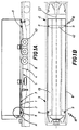
- figures 1A and 1B show that the invention largely consists in an anti-pitching device 18 for intermodal semitrailers 5 destined for use as road trailers but also transportable on railway cars 8, of the type provided with a loading pit 40.
- the semitrailer 5 comprises a vertical pivot 1 projectingly borne on a flat face 2 of a front part 3 of its frame 4, which front part 3 is destined to couple superposingly with a conventional fifth wheel located on the back of a road haulage vehicle (not illustrated) by means of said vertical pivot 1; this to allow articulation of the haulage vehicle and the semitrailer 5 during road use.
- the railway car 8 further comprises conventional fixing means, typical of such devices for constraining containers, provided with spikes 10 for blocks 9 (figures 3 and 9) exhibiting engagement holes 14 for said spikes 10.
- the anti-pitching device 18 comprises four rigid supports 11 bearing the blocks 9, which supports 11 are constrained to the frame 4 and distributed on the two opposite sides 19 thereof.
- Two of the four supports 11 are located on the front part 3 of the frame 4 while the remaining two supports 11 are located at the back 41 of the frame 4 on a reinforcing crossbar 42 on said frame 4.
- the front supports 11 are conformed such that the blocks 9, at least during road circulation of the semitrailer 5, can be removed totally above the face 2 of the frame 4.
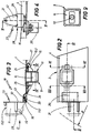
- Figure 3 shows in greater detail that the device 18 comprises a flange 15 for constraining the supports 11 during railway use of the device 18, which flange 15 can be removed from the face 2 of the frame 4 before the semitrailer 5 is used on the road, at least in cases where the supports 11 due to their mass cannot be stably lodged above the face 2 and removably from the frame 4.
- the solution in which the flange 15 is removable preferably comprises a horizontal pivot 16 borne by the frame 4 of the semitrailer 5, on which pivot 16 a first end 151 of the flange 15 for fixing the supports 11 is hinged such as to be rotatable from a first work position corresponding to the condition of the semitrailer 5 when transported on a railway car 8 in which a second end 152 of the flange 15 is associated to means 17 for blocking interacting between the flange 15 and the frame 4, to a rest position of the flange 15 corresponding to the semitrailer 5 condition when in road use, angularly rotated with respect to the pivot 16, in which the supports 11 are located above the face 2 of the frame 4 (figure 1) while the second end 152 of the flange 15 is correspondingly engaged by means 23 for holding said flange in the rest position.
- the flange 15 is further provided with a guide 33 for sliding along the pivot 16 such that the flange 15 can be translated (see figure 2) horizontally between a vertical plane 20 passing through the work position and the rest position of said flange 15 and a vertical plane 21 intermediate to the vertical plane 20 and the halfway line plane 22 of the railway car 8 at which position the flange 15 and the relative support 11 are contained internally of the outline of the semitrailer 5 during turning manoeuvres in road use.
- the angle of curvature of the maximum road turning manoeuvre (with the pivot 1 as the centre point) is indicated by R in figure 2.
- the means for blocking 17 comprise a bolt 24 shaped to fit into a through-cavity 25 made at the second end 152 of the flange 15.
- the bolt 24 is slidably borne by a guide 26 on the frame 4 having an interrupted central portion 27 in which, in said work position of the flange 15, the second end 152 of the flange 15 is inserted in alignment with the cavity 25, with the guide 26 staying engaged by drawing the bolt home through the guide 26 and the cavity 25.
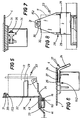
- the means for constraining 23 the flange 15 comprise a structure 28 for holding, together with the flange 15, the supports 11 in their rest position.
- the structure 28 is interconnected with the frame 4 and is provided with horizontal rest elements 29 having an angular profile and a flat vertical element 32 for horizontally contacting the supports 11.
- the rest elements 29 and the vertical element 32 are associated to a pawl 30 borne by the vertical element 32 superiorly to the rest elements 29 and rotatable about a horizontal pivot 31 oscillatingly about a stable equilibrium position.
- the pawl 30, when in a raised position, allows free transit of the supports 11 so that they can locate on the rest elements 29 of the structure 28, while it interferes, when in the lowered position, with the second end 152 of the flange 15 such as to prevent extraction of the supports 11 from the structure 28.
- Figures 3 and 5 show that the sliding guide 33 exhibits a much greater breadth than the pivot 16 such as to permit the flange 15 to be translatable with respect to the frame 4 perpendicularly to the rotation axis 161 of said pivot 16 to enable greater ease of insertion of the supports 11 on the rest elements 29.
- the device 18 further comprises an arm 34 hinged to the pivot 16 at said first end 151 of the flange 15.
- the arm 34 is hinged to the flange 15 at an intermediate pivot 36 (figure 7).
- the arm 34 (figure 7) permits of positioning the supports 11 in the rest position, starting from the work position of the flange 15, with two successive rotation movements, a first of which is described together by the flange 15 and the arm 34 which rotate together about the pivot 16; the second rotation movement is effected by the flange 15 which rotates with respect to the arm 34 after the arm 34 has reached a limit position determined by the strike of the arm 34 against the walls 43 of a shaped recess 44 afforded in the frame 4 of the semitrailer 5.
Landscapes
- Engineering & Computer Science (AREA)
- Transportation (AREA)
- Mechanical Engineering (AREA)
- Machines For Laying And Maintaining Railways (AREA)
- Vehicle Cleaning, Maintenance, Repair, Refitting, And Outriggers (AREA)
- Fittings On The Vehicle Exterior For Carrying Loads, And Devices For Holding Or Mounting Articles (AREA)
- Spinning Or Twisting Of Yarns (AREA)
- Replacing, Conveying, And Pick-Finding For Filamentary Materials (AREA)
- Handcart (AREA)
- Transition And Organic Metals Composition Catalysts For Addition Polymerization (AREA)
- Vehicle Body Suspensions (AREA)
- Auxiliary Methods And Devices For Loading And Unloading (AREA)
Claims (11)
- Vorrichtung zum Verhindern des Schwingens von Rad-Schiene-Sattelschleppern (5) während des Transportes auf einem Schienenwagen, wobei der Sattelschlepper (5) einen vertikalen Drehzapfen (1) enthält, der über den vorderen Teil des Sattelschlepperrahmens (4) vorsteht, wobei der Drehzapfen (1) mit einem fünften Rad eines Zugfahrzeuges verbindbar ist, um eine relative Gelenkverbindung zwischen dem besagten Sattelschlepper (5) und dem besagten Zugfahrzeug zu erhalten; der Schienenwagen (8) Mittel aufweist zur Befestigung eines Containers auf dem Schienenwagen, wobei die Befestigungsmittel aus Bolzen (10) bestehen; die Vorrichtung zum Verhindern des Schwingens Blöcke (9) enthält, die Aufnahmelöcher (14) für die Bolzen (10) aufweisen; die Vorrichtung (18) zum Verhindern des Schwingens weiterhin vier steife Stützen (11) enthält, die die Blöcke (9) tragen, wobei die Stützen (11) fest mit dem Rahmen (4) verbunden sind und auf dessen zwei gegenüberliegenden Seiten (19) verteilt angeordnet sind; zwei der besagten Stützen (11) in einem vorderen Teil (3) des Rahmens (4) angeordnet sind, und die Vorrichtung zum Verhindern des Schwingens dadurch gekennzeichnet ist, daß die besagten zwei Stützen (11) derart ausgebildet sind, daß die Blöcke (9), wenigstens während des Straßentransportes des Sattelschleppers (5), vollständig über die Oberfläche (2) des Rahmens (4) verlagert werden können.
- Vorrichtung nach Anspruch 1, dadurch gekennzeichnet, daß sie einen Flansch (15) enthält zur Befestigung der Stützen (11), wobei der Flansch (15) von der Oberfläche (2) des Rahmens (4) entfernt werden kann, bevor der Sattelschlepper (5) über die Straße transportiert wird.
- Vorrichtung nach Anspruch 1, dadurch gekennzeichnet, daß die besagten Stützen (11) lösbar an dem Rahmen (4) über der Oberfläche (2) befestigt sind.
- Vorrichtung nach Anspruch 2, dadurch gekennzeichnet, daß sie einen horizontalen, fest auf dem Rahmen (4) montierten Drehzapfen (16) aufweist, auf dem ein erstes Ende (151) des besagten Flansches (15) derart angelenkt ist, daß der besagte Flansch (15) gedreht werden kann aus einer ersten Stellung, das heißt, wenn der besagte Sattelschlepper (5) auf dem Schienenwagen (8) transportiert wird, wobei ein zweites Ende (152) des besagten Flansches (15) mit Feststellmitteln (17) verbunden ist, die zwischen dem Flansch (15) und dem Rahmen (4) wirken, in eine zweite Stellung, das heißt, wenn der besagte Sattelschlepper (5) auf der Straße transportiert wird, wobei der Flansch (15) um einen Winkel in Bezug auf den besagten horizontalen Drehzapfen (16) gedreht wird und wobei die besagten Stützen (11) oberhalb der Oberfläche (2) des Rahmens (4) angeordnet sind, während das besagte zweite Ende (152) durch Haltemittel (23) des besagten Flansches (15) in eine Ruhestellung gebracht wird.
- Vorrichtung nach Anspruch 4, dadurch gekennzeichnet, daß der besagte Flansch (15) mit einer Führung versehen ist (33), entlang welcher der besagte horizontale Drehzapfen (16) von einer ersten vertikalen Ebene (20), die besagte erste Stellung und die besagte zweite Stellung des Flansches (15) passierend, in eine zweite vertikale Ebene (21) gleitet, die zwischen der besagten ersten vertikalen Ebene (20) und einer Mittellinienebene des Schienenwagens (8) liegt, wobei der Flansch (15) und die Stütze (11) innerhalb einer Gesamtmassenaußenlinie des Sattelschleppers (5) in der zweiten vertikalen Ebene (21) enthalten sind, während Drehmanövrierbewegungen des Zugfahrzeuges bei der Straßenbenutzung des Sattelschleppers (5).
- Vorrichtung nach Anspruch 4, dadurch gekennzeichnet, daß die Feststellmittel (17) einen Bolzen (24) enthalten, der derart geformt ist, daß er in einen in dem zweiten Ende (152) des besagten Flansches (15) vorgesehenen Durchgangshohlraum (25) anbringbar ist, wobei der besagte Bolzen (24) durch eine Führung (26) verschiebbar getragen wird, die auf dem Rahmen (4) angebracht ist, und die besagte Führung (26) einen zentralen Anteil (27) enthält, in welchem bei der besagten ersten Stellung des Flansches (15) deren zweites Ende (152) in einer Linie in Bezug auf den Hohlraum (25) eingeführt ist, mit der Führung (26) in Eingriff stehend, da der Bolzen (24) durch die besagte Führung (26) und den besagten Hohlraum (25) zurückgezogen ist.
- Vorrichtung nach Anspruch 4, dadurch gekennzeichnet, daß die besagten Befestigungsmittel (23) des Flansches (15) eine Struktur (28) enthalten, um, zusammen mit dem Flansch (15), die Stützen (11) in der besagten zweiten Stellung zu halten, wobei die besagte Struktur (28) mit dem Rahmen (4) in Verbindung steht und mit horizontalen Auflageelementen (29) und einem vertikalen Element (32) zur horizontalen Kontaktverbindung mit den Stützen (11) versehen ist, die besagten Auflageelemente (29) und das vertikale Element (32) mit einem Sperriegel (30) verbunden ist, der von dem vertikalen Element (32) oberhalb des Auflageelementes (29) und um einen horizontalen Zapfen (31) derart drehbar getragen wird, daß der Sperriegel (30), wenn er sich in einer oberen Stellung befindet, die Anordnung der Stützen (11) auf dem Auflageelement (29) der Struktur (28) erlaubt, während der Sperriegel (30), wenn er sich in der unteren Stellung befindet, derart auf das besagte zweite Ende (152) des Flansches (15) einwirkt, daß ein Ausziehen der Stützen (11) aus der Struktur (28) verhindert wird.
- Vorrichtung nach Anspruch 5, dadurch gekennzeichnet, daß die Gleitführung (33) eine sehr viel größere Breite als der Drehzapfen (16) aufweist, um zu ermöglichen, daß der Flansch (15) in Bezug auf den Rahmen (4) rechtwinklig zu einer Drehachse (161) des besagten Drehzapfens (16) verschiebbar ist.
- Vorrichtung nach Anspruch 4 oder 5, dadurch gekennzeichnet, daß sie einen Arm (34) aufweist, der an dem Drehzapfen (16) an dem besagten ersten Ende (151) des Flansches (15) angelenkt ist und an dem Flansch (15) an einem Zwischenzapfen (36) angelenkt ist, wobei der besagte Arm (34) ermöglicht, daß die Stützen (11) in der besagten zweiten Stellung angeordnet werden können, ausgehend von der besagten ersten Stellung des Flansches (15), mit einer ersten Drehbewegung, die zusammen durch den Flansch (15) und den Arm (34) ausgeführt wird, welche zusammen um den Drehzapfen (16) drehen; gefolgt durch eine zweite Drehung, die durch den Flansch (15) erfolgt, der in Bezug auf den Arm (34) dreht, nachdem der Arm (34) eine Grenzstellung erreicht hat, die durch einen Verschiebeendanschlag der Arms (34) gegen den Rahmen (4) des Sattelschleppers (5) festgelegt wird.
- Vorrichtung nach Anspruch 7, dadurch gekennzeichnet, daß das besagte horizontale Auflageelement (29) als ein Winkelprofil ausgebildet ist.
- Vorrichtung nach Anspruch 7, dadurch gekennzeichnet, daß der besagte Sperriegel (30) durch den besagten horizontalen Zapfen (31) um eine stabile Gleichgewichtsstellung pendelbar getragen wird.
Priority Applications (1)
| Application Number | Priority Date | Filing Date | Title |
|---|---|---|---|
| SI9530017T SI0679566T1 (en) | 1994-04-28 | 1995-02-24 | An anti-pitching device for intermodal semitrailers during transport by rail |
Applications Claiming Priority (2)
| Application Number | Priority Date | Filing Date | Title |
|---|---|---|---|
| ITBO940180 | 1994-04-28 | ||
| IT94BO000180A ITBO940180A1 (it) | 1994-04-28 | 1994-04-28 | Dispositivo anticoricamento per semirimorchi intermodali durante il trasporto su carro ferroviario. |
Publications (2)
| Publication Number | Publication Date |
|---|---|
| EP0679566A1 EP0679566A1 (de) | 1995-11-02 |
| EP0679566B1 true EP0679566B1 (de) | 1997-04-23 |
Family
ID=11339744
Family Applications (1)
| Application Number | Title | Priority Date | Filing Date |
|---|---|---|---|
| EP95830058A Expired - Lifetime EP0679566B1 (de) | 1994-04-28 | 1995-02-24 | Vorrichtung zum Verhindern des Nickschwingens von Rad-Schiene-Sattelschleppern während des Schienentransportes |
Country Status (8)
| Country | Link |
|---|---|
| EP (1) | EP0679566B1 (de) |
| AT (1) | ATE152061T1 (de) |
| DE (1) | DE69500253T2 (de) |
| DK (1) | DK0679566T3 (de) |
| ES (1) | ES2104469T3 (de) |
| GR (1) | GR3024196T3 (de) |
| IT (1) | ITBO940180A1 (de) |
| SI (1) | SI0679566T1 (de) |
Families Citing this family (5)
| Publication number | Priority date | Publication date | Assignee | Title |
|---|---|---|---|---|
| GB2420331B (en) * | 2004-11-18 | 2008-03-19 | Robert Malcolm Ord | Intermodal trailer |
| WO2014189896A1 (en) * | 2013-05-20 | 2014-11-27 | Load Distribution Technologies LLC | Cambered frame system for intermodal rail cars |
| CN107878492A (zh) * | 2017-12-12 | 2018-04-06 | 山西聚鑫盛商贸有限公司 | 一种固定铁路货车与公路半挂车的锁闭连接装置 |
| CN112026632B (zh) * | 2020-09-28 | 2024-04-02 | 河北富华专用汽车制造有限公司 | 一种运材挂车自动卡紧装置 |
| CN114312684B (zh) * | 2022-01-14 | 2023-08-29 | 洛阳中集凌宇汽车有限公司 | 一种甩挂结构混凝土搅拌运输半挂车 |
Family Cites Families (6)
| Publication number | Priority date | Publication date | Assignee | Title |
|---|---|---|---|---|
| US3575118A (en) * | 1968-11-08 | 1971-04-13 | Pullman Inc | Multipurpose railroad car |
| FR2534870A1 (fr) * | 1982-10-20 | 1984-04-27 | Inge Trans Sa | Semi-remorque pour la coordination technique rail-route et wagon charge de cette semi-remorque |
| DE3367570D1 (en) * | 1983-11-22 | 1987-01-02 | Fruehauf France | Semi-trailers for rail and road traffic |
| US4844672A (en) * | 1988-04-20 | 1989-07-04 | Rosby Corporation | Interlocking adapter casting |
| DE9105054U1 (de) * | 1991-04-25 | 1991-06-13 | Waggonfabrik Talbot, 5100 Aachen, De | |
| DE9207500U1 (de) * | 1992-06-03 | 1992-07-30 | Waggonfabrik Talbot, 5100 Aachen, De |
-
1994
- 1994-04-28 IT IT94BO000180A patent/ITBO940180A1/it unknown
-
1995
- 1995-02-24 DE DE69500253T patent/DE69500253T2/de not_active Expired - Fee Related
- 1995-02-24 SI SI9530017T patent/SI0679566T1/xx unknown
- 1995-02-24 EP EP95830058A patent/EP0679566B1/de not_active Expired - Lifetime
- 1995-02-24 AT AT95830058T patent/ATE152061T1/de not_active IP Right Cessation
- 1995-02-24 DK DK95830058.4T patent/DK0679566T3/da active
- 1995-02-24 ES ES95830058T patent/ES2104469T3/es not_active Expired - Lifetime
-
1997
- 1997-07-23 GR GR970401842T patent/GR3024196T3/el unknown
Also Published As
| Publication number | Publication date |
|---|---|
| ES2104469T3 (es) | 1997-10-01 |
| DE69500253T2 (de) | 1997-11-20 |
| DK0679566T3 (da) | 1997-10-27 |
| EP0679566A1 (de) | 1995-11-02 |
| GR3024196T3 (en) | 1997-10-31 |
| DE69500253D1 (de) | 1997-05-28 |
| ATE152061T1 (de) | 1997-05-15 |
| ITBO940180A1 (it) | 1995-10-28 |
| ITBO940180A0 (it) | 1994-04-28 |
| SI0679566T1 (en) | 1999-02-28 |
Similar Documents
| Publication | Publication Date | Title |
|---|---|---|
| US4179997A (en) | Rail-highway intermodal freight carrier transport system | |
| US4685399A (en) | Intermodal transport | |
| CA2166757C (en) | Container support pedestal | |
| US4674929A (en) | Railroad car with chock block apparatus for securing vehicles being transported | |
| US5017064A (en) | Intermodal transport system | |
| US3984117A (en) | Locking device for freight carts | |
| NO176873C (no) | Jernbanegodsvogn | |
| SK378691A3 (en) | Wagon for loose material | |
| EP0869891B1 (de) | Eisenbahngüterwagen | |
| RU2282547C2 (ru) | Железнодорожная платформа с грузовой поворотной конструкцией для комбинированной железнодорожно-автомобильной перевозки либо одного полуприцепа, либо двух автотранспортных средств | |
| EP0679566B1 (de) | Vorrichtung zum Verhindern des Nickschwingens von Rad-Schiene-Sattelschleppern während des Schienentransportes | |
| HU214394B (hu) | Vasúti zsebeskocsi közúti félpótkocsik nem kísért forgalomban történő szállítására | |
| PL294312A1 (en) | Freight car | |
| US4948310A (en) | Rail vehicle for transporting road semi-trailers | |
| US3002636A (en) | Method of "piggie-back" transportation | |
| EP0209312B1 (de) | Transportsystem-Anpassungsvorrichtung | |
| US2015313A (en) | Tractor-trailer coupling device | |
| US3063386A (en) | Railway cars for transporting road semi-trailers | |
| US3272150A (en) | Freight transportation system | |
| EP1028881B1 (de) | Sattelkupplungsanordnung für ein auf gleisen verfahrbares fahrzeug | |
| US3431868A (en) | Cover for deck openings in railway flatcars | |
| US3416464A (en) | Mounting arrangement for demountable containers on railway cars | |
| GB2201928A (en) | A coupling device to be mounted on a railway bogie for coupling bimodal transport wagons suitably prearranged | |
| US4397601A (en) | Convertible rail-highway vehicle | |
| RU2110427C1 (ru) | Дорожно-рельсовая транспортная система |
Legal Events
| Date | Code | Title | Description |
|---|---|---|---|
| PUAI | Public reference made under article 153(3) epc to a published international application that has entered the european phase |
Free format text: ORIGINAL CODE: 0009012 |
|
| AK | Designated contracting states |
Kind code of ref document: A1 Designated state(s): AT BE CH DE DK ES FR GB GR IE LI LU MC NL PT SE |
|
| RAX | Requested extension states of the european patent have changed |
Free format text: LT PAYMENT 950309;SI PAYMENT 950309 |
|
| 17P | Request for examination filed |
Effective date: 19951222 |
|
| 17Q | First examination report despatched |
Effective date: 19960129 |
|
| GRAG | Despatch of communication of intention to grant |
Free format text: ORIGINAL CODE: EPIDOS AGRA |
|
| GRAH | Despatch of communication of intention to grant a patent |
Free format text: ORIGINAL CODE: EPIDOS IGRA |
|
| GRAH | Despatch of communication of intention to grant a patent |
Free format text: ORIGINAL CODE: EPIDOS IGRA |
|
| GRAA | (expected) grant |
Free format text: ORIGINAL CODE: 0009210 |
|
| AK | Designated contracting states |
Kind code of ref document: B1 Designated state(s): AT BE CH DE DK ES FR GB GR IE LI LU MC NL PT SE |
|
| AX | Request for extension of the european patent |
Free format text: LT PAYMENT 950309;SI PAYMENT 950309 |
|
| REF | Corresponds to: |
Ref document number: 152061 Country of ref document: AT Date of ref document: 19970515 Kind code of ref document: T |
|
| REG | Reference to a national code |
Ref country code: CH Ref legal event code: EP |
|
| REF | Corresponds to: |
Ref document number: 69500253 Country of ref document: DE Date of ref document: 19970528 |
|
| REG | Reference to a national code |
Ref country code: IE Ref legal event code: FG4D Free format text: 73612 |
|
| REG | Reference to a national code |
Ref country code: CH Ref legal event code: NV Representative=s name: BUGNION S.A. |
|
| ET | Fr: translation filed | ||
| REG | Reference to a national code |
Ref country code: GR Ref legal event code: FG4A Free format text: 3024196 |
|
| REG | Reference to a national code |
Ref country code: ES Ref legal event code: FG2A Ref document number: 2104469 Country of ref document: ES Kind code of ref document: T3 |
|
| REG | Reference to a national code |
Ref country code: DK Ref legal event code: T3 |
|
| REG | Reference to a national code |
Ref country code: PT Ref legal event code: SC4A Free format text: AVAILABILITY OF NATIONAL TRANSLATION Effective date: 19970715 |
|
| PGFP | Annual fee paid to national office [announced via postgrant information from national office to epo] |
Ref country code: IE Payment date: 19980220 Year of fee payment: 4 |
|
| PGFP | Annual fee paid to national office [announced via postgrant information from national office to epo] |
Ref country code: FR Payment date: 19980224 Year of fee payment: 4 |
|
| PGFP | Annual fee paid to national office [announced via postgrant information from national office to epo] |
Ref country code: SE Payment date: 19980225 Year of fee payment: 4 Ref country code: PT Payment date: 19980225 Year of fee payment: 4 Ref country code: DK Payment date: 19980225 Year of fee payment: 4 Ref country code: AT Payment date: 19980225 Year of fee payment: 4 |
|
| PGFP | Annual fee paid to national office [announced via postgrant information from national office to epo] |
Ref country code: ES Payment date: 19980226 Year of fee payment: 4 |
|
| PGFP | Annual fee paid to national office [announced via postgrant information from national office to epo] |
Ref country code: GR Payment date: 19980227 Year of fee payment: 4 |
|
| PLBE | No opposition filed within time limit |
Free format text: ORIGINAL CODE: 0009261 |
|
| STAA | Information on the status of an ep patent application or granted ep patent |
Free format text: STATUS: NO OPPOSITION FILED WITHIN TIME LIMIT |
|
| PGFP | Annual fee paid to national office [announced via postgrant information from national office to epo] |
Ref country code: LU Payment date: 19980302 Year of fee payment: 4 Ref country code: DE Payment date: 19980302 Year of fee payment: 4 |
|
| 26N | No opposition filed | ||
| PGFP | Annual fee paid to national office [announced via postgrant information from national office to epo] |
Ref country code: BE Payment date: 19980417 Year of fee payment: 4 |
|
| PG25 | Lapsed in a contracting state [announced via postgrant information from national office to epo] |
Ref country code: MC Free format text: LAPSE BECAUSE OF NON-PAYMENT OF DUE FEES Effective date: 19980831 |
|
| LTIE | Lt: invalidation of european patent or patent extension | ||
| PG25 | Lapsed in a contracting state [announced via postgrant information from national office to epo] |
Ref country code: LU Free format text: LAPSE BECAUSE OF NON-PAYMENT OF DUE FEES Effective date: 19990224 Ref country code: IE Free format text: LAPSE BECAUSE OF NON-PAYMENT OF DUE FEES Effective date: 19990224 Ref country code: GB Free format text: LAPSE BECAUSE OF NON-PAYMENT OF DUE FEES Effective date: 19990224 Ref country code: AT Free format text: LAPSE BECAUSE OF NON-PAYMENT OF DUE FEES Effective date: 19990224 |
|
| PG25 | Lapsed in a contracting state [announced via postgrant information from national office to epo] |
Ref country code: SE Free format text: LAPSE BECAUSE OF NON-PAYMENT OF DUE FEES Effective date: 19990225 Ref country code: ES Free format text: THE PATENT HAS BEEN ANNULLED BY A DECISION OF A NATIONAL AUTHORITY Effective date: 19990225 |
|
| PG25 | Lapsed in a contracting state [announced via postgrant information from national office to epo] |
Ref country code: LI Free format text: LAPSE BECAUSE OF NON-PAYMENT OF DUE FEES Effective date: 19990228 Ref country code: GR Free format text: LAPSE BECAUSE OF NON-PAYMENT OF DUE FEES Effective date: 19990228 Ref country code: CH Free format text: LAPSE BECAUSE OF NON-PAYMENT OF DUE FEES Effective date: 19990228 Ref country code: BE Free format text: LAPSE BECAUSE OF NON-PAYMENT OF DUE FEES Effective date: 19990228 |
|
| PG25 | Lapsed in a contracting state [announced via postgrant information from national office to epo] |
Ref country code: DK Free format text: LAPSE BECAUSE OF NON-PAYMENT OF DUE FEES Effective date: 19990301 |
|
| BERE | Be: lapsed |
Owner name: E. BARTOLETTI S.P.A. Effective date: 19990228 |
|
| PG25 | Lapsed in a contracting state [announced via postgrant information from national office to epo] |
Ref country code: PT Free format text: LAPSE BECAUSE OF NON-PAYMENT OF DUE FEES Effective date: 19990831 |
|
| PG25 | Lapsed in a contracting state [announced via postgrant information from national office to epo] |
Ref country code: NL Free format text: LAPSE BECAUSE OF NON-PAYMENT OF DUE FEES Effective date: 19990901 |
|
| GBPC | Gb: european patent ceased through non-payment of renewal fee |
Effective date: 19990224 |
|
| REG | Reference to a national code |
Ref country code: CH Ref legal event code: PL |
|
| PG25 | Lapsed in a contracting state [announced via postgrant information from national office to epo] |
Ref country code: FR Free format text: LAPSE BECAUSE OF NON-PAYMENT OF DUE FEES Effective date: 19991029 |
|
| EUG | Se: european patent has lapsed |
Ref document number: 95830058.4 |
|
| PG25 | Lapsed in a contracting state [announced via postgrant information from national office to epo] |
Ref country code: DE Free format text: LAPSE BECAUSE OF NON-PAYMENT OF DUE FEES Effective date: 19991201 |
|
| REG | Reference to a national code |
Ref country code: FR Ref legal event code: ST |
|
| REG | Reference to a national code |
Ref country code: PT Ref legal event code: MM4A Free format text: LAPSE DUE TO NON-PAYMENT OF FEES Effective date: 19990831 |
|
| REG | Reference to a national code |
Ref country code: DK Ref legal event code: EBP |
|
| REG | Reference to a national code |
Ref country code: ES Ref legal event code: FD2A Effective date: 20010604 |