EP0679566B1 - An anti-pitching device for intermodal semitrailers during transport by rail - Google Patents
An anti-pitching device for intermodal semitrailers during transport by rail Download PDFInfo
- Publication number
- EP0679566B1 EP0679566B1 EP95830058A EP95830058A EP0679566B1 EP 0679566 B1 EP0679566 B1 EP 0679566B1 EP 95830058 A EP95830058 A EP 95830058A EP 95830058 A EP95830058 A EP 95830058A EP 0679566 B1 EP0679566 B1 EP 0679566B1
- Authority
- EP
- European Patent Office
- Prior art keywords
- flange
- frame
- supports
- semitrailer
- pivot
- Prior art date
- Legal status (The legal status is an assumption and is not a legal conclusion. Google has not performed a legal analysis and makes no representation as to the accuracy of the status listed.)
- Expired - Lifetime
Links
Images
Classifications
-
- B—PERFORMING OPERATIONS; TRANSPORTING
- B61—RAILWAYS
- B61D—BODY DETAILS OR KINDS OF RAILWAY VEHICLES
- B61D45/00—Means or devices for securing or supporting the cargo, including protection against shocks
- B61D45/001—Devices for fixing to walls or floors
- B61D45/004—Fixing semi-trailers
-
- B—PERFORMING OPERATIONS; TRANSPORTING
- B61—RAILWAYS
- B61D—BODY DETAILS OR KINDS OF RAILWAY VEHICLES
- B61D3/00—Wagons or vans
- B61D3/16—Wagons or vans adapted for carrying special loads
- B61D3/18—Wagons or vans adapted for carrying special loads for vehicles
- B61D3/182—Wagons or vans adapted for carrying special loads for vehicles specially adapted for heavy vehicles, e.g. public work vehicles, trucks, trailers
- B61D3/184—Wagons or vans adapted for carrying special loads for vehicles specially adapted for heavy vehicles, e.g. public work vehicles, trucks, trailers the heavy vehicles being of the trailer or semi-trailer type
Definitions
- the invention relates to an anti-pitching device for intermodal semitrailers (destined both for use on the road and for loading on railway cars), during transport on railway cars.
- the semitrailer comprises a vertical pivot projecting from a frontal part of the trailer frame, which pivot is associable with a fifth wheel of a hauling vehicle; the above-mentioned association provides a vehicle-trailer articulation necessary for transporting the semitrailer by road.
- a railway car exhibits means for fixing containers to the car, comprising spikes for blocks affording engagement holes for the spikes.
- railway cars are usually equipped for receiving various types of load, among which are semitrailers also equipped for road use and usual unwheeled containers.
- a special housing is provided for the semitrailer articulation pivot, while the back end of the semitrailer, though its wheels are housed in a special loading pit fashioned in the car floor, is free to oscillate and tilt, obeying the properties of the semitrailer suspension, when the car negotiates a curve in the railway track.
- Containers can be solidly constrained to the railway car by means of a system of spikes engaging in shaped holes in fixing blocks exhibited by the containers themselves.
- Anchoring the semitrailers in the loading pit has however proved to be effective, except where the width of said semitrailers is between 2.5 metres and 2.6 metres on lines not equipped to tolerate such measurements.
- the above drawback is due to the fact that the semitrailers, particularly if they are refrigeration-plant-equipped, or in any case wheeled trailers, tend to tilt during transport around curves, and their main sections are therefore liable to exceed the legally-set width limits for transport on certain lines.
- a further drawback is represented by the fact that with respect to the railway tracks the loading pit is higher than the fixing spikes for the containers: this means that containers loaded on to the cars (due to legal container height limits) have to be vertically shorter than would otherwise be possible, leading to a loss of transportable volume.
- the document FR-A-2534870 discloses an anti-pitching device for intermodal semitrailers during transport on a railway car, according to the preamble of claim 1.
- the railway car is provided with means for fixing a container, said means for fixing normally are constituted by spikes.
- the anti-pitching device comprises blocks affording engagement holes for the spikes, and further comprises four rigid supports bearing the blocks, which supports are rigidly constrained to the frame, and are distributed on the two opposite sides thereof. Two of said supports are located on a front part of the frame.
- the invention solves the problem by providing an anti-pitching device for intermodal semitrailers comprising rigid supports bearing fixing blocks of the semitrailer to the spikes of the railway car, arranged on two opposite sides of the car and conformed in such a way as to realize rigid connections between the semitrailer and the car which at least during the semitrailer's use as a road trailer, are positioned above the face of the frame associable to the fifth wheel of the vehicle hauling said semitrailer.
- the device of the invention affords the further advantage of permitting transport of larger-volume semitrailers, with consequent cost reductions.
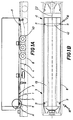
- figures 1A and 1B show that the invention largely consists in an anti-pitching device 18 for intermodal semitrailers 5 destined for use as road trailers but also transportable on railway cars 8, of the type provided with a loading pit 40.
- the semitrailer 5 comprises a vertical pivot 1 projectingly borne on a flat face 2 of a front part 3 of its frame 4, which front part 3 is destined to couple superposingly with a conventional fifth wheel located on the back of a road haulage vehicle (not illustrated) by means of said vertical pivot 1; this to allow articulation of the haulage vehicle and the semitrailer 5 during road use.
- the railway car 8 further comprises conventional fixing means, typical of such devices for constraining containers, provided with spikes 10 for blocks 9 (figures 3 and 9) exhibiting engagement holes 14 for said spikes 10.
- the anti-pitching device 18 comprises four rigid supports 11 bearing the blocks 9, which supports 11 are constrained to the frame 4 and distributed on the two opposite sides 19 thereof.
- Two of the four supports 11 are located on the front part 3 of the frame 4 while the remaining two supports 11 are located at the back 41 of the frame 4 on a reinforcing crossbar 42 on said frame 4.
- the front supports 11 are conformed such that the blocks 9, at least during road circulation of the semitrailer 5, can be removed totally above the face 2 of the frame 4.
- Figure 3 shows in greater detail that the device 18 comprises a flange 15 for constraining the supports 11 during railway use of the device 18, which flange 15 can be removed from the face 2 of the frame 4 before the semitrailer 5 is used on the road, at least in cases where the supports 11 due to their mass cannot be stably lodged above the face 2 and removably from the frame 4.
- the solution in which the flange 15 is removable preferably comprises a horizontal pivot 16 borne by the frame 4 of the semitrailer 5, on which pivot 16 a first end 151 of the flange 15 for fixing the supports 11 is hinged such as to be rotatable from a first work position corresponding to the condition of the semitrailer 5 when transported on a railway car 8 in which a second end 152 of the flange 15 is associated to means 17 for blocking interacting between the flange 15 and the frame 4, to a rest position of the flange 15 corresponding to the semitrailer 5 condition when in road use, angularly rotated with respect to the pivot 16, in which the supports 11 are located above the face 2 of the frame 4 (figure 1) while the second end 152 of the flange 15 is correspondingly engaged by means 23 for holding said flange in the rest position.
- the flange 15 is further provided with a guide 33 for sliding along the pivot 16 such that the flange 15 can be translated (see figure 2) horizontally between a vertical plane 20 passing through the work position and the rest position of said flange 15 and a vertical plane 21 intermediate to the vertical plane 20 and the halfway line plane 22 of the railway car 8 at which position the flange 15 and the relative support 11 are contained internally of the outline of the semitrailer 5 during turning manoeuvres in road use.
- the angle of curvature of the maximum road turning manoeuvre (with the pivot 1 as the centre point) is indicated by R in figure 2.
- the means for blocking 17 comprise a bolt 24 shaped to fit into a through-cavity 25 made at the second end 152 of the flange 15.
- the bolt 24 is slidably borne by a guide 26 on the frame 4 having an interrupted central portion 27 in which, in said work position of the flange 15, the second end 152 of the flange 15 is inserted in alignment with the cavity 25, with the guide 26 staying engaged by drawing the bolt home through the guide 26 and the cavity 25.
- the means for constraining 23 the flange 15 comprise a structure 28 for holding, together with the flange 15, the supports 11 in their rest position.
- the structure 28 is interconnected with the frame 4 and is provided with horizontal rest elements 29 having an angular profile and a flat vertical element 32 for horizontally contacting the supports 11.
- the rest elements 29 and the vertical element 32 are associated to a pawl 30 borne by the vertical element 32 superiorly to the rest elements 29 and rotatable about a horizontal pivot 31 oscillatingly about a stable equilibrium position.
- the pawl 30, when in a raised position, allows free transit of the supports 11 so that they can locate on the rest elements 29 of the structure 28, while it interferes, when in the lowered position, with the second end 152 of the flange 15 such as to prevent extraction of the supports 11 from the structure 28.
- Figures 3 and 5 show that the sliding guide 33 exhibits a much greater breadth than the pivot 16 such as to permit the flange 15 to be translatable with respect to the frame 4 perpendicularly to the rotation axis 161 of said pivot 16 to enable greater ease of insertion of the supports 11 on the rest elements 29.
- the device 18 further comprises an arm 34 hinged to the pivot 16 at said first end 151 of the flange 15.
- the arm 34 is hinged to the flange 15 at an intermediate pivot 36 (figure 7).
- the arm 34 (figure 7) permits of positioning the supports 11 in the rest position, starting from the work position of the flange 15, with two successive rotation movements, a first of which is described together by the flange 15 and the arm 34 which rotate together about the pivot 16; the second rotation movement is effected by the flange 15 which rotates with respect to the arm 34 after the arm 34 has reached a limit position determined by the strike of the arm 34 against the walls 43 of a shaped recess 44 afforded in the frame 4 of the semitrailer 5.
Abstract
Description
- The invention relates to an anti-pitching device for intermodal semitrailers (destined both for use on the road and for loading on railway cars), during transport on railway cars.
- The semitrailer comprises a vertical pivot projecting from a frontal part of the trailer frame, which pivot is associable with a fifth wheel of a hauling vehicle; the above-mentioned association provides a vehicle-trailer articulation necessary for transporting the semitrailer by road. A railway car exhibits means for fixing containers to the car, comprising spikes for blocks affording engagement holes for the spikes.
- Railway cars are usually equipped for receiving various types of load, among which are semitrailers also equipped for road use and usual unwheeled containers.
- To fix the front of the semitrailers to the railway car a special housing is provided for the semitrailer articulation pivot, while the back end of the semitrailer, though its wheels are housed in a special loading pit fashioned in the car floor, is free to oscillate and tilt, obeying the properties of the semitrailer suspension, when the car negotiates a curve in the railway track.
- Containers, on the other hand, can be solidly constrained to the railway car by means of a system of spikes engaging in shaped holes in fixing blocks exhibited by the containers themselves.
- Anchoring the semitrailers in the loading pit has however proved to be effective, except where the width of said semitrailers is between 2.5 metres and 2.6 metres on lines not equipped to tolerate such measurements. The above drawback is due to the fact that the semitrailers, particularly if they are refrigeration-plant-equipped, or in any case wheeled trailers, tend to tilt during transport around curves, and their main sections are therefore liable to exceed the legally-set width limits for transport on certain lines.
- A further drawback is represented by the fact that with respect to the railway tracks the loading pit is higher than the fixing spikes for the containers: this means that containers loaded on to the cars (due to legal container height limits) have to be vertically shorter than would otherwise be possible, leading to a loss of transportable volume.
- The document FR-A-2534870 discloses an anti-pitching device for intermodal semitrailers during transport on a railway car, according to the preamble of
claim 1. - The railway car is provided with means for fixing a container, said means for fixing normally are constituted by spikes.
- The anti-pitching device comprises blocks affording engagement holes for the spikes, and further comprises four rigid supports bearing the blocks, which supports are rigidly constrained to the frame, and are distributed on the two opposite sides thereof. Two of said supports are located on a front part of the frame.
- The aim of the present invention, as it is characterised in the claims that follow, is to obviate the above-described drawbacks.
- The invention solves the problem by providing an anti-pitching device for intermodal semitrailers comprising rigid supports bearing fixing blocks of the semitrailer to the spikes of the railway car, arranged on two opposite sides of the car and conformed in such a way as to realize rigid connections between the semitrailer and the car which at least during the semitrailer's use as a road trailer, are positioned above the face of the frame associable to the fifth wheel of the vehicle hauling said semitrailer.
- The fundamental advantages obtained by means of the present invention essentially consist in the fact of obviating the need for a loading pit in the car, and resultingly enabling all types of road semitrailer to be carried on railway cars regardless of limitations connected with load size and dimensions.
- The device of the invention affords the further advantage of permitting transport of larger-volume semitrailers, with consequent cost reductions.
- Further characteristics and advantages of the present invention will better emerge from the detailed description that follows, of an embodiment of the invention, illustrated in the form of a non-limiting example in the accompanying drawings, in which:
- figures 1A and 1B illustrate, according to respectively a vertical view and a plan view from above, an intermodal semitrailer arranged on a railway car and provided with fixing devices according to the invention;
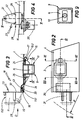
- figure 2 is an enlarged scale of a plan view from above of the device according to the invention, indicated by X in figure 1A;
- figure 3 shows a section of the device according to line III-III of figure 2;
- figure 4 is a frontal view of the device of figure 3;
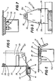
- figure 5 is an enlarged scale view of a section of the device of figure 2, made according to line V-V;
- figure 6 is an enlarged scale view of a section of the device of figure 2, made according to line VI-VI;
- figure 7 is an enlarged scale view of a section of the device of figure 2 according to line VII-VII;
- figure 8 is an enlarged-scale view of a view of the device of figure 3 seen from point D;
- figure 9 is an enlarged view of a detail of figure 3, sectioned according to line IX-IX.
- With reference to the enclosed drawings, figures 1A and 1B show that the invention largely consists in an
anti-pitching device 18 for intermodal semitrailers 5 destined for use as road trailers but also transportable on railway cars 8, of the type provided with aloading pit 40. - The semitrailer 5 comprises a
vertical pivot 1 projectingly borne on aflat face 2 of afront part 3 of itsframe 4, whichfront part 3 is destined to couple superposingly with a conventional fifth wheel located on the back of a road haulage vehicle (not illustrated) by means of saidvertical pivot 1; this to allow articulation of the haulage vehicle and the semitrailer 5 during road use. - The railway car 8 further comprises conventional fixing means, typical of such devices for constraining containers, provided with
spikes 10 for blocks 9 (figures 3 and 9) exhibitingengagement holes 14 for saidspikes 10. - The
anti-pitching device 18 comprises fourrigid supports 11 bearing theblocks 9, which supports 11 are constrained to theframe 4 and distributed on the twoopposite sides 19 thereof. - Two of the four
supports 11 are located on thefront part 3 of theframe 4 while the remaining twosupports 11 are located at theback 41 of theframe 4 on a reinforcingcrossbar 42 on saidframe 4. - The
front supports 11 are conformed such that theblocks 9, at least during road circulation of the semitrailer 5, can be removed totally above theface 2 of theframe 4. - Figure 3 shows in greater detail that the
device 18 comprises aflange 15 for constraining thesupports 11 during railway use of thedevice 18, whichflange 15 can be removed from theface 2 of theframe 4 before the semitrailer 5 is used on the road, at least in cases where the supports 11 due to their mass cannot be stably lodged above theface 2 and removably from theframe 4. - The solution in which the
flange 15 is removable preferably comprises ahorizontal pivot 16 borne by theframe 4 of the semitrailer 5, on which pivot 16 afirst end 151 of theflange 15 for fixing thesupports 11 is hinged such as to be rotatable from a first work position corresponding to the condition of the semitrailer 5 when transported on a railway car 8 in which asecond end 152 of theflange 15 is associated to means 17 for blocking interacting between theflange 15 and theframe 4, to a rest position of theflange 15 corresponding to the semitrailer 5 condition when in road use, angularly rotated with respect to thepivot 16, in which thesupports 11 are located above theface 2 of the frame 4 (figure 1) while thesecond end 152 of theflange 15 is correspondingly engaged bymeans 23 for holding said flange in the rest position. - The
flange 15 is further provided with aguide 33 for sliding along thepivot 16 such that theflange 15 can be translated (see figure 2) horizontally between avertical plane 20 passing through the work position and the rest position of saidflange 15 and avertical plane 21 intermediate to thevertical plane 20 and thehalfway line plane 22 of the railway car 8 at which position theflange 15 and therelative support 11 are contained internally of the outline of the semitrailer 5 during turning manoeuvres in road use. The angle of curvature of the maximum road turning manoeuvre (with thepivot 1 as the centre point) is indicated by R in figure 2. - In figure 6 it can be seen that the means for blocking 17 comprise a
bolt 24 shaped to fit into a through-cavity 25 made at thesecond end 152 of theflange 15. Thebolt 24 is slidably borne by aguide 26 on theframe 4 having an interruptedcentral portion 27 in which, in said work position of theflange 15, thesecond end 152 of theflange 15 is inserted in alignment with thecavity 25, with theguide 26 staying engaged by drawing the bolt home through theguide 26 and thecavity 25. - The means for constraining 23 the
flange 15 comprise astructure 28 for holding, together with theflange 15, the supports 11 in their rest position. - The
structure 28 is interconnected with theframe 4 and is provided withhorizontal rest elements 29 having an angular profile and a flatvertical element 32 for horizontally contacting thesupports 11. - The
rest elements 29 and the vertical element 32 (figure 8) are associated to apawl 30 borne by thevertical element 32 superiorly to therest elements 29 and rotatable about ahorizontal pivot 31 oscillatingly about a stable equilibrium position. - The
pawl 30, when in a raised position, allows free transit of thesupports 11 so that they can locate on therest elements 29 of thestructure 28, while it interferes, when in the lowered position, with thesecond end 152 of theflange 15 such as to prevent extraction of thesupports 11 from thestructure 28. - Figures 3 and 5 show that the
sliding guide 33 exhibits a much greater breadth than thepivot 16 such as to permit theflange 15 to be translatable with respect to theframe 4 perpendicularly to therotation axis 161 of saidpivot 16 to enable greater ease of insertion of thesupports 11 on therest elements 29. - Preferably the
device 18 further comprises anarm 34 hinged to thepivot 16 at saidfirst end 151 of theflange 15. Thearm 34 is hinged to theflange 15 at an intermediate pivot 36 (figure 7). With this connection system the arm 34 (figure 7) permits of positioning thesupports 11 in the rest position, starting from the work position of theflange 15, with two successive rotation movements, a first of which is described together by theflange 15 and thearm 34 which rotate together about thepivot 16; the second rotation movement is effected by theflange 15 which rotates with respect to thearm 34 after thearm 34 has reached a limit position determined by the strike of thearm 34 against thewalls 43 of ashaped recess 44 afforded in theframe 4 of the semitrailer 5.
Claims (11)
- An anti-pitching device for intermodal semitrailers (5) during transport on a railway car, the semitrailer (5) comprising a vertical pivot (1) projecting from a frontal part of the semi-trailer frame (4), which pivot (1) is associable with a fifth wheel of a hauling vehicle to achieve a relative articulation between said semitrailer (5) and said hauling vehicle; the railway car (8) comprising means for fixing a container to the railway car which means for fixing are constituted by spikes (10); the anti-pitching device comprising blocks (9) affording engagement holes (14) for the spikes (10); the anti-pitching device (18) further comprising four rigid supports (11) bearing the blocks (9), which supports (11) are constrained to the frame (4) and distributed on the two opposite sides (19) thereof; two of said supports (11) being located on a front part (3) of the frame (4), the anti-pitching device being characterised in that said two supports (11) are such that the blocks (9), at least during transport by road of the semitrailer (5), can be displaced totally to above the face (2) of the frame (4).
- A device as in claim 1, characterized in that it comprises a flange (15) for constraining the supports (11), which flange (15) can be removed from the face (2) of the frame (4) before the semitrailer (5) is transported by road.
- A device as in claim 1, characterized in that said supports (11) are removably fixed to the frame (4) above the face (2).
- A device as in claim 2, characterized in that it comprises a horizontal pivot (16) solidly mounted on the frame (4), on which a first end (151) of said flange (15) is hinged such as to render said flange (15) rotatable from a first position corresponding to when said semitrailer (5) is transported on the railway car (8), in which a second end (152) of said flange (15) is associated with means for blocking (17) interacting between the flange (15) and the frame (4), to a second position, corresponding to when said semitrailer (5) is transported by road, in which the flange (15) is angularly rotated with respect to said horizontal pivot (16) and in which said supports (11) are locate superiorly to the face (2) of the frame (4) while said second end (152) is engaged by means for holding (23) said flange (15) in a rest position.
- A device as in claim 4, characterized in that said flange (15) is provided with a guide (33) along which said horizontal pivot (16) slides from a first vertical plane (20) passing through said first position and said second position of the flange (15) and a second vertical plane (21) which is intermediate to said first vertical plane (20) and a halfway line plane of the railway car (8) at which second vertical plane (21) the flange (15) and the support (11) are contained within a total mass outline of the semitrailer (5) during turning manoeuvres of the hauling vehicle during road use of the semitrailer (5).
- A device as in claim 4, characterized in that the means for blocking (17) comprise a bolt (24) shaped such as to fit into a through-cavity (25) made at the second end (152) of said flange (15), said bolt (24) being slidably borne by a guide (26) situated on the frame (4), said guide (26) having a central portion (27) in which at said first position of the flange (15), the second end (152) thereof is inserted in alignment with the cavity (25) with the guide (26) staying engaged due to the bolt (24) being drawn home through said guide (26) and said cavity (25).
- A device as in claim 4, characterized in that said means for constraining (23) the flange (15) comprise a structure (28) for holding, together with the flange (15), the supports (11) in said second position, said structure (28) being interconnected with the frame (4) and being provided with horizontal rest elements (29) and a vertical element (32) for horizontally contacting the supports (11), said rest elements (29) and the vertical element (32) being associated to a pawl (30) borne by the vertical element (32) superiorly to the rest elements (29) and rotatable about a horizontal pivot (31) such that the pawl (30), when in a raised position, allows location of the supports (11) on the rest elements (29) of the structure (28), while when in the lowered position, the pawl (30) interferes with said second end (152) of the flange (15) such as to prevent extraction of the supports (11) from the structure (28).
- A device as in claim 5, characterized in that the sliding guide (33) exhibits a much greater breadth than the pivot (16) such as to permit the flange (15) to be translatable with respect to the frame (4) perpendicularly to a rotation axis (161) of said pivot (16).
- A device as in claim 4 or 5, characterized in that it comprises an arm (34) hinged to the pivot (16) at said first end (151) of the flange (15) and hinged to the flange (15) at an intermediate pivot (36), said arm (34) enabling the supports (11) to be positioned in said second position, starting from said first position of the flange (15), with a first rotating movement performed together by the flange (15) and the arm (34) which rotate together about the pivot (16); followed by a second rotation effected by the flange (15) which rotates with respect to the arm (34) after the arm (34) has reached a limit position determined by an endrun strike of the arm (34) against the frame (4) of the semitrailer (5).
- A device as in claim 7, characterized in that said horizontal rest elements (29) exhibit an angular profile.
- A device as in claim 7, characterized in that said pawl (30) is oscillatingly supported by said horizontal pivot (31) about a stable position of equilibrium.
Priority Applications (1)
| Application Number | Priority Date | Filing Date | Title |
|---|---|---|---|
| SI9530017T SI0679566T1 (en) | 1994-04-28 | 1995-02-24 | An anti-pitching device for intermodal semitrailers during transport by rail |
Applications Claiming Priority (2)
| Application Number | Priority Date | Filing Date | Title |
|---|---|---|---|
| IT94BO000180A ITBO940180A1 (en) | 1994-04-28 | 1994-04-28 | ANTI-DROP DEVICE FOR INTERMODAL SEMI-TRAILERS DURING TRANSPORT BY RAILWAY WAGON. |
| ITBO940180 | 1994-04-28 |
Publications (2)
| Publication Number | Publication Date |
|---|---|
| EP0679566A1 EP0679566A1 (en) | 1995-11-02 |
| EP0679566B1 true EP0679566B1 (en) | 1997-04-23 |
Family
ID=11339744
Family Applications (1)
| Application Number | Title | Priority Date | Filing Date |
|---|---|---|---|
| EP95830058A Expired - Lifetime EP0679566B1 (en) | 1994-04-28 | 1995-02-24 | An anti-pitching device for intermodal semitrailers during transport by rail |
Country Status (8)
| Country | Link |
|---|---|
| EP (1) | EP0679566B1 (en) |
| AT (1) | ATE152061T1 (en) |
| DE (1) | DE69500253T2 (en) |
| DK (1) | DK0679566T3 (en) |
| ES (1) | ES2104469T3 (en) |
| GR (1) | GR3024196T3 (en) |
| IT (1) | ITBO940180A1 (en) |
| SI (1) | SI0679566T1 (en) |
Families Citing this family (5)
| Publication number | Priority date | Publication date | Assignee | Title |
|---|---|---|---|---|
| GB2420331B (en) * | 2004-11-18 | 2008-03-19 | Robert Malcolm Ord | Intermodal trailer |
| WO2014189896A1 (en) * | 2013-05-20 | 2014-11-27 | Load Distribution Technologies LLC | Cambered frame system for intermodal rail cars |
| CN107878492A (en) * | 2017-12-12 | 2018-04-06 | 山西聚鑫盛商贸有限公司 | A kind of locking attachment means of fixed railway freight-car and highway semitrailer |
| CN112026632B (en) * | 2020-09-28 | 2024-04-02 | 河北富华专用汽车制造有限公司 | Automatic clamping device of material transporting trailer |
| CN114312684B (en) * | 2022-01-14 | 2023-08-29 | 洛阳中集凌宇汽车有限公司 | Concrete mixing transportation semitrailer with drop and pull structure |
Family Cites Families (6)
| Publication number | Priority date | Publication date | Assignee | Title |
|---|---|---|---|---|
| US3575118A (en) * | 1968-11-08 | 1971-04-13 | Pullman Inc | Multipurpose railroad car |
| FR2534870A1 (en) * | 1982-10-20 | 1984-04-27 | Inge Trans Sa | Semi-trailer for the coordination of rail-road technique and waggon loaded with this semi-trailer |
| DE3367570D1 (en) * | 1983-11-22 | 1987-01-02 | Fruehauf France | Semi-trailers for rail and road traffic |
| US4844672A (en) * | 1988-04-20 | 1989-07-04 | Rosby Corporation | Interlocking adapter casting |
| DE9105054U1 (en) * | 1991-04-25 | 1991-06-13 | Waggonfabrik Talbot, 5100 Aachen, De | |
| DE9207500U1 (en) * | 1992-06-03 | 1992-07-30 | Waggonfabrik Talbot, 5100 Aachen, De |
-
1994
- 1994-04-28 IT IT94BO000180A patent/ITBO940180A1/en unknown
-
1995
- 1995-02-24 EP EP95830058A patent/EP0679566B1/en not_active Expired - Lifetime
- 1995-02-24 AT AT95830058T patent/ATE152061T1/en not_active IP Right Cessation
- 1995-02-24 SI SI9530017T patent/SI0679566T1/en unknown
- 1995-02-24 DE DE69500253T patent/DE69500253T2/en not_active Expired - Fee Related
- 1995-02-24 DK DK95830058.4T patent/DK0679566T3/en active
- 1995-02-24 ES ES95830058T patent/ES2104469T3/en not_active Expired - Lifetime
-
1997
- 1997-07-23 GR GR970401842T patent/GR3024196T3/en unknown
Also Published As
| Publication number | Publication date |
|---|---|
| DK0679566T3 (en) | 1997-10-27 |
| ATE152061T1 (en) | 1997-05-15 |
| ITBO940180A0 (en) | 1994-04-28 |
| DE69500253T2 (en) | 1997-11-20 |
| ES2104469T3 (en) | 1997-10-01 |
| ITBO940180A1 (en) | 1995-10-28 |
| EP0679566A1 (en) | 1995-11-02 |
| GR3024196T3 (en) | 1997-10-31 |
| DE69500253D1 (en) | 1997-05-28 |
| SI0679566T1 (en) | 1999-02-28 |
Similar Documents
| Publication | Publication Date | Title |
|---|---|---|
| US4179997A (en) | Rail-highway intermodal freight carrier transport system | |
| US4685399A (en) | Intermodal transport | |
| CA2166757C (en) | Container support pedestal | |
| US4674929A (en) | Railroad car with chock block apparatus for securing vehicles being transported | |
| US5017064A (en) | Intermodal transport system | |
| US3984117A (en) | Locking device for freight carts | |
| NO176873C (en) | railroad freight car | |
| EP0869891B1 (en) | Railway waggon | |
| SK378691A3 (en) | Wagon for loose material | |
| RU2282547C2 (en) | Railway flat car with load slewing gear for combination rail and road carriage of either one semitrailer or two vehicles | |
| EP0679566B1 (en) | An anti-pitching device for intermodal semitrailers during transport by rail | |
| HU214394B (en) | Railway carriage with basket for transporting semi-trailers without staff | |
| PL294312A1 (en) | Freight car | |
| US4948310A (en) | Rail vehicle for transporting road semi-trailers | |
| EP0209312B1 (en) | Adapter for a transport system | |
| US2015313A (en) | Tractor-trailer coupling device | |
| US3063386A (en) | Railway cars for transporting road semi-trailers | |
| US3272150A (en) | Freight transportation system | |
| EP1028881B1 (en) | Fifth wheel arrangement for rail freight vehicle | |
| US3431868A (en) | Cover for deck openings in railway flatcars | |
| GB2201928A (en) | A coupling device to be mounted on a railway bogie for coupling bimodal transport wagons suitably prearranged | |
| US4397601A (en) | Convertible rail-highway vehicle | |
| RU2110427C1 (en) | Road-and-rail transportation system | |
| US3677194A (en) | Unit load hold-down and mounting | |
| US3677192A (en) | Cargo handling and transportation system |
Legal Events
| Date | Code | Title | Description |
|---|---|---|---|
| PUAI | Public reference made under article 153(3) epc to a published international application that has entered the european phase |
Free format text: ORIGINAL CODE: 0009012 |
|
| AK | Designated contracting states |
Kind code of ref document: A1 Designated state(s): AT BE CH DE DK ES FR GB GR IE LI LU MC NL PT SE |
|
| RAX | Requested extension states of the european patent have changed |
Free format text: LT PAYMENT 950309;SI PAYMENT 950309 |
|
| 17P | Request for examination filed |
Effective date: 19951222 |
|
| 17Q | First examination report despatched |
Effective date: 19960129 |
|
| GRAG | Despatch of communication of intention to grant |
Free format text: ORIGINAL CODE: EPIDOS AGRA |
|
| GRAH | Despatch of communication of intention to grant a patent |
Free format text: ORIGINAL CODE: EPIDOS IGRA |
|
| GRAH | Despatch of communication of intention to grant a patent |
Free format text: ORIGINAL CODE: EPIDOS IGRA |
|
| GRAA | (expected) grant |
Free format text: ORIGINAL CODE: 0009210 |
|
| AK | Designated contracting states |
Kind code of ref document: B1 Designated state(s): AT BE CH DE DK ES FR GB GR IE LI LU MC NL PT SE |
|
| AX | Request for extension of the european patent |
Free format text: LT PAYMENT 950309;SI PAYMENT 950309 |
|
| REF | Corresponds to: |
Ref document number: 152061 Country of ref document: AT Date of ref document: 19970515 Kind code of ref document: T |
|
| REG | Reference to a national code |
Ref country code: CH Ref legal event code: EP |
|
| REF | Corresponds to: |
Ref document number: 69500253 Country of ref document: DE Date of ref document: 19970528 |
|
| REG | Reference to a national code |
Ref country code: IE Ref legal event code: FG4D Free format text: 73612 |
|
| REG | Reference to a national code |
Ref country code: CH Ref legal event code: NV Representative=s name: BUGNION S.A. |
|
| ET | Fr: translation filed | ||
| REG | Reference to a national code |
Ref country code: GR Ref legal event code: FG4A Free format text: 3024196 |
|
| REG | Reference to a national code |
Ref country code: ES Ref legal event code: FG2A Ref document number: 2104469 Country of ref document: ES Kind code of ref document: T3 |
|
| REG | Reference to a national code |
Ref country code: DK Ref legal event code: T3 |
|
| REG | Reference to a national code |
Ref country code: PT Ref legal event code: SC4A Free format text: AVAILABILITY OF NATIONAL TRANSLATION Effective date: 19970715 |
|
| PGFP | Annual fee paid to national office [announced via postgrant information from national office to epo] |
Ref country code: IE Payment date: 19980220 Year of fee payment: 4 |
|
| PGFP | Annual fee paid to national office [announced via postgrant information from national office to epo] |
Ref country code: FR Payment date: 19980224 Year of fee payment: 4 |
|
| PGFP | Annual fee paid to national office [announced via postgrant information from national office to epo] |
Ref country code: SE Payment date: 19980225 Year of fee payment: 4 Ref country code: PT Payment date: 19980225 Year of fee payment: 4 Ref country code: DK Payment date: 19980225 Year of fee payment: 4 Ref country code: AT Payment date: 19980225 Year of fee payment: 4 |
|
| PGFP | Annual fee paid to national office [announced via postgrant information from national office to epo] |
Ref country code: ES Payment date: 19980226 Year of fee payment: 4 |
|
| PGFP | Annual fee paid to national office [announced via postgrant information from national office to epo] |
Ref country code: GR Payment date: 19980227 Year of fee payment: 4 |
|
| PLBE | No opposition filed within time limit |
Free format text: ORIGINAL CODE: 0009261 |
|
| STAA | Information on the status of an ep patent application or granted ep patent |
Free format text: STATUS: NO OPPOSITION FILED WITHIN TIME LIMIT |
|
| PGFP | Annual fee paid to national office [announced via postgrant information from national office to epo] |
Ref country code: LU Payment date: 19980302 Year of fee payment: 4 Ref country code: DE Payment date: 19980302 Year of fee payment: 4 |
|
| 26N | No opposition filed | ||
| PGFP | Annual fee paid to national office [announced via postgrant information from national office to epo] |
Ref country code: BE Payment date: 19980417 Year of fee payment: 4 |
|
| PG25 | Lapsed in a contracting state [announced via postgrant information from national office to epo] |
Ref country code: MC Free format text: LAPSE BECAUSE OF NON-PAYMENT OF DUE FEES Effective date: 19980831 |
|
| LTIE | Lt: invalidation of european patent or patent extension | ||
| PG25 | Lapsed in a contracting state [announced via postgrant information from national office to epo] |
Ref country code: LU Free format text: LAPSE BECAUSE OF NON-PAYMENT OF DUE FEES Effective date: 19990224 Ref country code: IE Free format text: LAPSE BECAUSE OF NON-PAYMENT OF DUE FEES Effective date: 19990224 Ref country code: GB Free format text: LAPSE BECAUSE OF NON-PAYMENT OF DUE FEES Effective date: 19990224 Ref country code: AT Free format text: LAPSE BECAUSE OF NON-PAYMENT OF DUE FEES Effective date: 19990224 |
|
| PG25 | Lapsed in a contracting state [announced via postgrant information from national office to epo] |
Ref country code: SE Free format text: LAPSE BECAUSE OF NON-PAYMENT OF DUE FEES Effective date: 19990225 Ref country code: ES Free format text: THE PATENT HAS BEEN ANNULLED BY A DECISION OF A NATIONAL AUTHORITY Effective date: 19990225 |
|
| PG25 | Lapsed in a contracting state [announced via postgrant information from national office to epo] |
Ref country code: LI Free format text: LAPSE BECAUSE OF NON-PAYMENT OF DUE FEES Effective date: 19990228 Ref country code: GR Free format text: LAPSE BECAUSE OF NON-PAYMENT OF DUE FEES Effective date: 19990228 Ref country code: CH Free format text: LAPSE BECAUSE OF NON-PAYMENT OF DUE FEES Effective date: 19990228 Ref country code: BE Free format text: LAPSE BECAUSE OF NON-PAYMENT OF DUE FEES Effective date: 19990228 |
|
| PG25 | Lapsed in a contracting state [announced via postgrant information from national office to epo] |
Ref country code: DK Free format text: LAPSE BECAUSE OF NON-PAYMENT OF DUE FEES Effective date: 19990301 |
|
| BERE | Be: lapsed |
Owner name: E. BARTOLETTI S.P.A. Effective date: 19990228 |
|
| PG25 | Lapsed in a contracting state [announced via postgrant information from national office to epo] |
Ref country code: PT Free format text: LAPSE BECAUSE OF NON-PAYMENT OF DUE FEES Effective date: 19990831 |
|
| PG25 | Lapsed in a contracting state [announced via postgrant information from national office to epo] |
Ref country code: NL Free format text: LAPSE BECAUSE OF NON-PAYMENT OF DUE FEES Effective date: 19990901 |
|
| GBPC | Gb: european patent ceased through non-payment of renewal fee |
Effective date: 19990224 |
|
| REG | Reference to a national code |
Ref country code: CH Ref legal event code: PL |
|
| PG25 | Lapsed in a contracting state [announced via postgrant information from national office to epo] |
Ref country code: FR Free format text: LAPSE BECAUSE OF NON-PAYMENT OF DUE FEES Effective date: 19991029 |
|
| EUG | Se: european patent has lapsed |
Ref document number: 95830058.4 |
|
| PG25 | Lapsed in a contracting state [announced via postgrant information from national office to epo] |
Ref country code: DE Free format text: LAPSE BECAUSE OF NON-PAYMENT OF DUE FEES Effective date: 19991201 |
|
| REG | Reference to a national code |
Ref country code: FR Ref legal event code: ST |
|
| REG | Reference to a national code |
Ref country code: PT Ref legal event code: MM4A Free format text: LAPSE DUE TO NON-PAYMENT OF FEES Effective date: 19990831 |
|
| REG | Reference to a national code |
Ref country code: DK Ref legal event code: EBP |
|
| REG | Reference to a national code |
Ref country code: ES Ref legal event code: FD2A Effective date: 20010604 |