EP1982844B1 - Beschichtungstransferwerkzeug - Google Patents
Beschichtungstransferwerkzeug Download PDFInfo
- Publication number
- EP1982844B1 EP1982844B1 EP07707755.0A EP07707755A EP1982844B1 EP 1982844 B1 EP1982844 B1 EP 1982844B1 EP 07707755 A EP07707755 A EP 07707755A EP 1982844 B1 EP1982844 B1 EP 1982844B1
- Authority
- EP
- European Patent Office
- Prior art keywords
- transfer
- cover member
- coating film
- transfer head
- tool
- Prior art date
- Legal status (The legal status is an assumption and is not a legal conclusion. Google has not performed a legal analysis and makes no representation as to the accuracy of the status listed.)
- Active
Links
- 239000011248 coating agent Substances 0.000 title claims description 51
- 238000000576 coating method Methods 0.000 title claims description 51
- 230000007246 mechanism Effects 0.000 claims description 2
- 239000004820 Pressure-sensitive adhesive Substances 0.000 description 2
- 238000000034 method Methods 0.000 description 2
- 230000008569 process Effects 0.000 description 2
- 239000000758 substrate Substances 0.000 description 2
- 239000000853 adhesive Substances 0.000 description 1
- 230000001070 adhesive effect Effects 0.000 description 1
- 239000002313 adhesive film Substances 0.000 description 1
- 238000005034 decoration Methods 0.000 description 1
- 230000000694 effects Effects 0.000 description 1
- 230000005489 elastic deformation Effects 0.000 description 1
- 238000012986 modification Methods 0.000 description 1
- 230000004048 modification Effects 0.000 description 1
- 230000007704 transition Effects 0.000 description 1
Images




Classifications
-
- B—PERFORMING OPERATIONS; TRANSPORTING
- B43—WRITING OR DRAWING IMPLEMENTS; BUREAU ACCESSORIES
- B43L—ARTICLES FOR WRITING OR DRAWING UPON; WRITING OR DRAWING AIDS; ACCESSORIES FOR WRITING OR DRAWING
- B43L19/00—Erasers, rubbers, or erasing devices; Holders therefor
- B43L19/0056—Holders for erasers
- B43L19/0068—Hand-held holders
-
- B—PERFORMING OPERATIONS; TRANSPORTING
- B65—CONVEYING; PACKING; STORING; HANDLING THIN OR FILAMENTARY MATERIAL
- B65H—HANDLING THIN OR FILAMENTARY MATERIAL, e.g. SHEETS, WEBS, CABLES
- B65H37/00—Article or web delivery apparatus incorporating devices for performing specified auxiliary operations
- B65H37/002—Web delivery apparatus, the web serving as support for articles, material or another web
- B65H37/005—Hand-held apparatus
- B65H37/007—Applicators for applying coatings, e.g. correction, colour or adhesive coatings
-
- Y—GENERAL TAGGING OF NEW TECHNOLOGICAL DEVELOPMENTS; GENERAL TAGGING OF CROSS-SECTIONAL TECHNOLOGIES SPANNING OVER SEVERAL SECTIONS OF THE IPC; TECHNICAL SUBJECTS COVERED BY FORMER USPC CROSS-REFERENCE ART COLLECTIONS [XRACs] AND DIGESTS
- Y10—TECHNICAL SUBJECTS COVERED BY FORMER USPC
- Y10T—TECHNICAL SUBJECTS COVERED BY FORMER US CLASSIFICATION
- Y10T156/00—Adhesive bonding and miscellaneous chemical manufacture
- Y10T156/17—Surface bonding means and/or assemblymeans with work feeding or handling means
-
- Y—GENERAL TAGGING OF NEW TECHNOLOGICAL DEVELOPMENTS; GENERAL TAGGING OF CROSS-SECTIONAL TECHNOLOGIES SPANNING OVER SEVERAL SECTIONS OF THE IPC; TECHNICAL SUBJECTS COVERED BY FORMER USPC CROSS-REFERENCE ART COLLECTIONS [XRACs] AND DIGESTS
- Y10—TECHNICAL SUBJECTS COVERED BY FORMER USPC
- Y10T—TECHNICAL SUBJECTS COVERED BY FORMER US CLASSIFICATION
- Y10T156/00—Adhesive bonding and miscellaneous chemical manufacture
- Y10T156/17—Surface bonding means and/or assemblymeans with work feeding or handling means
- Y10T156/1702—For plural parts or plural areas of single part
- Y10T156/1705—Lamina transferred to base from adhered flexible web or sheet type carrier
Definitions
- This invention relates to a coating film transfer tool for transferring films such as correction films and adhesives onto a receiving surface as described in the preamble of claim 1.
- a conventional coating film transfer tools comprises a supply reel and a take-up reel, both rotatably supported within a case having a transfer head, the supply reel having therearound a roll of a transfer film which is composed of a base tape and a coating film attached thereon.
- the transfer head is pressed against and moved parallel to a receiving surface to transfer the coating film thereon.
- a relatively long section of print with 10-15 letters can be easily erased with such a coating film transfer tool.
- coating films have to be removed or added, requiring extra time in erasing letters as intended.
- stamp-type coating film transfer tools in which a transfer head is vertically pressed against a receiving surface to transfer a coating film on a spot.
- Transfer tools of this type comprise a slider which is held within a case so as to be movable therein, a transfer head at the end of the slider, and the transfer tool is pressed against a receiving surface to transfer a coating film. Further, it has a ratchet which moves with the slider and engages with a gear formed on a take-up reel so as to constantly reel out a specific amount of an unused transfer tape. Since the size (width) of the head equals a range of the coating film to be transferred in these pressing-type transfer tools, the coating film can be unfailingly transferred on an intended spot.
- German Patent application DE 199 05 900 describes a coating transfer tool as described in the preamble of claim 1.
- a first embodiment disclosed in Unexamined Japanese Patent Publication No. 55895/1994 lacks user-friendliness, because it requires a user to keep holding down a button which stands out of a rear end of a cylindrical case.
- a second embodiment, in which a pressing stick is made projected from the case to transfer the coating film as the slider is pressed back into the case, is hard to be moved parallel to the receiving surface for continuous transfer of the film. Further, since a spring which holds the slider is not arranged coaxially with the pressing stick or on a midline of the slider, the pressing stick cannot be moved into and out of the case smoothly, causing a problem in handling.
- the transfer tool can be used both as a stamp-type tool to be pressed down against a receiving surface and as a conventional transfer tool to be moved parallel to the surface.
- it is not capable of smooth continuous transfer, because the transfer head has a generally flat surface.
- the head member cannot be pressed hard against a receiving surface, because it is supported by elastic force of a spring; the head member is kept exposed, letting the coating film fall off and thus requiring a user to turn a reel to unreel an unused transfer tape before using the tool.
- German Patent application DE 199 05 900 can and is specifically meant to only transfer the film to a substrate as a surface without moving the tool parallel to the surface of the substrate. This tool is not capable of smooth transition by moving the tool parallel to the surface.
- the object of the present invention is to provide a coating film transfer tool which is capable of both way of unfailing transfer, spotting transfer by pressing and continuous transfer by pressing and parallel shifting, and which is capable of easy switchover between the two functions.
- the present invention solved the above-mentioned problems by the following features:
- the coating film transfer tool of the present invention is capable of transferring a coating film on a spot unfailingly.
- the coating film transfer tool is capable of unfailingly transferring the coating film to cover a wide range on the receiving surface when used in a usual manner to press the transfer head against and moving it parallel to the receiving surface.
- the coating film transfer tool has improved handleability, because it is capable of switchover between spotting transfer by pressing and continuous transfer by pressing and parallel shifting with a simple operation of opening and closing the cover member of the sliding body.
- Figure 1 illustrates an embodiment of the coating film transfer tool of this invention, which is a top view of the embodiment without a cover 20b.
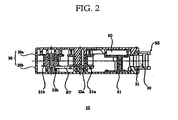
- Figure 2 is a sectional view of Figure 1 along the line 2-2.
- Figure 3 is a right side view of Figure 1 , and
- Figure 4 is an opposite side view of Figure 1 .
- Figure 5 illustrates the embodiment being used for spotting transfer
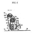
- Figures 6 and 7 illustrate the same being used for continuous transfer
- Figures 5-7 show a casing main body of a coating film transfer tool 10 without the cover 20b.
- the coating film transfer tool 10 of the present invention comprises a casing main body 20 composed of a case 20a and the cover 20b, a supply reel 21a which supplies a transfer tape T composed of a base tape and a coating film attached thereon, a transfer head 30 which is arranged at the end of the casing main body 20 and transfers the coating film onto a receiving surface as pressed against the surface, a take-up reel 21b which rolls up the base tape after transfer, a gear 40 which is provided coaxially on the supply reel 21a, a sliding member 50 having a pawl member 52 which engages with the gear 40 in only one direction and a cover member 55 which houses and protects the transfer head 30, and an elastic member 60 which holds the sliding member 50 to be movable within the casing main body 20.
- This embodiment employs a pressure-sensitive adhesive film as the coating film which is but one example.
- a roller is used as the transfer head 30.
- the supply reel 21a and the take-up reel 21b is rotatably supported by spindles 22a and 22b formed within the casing main body 20.
- the supply reel 21a and the take-up reel 21b rotate in conjunction with each other by means of an endless rubber belt BT (a belt-type cooperative drive mechanism), so that the transfer tape T wound on the supply reel 21a is unreeled.
- the coating film is transferred onto a receiving surface as the transfer head 30 is pressed down against the receiving surface.
- the used base tape which passed over the transfer head 30 contacts and attaches briefly with the coating film (adhesive film) of the transfer tape T wound on the supply reel 21a, and then is rolled up by the take-up reel 21b.
- the sliding body 50 comprises a sliding main body 51, the pawl member 52 which engages with the gear 40 only in the feed direction of the transfer tape T, an arm 53 which supports the pawl member 52, and the cover member 55 to protect the transfer head 30.
- the sliding body 50 is forward biased within the casing main body 20 by the elastic member 60 such as a coil spring, and held movable in a longitudinal direction of the casing main body 20.
- a groove 57 of the cover member 55 is for guiding a shaft 31 of the transfer head when the sliding member 50 is moved back and forth.
- the sliding main body 51, the pawl member 52, and the arm 53 are formed integrally and are illustrated as one component. However, they need not be one component and can be formed separately, with the only condition that the pawl member 52 works in conjunction with the sliding body 50.
- the cover member 55 is made openable and closable on the sliding main body 51, supported by a joint 54. And as described hereafter, opening and closing of the cover member 55 enable switchover between spotting transfer and continuous transfer.
- the transfer tool is for spotting transfer.
- the blacked part of the coating film 33 represents a portion to be transferred per pressing.
- the sliding body 50 When the transfer tool is released from pressing, the sliding body 50 is moved forward due to elastic force of the elastic member 60 to house the transfer head 30 therein.
- the pawl member 52 which moves with the sliding body 50 moves in an inverse direction to and hence engages with the gear 40. Consequently, the supply reel 21a rotates by predefined degrees as the pawl member 52 is moved forward, thereby supplying a predefined length of an unused transfer tape T.
- the coating film transfer tool 10 is used with the cover member 55 open, as is shown in an imaginary line in Figure 1 and as illustrated in Figure 6 .
- the transfer head 30 when the cover member 55 is open, the transfer head 30 is being placed out of the casing main body 20. Accordingly, the coating film can be smoothly and continuously transferred by using the transfer tool in the usual manner; by pressing the transfer head 30 against and moving it parallel to the receiving surface 71. Since the sliding body 50 is not moved back and forth when the cover member 55 is open, the pawl member 42 does not engage with the gear 40.
- the casing main body 20 can be provided with a stopper 23 for locking the cover member 55 in an open position.
- the present embodiment can also be used for continuous transfer with the cover member 55 in a closed position. More specifically, as the cover member 55 is pressed substantially orthogonally against the receiving surface 71, the sliding body 50 is pushed upward against elastic force of the elastic member 60, pushing out the transfer head 30 from the opening 56 of the cover member 55. Then the transfer head 30, pressed against the receiving surface 71, can be moved parallel to the receiving surface 71 to transfer the coating film continuously. As in the case of spotting transfer, the pawl member 52 which moves with the sliding body 50 is in a forward direction, and hence not in engagement, with the gear 40. Therefore, the transfer tape T is unreeled as the transfer head 30 moves on the receiving surface, transferring the coating film continuously onto the receiving surface 71. When the transfer tool is released from pressing, the pawl member 52, in engagement with the gear 40, rotates the supply reel 21a by predefined degrees as it is moved forward, thereby supplying a predefined length of the unused transfer tape T.
- the embodiment presents but one example of the forms of the casing main body 20, the sliding body 50, and the stopper 23, and of the arrangements of the supply reel 21a and take-up reel 21b, and therefore various modifications are possible.
- gear 40 is provided coaxially on the supply reel 21a in this embodiment, it can be arranged coaxially on the take-up reel 21b to achieve the same effect.
- a pressure-sensitive adhesive film was employed as a coating film in the embodiment, it can be a film for correction or a colored film for decoration.
- the coating film transfer tool of the present invention can be used to unfailingly transfer the coating film on a spot with the cover member of the sliding body in a closed position.
- the coating film transfer tool can be used in a usual manner to transfer the coating film over a wide range on the receiving surface.
- the present invention enabled switchover between spotting transfer by pressing and continuous transfer by pressing and parallel shifting with a simple operation of opening and closing the cover member of the sliding body, which remarkably improved handleability of the coating film transfer tool.
Landscapes
- Adhesive Tape Dispensing Devices (AREA)
Claims (2)
- Ein Beschichtungsfolientransferwerkzeug (10), das Folgendes enthält:eine Zufuhrrolle (21a) zum Zuführen eines Transferbands (T), das aus einem Trägerband und einer darauf angebrachten Beschichtungsfolie besteht,einen Transferkopf (30) zum Transfer besagter Beschichtungsfolie auf eine Empfängeroberfläche,eine Aufnahmerolle (21 b), welche nach erfolgtem Transfer das verbrauchte Trägerband aufnimmt,einen gemeinsamen Antriebsmechanismus, der so ausgelegt ist, dass er bewirkt, dass besagte Rollen sich gemeinsam drehen, und alles befindet sich in einem Gehäusehauptteil (20):ein koaxial auf besagter Zufuhrrolle (21 a) oder Aufnahmerolle (21b) angebrachtes Zahnrad (40);ein Schiebeteil (50), der ein Klinkenglied (52) enthält, welches in besagtes Zahnrad (40) in nur einer einzigen Richtung einrastet,ein Deckelglied (55), das besagten Transferkopf (30) enthält und mit einer Öffnung (56) versehen ist, welches besagte Deckelglied (55) mittels eines elastischen Glieds (60) in besagtem Gehäusehauptteil (20) beweglich gehalten wird und welches besagte Deckelglied am Schiebeteil (50) befestigt ist;dadurch gekennzeichnet, dass besagtes Deckelglied (55) an besagtem Schiebeteil (50) auf eine zu öffnende und zu schließende Weise befestigt ist;wobei, wenn sich besagtes Deckelglied in geschlossener Stellung befindet, das Hineindrücken des besagten Deckelglieds (55) in das Werkzeug (10) dafür sorgt, dass besagtes Schiebeteil (50) zurückgezogen wird und dass der Transferkopf (30) durch besagte Öffnung (56) des Deckelglieds (55) hervorgeschoben wird, ohne dass das Klinkenglied (52) in das Zahnrad (40) einrastet, und dass durch die Freigabe des besagten Deckelgliedes besagtes Schiebeteil (50) eine Vorwärtsbewegung des besagten Klinkenglieds (52) bewirkt, welches in besagtes Zahnrad (40) einrastet, um besagte Zufuhrrolle (21 a) oder besagte Aufhahmerolle (21b) des besagten Transferbandes (T) vorwärts zu bewegen, und dadurch eine Länge unbenutzten Transferbandes zuführt, wobei besagtes elastisches Glied durch die Freigabe des besagten Deckelgliedes in der Lage ist, das Schiebeteil elastisch in eine Richtung zu drücken, wodurch besagtes Klinkenglied ein Drehen des Zahnrads und Hervorstehen des besagten Transferkopfs aus besagter Öffnung bewirkt; undwenn sich besagtes Deckelglied in geöffneter Stellung befindet, steht besagter Transferkopf (30) aus dem Werkzeug hervor, wobei der Transferkopf so ausgelegt ist, dass ein ständiger Transfer der Beschichtungsfolie erfolgt, wenn besagter Transferkopf über eine Oberfläche bewegt wird, undwobei der Transferkopf eine Rolle ist.
- Ein Beschichtungsfolientransferwerkzeug gemäß dem Anspruch in Patentanspruch 1, wobei besagtes Gehäusehauptteil mit einer Sperre versehen ist, die besagtes Deckelglied in geöffneter Stellung verriegelt.
Applications Claiming Priority (2)
| Application Number | Priority Date | Filing Date | Title |
|---|---|---|---|
| JP2006028117A JP4769964B2 (ja) | 2006-02-06 | 2006-02-06 | 塗膜転写具 |
| PCT/JP2007/051537 WO2007091454A1 (ja) | 2006-02-06 | 2007-01-24 | 塗膜転写具 |
Publications (3)
| Publication Number | Publication Date |
|---|---|
| EP1982844A1 EP1982844A1 (de) | 2008-10-22 |
| EP1982844A4 EP1982844A4 (de) | 2011-04-13 |
| EP1982844B1 true EP1982844B1 (de) | 2013-09-11 |
Family
ID=38345057
Family Applications (1)
| Application Number | Title | Priority Date | Filing Date |
|---|---|---|---|
| EP07707755.0A Active EP1982844B1 (de) | 2006-02-06 | 2007-01-24 | Beschichtungstransferwerkzeug |
Country Status (4)
| Country | Link |
|---|---|
| US (1) | US7784517B2 (de) |
| EP (1) | EP1982844B1 (de) |
| JP (1) | JP4769964B2 (de) |
| WO (1) | WO2007091454A1 (de) |
Families Citing this family (22)
| Publication number | Priority date | Publication date | Assignee | Title |
|---|---|---|---|---|
| JP4737642B2 (ja) * | 2007-05-09 | 2011-08-03 | ニチバン株式会社 | 粘着転写具 |
| JP4972787B2 (ja) * | 2007-07-27 | 2012-07-11 | コクヨ株式会社 | 転写具 |
| JP5116098B2 (ja) * | 2008-03-31 | 2013-01-09 | ニチバン株式会社 | 粘着転写具 |
| JP5011558B2 (ja) * | 2008-10-02 | 2012-08-29 | コクヨ株式会社 | 転写具 |
| JP5857289B2 (ja) * | 2010-07-14 | 2016-02-10 | デュプロ精工株式会社 | 封緘装置 |
| US8397784B2 (en) | 2010-08-31 | 2013-03-19 | Sanford, L.P. | Correction tape dispenser with variable clutch mechanism |
| JP5618362B2 (ja) * | 2010-10-13 | 2014-11-05 | ユニオンケミカー株式会社 | 塗膜転写具 |
| TWD144793S (zh) * | 2010-11-10 | 2012-01-01 | 國譽股份有限公司 | 事務用塗膜轉印器 |
| US8746313B2 (en) | 2010-12-29 | 2014-06-10 | Sanford, L.P. | Correction tape re-tensioning mechanism and correction tape dispenser comprising same |
| US8578999B2 (en) | 2010-12-29 | 2013-11-12 | Sanford, L.P. | Variable clutch mechanism and correction tape dispenser with variable clutch mechanism |
| US8746316B2 (en) | 2011-12-30 | 2014-06-10 | Sanford, L.P. | Variable clutch mechanism and correction tape dispenser with variable clutch mechanism |
| JP6524627B2 (ja) * | 2014-09-26 | 2019-06-05 | コクヨ株式会社 | 転写具 |
| JP6247199B2 (ja) | 2014-12-09 | 2017-12-13 | 株式会社トンボ鉛筆 | 塗膜転写具 |
| JP6321537B2 (ja) | 2014-12-26 | 2018-05-09 | 株式会社トンボ鉛筆 | 塗膜転写具 |
| JP6576681B2 (ja) * | 2015-05-07 | 2019-09-18 | 日東電工株式会社 | 巻き芯保護用粘着シート、保護済巻き芯、およびフィルムの巻き取り巻き替え方法 |
| CN109414951B (zh) * | 2016-06-24 | 2020-08-07 | 株式会社蜻蜓铅笔 | 横拉型涂膜转印具 |
| JP7095856B2 (ja) | 2017-07-04 | 2022-07-05 | 株式会社トンボ鉛筆 | 塗膜転写具 |
| WO2019008687A1 (ja) | 2017-07-04 | 2019-01-10 | 株式会社トンボ鉛筆 | 塗膜転写具 |
| JP7031269B2 (ja) * | 2017-12-08 | 2022-03-08 | コクヨ株式会社 | 転写具 |
| JP7219943B2 (ja) | 2018-03-13 | 2023-02-09 | 株式会社トンボ鉛筆 | 感圧転写修正テープ |
| JP7248424B2 (ja) * | 2018-12-28 | 2023-03-29 | 日東電工株式会社 | 粘着体送出装置及び粘着体送出方法 |
| JP7122985B2 (ja) * | 2019-02-26 | 2022-08-22 | コクヨ株式会社 | 転写具 |
Family Cites Families (10)
| Publication number | Priority date | Publication date | Assignee | Title |
|---|---|---|---|---|
| US3889310A (en) * | 1973-11-23 | 1975-06-17 | Victor Barouh | Typewriter correction device employing an adhesive ribbon |
| DE3911402A1 (de) * | 1989-04-07 | 1990-10-11 | Wischerath Josef Gmbh Co Kg | Vorrichtung zum aufbringen eines adhaesiven materials |
| US5316613A (en) * | 1991-09-06 | 1994-05-31 | Minnesota Mining And Manufacturing Company | Definite length transfer adhesive dispenser |
| JPH0655895A (ja) * | 1992-08-11 | 1994-03-01 | Tombow Pencil Co Ltd | 字消し具 |
| JP3296265B2 (ja) * | 1997-09-12 | 2002-06-24 | 株式会社シード | 塗膜転写具のクラッチ機構および塗膜転写具 |
| JP3998221B2 (ja) * | 1998-02-16 | 2007-10-24 | 株式会社パイロットコーポレーション | 転写具 |
| DE19905878A1 (de) * | 1999-02-11 | 2000-08-17 | Michael Grobbel | Vorrichtung zum flächenhaften Auftragen eines Films von einem Trägerband auf ein Objekt oder Substrat |
| DE19905900A1 (de) * | 1999-02-11 | 2000-08-17 | Michael Groppel | Vorrichtung zum flächenhaften Auftragen eines Films von einem Trägerband auf ein Objekt oder Substrat |
| JP2002264588A (ja) * | 2001-03-14 | 2002-09-18 | Tombow Pencil Co Ltd | 塗膜転写具 |
| US7163040B2 (en) * | 2004-01-13 | 2007-01-16 | Sanford L.P. | Correction tape applicator tip with cylindrical projection |
-
2006
- 2006-02-06 JP JP2006028117A patent/JP4769964B2/ja not_active Expired - Fee Related
-
2007
- 2007-01-24 WO PCT/JP2007/051537 patent/WO2007091454A1/ja not_active Ceased
- 2007-01-24 EP EP07707755.0A patent/EP1982844B1/de active Active
- 2007-01-24 US US12/223,561 patent/US7784517B2/en not_active Expired - Fee Related
Also Published As
| Publication number | Publication date |
|---|---|
| EP1982844A1 (de) | 2008-10-22 |
| JP2007203691A (ja) | 2007-08-16 |
| JP4769964B2 (ja) | 2011-09-07 |
| EP1982844A4 (de) | 2011-04-13 |
| US20090050275A1 (en) | 2009-02-26 |
| US7784517B2 (en) | 2010-08-31 |
| WO2007091454A1 (ja) | 2007-08-16 |
Similar Documents
| Publication | Publication Date | Title |
|---|---|---|
| EP1982844B1 (de) | Beschichtungstransferwerkzeug | |
| JP3296265B2 (ja) | 塗膜転写具のクラッチ機構および塗膜転写具 | |
| US7766066B2 (en) | Coating film transfer tool | |
| JP4617430B2 (ja) | 塗膜転写具 | |
| CN109203794B (zh) | 涂膜转印具 | |
| US20080277517A1 (en) | Coating film transfer tool | |
| CA2091996C (en) | Device for transferring film | |
| US20060090857A1 (en) | Coating film transfer tool | |
| KR100313654B1 (ko) | 도포구 | |
| JPH11348493A (ja) | 塗膜転写具用テープカートリッジおよび塗膜転写具 | |
| WO2010038604A1 (ja) | 転写具 | |
| JPH092724A (ja) | 塗布膜転写具及び塗布膜転写具における転写テープ詰替方法 | |
| TWI725245B (zh) | 塗膜轉印具 | |
| JP2008279719A (ja) | 塗膜転写具 | |
| EP3312020B1 (de) | Übertragungswerkzeug für beschichtungsfilm | |
| JP2020062849A (ja) | 塗膜転写具 | |
| JP7302249B2 (ja) | 塗膜転写具 | |
| JP3712723B2 (ja) | 転写テープ式修正具 | |
| JP4461675B2 (ja) | 転写具の転写ヘッド部構造および転写具 | |
| JP4338172B2 (ja) | 転写テープ具 | |
| JP2012106466A (ja) | スライディングスタンプ塗膜転写具 | |
| JP2004306619A5 (de) | ||
| JP7160478B2 (ja) | 塗膜転写具 | |
| JP7330496B2 (ja) | 塗膜転写具 | |
| JP2008093951A (ja) | 塗膜転写具 |
Legal Events
| Date | Code | Title | Description |
|---|---|---|---|
| PUAI | Public reference made under article 153(3) epc to a published international application that has entered the european phase |
Free format text: ORIGINAL CODE: 0009012 |
|
| 17P | Request for examination filed |
Effective date: 20080808 |
|
| AK | Designated contracting states |
Kind code of ref document: A1 Designated state(s): DE FR GB |
|
| DAX | Request for extension of the european patent (deleted) | ||
| RBV | Designated contracting states (corrected) |
Designated state(s): DE FR GB |
|
| A4 | Supplementary search report drawn up and despatched |
Effective date: 20110316 |
|
| GRAP | Despatch of communication of intention to grant a patent |
Free format text: ORIGINAL CODE: EPIDOSNIGR1 |
|
| RIC1 | Information provided on ipc code assigned before grant |
Ipc: B43L 19/00 20060101AFI20130321BHEP Ipc: B65H 37/00 20060101ALI20130321BHEP |
|
| INTG | Intention to grant announced |
Effective date: 20130417 |
|
| GRAJ | Information related to disapproval of communication of intention to grant by the applicant or resumption of examination proceedings by the epo deleted |
Free format text: ORIGINAL CODE: EPIDOSDIGR1 |
|
| GRAP | Despatch of communication of intention to grant a patent |
Free format text: ORIGINAL CODE: EPIDOSNIGR1 |
|
| INTG | Intention to grant announced |
Effective date: 20130702 |
|
| GRAS | Grant fee paid |
Free format text: ORIGINAL CODE: EPIDOSNIGR3 |
|
| GRAA | (expected) grant |
Free format text: ORIGINAL CODE: 0009210 |
|
| AK | Designated contracting states |
Kind code of ref document: B1 Designated state(s): DE FR GB |
|
| REG | Reference to a national code |
Ref country code: GB Ref legal event code: FG4D |
|
| REG | Reference to a national code |
Ref country code: DE Ref legal event code: R096 Ref document number: 602007032785 Country of ref document: DE Effective date: 20131107 |
|
| REG | Reference to a national code |
Ref country code: DE Ref legal event code: R097 Ref document number: 602007032785 Country of ref document: DE |
|
| PLBE | No opposition filed within time limit |
Free format text: ORIGINAL CODE: 0009261 |
|
| STAA | Information on the status of an ep patent application or granted ep patent |
Free format text: STATUS: NO OPPOSITION FILED WITHIN TIME LIMIT |
|
| 26N | No opposition filed |
Effective date: 20140612 |
|
| REG | Reference to a national code |
Ref country code: DE Ref legal event code: R097 Ref document number: 602007032785 Country of ref document: DE Effective date: 20140612 |
|
| REG | Reference to a national code |
Ref country code: FR Ref legal event code: PLFP Year of fee payment: 10 |
|
| REG | Reference to a national code |
Ref country code: FR Ref legal event code: PLFP Year of fee payment: 11 |
|
| REG | Reference to a national code |
Ref country code: FR Ref legal event code: PLFP Year of fee payment: 12 |
|
| PGFP | Annual fee paid to national office [announced via postgrant information from national office to epo] |
Ref country code: DE Payment date: 20250121 Year of fee payment: 19 |
|
| PGFP | Annual fee paid to national office [announced via postgrant information from national office to epo] |
Ref country code: FR Payment date: 20250127 Year of fee payment: 19 |
|
| PGFP | Annual fee paid to national office [announced via postgrant information from national office to epo] |
Ref country code: GB Payment date: 20250128 Year of fee payment: 19 |