EP1980454B1 - Airbagabdeckung mit einem Emblem - Google Patents
Airbagabdeckung mit einem Emblem Download PDFInfo
- Publication number
- EP1980454B1 EP1980454B1 EP07381031A EP07381031A EP1980454B1 EP 1980454 B1 EP1980454 B1 EP 1980454B1 EP 07381031 A EP07381031 A EP 07381031A EP 07381031 A EP07381031 A EP 07381031A EP 1980454 B1 EP1980454 B1 EP 1980454B1
- Authority
- EP
- European Patent Office
- Prior art keywords
- snap
- emblem
- cover
- parts
- fitting plate
- Prior art date
- Legal status (The legal status is an assumption and is not a legal conclusion. Google has not performed a legal analysis and makes no representation as to the accuracy of the status listed.)
- Active
Links
Images
Classifications
-
- B—PERFORMING OPERATIONS; TRANSPORTING
- B60—VEHICLES IN GENERAL
- B60R—VEHICLES, VEHICLE FITTINGS, OR VEHICLE PARTS, NOT OTHERWISE PROVIDED FOR
- B60R21/00—Arrangements or fittings on vehicles for protecting or preventing injuries to occupants or pedestrians in case of accidents or other traffic risks
- B60R21/02—Occupant safety arrangements or fittings, e.g. crash pads
- B60R21/16—Inflatable occupant restraints or confinements designed to inflate upon impact or impending impact, e.g. air bags
- B60R21/20—Arrangements for storing inflatable members in their non-use or deflated condition; Arrangement or mounting of air bag modules or components
- B60R21/215—Arrangements for storing inflatable members in their non-use or deflated condition; Arrangement or mounting of air bag modules or components characterised by the covers for the inflatable member
- B60R21/2165—Arrangements for storing inflatable members in their non-use or deflated condition; Arrangement or mounting of air bag modules or components characterised by the covers for the inflatable member characterised by a tear line for defining a deployment opening
-
- B—PERFORMING OPERATIONS; TRANSPORTING
- B60—VEHICLES IN GENERAL
- B60R—VEHICLES, VEHICLE FITTINGS, OR VEHICLE PARTS, NOT OTHERWISE PROVIDED FOR
- B60R21/00—Arrangements or fittings on vehicles for protecting or preventing injuries to occupants or pedestrians in case of accidents or other traffic risks
- B60R21/02—Occupant safety arrangements or fittings, e.g. crash pads
- B60R21/16—Inflatable occupant restraints or confinements designed to inflate upon impact or impending impact, e.g. air bags
- B60R21/20—Arrangements for storing inflatable members in their non-use or deflated condition; Arrangement or mounting of air bag modules or components
- B60R21/215—Arrangements for storing inflatable members in their non-use or deflated condition; Arrangement or mounting of air bag modules or components characterised by the covers for the inflatable member
- B60R2021/21543—Arrangements for storing inflatable members in their non-use or deflated condition; Arrangement or mounting of air bag modules or components characterised by the covers for the inflatable member with emblems
Definitions
- the present invention relates to an airbag cover for an automotive vehicle with an emblem fixed thereto, such as a logotype of the vehicle manufacturer, and more particularly with an emblem snap-fit to the cover.
- the airbag cover is made of a soft plastic
- the emblem is also made of a soft plastic and the perforation line of the cover traverses the emblem.
- the airbag cover is made of a soft plastic
- the emblem is made of a hard plastic usually with special coating providing it with a metallic appearance
- the perforation line is arranged surrounding the emblem so as to not traverse it.
- the fixing of the emblem to the airbag cover can be done in several manners.
- Another one of these fixings is fixing the emblem to the cover using snap-fitting means.
- This type of fixing has the drawback that the snap-fitting plate confers excessive rigidity to the emblem-cover-snap-fitting plate assembly during the opening of the cover at the time of airbag deployment, making it difficult for the emblem to follow the bending of the cover, possibly causing it to break with the subsequent risk for the vehicle occupant.
- An object of the present invention is to allow the incorporation of emblems formed by two or more independent parts on the cover of an airbag module by simple fixing means without risks that parts of the emblem can be released, causing injuries to the vehicle occupant when the airbag cover breaks along the pre-established perforation lines so as to allow airbag deployment.
- an airbag cover for automotive vehicles with means for predetermining its breaking during the deployment of the airbag cushion, which incorporates an emblem formed by at least two independent parts which is fixed to the cover by means of the aid of one or more rods arranged on its inner face with a snap-fitting plate arranged inside the cover and comprising at least two areas, each of which includes snap-fitting means cooperating with said rods and an intermediate area between them which is configured such that it can work as a bending area of the snap-fitting plate during the deployment of the airbag cushion, allowing relative movement between the parts of the emblem.
- said intermediate area includes a part having less thickness than the rest, facilitating its deformation to be adapted to the movement of the cover during the deployment of the airbag cushion.
- the snap-fitting means of the snap-fitting plate consist of elastic bodies with central holes cooperating with rods with enlarged end parts allowing their passage through said holes but preventing movement in the opposite direction.
- the emblem has two parts each of which has a rod, and the snap-fitting part has two elastic bodies.
- the emblem has two parts each of which has two rods, and the snap-fitting part has four elastic bodies arranged such that their central points occupy the corners of a hypothetical rectangle.
- the emblem has two parts each of which has two rods, and the snap-fitting parts has four elastic bodies arranged such that their central points occupy the corners of a hypothetical rectangle.
- the emblem has three parts each of which has a rod, and the snap-fitting part has three elastic bodies.
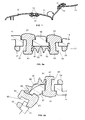
- Figure 1 shows an airbag cover 11 according to the present invention incorporating an emblem 13 formed by two independent parts and fixed to the cover 11 by means of a snap-fitting plate 17.
- the cover 11 includes a perforated line 9 by means of which it will break during deployment of the airbag. Once this occurs and as is shown in the right part of Figure 1 , the emblem 13 allows the part of the cover 11 separating during the exit of the airbag cushion to acquire a certain degree of bending, which is beneficial for preventing the release of parts of the cover that may injure the vehicle occupant.
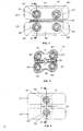
- Figures 2 and 3 along with Figures 5a and 5b show a first embodiment of the invention in which the emblem 13 is formed by two independent parts 21, 23, schematically shown in Figure 2 , with rounded rectangular shaped heads and a snap-fitting plate 17 shown in Figure 2 with a rectangular shape, and with a shape similar to that of a four-leaf clover in Figure 3 .
- Part 21 includes rods 41, 41' for its fixing to the snap-fitting plate 17 by means of snap-fitting.
- part 23 includes rods 43, 43' for its fixing by snap-fitting to the snap-fitting plate 17.
- the snap-fitting plate 17 has two elastic bodies 51, 51' with central holes 61, 61' to receive the rods 41, 41' of part 21 and two elastic bodies 53, 53' with two central holes 63, 63' to receive the rods 43, 43' of part 23.
- the rods 41, 41', 43, , 43' end with an enlarged body and the elastic bodies 51, 51', 53, 53' with the central holes 61, 61', 63, 63' of the plate 17 allow the passage through these holes of the enlarged bodies of the end parts of the rods 41, 41', 43, 43', but they prevent opposite movement.
- the invention comprises these specific snap-fitting means and any other equivalent means.
- the snap-fitting plate 17 is structured in a first area 31 in which the elastic bodies 51, 51' with the holes 61, 61' receiving the rods 41, 41' of the first part 21 of the emblem 13 are located, a second area 35 in which the elastic bodies 53, 53' with the holes 63, 63' receiving the rods 43, 43' of the second part 23 of the emblem 13 are located, and an intermediate area 33 between both, the central part 39 of which has less thickness than the rest.
- Figures 5a and 5b also show in greater detail that the cover 11 includes an offset area for the incorporation of the parts 21 and 23 on both sides of its central part 12 and the snap-fitting between the enlarged end body of the rods 41 and 43 and the elastic bodies 51, 53 which are arranged, respectively, around the holes 61 and 63 of the snap-fitting plate 17.
- the rods 41, 41', 43, 43' of the parts 21, 23 of the emblem 13 and the central points of the elastic bodies 51, 51', 53, 53' of the snap-fitting plate are arranged in the hypothetical corners of a rectangle, in the attempt that the dimensions are as small as possible, being compatible with the shape of the emblem 13.
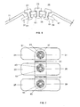
- Figure 4 shows a second embodiment of the invention similar to the first embodiment, except that in the two parts 21, 23 of the emblem only one rod 41, 43 instead of two rods is incorporated and instead of having two elastic bodies in each area 31, 35 the snap-fitting plate only has one elastic body 51, 53 to receive said rods 41, 43.
- Figures 6 and 7 show a third embodiment of the invention in which the emblem is formed by three independent parts 21, 23, 25, each of them including a rod 41, 43, 45 and a snap-fitting plate 17 which is structured in a first area 31 in which an elastic body 51 with a hole 61 for receiving the rod 41 is located, a second area 35 in which an elastic body 53 with a hole 63 for receiving the rod 43 is located and a third area in which an elastic body 55 with a hole 65 for receiving the rod 45 is located.
- Areas 31, 35, 39 are separated by intermediate areas 33, 37 with a central part having less thickness working, like in the other embodiments of the invention, as a bending area of the snap-fitting plate 17 during deployment of the airbag cushion, allowing relative movement between the three parts 21, 23, 25 of the emblem.
Landscapes
- Engineering & Computer Science (AREA)
- Mechanical Engineering (AREA)
- Air Bags (AREA)
Claims (8)
- Eine Luftsackabdeckung (11) für Kraftfahrzeuge mit Mitteln zum vorherbestimmten Aufbrechen der Luftsackabdeckung während der Entfaltung des Luftsackes, mit einem Emblem (13), welches an der Abdeckung (11) durch, auf seiner Innenseite angebrachte, ein oder mehrere hilfsweise angeordnete Streben fixiert ist, mittels einer Schnappverbindungsplatte, die innerhalb der Abdeckung (11) angebracht ist, wobei:a) das Emblem (13) wenigstens von zwei Teilen (21, 23) gebildet ist;c) die Schnappverbindungs-Platte (17) wenigstens zwei Bereiche (31, 35) aufweist, die je Schnappverbindungsmittel aufweisen, welche mit den Streben der wenigstens zwei Teile (21, 23) in Eingriff stehen, dadurch gekennzeichnet, dass die zwei Teile (21, 23) eigenständig sind und ein zwischen ihnen liegender Übergangsbereich (33) derart ausgestaltet ist, dass er, während der Entfaltung des Luftsackkissens, als Biegebereich der Schnappverbindungs-Platte (17) dienen kann, indem er eine Relativbewegung zwischen den Teilen (21, 23) des Emblems (13) ermöglicht.
- Eine Luftsackabdeckung (11) für Kraftfahrzeuge nach Anspruch 1, dadurch gekennzeichnet, dass der Übergangsbereich (33) einen Abschnitt (39) mit geringerer Dicke aufweist.
- Eine Luftsackabdeckung (11) für Kraftfahrzeuge nach Anspruch 1 oder 2, dadurch gekennzeichnet, dass die Schnappverbindungs-Mittel, die mit den Streben in Eingriff stehen, aus elastischen Gebilden mit mittigen Löchern bestehen.
- Eine Luftsackabdeckung (11) für Kraftfahrzeuge nach Anspruch 3, dadurch gekennzeichnet, dass das Emblem (13) von zwei eigenständigen Teilen (21, 23) gebildet wird, wobei jedes Teil eine Strebe (41, 43) aufweist und, dass die Schnappverbindungs-Platte (17) zwei elastische Gebilde (51; 53) mit mittigen Löchern (61; 63) aufweist.
- Eine Luftsackabdeekung (11) für Kraftfahrzeuge nach Anspruch 3, dadurch gekennzeichnet, dass das Emblem (13) von zwei eigenständigen Teilen (21, 23) gebildet wird, wobei jedes Teil zwei Streben (41, 41 43, 43') aufweist und, dass die Schnappverbindungs-Platte (17) vier elastische Gebilde (51, 51'; 53, 53') mit mittigen Löchern (61, 61'; 63, 63') aufweist.
- Eine Luftsackabdeckung (11) für Kraftfahrzeuge nach Anspruch 5, dadurch gekennzeichnet, dass die Streben (41, 41'; 43, 43') auf der Abdeckung (11) in den theoretischen Ecken eines Viereckes angeordnet sind.
- Eine Luftsackabdeckung (11) für Kraftfahrzeuge nach Anspruch 5, dadurch gekennzeichnet, dass die Schnappverbindungs-Platte (17) die Form eines vierblättrigen Kleeblattes aufweist, wobei die vier elastischen Gebilde (51, 51'; 53, 53') jeweils in einem der vier Kleeblattabschttitte angeordnet sind.
- Eine Luftsackabdeckung (11) für Kraftfahrzeuge nach einem der Ansprüche 1 bis 3, dadurch gekennzeichnet, dass das Emblem (13) von drei eigenständigen Teilen (21, 23, 25) gebildet wird, wobei jedes Teil eine Strebe (41, 43, 45) aufweist und, dass die Schnappverbindungs-Platte (17) drei Bereiche (31, 35, 39) mit je einem elastischen Gebilde (51, 53, 55) und zwei dazwischen liegenden Übergangsbereichen (33, 37) aufweist.
Priority Applications (4)
| Application Number | Priority Date | Filing Date | Title |
|---|---|---|---|
| DE602007004192T DE602007004192D1 (de) | 2007-04-10 | 2007-04-10 | Airbagabdeckung mit einem Emblem |
| AT07381031T ATE454294T1 (de) | 2007-04-10 | 2007-04-10 | Airbagabdeckung mit einem emblem |
| EP07381031A EP1980454B1 (de) | 2007-04-10 | 2007-04-10 | Airbagabdeckung mit einem Emblem |
| US12/082,075 US7775550B2 (en) | 2007-04-10 | 2008-04-08 | Airbag cover with an emblem |
Applications Claiming Priority (1)
| Application Number | Priority Date | Filing Date | Title |
|---|---|---|---|
| EP07381031A EP1980454B1 (de) | 2007-04-10 | 2007-04-10 | Airbagabdeckung mit einem Emblem |
Publications (2)
| Publication Number | Publication Date |
|---|---|
| EP1980454A1 EP1980454A1 (de) | 2008-10-15 |
| EP1980454B1 true EP1980454B1 (de) | 2010-01-06 |
Family
ID=38326999
Family Applications (1)
| Application Number | Title | Priority Date | Filing Date |
|---|---|---|---|
| EP07381031A Active EP1980454B1 (de) | 2007-04-10 | 2007-04-10 | Airbagabdeckung mit einem Emblem |
Country Status (4)
| Country | Link |
|---|---|
| US (1) | US7775550B2 (de) |
| EP (1) | EP1980454B1 (de) |
| AT (1) | ATE454294T1 (de) |
| DE (1) | DE602007004192D1 (de) |
Families Citing this family (12)
| Publication number | Priority date | Publication date | Assignee | Title |
|---|---|---|---|---|
| US8459713B2 (en) * | 2010-08-09 | 2013-06-11 | Autoliv Asp, Inc. | Assembly for attaching an emblem onto an airbag storage compartment cover |
| JP5494540B2 (ja) * | 2011-03-25 | 2014-05-14 | 豊田合成株式会社 | エアバッグカバー |
| JP5921372B2 (ja) * | 2012-03-27 | 2016-05-24 | タカタ株式会社 | エアバッグ装置、締結構造及び締結部材 |
| JP5950444B2 (ja) * | 2012-04-27 | 2016-07-13 | 日本プラスト株式会社 | エアバッグ装置のカバー体 |
| DE202014001873U1 (de) * | 2014-03-04 | 2015-06-08 | Dalphi Metal Espana S.A. | Baugruppe zur ästhetischen Gestaltung einer Gassackabdeckung, Gassackabdeckung, Gassackmodul und Fahrzeuglenkrad mit jeweils einer derartigen Baugruppe |
| DE202014002912U1 (de) * | 2014-04-04 | 2015-07-07 | Dalphi Metal Espana, S.A. | Emblembaugruppe zur Verbindung mit einer Gassackabdeckung, Abdeckung für ein Gassackmodul, Gassackmodul und Lenkrad mit einer derartigen Emblembaugruppe |
| DE202014008757U1 (de) * | 2014-11-05 | 2016-02-08 | Dalphi Metal Espana, S.A. | Emblembaugruppe zur Verbindung mit einer Gassackabdeckung, Gassackabdeckung, Gassackmodul und Fahrzeuglenkrad mit einer derartigen Emblembaugruppe |
| DE202018103540U1 (de) * | 2018-06-22 | 2019-10-07 | Dalphi Metal Espana, S.A. | Abdeckkappe eines Gassackmoduls, Gassackmodul sowie Werkzeug zum Herstellen einer solchen Abdeckkappe |
| DE202018104587U1 (de) * | 2018-08-09 | 2019-11-19 | Dalphi Metal Espana, S.A. | Abdeckkappe für ein Gassackmodul sowie Gassackmodul mit einer solchen Abdeckkappe |
| DE202018104588U1 (de) * | 2018-08-09 | 2019-11-14 | Dalphi Metal Espana, S.A. | Abdeckkappe für ein Gassackmodul sowie Gassackmodul mit einer solchen Abdeckkappe |
| DE102018218403B4 (de) * | 2018-10-26 | 2020-08-06 | Joyson Safety Systems Germany Gmbh | Anordnung zum Abdecken eines Gassacks eines Fahrzeuginsassen-Rückhaltesystems |
| JP7179592B2 (ja) * | 2018-11-26 | 2022-11-29 | 日本プラスト株式会社 | エアバッグ装置のカバー体 |
Family Cites Families (16)
| Publication number | Priority date | Publication date | Assignee | Title |
|---|---|---|---|---|
| US5851022A (en) * | 1995-03-31 | 1998-12-22 | Toyoda Gosei Co., Ltd. | Air bag pad with decorative device |
| US5678851A (en) * | 1995-04-28 | 1997-10-21 | Nihon Plast Co., Ltd. | Airbag module cover |
| DE29507890U1 (de) * | 1995-05-12 | 1995-07-27 | Trw Repa Gmbh, 73553 Alfdorf | Abdeckung für ein Gassackrückhaltesystem in Fahrzeugen |
| JPH10119683A (ja) * | 1996-10-17 | 1998-05-12 | Nippon Plast Co Ltd | エアバッグ装置のカバー体 |
| DE29706136U1 (de) * | 1997-03-24 | 1997-06-12 | Petri Ag, 63743 Aschaffenburg | Auf einer Grundplatte befestigte Plakette |
| US6168187B1 (en) * | 1997-07-01 | 2001-01-02 | Toyoda Gosei Co., Ltd. | Cover for an air bag |
| US6047984A (en) * | 1998-04-06 | 2000-04-11 | Larry J. Winget | Air bag cover and method of making same |
| US6099027A (en) * | 1998-06-29 | 2000-08-08 | Trw Inc. | Decorative emblem for air bag module cover |
| DE19829755B4 (de) * | 1998-07-03 | 2004-07-22 | Daimlerchrysler Ag | Airbagvorrichtung für ein Kraftfahrzeug |
| JP2001225703A (ja) * | 1999-12-07 | 2001-08-21 | Tokai Rika Co Ltd | プレート体のパッドカバーへの取付構造 |
| JP3833428B2 (ja) * | 1999-12-14 | 2006-10-11 | 豊田合成株式会社 | 成形品に対する加飾品の取付構造 |
| JP4734702B2 (ja) * | 2000-02-29 | 2011-07-27 | タカタ株式会社 | エアバッグ装置のカバー体の製造方法及びカバー体本体 |
| DE10042527A1 (de) * | 2000-08-30 | 2002-03-28 | Audi Ag | Insassenschutzvorrichtung eines Fahrzeugs mit einem Airbagmodul |
| DE20114507U1 (de) * | 2001-09-03 | 2002-01-24 | Trw Automotive Safety Sys Gmbh | Gassackmodul |
| JP3900005B2 (ja) * | 2002-05-14 | 2007-04-04 | 豊田合成株式会社 | オーナメントを備えたエアバッグカバー |
| US7097199B2 (en) * | 2003-09-25 | 2006-08-29 | Autoliv Asp, Inc. | Airbag cover emblem attachment apparatus and method |
-
2007
- 2007-04-10 EP EP07381031A patent/EP1980454B1/de active Active
- 2007-04-10 DE DE602007004192T patent/DE602007004192D1/de active Active
- 2007-04-10 AT AT07381031T patent/ATE454294T1/de not_active IP Right Cessation
-
2008
- 2008-04-08 US US12/082,075 patent/US7775550B2/en active Active
Also Published As
| Publication number | Publication date |
|---|---|
| ATE454294T1 (de) | 2010-01-15 |
| EP1980454A1 (de) | 2008-10-15 |
| DE602007004192D1 (de) | 2010-02-25 |
| US7775550B2 (en) | 2010-08-17 |
| US20080252050A1 (en) | 2008-10-16 |
Similar Documents
| Publication | Publication Date | Title |
|---|---|---|
| EP1980454B1 (de) | Airbagabdeckung mit einem Emblem | |
| JP5133132B2 (ja) | エアバッグカバー及びエアバッグ装置 | |
| US6543838B1 (en) | Vehicle door provided with pelvis thrust means | |
| DE19908702A1 (de) | Beifahrersitz-Airbag | |
| EP3833580B1 (de) | Abdeckkappe für ein gassackmodul sowie gassackmodul mit einer solchen abdeckkappe | |
| JP2006088774A (ja) | 後席用サイドエアバッグ装置 | |
| CN107933449A (zh) | 车辆用绳夹 | |
| DE60113212T2 (de) | Airbagrückhalteelement | |
| JP2004268911A (ja) | 装飾要素 | |
| EP3833581B1 (de) | Abdeckkappe für ein gassackmodul sowie gassackmodul mit einer solchen abdeckkappe | |
| US7384061B2 (en) | Trim panel and a method of manufacture | |
| GB2070425A (en) | Arm-rest for a vehicle | |
| US10894518B2 (en) | Door trim | |
| DE102008005419B3 (de) | Gassackabdeckung | |
| CN107415787B (zh) | 具有动态碰撞能量管理系统的车辆座椅和头枕 | |
| JPH0885406A (ja) | 自動車用エアバッグドアの構造 | |
| EP1923275A2 (de) | Airbag-Modul für Kraftfahrzeuglenkräder | |
| EP3060433B1 (de) | Sitzanordnung | |
| JP5145976B2 (ja) | 車両用ドアトリム | |
| JP2601700Y2 (ja) | インストルメントパネル | |
| JP4541130B2 (ja) | インストルメントパネル | |
| CN210881630U (zh) | 一种车门内饰板防撞机构以及车门 | |
| JP7463763B2 (ja) | 車両用アームレスト | |
| JP3948915B2 (ja) | 車両の内装用パネル構造 | |
| CN209274723U (zh) | 一种汽车a柱的固定座及汽车 |
Legal Events
| Date | Code | Title | Description |
|---|---|---|---|
| PUAI | Public reference made under article 153(3) epc to a published international application that has entered the european phase |
Free format text: ORIGINAL CODE: 0009012 |
|
| AK | Designated contracting states |
Kind code of ref document: A1 Designated state(s): AT BE BG CH CY CZ DE DK EE ES FI FR GB GR HU IE IS IT LI LT LU LV MC MT NL PL PT RO SE SI SK TR |
|
| AX | Request for extension of the european patent |
Extension state: AL BA HR MK RS |
|
| 17P | Request for examination filed |
Effective date: 20090113 |
|
| R17P | Request for examination filed (corrected) |
Effective date: 20090109 |
|
| GRAP | Despatch of communication of intention to grant a patent |
Free format text: ORIGINAL CODE: EPIDOSNIGR1 |
|
| AKX | Designation fees paid |
Designated state(s): AT BE BG CH CY CZ DE DK EE ES FI FR GB GR HU IE IS IT LI LT LU LV MC MT NL PL PT RO SE SI SK TR |
|
| GRAS | Grant fee paid |
Free format text: ORIGINAL CODE: EPIDOSNIGR3 |
|
| GRAA | (expected) grant |
Free format text: ORIGINAL CODE: 0009210 |
|
| AK | Designated contracting states |
Kind code of ref document: B1 Designated state(s): AT BE BG CH CY CZ DE DK EE ES FI FR GB GR HU IE IS IT LI LT LU LV MC MT NL PL PT RO SE SI SK TR |
|
| REG | Reference to a national code |
Ref country code: GB Ref legal event code: FG4D |
|
| REG | Reference to a national code |
Ref country code: CH Ref legal event code: EP |
|
| REG | Reference to a national code |
Ref country code: IE Ref legal event code: FG4D |
|
| REF | Corresponds to: |
Ref document number: 602007004192 Country of ref document: DE Date of ref document: 20100225 Kind code of ref document: P |
|
| REG | Reference to a national code |
Ref country code: NL Ref legal event code: VDEP Effective date: 20100106 |
|
| PG25 | Lapsed in a contracting state [announced via postgrant information from national office to epo] |
Ref country code: SI Free format text: LAPSE BECAUSE OF FAILURE TO SUBMIT A TRANSLATION OF THE DESCRIPTION OR TO PAY THE FEE WITHIN THE PRESCRIBED TIME-LIMIT Effective date: 20100106 |
|
| LTIE | Lt: invalidation of european patent or patent extension |
Effective date: 20100106 |
|
| PG25 | Lapsed in a contracting state [announced via postgrant information from national office to epo] |
Ref country code: AT Free format text: LAPSE BECAUSE OF FAILURE TO SUBMIT A TRANSLATION OF THE DESCRIPTION OR TO PAY THE FEE WITHIN THE PRESCRIBED TIME-LIMIT Effective date: 20100106 |
|
| PG25 | Lapsed in a contracting state [announced via postgrant information from national office to epo] |
Ref country code: ES Free format text: LAPSE BECAUSE OF FAILURE TO SUBMIT A TRANSLATION OF THE DESCRIPTION OR TO PAY THE FEE WITHIN THE PRESCRIBED TIME-LIMIT Effective date: 20100417 Ref country code: IS Free format text: LAPSE BECAUSE OF FAILURE TO SUBMIT A TRANSLATION OF THE DESCRIPTION OR TO PAY THE FEE WITHIN THE PRESCRIBED TIME-LIMIT Effective date: 20100506 Ref country code: LT Free format text: LAPSE BECAUSE OF FAILURE TO SUBMIT A TRANSLATION OF THE DESCRIPTION OR TO PAY THE FEE WITHIN THE PRESCRIBED TIME-LIMIT Effective date: 20100106 Ref country code: NL Free format text: LAPSE BECAUSE OF FAILURE TO SUBMIT A TRANSLATION OF THE DESCRIPTION OR TO PAY THE FEE WITHIN THE PRESCRIBED TIME-LIMIT Effective date: 20100106 Ref country code: PT Free format text: LAPSE BECAUSE OF FAILURE TO SUBMIT A TRANSLATION OF THE DESCRIPTION OR TO PAY THE FEE WITHIN THE PRESCRIBED TIME-LIMIT Effective date: 20100506 |
|
| PG25 | Lapsed in a contracting state [announced via postgrant information from national office to epo] |
Ref country code: PL Free format text: LAPSE BECAUSE OF FAILURE TO SUBMIT A TRANSLATION OF THE DESCRIPTION OR TO PAY THE FEE WITHIN THE PRESCRIBED TIME-LIMIT Effective date: 20100106 Ref country code: LV Free format text: LAPSE BECAUSE OF FAILURE TO SUBMIT A TRANSLATION OF THE DESCRIPTION OR TO PAY THE FEE WITHIN THE PRESCRIBED TIME-LIMIT Effective date: 20100106 Ref country code: FI Free format text: LAPSE BECAUSE OF FAILURE TO SUBMIT A TRANSLATION OF THE DESCRIPTION OR TO PAY THE FEE WITHIN THE PRESCRIBED TIME-LIMIT Effective date: 20100106 |
|
| PG25 | Lapsed in a contracting state [announced via postgrant information from national office to epo] |
Ref country code: GR Free format text: LAPSE BECAUSE OF FAILURE TO SUBMIT A TRANSLATION OF THE DESCRIPTION OR TO PAY THE FEE WITHIN THE PRESCRIBED TIME-LIMIT Effective date: 20100407 Ref country code: SE Free format text: LAPSE BECAUSE OF FAILURE TO SUBMIT A TRANSLATION OF THE DESCRIPTION OR TO PAY THE FEE WITHIN THE PRESCRIBED TIME-LIMIT Effective date: 20100106 Ref country code: RO Free format text: LAPSE BECAUSE OF FAILURE TO SUBMIT A TRANSLATION OF THE DESCRIPTION OR TO PAY THE FEE WITHIN THE PRESCRIBED TIME-LIMIT Effective date: 20100106 Ref country code: BE Free format text: LAPSE BECAUSE OF FAILURE TO SUBMIT A TRANSLATION OF THE DESCRIPTION OR TO PAY THE FEE WITHIN THE PRESCRIBED TIME-LIMIT Effective date: 20100106 Ref country code: CY Free format text: LAPSE BECAUSE OF FAILURE TO SUBMIT A TRANSLATION OF THE DESCRIPTION OR TO PAY THE FEE WITHIN THE PRESCRIBED TIME-LIMIT Effective date: 20100106 Ref country code: EE Free format text: LAPSE BECAUSE OF FAILURE TO SUBMIT A TRANSLATION OF THE DESCRIPTION OR TO PAY THE FEE WITHIN THE PRESCRIBED TIME-LIMIT Effective date: 20100106 |
|
| PLBE | No opposition filed within time limit |
Free format text: ORIGINAL CODE: 0009261 |
|
| STAA | Information on the status of an ep patent application or granted ep patent |
Free format text: STATUS: NO OPPOSITION FILED WITHIN TIME LIMIT |
|
| PG25 | Lapsed in a contracting state [announced via postgrant information from national office to epo] |
Ref country code: SK Free format text: LAPSE BECAUSE OF FAILURE TO SUBMIT A TRANSLATION OF THE DESCRIPTION OR TO PAY THE FEE WITHIN THE PRESCRIBED TIME-LIMIT Effective date: 20100106 Ref country code: BG Free format text: LAPSE BECAUSE OF FAILURE TO SUBMIT A TRANSLATION OF THE DESCRIPTION OR TO PAY THE FEE WITHIN THE PRESCRIBED TIME-LIMIT Effective date: 20100406 Ref country code: CZ Free format text: LAPSE BECAUSE OF FAILURE TO SUBMIT A TRANSLATION OF THE DESCRIPTION OR TO PAY THE FEE WITHIN THE PRESCRIBED TIME-LIMIT Effective date: 20100106 Ref country code: MC Free format text: LAPSE BECAUSE OF NON-PAYMENT OF DUE FEES Effective date: 20100430 |
|
| 26N | No opposition filed |
Effective date: 20101007 |
|
| PG25 | Lapsed in a contracting state [announced via postgrant information from national office to epo] |
Ref country code: IE Free format text: LAPSE BECAUSE OF NON-PAYMENT OF DUE FEES Effective date: 20100410 Ref country code: DK Free format text: LAPSE BECAUSE OF FAILURE TO SUBMIT A TRANSLATION OF THE DESCRIPTION OR TO PAY THE FEE WITHIN THE PRESCRIBED TIME-LIMIT Effective date: 20100106 |
|
| PG25 | Lapsed in a contracting state [announced via postgrant information from national office to epo] |
Ref country code: IT Free format text: LAPSE BECAUSE OF FAILURE TO SUBMIT A TRANSLATION OF THE DESCRIPTION OR TO PAY THE FEE WITHIN THE PRESCRIBED TIME-LIMIT Effective date: 20100106 |
|
| PG25 | Lapsed in a contracting state [announced via postgrant information from national office to epo] |
Ref country code: MT Free format text: LAPSE BECAUSE OF FAILURE TO SUBMIT A TRANSLATION OF THE DESCRIPTION OR TO PAY THE FEE WITHIN THE PRESCRIBED TIME-LIMIT Effective date: 20100106 |
|
| REG | Reference to a national code |
Ref country code: CH Ref legal event code: PL |
|
| GBPC | Gb: european patent ceased through non-payment of renewal fee |
Effective date: 20110410 |
|
| PG25 | Lapsed in a contracting state [announced via postgrant information from national office to epo] |
Ref country code: LI Free format text: LAPSE BECAUSE OF NON-PAYMENT OF DUE FEES Effective date: 20110430 Ref country code: CH Free format text: LAPSE BECAUSE OF NON-PAYMENT OF DUE FEES Effective date: 20110430 |
|
| PG25 | Lapsed in a contracting state [announced via postgrant information from national office to epo] |
Ref country code: GB Free format text: LAPSE BECAUSE OF NON-PAYMENT OF DUE FEES Effective date: 20110410 |
|
| PG25 | Lapsed in a contracting state [announced via postgrant information from national office to epo] |
Ref country code: LU Free format text: LAPSE BECAUSE OF NON-PAYMENT OF DUE FEES Effective date: 20100410 Ref country code: HU Free format text: LAPSE BECAUSE OF FAILURE TO SUBMIT A TRANSLATION OF THE DESCRIPTION OR TO PAY THE FEE WITHIN THE PRESCRIBED TIME-LIMIT Effective date: 20100707 |
|
| PG25 | Lapsed in a contracting state [announced via postgrant information from national office to epo] |
Ref country code: TR Free format text: LAPSE BECAUSE OF FAILURE TO SUBMIT A TRANSLATION OF THE DESCRIPTION OR TO PAY THE FEE WITHIN THE PRESCRIBED TIME-LIMIT Effective date: 20100106 |
|
| REG | Reference to a national code |
Ref country code: FR Ref legal event code: PLFP Year of fee payment: 10 |
|
| REG | Reference to a national code |
Ref country code: FR Ref legal event code: PLFP Year of fee payment: 11 |
|
| REG | Reference to a national code |
Ref country code: FR Ref legal event code: PLFP Year of fee payment: 12 |
|
| P01 | Opt-out of the competence of the unified patent court (upc) registered |
Effective date: 20230528 |
|
| PGFP | Annual fee paid to national office [announced via postgrant information from national office to epo] |
Ref country code: FR Payment date: 20250310 Year of fee payment: 19 |
|
| PGFP | Annual fee paid to national office [announced via postgrant information from national office to epo] |
Ref country code: DE Payment date: 20250430 Year of fee payment: 19 |