EP1980454B1 - Airbag cover with an emblem - Google Patents
Airbag cover with an emblem Download PDFInfo
- Publication number
- EP1980454B1 EP1980454B1 EP07381031A EP07381031A EP1980454B1 EP 1980454 B1 EP1980454 B1 EP 1980454B1 EP 07381031 A EP07381031 A EP 07381031A EP 07381031 A EP07381031 A EP 07381031A EP 1980454 B1 EP1980454 B1 EP 1980454B1
- Authority
- EP
- European Patent Office
- Prior art keywords
- snap
- emblem
- cover
- parts
- fitting plate
- Prior art date
- Legal status (The legal status is an assumption and is not a legal conclusion. Google has not performed a legal analysis and makes no representation as to the accuracy of the status listed.)
- Active
Links
Images
Classifications
-
- B—PERFORMING OPERATIONS; TRANSPORTING
- B60—VEHICLES IN GENERAL
- B60R—VEHICLES, VEHICLE FITTINGS, OR VEHICLE PARTS, NOT OTHERWISE PROVIDED FOR
- B60R21/00—Arrangements or fittings on vehicles for protecting or preventing injuries to occupants or pedestrians in case of accidents or other traffic risks
- B60R21/02—Occupant safety arrangements or fittings, e.g. crash pads
- B60R21/16—Inflatable occupant restraints or confinements designed to inflate upon impact or impending impact, e.g. air bags
- B60R21/20—Arrangements for storing inflatable members in their non-use or deflated condition; Arrangement or mounting of air bag modules or components
- B60R21/215—Arrangements for storing inflatable members in their non-use or deflated condition; Arrangement or mounting of air bag modules or components characterised by the covers for the inflatable member
- B60R21/2165—Arrangements for storing inflatable members in their non-use or deflated condition; Arrangement or mounting of air bag modules or components characterised by the covers for the inflatable member characterised by a tear line for defining a deployment opening
-
- B—PERFORMING OPERATIONS; TRANSPORTING
- B60—VEHICLES IN GENERAL
- B60R—VEHICLES, VEHICLE FITTINGS, OR VEHICLE PARTS, NOT OTHERWISE PROVIDED FOR
- B60R21/00—Arrangements or fittings on vehicles for protecting or preventing injuries to occupants or pedestrians in case of accidents or other traffic risks
- B60R21/02—Occupant safety arrangements or fittings, e.g. crash pads
- B60R21/16—Inflatable occupant restraints or confinements designed to inflate upon impact or impending impact, e.g. air bags
- B60R21/20—Arrangements for storing inflatable members in their non-use or deflated condition; Arrangement or mounting of air bag modules or components
- B60R21/215—Arrangements for storing inflatable members in their non-use or deflated condition; Arrangement or mounting of air bag modules or components characterised by the covers for the inflatable member
- B60R2021/21543—Arrangements for storing inflatable members in their non-use or deflated condition; Arrangement or mounting of air bag modules or components characterised by the covers for the inflatable member with emblems
Definitions
- the present invention relates to an airbag cover for an automotive vehicle with an emblem fixed thereto, such as a logotype of the vehicle manufacturer, and more particularly with an emblem snap-fit to the cover.
- the airbag cover is made of a soft plastic
- the emblem is also made of a soft plastic and the perforation line of the cover traverses the emblem.
- the airbag cover is made of a soft plastic
- the emblem is made of a hard plastic usually with special coating providing it with a metallic appearance
- the perforation line is arranged surrounding the emblem so as to not traverse it.
- the fixing of the emblem to the airbag cover can be done in several manners.
- Another one of these fixings is fixing the emblem to the cover using snap-fitting means.
- This type of fixing has the drawback that the snap-fitting plate confers excessive rigidity to the emblem-cover-snap-fitting plate assembly during the opening of the cover at the time of airbag deployment, making it difficult for the emblem to follow the bending of the cover, possibly causing it to break with the subsequent risk for the vehicle occupant.
- An object of the present invention is to allow the incorporation of emblems formed by two or more independent parts on the cover of an airbag module by simple fixing means without risks that parts of the emblem can be released, causing injuries to the vehicle occupant when the airbag cover breaks along the pre-established perforation lines so as to allow airbag deployment.
- an airbag cover for automotive vehicles with means for predetermining its breaking during the deployment of the airbag cushion, which incorporates an emblem formed by at least two independent parts which is fixed to the cover by means of the aid of one or more rods arranged on its inner face with a snap-fitting plate arranged inside the cover and comprising at least two areas, each of which includes snap-fitting means cooperating with said rods and an intermediate area between them which is configured such that it can work as a bending area of the snap-fitting plate during the deployment of the airbag cushion, allowing relative movement between the parts of the emblem.
- said intermediate area includes a part having less thickness than the rest, facilitating its deformation to be adapted to the movement of the cover during the deployment of the airbag cushion.
- the snap-fitting means of the snap-fitting plate consist of elastic bodies with central holes cooperating with rods with enlarged end parts allowing their passage through said holes but preventing movement in the opposite direction.
- the emblem has two parts each of which has a rod, and the snap-fitting part has two elastic bodies.
- the emblem has two parts each of which has two rods, and the snap-fitting part has four elastic bodies arranged such that their central points occupy the corners of a hypothetical rectangle.
- the emblem has two parts each of which has two rods, and the snap-fitting parts has four elastic bodies arranged such that their central points occupy the corners of a hypothetical rectangle.
- the emblem has three parts each of which has a rod, and the snap-fitting part has three elastic bodies.
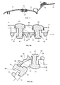
- Figure 1 shows an airbag cover 11 according to the present invention incorporating an emblem 13 formed by two independent parts and fixed to the cover 11 by means of a snap-fitting plate 17.
- the cover 11 includes a perforated line 9 by means of which it will break during deployment of the airbag. Once this occurs and as is shown in the right part of Figure 1 , the emblem 13 allows the part of the cover 11 separating during the exit of the airbag cushion to acquire a certain degree of bending, which is beneficial for preventing the release of parts of the cover that may injure the vehicle occupant.
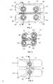
- Figures 2 and 3 along with Figures 5a and 5b show a first embodiment of the invention in which the emblem 13 is formed by two independent parts 21, 23, schematically shown in Figure 2 , with rounded rectangular shaped heads and a snap-fitting plate 17 shown in Figure 2 with a rectangular shape, and with a shape similar to that of a four-leaf clover in Figure 3 .
- Part 21 includes rods 41, 41' for its fixing to the snap-fitting plate 17 by means of snap-fitting.
- part 23 includes rods 43, 43' for its fixing by snap-fitting to the snap-fitting plate 17.
- the snap-fitting plate 17 has two elastic bodies 51, 51' with central holes 61, 61' to receive the rods 41, 41' of part 21 and two elastic bodies 53, 53' with two central holes 63, 63' to receive the rods 43, 43' of part 23.
- the rods 41, 41', 43, , 43' end with an enlarged body and the elastic bodies 51, 51', 53, 53' with the central holes 61, 61', 63, 63' of the plate 17 allow the passage through these holes of the enlarged bodies of the end parts of the rods 41, 41', 43, 43', but they prevent opposite movement.
- the invention comprises these specific snap-fitting means and any other equivalent means.
- the snap-fitting plate 17 is structured in a first area 31 in which the elastic bodies 51, 51' with the holes 61, 61' receiving the rods 41, 41' of the first part 21 of the emblem 13 are located, a second area 35 in which the elastic bodies 53, 53' with the holes 63, 63' receiving the rods 43, 43' of the second part 23 of the emblem 13 are located, and an intermediate area 33 between both, the central part 39 of which has less thickness than the rest.
- Figures 5a and 5b also show in greater detail that the cover 11 includes an offset area for the incorporation of the parts 21 and 23 on both sides of its central part 12 and the snap-fitting between the enlarged end body of the rods 41 and 43 and the elastic bodies 51, 53 which are arranged, respectively, around the holes 61 and 63 of the snap-fitting plate 17.
- the rods 41, 41', 43, 43' of the parts 21, 23 of the emblem 13 and the central points of the elastic bodies 51, 51', 53, 53' of the snap-fitting plate are arranged in the hypothetical corners of a rectangle, in the attempt that the dimensions are as small as possible, being compatible with the shape of the emblem 13.
- Figure 4 shows a second embodiment of the invention similar to the first embodiment, except that in the two parts 21, 23 of the emblem only one rod 41, 43 instead of two rods is incorporated and instead of having two elastic bodies in each area 31, 35 the snap-fitting plate only has one elastic body 51, 53 to receive said rods 41, 43.
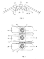
- Figures 6 and 7 show a third embodiment of the invention in which the emblem is formed by three independent parts 21, 23, 25, each of them including a rod 41, 43, 45 and a snap-fitting plate 17 which is structured in a first area 31 in which an elastic body 51 with a hole 61 for receiving the rod 41 is located, a second area 35 in which an elastic body 53 with a hole 63 for receiving the rod 43 is located and a third area in which an elastic body 55 with a hole 65 for receiving the rod 45 is located.
- Areas 31, 35, 39 are separated by intermediate areas 33, 37 with a central part having less thickness working, like in the other embodiments of the invention, as a bending area of the snap-fitting plate 17 during deployment of the airbag cushion, allowing relative movement between the three parts 21, 23, 25 of the emblem.
Landscapes
- Engineering & Computer Science (AREA)
- Mechanical Engineering (AREA)
- Air Bags (AREA)
Abstract
Description
- The present invention relates to an airbag cover for an automotive vehicle with an emblem fixed thereto, such as a logotype of the vehicle manufacturer, and more particularly with an emblem snap-fit to the cover.
-
US 2005/0067815 describes an Airbag cover according to the preamble of claim 1. - Different types of airbag covers are currently known which incorporate an emblem generally consisting of the logotype of the vehicle manufacturer, aiding in identifying its brand image.
- In one of these types, which include the proposals described in patent applications
US 2004/0174002 ,GB 2 403 693 DE 10148279 andDE 10 2004 046 866 , the airbag cover is made of a soft plastic, the emblem is also made of a soft plastic and the perforation line of the cover traverses the emblem. - In another one of these types, the airbag cover is made of a soft plastic, the emblem is made of a hard plastic usually with special coating providing it with a metallic appearance, and the perforation line is arranged surrounding the emblem so as to not traverse it.
- The fixing of the emblem to the airbag cover can be done in several manners.
- One of them is the fixing by means of welding, for example by means of ultrasonic welding. The problems involved with this type of fixing include those relating to complying with the welding quality requirements and to the suitable maintenance of the equipment used.
- Another one of these fixings is fixing the emblem to the cover using snap-fitting means. This type of fixing has the drawback that the snap-fitting plate confers excessive rigidity to the emblem-cover-snap-fitting plate assembly during the opening of the cover at the time of airbag deployment, making it difficult for the emblem to follow the bending of the cover, possibly causing it to break with the subsequent risk for the vehicle occupant.
- As described in patent document
US 5,775,721 , this drawback can be solved for the case of one-part emblems using a snap-fitting plate provided with holes or other means facilitating its deformation during the opening of the airbag cover, absorbing part of the energy generated and preventing the emblem from breaking. - However, this solution is not applicable to emblems formed by two or more parts and the present invention is aimed at providing a solution for this case.
- An object of the present invention is to allow the incorporation of emblems formed by two or more independent parts on the cover of an airbag module by simple fixing means without risks that parts of the emblem can be released, causing injuries to the vehicle occupant when the airbag cover breaks along the pre-established perforation lines so as to allow airbag deployment.
- This and other objects are achieved by providing an airbag cover for automotive vehicles with means for predetermining its breaking during the deployment of the airbag cushion, which incorporates an emblem formed by at least two independent parts which is fixed to the cover by means of the aid of one or more rods arranged on its inner face with a snap-fitting plate arranged inside the cover and comprising at least two areas, each of which includes snap-fitting means cooperating with said rods and an intermediate area between them which is configured such that it can work as a bending area of the snap-fitting plate during the deployment of the airbag cushion, allowing relative movement between the parts of the emblem.
- In a preferred embodiment, said intermediate area includes a part having less thickness than the rest, facilitating its deformation to be adapted to the movement of the cover during the deployment of the airbag cushion.
- In another preferred embodiment, the snap-fitting means of the snap-fitting plate consist of elastic bodies with central holes cooperating with rods with enlarged end parts allowing their passage through said holes but preventing movement in the opposite direction.
- In another preferred embodiment, the emblem has two parts each of which has a rod, and the snap-fitting part has two elastic bodies.
- In another preferred embodiment, the emblem has two parts each of which has two rods, and the snap-fitting part has four elastic bodies arranged such that their central points occupy the corners of a hypothetical rectangle.
- In another preferred embodiment, the emblem has two parts each of which has two rods, and the snap-fitting parts has four elastic bodies arranged such that their central points occupy the corners of a hypothetical rectangle.
- In another preferred embodiment, the emblem has three parts each of which has a rod, and the snap-fitting part has three elastic bodies.
- Other features and advantages of the present invention shall be understood from the following detailed description of an illustrative embodiment of its object in relation to the attached figures.
-
-
Figure 1 shows a sectional view of the airbag cover at rest in the left part and during deployment of the airbag cushion in the right part. -
Figure 2 shows a plan view from inside the airbag cover of the emblem-snap-fitting plate assembly according to a first embodiment of the present invention. -
Figure 3 shows a perspective view of a snap-fitting plate that can be used in the first embodiment of the present invention. -
Figure 4 shows a plan view from inside the airbag cover of the emblem-snap-fitting plate assembly according to a second embodiment of the present invention. -
Figure 5a shows a view according to the A-A section ofFigures 2 and 4 of the emblem-snap-fitting plate assembly according to the first and second embodiments of the present invention at rest. -
Figure 5b shows a view according to the A-A section ofFigures 2 and 4 of the emblem-snap-fitting plate assembly according to the first and second embodiments of the present invention during deployment of the airbag cushion. -
Figure 6 shows a cross-sectional view of the emblem-snap-fitting plate assembly according to a third embodiment of the present invention. -
Figure 7 shows a plan view from inside the airbag cover of the emblem-snap-fitting plate assembly according to the third embodiment of the present invention. -
Figure 1 shows anairbag cover 11 according to the present invention incorporating anemblem 13 formed by two independent parts and fixed to thecover 11 by means of a snap-fitting plate 17. - The
cover 11 includes a perforated line 9 by means of which it will break during deployment of the airbag. Once this occurs and as is shown in the right part ofFigure 1 , theemblem 13 allows the part of thecover 11 separating during the exit of the airbag cushion to acquire a certain degree of bending, which is beneficial for preventing the release of parts of the cover that may injure the vehicle occupant. -
Figures 2 and 3 along withFigures 5a and 5b show a first embodiment of the invention in which theemblem 13 is formed by twoindependent parts Figure 2 , with rounded rectangular shaped heads and a snap-fitting plate 17 shown inFigure 2 with a rectangular shape, and with a shape similar to that of a four-leaf clover inFigure 3 . -
Part 21 includesrods 41, 41' for its fixing to the snap-fitting plate 17 by means of snap-fitting. Similarly,part 23 includesrods 43, 43' for its fixing by snap-fitting to the snap-fitting plate 17. - The snap-
fitting plate 17 has twoelastic bodies 51, 51' withcentral holes 61, 61' to receive therods 41, 41' ofpart 21 and twoelastic bodies 53, 53' with twocentral holes 63, 63' to receive therods 43, 43' ofpart 23. - As can be seen in the Figures, the
rods elastic bodies central holes plate 17 allow the passage through these holes of the enlarged bodies of the end parts of therods - The snap-
fitting plate 17 is structured in afirst area 31 in which theelastic bodies 51, 51' with theholes 61, 61' receiving therods 41, 41' of thefirst part 21 of theemblem 13 are located, asecond area 35 in which theelastic bodies 53, 53' with theholes 63, 63' receiving therods 43, 43' of thesecond part 23 of theemblem 13 are located, and anintermediate area 33 between both, thecentral part 39 of which has less thickness than the rest. - According to
Figures 5a and 5b , it can be seen that this configuration of the snap-fitting plate 17 allows the bending of theemblem 13,cover 11 and snap-fitting plate 17 assembly when thecover 11 breaks so as to allow the exit of the airbag cushion. -
Figures 5a and 5b also show in greater detail that thecover 11 includes an offset area for the incorporation of theparts central part 12 and the snap-fitting between the enlarged end body of therods elastic bodies holes fitting plate 17. - In the embodiment of the invention being described, the
rods parts emblem 13 and the central points of theelastic bodies emblem 13. -
Figure 4 shows a second embodiment of the invention similar to the first embodiment, except that in the twoparts rod area elastic body rods -
Figures 6 and 7 show a third embodiment of the invention in which the emblem is formed by threeindependent parts rod fitting plate 17 which is structured in afirst area 31 in which anelastic body 51 with ahole 61 for receiving therod 41 is located, asecond area 35 in which anelastic body 53 with ahole 63 for receiving therod 43 is located and a third area in which anelastic body 55 with a hole 65 for receiving therod 45 is located.Areas intermediate areas fitting plate 17 during deployment of the airbag cushion, allowing relative movement between the threeparts - Any modifications comprised within the scope defined by the following claims can be introduced in the embodiments described above.
Claims (8)
- An airbag cover (11) for automotive vehicles comprising means to predetermine its breaking during deployment of the airbag cushion, incorporating an emblem (13) fixed to the cover (11) by means of the aid of one or more rods arranged on its inner face with a snap-fitting plate (17) arranged inside the cover (11), whereby:a) the emblem (13) is formed by at least two parts (21, 23);b) the snap-fitting plate (17) comprises at least two areas (31, 35), each of which includes snap-fitting means cooperating with the rods of each of said at least two parts (21, 23), characterized in that:- the two parts (21, 23) are independent and an intermediate area (33) between them is configured such that it can work as a bending area of the snap-fitting plate (17) during deployment of the airbag cushion, allowing relative movement between the parts (21,23) of the emblem (13).
- An airbag cover (11) for automotive vehicles according to claim 1, characterized in that said intermediate area (33) includes a part (39) having less thickness than the rest.
- An airbag cover (11) for automotive vehicles according to any of claims 1-2, characterized in that said snap-fitting means cooperating with said rods consist of elastic bodies with central holes.
- An airbag cover (11) for automotive vehicles according to claim 3, characterized in that the emblem (13) is formed by two independent parts (21,23) each of them including a rod (41,43) and in that the snap-fitting plate (17) includes two elastic bodies (51; 53) with central holes (61;63).
- An airbag cover (11) for automotive vehicles according to claim 3, characterized in that the emblem (13) is formed by two independent parts (21, 23), each of them including two rods (41, 41'; 43, 43'), and in that the snap-fitting plate (17) includes four elastic bodies (51, 51'; 53, 53') with central holes (61, 61'; 63, 63').
- An airbag cover (11) for automotive vehicles according to claim 5, characterized in that said rods (41, 41'; 43, 43') are arranged on the cover (11) in the hypothetical corners of a rectangle.
- An airbag cover (11) for automotive vehicles according to claim 5, characterized in that the snap-fitting plate (17) has a four-leaf clover shape, with said elastic bodies (51, 51': 53, 53') arranged in each of said leaves.
- An airbag cover (11) for automotive vehicles according to any of claims 1-3, characterized in that the emblem (13) is formed by three independent parts (21, 23, 25), each of them including a rod (41, 43, 45), and in that the snap-fitting plate (17) comprises three areas (31, 35, 39) with an elastic body (51, 53, 55) in each of them and two intermediate areas (33, 37) between them.
Priority Applications (4)
| Application Number | Priority Date | Filing Date | Title |
|---|---|---|---|
| EP07381031A EP1980454B1 (en) | 2007-04-10 | 2007-04-10 | Airbag cover with an emblem |
| DE602007004192T DE602007004192D1 (en) | 2007-04-10 | 2007-04-10 | Airbag cover with an emblem |
| AT07381031T ATE454294T1 (en) | 2007-04-10 | 2007-04-10 | AIRBAG COVER WITH AN EMBLEM |
| US12/082,075 US7775550B2 (en) | 2007-04-10 | 2008-04-08 | Airbag cover with an emblem |
Applications Claiming Priority (1)
| Application Number | Priority Date | Filing Date | Title |
|---|---|---|---|
| EP07381031A EP1980454B1 (en) | 2007-04-10 | 2007-04-10 | Airbag cover with an emblem |
Publications (2)
| Publication Number | Publication Date |
|---|---|
| EP1980454A1 EP1980454A1 (en) | 2008-10-15 |
| EP1980454B1 true EP1980454B1 (en) | 2010-01-06 |
Family
ID=38326999
Family Applications (1)
| Application Number | Title | Priority Date | Filing Date |
|---|---|---|---|
| EP07381031A Active EP1980454B1 (en) | 2007-04-10 | 2007-04-10 | Airbag cover with an emblem |
Country Status (4)
| Country | Link |
|---|---|
| US (1) | US7775550B2 (en) |
| EP (1) | EP1980454B1 (en) |
| AT (1) | ATE454294T1 (en) |
| DE (1) | DE602007004192D1 (en) |
Families Citing this family (12)
| Publication number | Priority date | Publication date | Assignee | Title |
|---|---|---|---|---|
| US8459713B2 (en) * | 2010-08-09 | 2013-06-11 | Autoliv Asp, Inc. | Assembly for attaching an emblem onto an airbag storage compartment cover |
| JP5494540B2 (en) * | 2011-03-25 | 2014-05-14 | 豊田合成株式会社 | Airbag cover |
| JP5921372B2 (en) * | 2012-03-27 | 2016-05-24 | タカタ株式会社 | Airbag device, fastening structure and fastening member |
| JP5950444B2 (en) * | 2012-04-27 | 2016-07-13 | 日本プラスト株式会社 | Cover body of airbag device |
| DE202014001873U1 (en) * | 2014-03-04 | 2015-06-08 | Dalphi Metal Espana S.A. | Assembly for the aesthetic design of a gas bag cover, gas bag cover, gas bag module and vehicle steering wheel, each having such an assembly |
| DE202014002912U1 (en) * | 2014-04-04 | 2015-07-07 | Dalphi Metal Espana, S.A. | Emblem assembly for connection to a gas bag cover, cover for a gas bag module, gas bag module and steering wheel with such a badge assembly |
| DE202014008757U1 (en) | 2014-11-05 | 2016-02-08 | Dalphi Metal Espana, S.A. | An emblem assembly for connection to a gas bag cover, gas bag cover, gas bag module, and vehicle steering wheel having such an emblem assembly |
| DE202018103540U1 (en) * | 2018-06-22 | 2019-10-07 | Dalphi Metal Espana, S.A. | Cover of a gas bag module, gas bag module and tool for producing such a cap |
| DE202018104588U1 (en) | 2018-08-09 | 2019-11-14 | Dalphi Metal Espana, S.A. | Cover cap for an airbag module and airbag module with such a cover cap |
| DE202018104587U1 (en) * | 2018-08-09 | 2019-11-19 | Dalphi Metal Espana, S.A. | Cover cap for an airbag module and airbag module with such a cover cap |
| DE102018218403B4 (en) * | 2018-10-26 | 2020-08-06 | Joyson Safety Systems Germany Gmbh | Arrangement for covering an airbag of a vehicle occupant restraint system |
| JP7179592B2 (en) * | 2018-11-26 | 2022-11-29 | 日本プラスト株式会社 | Airbag device cover body |
Family Cites Families (16)
| Publication number | Priority date | Publication date | Assignee | Title |
|---|---|---|---|---|
| US5851022A (en) * | 1995-03-31 | 1998-12-22 | Toyoda Gosei Co., Ltd. | Air bag pad with decorative device |
| US5678851A (en) * | 1995-04-28 | 1997-10-21 | Nihon Plast Co., Ltd. | Airbag module cover |
| DE29507890U1 (en) * | 1995-05-12 | 1995-07-27 | Trw Repa Gmbh, 73553 Alfdorf | Cover for an airbag restraint system in vehicles |
| JPH10119683A (en) * | 1996-10-17 | 1998-05-12 | Nippon Plast Co Ltd | Cover for air bag device |
| DE29706136U1 (en) * | 1997-03-24 | 1997-06-12 | Petri Ag, 63743 Aschaffenburg | Plaque attached to a base plate |
| US6168187B1 (en) * | 1997-07-01 | 2001-01-02 | Toyoda Gosei Co., Ltd. | Cover for an air bag |
| US6047984A (en) * | 1998-04-06 | 2000-04-11 | Larry J. Winget | Air bag cover and method of making same |
| US6099027A (en) * | 1998-06-29 | 2000-08-08 | Trw Inc. | Decorative emblem for air bag module cover |
| DE19829755B4 (en) * | 1998-07-03 | 2004-07-22 | Daimlerchrysler Ag | Airbag device for a motor vehicle |
| JP2001225703A (en) * | 1999-12-07 | 2001-08-21 | Tokai Rika Co Ltd | Mounting structure of plate body on pad cover |
| JP3833428B2 (en) * | 1999-12-14 | 2006-10-11 | 豊田合成株式会社 | Mounting structure for decorative products on molded products |
| JP4734702B2 (en) * | 2000-02-29 | 2011-07-27 | タカタ株式会社 | Method for manufacturing cover body of airbag device and cover body main body |
| DE10042527A1 (en) * | 2000-08-30 | 2002-03-28 | Audi Ag | Vehicle occupant protection device with an airbag module |
| DE20114507U1 (en) * | 2001-09-03 | 2002-01-24 | Trw Automotive Safety Sys Gmbh | Airbag module |
| JP3900005B2 (en) * | 2002-05-14 | 2007-04-04 | 豊田合成株式会社 | Airbag cover with ornament |
| US7097199B2 (en) * | 2003-09-25 | 2006-08-29 | Autoliv Asp, Inc. | Airbag cover emblem attachment apparatus and method |
-
2007
- 2007-04-10 EP EP07381031A patent/EP1980454B1/en active Active
- 2007-04-10 AT AT07381031T patent/ATE454294T1/en not_active IP Right Cessation
- 2007-04-10 DE DE602007004192T patent/DE602007004192D1/en active Active
-
2008
- 2008-04-08 US US12/082,075 patent/US7775550B2/en active Active
Also Published As
| Publication number | Publication date |
|---|---|
| EP1980454A1 (en) | 2008-10-15 |
| US7775550B2 (en) | 2010-08-17 |
| US20080252050A1 (en) | 2008-10-16 |
| DE602007004192D1 (en) | 2010-02-25 |
| ATE454294T1 (en) | 2010-01-15 |
Similar Documents
| Publication | Publication Date | Title |
|---|---|---|
| EP1980454B1 (en) | Airbag cover with an emblem | |
| EP2292476B1 (en) | Airbag cover and airbag device | |
| JP5493507B2 (en) | Vehicle armrest | |
| EP1504969A1 (en) | Instrument panel structure for vehicles | |
| US6543838B1 (en) | Vehicle door provided with pelvis thrust means | |
| JPH1059107A (en) | Instrument panel with airbag door | |
| DE19908702A1 (en) | Air bag apparatus in motor vehicle | |
| US20150375692A1 (en) | Vehicular interior component | |
| EP3833580B1 (en) | Covering cap for an airbag module and airbag module having such a covering cap | |
| JP2006088774A (en) | Side air bag device for rear seat | |
| CN107933449A (en) | Vehicle rope clamp | |
| DE60113212T2 (en) | Airbag retaining element | |
| JP2004268911A (en) | Decoration element | |
| EP3833581B1 (en) | Covering cap for an airbag module and airbag module having a covering cap of this type | |
| US7384061B2 (en) | Trim panel and a method of manufacture | |
| GB2070425A (en) | Arm-rest for a vehicle | |
| US10894518B2 (en) | Door trim | |
| DE102008005419B3 (en) | Airbag cover, has reinforcement element that is arranged at side of cover turned away from badge, and elastic material arranged between closure elements and reinforcement element, where elastic material is cover material | |
| CN107415787B (en) | Vehicle seat and headrest with dynamic crash energy management system | |
| JPH0885406A (en) | Structure for air bag door for automoible | |
| EP1923275A2 (en) | Airbag module for automotive vehicle steering wheels | |
| EP3060433B1 (en) | Seat arrangement | |
| JP2008120128A (en) | Clip mounting seat structure | |
| JP5145976B2 (en) | Vehicle door trim | |
| JP2601700Y2 (en) | instrument panel |
Legal Events
| Date | Code | Title | Description |
|---|---|---|---|
| PUAI | Public reference made under article 153(3) epc to a published international application that has entered the european phase |
Free format text: ORIGINAL CODE: 0009012 |
|
| AK | Designated contracting states |
Kind code of ref document: A1 Designated state(s): AT BE BG CH CY CZ DE DK EE ES FI FR GB GR HU IE IS IT LI LT LU LV MC MT NL PL PT RO SE SI SK TR |
|
| AX | Request for extension of the european patent |
Extension state: AL BA HR MK RS |
|
| 17P | Request for examination filed |
Effective date: 20090113 |
|
| R17P | Request for examination filed (corrected) |
Effective date: 20090109 |
|
| GRAP | Despatch of communication of intention to grant a patent |
Free format text: ORIGINAL CODE: EPIDOSNIGR1 |
|
| AKX | Designation fees paid |
Designated state(s): AT BE BG CH CY CZ DE DK EE ES FI FR GB GR HU IE IS IT LI LT LU LV MC MT NL PL PT RO SE SI SK TR |
|
| GRAS | Grant fee paid |
Free format text: ORIGINAL CODE: EPIDOSNIGR3 |
|
| GRAA | (expected) grant |
Free format text: ORIGINAL CODE: 0009210 |
|
| AK | Designated contracting states |
Kind code of ref document: B1 Designated state(s): AT BE BG CH CY CZ DE DK EE ES FI FR GB GR HU IE IS IT LI LT LU LV MC MT NL PL PT RO SE SI SK TR |
|
| REG | Reference to a national code |
Ref country code: GB Ref legal event code: FG4D |
|
| REG | Reference to a national code |
Ref country code: CH Ref legal event code: EP |
|
| REG | Reference to a national code |
Ref country code: IE Ref legal event code: FG4D |
|
| REF | Corresponds to: |
Ref document number: 602007004192 Country of ref document: DE Date of ref document: 20100225 Kind code of ref document: P |
|
| REG | Reference to a national code |
Ref country code: NL Ref legal event code: VDEP Effective date: 20100106 |
|
| PG25 | Lapsed in a contracting state [announced via postgrant information from national office to epo] |
Ref country code: SI Free format text: LAPSE BECAUSE OF FAILURE TO SUBMIT A TRANSLATION OF THE DESCRIPTION OR TO PAY THE FEE WITHIN THE PRESCRIBED TIME-LIMIT Effective date: 20100106 |
|
| LTIE | Lt: invalidation of european patent or patent extension |
Effective date: 20100106 |
|
| PG25 | Lapsed in a contracting state [announced via postgrant information from national office to epo] |
Ref country code: AT Free format text: LAPSE BECAUSE OF FAILURE TO SUBMIT A TRANSLATION OF THE DESCRIPTION OR TO PAY THE FEE WITHIN THE PRESCRIBED TIME-LIMIT Effective date: 20100106 |
|
| PG25 | Lapsed in a contracting state [announced via postgrant information from national office to epo] |
Ref country code: ES Free format text: LAPSE BECAUSE OF FAILURE TO SUBMIT A TRANSLATION OF THE DESCRIPTION OR TO PAY THE FEE WITHIN THE PRESCRIBED TIME-LIMIT Effective date: 20100417 Ref country code: IS Free format text: LAPSE BECAUSE OF FAILURE TO SUBMIT A TRANSLATION OF THE DESCRIPTION OR TO PAY THE FEE WITHIN THE PRESCRIBED TIME-LIMIT Effective date: 20100506 Ref country code: LT Free format text: LAPSE BECAUSE OF FAILURE TO SUBMIT A TRANSLATION OF THE DESCRIPTION OR TO PAY THE FEE WITHIN THE PRESCRIBED TIME-LIMIT Effective date: 20100106 Ref country code: NL Free format text: LAPSE BECAUSE OF FAILURE TO SUBMIT A TRANSLATION OF THE DESCRIPTION OR TO PAY THE FEE WITHIN THE PRESCRIBED TIME-LIMIT Effective date: 20100106 Ref country code: PT Free format text: LAPSE BECAUSE OF FAILURE TO SUBMIT A TRANSLATION OF THE DESCRIPTION OR TO PAY THE FEE WITHIN THE PRESCRIBED TIME-LIMIT Effective date: 20100506 |
|
| PG25 | Lapsed in a contracting state [announced via postgrant information from national office to epo] |
Ref country code: PL Free format text: LAPSE BECAUSE OF FAILURE TO SUBMIT A TRANSLATION OF THE DESCRIPTION OR TO PAY THE FEE WITHIN THE PRESCRIBED TIME-LIMIT Effective date: 20100106 Ref country code: LV Free format text: LAPSE BECAUSE OF FAILURE TO SUBMIT A TRANSLATION OF THE DESCRIPTION OR TO PAY THE FEE WITHIN THE PRESCRIBED TIME-LIMIT Effective date: 20100106 Ref country code: FI Free format text: LAPSE BECAUSE OF FAILURE TO SUBMIT A TRANSLATION OF THE DESCRIPTION OR TO PAY THE FEE WITHIN THE PRESCRIBED TIME-LIMIT Effective date: 20100106 |
|
| PG25 | Lapsed in a contracting state [announced via postgrant information from national office to epo] |
Ref country code: GR Free format text: LAPSE BECAUSE OF FAILURE TO SUBMIT A TRANSLATION OF THE DESCRIPTION OR TO PAY THE FEE WITHIN THE PRESCRIBED TIME-LIMIT Effective date: 20100407 Ref country code: SE Free format text: LAPSE BECAUSE OF FAILURE TO SUBMIT A TRANSLATION OF THE DESCRIPTION OR TO PAY THE FEE WITHIN THE PRESCRIBED TIME-LIMIT Effective date: 20100106 Ref country code: RO Free format text: LAPSE BECAUSE OF FAILURE TO SUBMIT A TRANSLATION OF THE DESCRIPTION OR TO PAY THE FEE WITHIN THE PRESCRIBED TIME-LIMIT Effective date: 20100106 Ref country code: BE Free format text: LAPSE BECAUSE OF FAILURE TO SUBMIT A TRANSLATION OF THE DESCRIPTION OR TO PAY THE FEE WITHIN THE PRESCRIBED TIME-LIMIT Effective date: 20100106 Ref country code: CY Free format text: LAPSE BECAUSE OF FAILURE TO SUBMIT A TRANSLATION OF THE DESCRIPTION OR TO PAY THE FEE WITHIN THE PRESCRIBED TIME-LIMIT Effective date: 20100106 Ref country code: EE Free format text: LAPSE BECAUSE OF FAILURE TO SUBMIT A TRANSLATION OF THE DESCRIPTION OR TO PAY THE FEE WITHIN THE PRESCRIBED TIME-LIMIT Effective date: 20100106 |
|
| PLBE | No opposition filed within time limit |
Free format text: ORIGINAL CODE: 0009261 |
|
| STAA | Information on the status of an ep patent application or granted ep patent |
Free format text: STATUS: NO OPPOSITION FILED WITHIN TIME LIMIT |
|
| PG25 | Lapsed in a contracting state [announced via postgrant information from national office to epo] |
Ref country code: SK Free format text: LAPSE BECAUSE OF FAILURE TO SUBMIT A TRANSLATION OF THE DESCRIPTION OR TO PAY THE FEE WITHIN THE PRESCRIBED TIME-LIMIT Effective date: 20100106 Ref country code: BG Free format text: LAPSE BECAUSE OF FAILURE TO SUBMIT A TRANSLATION OF THE DESCRIPTION OR TO PAY THE FEE WITHIN THE PRESCRIBED TIME-LIMIT Effective date: 20100406 Ref country code: CZ Free format text: LAPSE BECAUSE OF FAILURE TO SUBMIT A TRANSLATION OF THE DESCRIPTION OR TO PAY THE FEE WITHIN THE PRESCRIBED TIME-LIMIT Effective date: 20100106 Ref country code: MC Free format text: LAPSE BECAUSE OF NON-PAYMENT OF DUE FEES Effective date: 20100430 |
|
| 26N | No opposition filed |
Effective date: 20101007 |
|
| PG25 | Lapsed in a contracting state [announced via postgrant information from national office to epo] |
Ref country code: IE Free format text: LAPSE BECAUSE OF NON-PAYMENT OF DUE FEES Effective date: 20100410 Ref country code: DK Free format text: LAPSE BECAUSE OF FAILURE TO SUBMIT A TRANSLATION OF THE DESCRIPTION OR TO PAY THE FEE WITHIN THE PRESCRIBED TIME-LIMIT Effective date: 20100106 |
|
| PG25 | Lapsed in a contracting state [announced via postgrant information from national office to epo] |
Ref country code: IT Free format text: LAPSE BECAUSE OF FAILURE TO SUBMIT A TRANSLATION OF THE DESCRIPTION OR TO PAY THE FEE WITHIN THE PRESCRIBED TIME-LIMIT Effective date: 20100106 |
|
| PG25 | Lapsed in a contracting state [announced via postgrant information from national office to epo] |
Ref country code: MT Free format text: LAPSE BECAUSE OF FAILURE TO SUBMIT A TRANSLATION OF THE DESCRIPTION OR TO PAY THE FEE WITHIN THE PRESCRIBED TIME-LIMIT Effective date: 20100106 |
|
| REG | Reference to a national code |
Ref country code: CH Ref legal event code: PL |
|
| GBPC | Gb: european patent ceased through non-payment of renewal fee |
Effective date: 20110410 |
|
| PG25 | Lapsed in a contracting state [announced via postgrant information from national office to epo] |
Ref country code: LI Free format text: LAPSE BECAUSE OF NON-PAYMENT OF DUE FEES Effective date: 20110430 Ref country code: CH Free format text: LAPSE BECAUSE OF NON-PAYMENT OF DUE FEES Effective date: 20110430 |
|
| PG25 | Lapsed in a contracting state [announced via postgrant information from national office to epo] |
Ref country code: GB Free format text: LAPSE BECAUSE OF NON-PAYMENT OF DUE FEES Effective date: 20110410 |
|
| PG25 | Lapsed in a contracting state [announced via postgrant information from national office to epo] |
Ref country code: LU Free format text: LAPSE BECAUSE OF NON-PAYMENT OF DUE FEES Effective date: 20100410 Ref country code: HU Free format text: LAPSE BECAUSE OF FAILURE TO SUBMIT A TRANSLATION OF THE DESCRIPTION OR TO PAY THE FEE WITHIN THE PRESCRIBED TIME-LIMIT Effective date: 20100707 |
|
| PG25 | Lapsed in a contracting state [announced via postgrant information from national office to epo] |
Ref country code: TR Free format text: LAPSE BECAUSE OF FAILURE TO SUBMIT A TRANSLATION OF THE DESCRIPTION OR TO PAY THE FEE WITHIN THE PRESCRIBED TIME-LIMIT Effective date: 20100106 |
|
| REG | Reference to a national code |
Ref country code: FR Ref legal event code: PLFP Year of fee payment: 10 |
|
| REG | Reference to a national code |
Ref country code: FR Ref legal event code: PLFP Year of fee payment: 11 |
|
| REG | Reference to a national code |
Ref country code: FR Ref legal event code: PLFP Year of fee payment: 12 |
|
| P01 | Opt-out of the competence of the unified patent court (upc) registered |
Effective date: 20230528 |
|
| PGFP | Annual fee paid to national office [announced via postgrant information from national office to epo] |
Ref country code: FR Payment date: 20250310 Year of fee payment: 19 |
|
| PGFP | Annual fee paid to national office [announced via postgrant information from national office to epo] |
Ref country code: DE Payment date: 20250430 Year of fee payment: 19 |