EP1978536B1 - Elektromechanisches Schaltgerät - Google Patents
Elektromechanisches Schaltgerät Download PDFInfo
- Publication number
- EP1978536B1 EP1978536B1 EP07006443A EP07006443A EP1978536B1 EP 1978536 B1 EP1978536 B1 EP 1978536B1 EP 07006443 A EP07006443 A EP 07006443A EP 07006443 A EP07006443 A EP 07006443A EP 1978536 B1 EP1978536 B1 EP 1978536B1
- Authority
- EP
- European Patent Office
- Prior art keywords
- yoke
- bobbin
- switching device
- housing
- armature
- Prior art date
- Legal status (The legal status is an assumption and is not a legal conclusion. Google has not performed a legal analysis and makes no representation as to the accuracy of the status listed.)
- Not-in-force
Links
- 239000007858 starting material Substances 0.000 description 5
- 210000001331 nose Anatomy 0.000 description 3
- 239000004065 semiconductor Substances 0.000 description 3
- 239000000725 suspension Substances 0.000 description 2
- 238000004026 adhesive bonding Methods 0.000 description 1
- 230000005540 biological transmission Effects 0.000 description 1
- 230000006835 compression Effects 0.000 description 1
- 238000007906 compression Methods 0.000 description 1
- 238000002788 crimping Methods 0.000 description 1
- 238000009434 installation Methods 0.000 description 1
Images

Classifications
-
- H—ELECTRICITY
- H01—ELECTRIC ELEMENTS
- H01H—ELECTRIC SWITCHES; RELAYS; SELECTORS; EMERGENCY PROTECTIVE DEVICES
- H01H50/00—Details of electromagnetic relays
- H01H50/02—Bases; Casings; Covers
- H01H50/04—Mounting complete relay or separate parts of relay on a base or inside a case
- H01H50/041—Details concerning assembly of relays
- H01H50/045—Details particular to contactors
-
- H—ELECTRICITY
- H01—ELECTRIC ELEMENTS
- H01H—ELECTRIC SWITCHES; RELAYS; SELECTORS; EMERGENCY PROTECTIVE DEVICES
- H01H50/00—Details of electromagnetic relays
- H01H50/16—Magnetic circuit arrangements
- H01H50/36—Stationary parts of magnetic circuit, e.g. yoke
-
- H—ELECTRICITY
- H01—ELECTRIC ELEMENTS
- H01H—ELECTRIC SWITCHES; RELAYS; SELECTORS; EMERGENCY PROTECTIVE DEVICES
- H01H50/00—Details of electromagnetic relays
- H01H50/02—Bases; Casings; Covers
- H01H50/04—Mounting complete relay or separate parts of relay on a base or inside a case
- H01H50/041—Details concerning assembly of relays
- H01H2050/046—Assembling parts of a relay by using snap mounting techniques
-
- H—ELECTRICITY
- H01—ELECTRIC ELEMENTS
- H01H—ELECTRIC SWITCHES; RELAYS; SELECTORS; EMERGENCY PROTECTIVE DEVICES
- H01H50/00—Details of electromagnetic relays
- H01H50/44—Magnetic coils or windings
- H01H2050/446—Details of the insulating support of the coil, e.g. spool, bobbin, former
Definitions
- Electromechanical switching devices are, for example, emergency stop switches, contactors or soft starters in automation technology, which are usually connected between a power source and a consumer such as electrical machines or drives.
- Such switching devices contain mechanical switching elements for power transmission or interruption, which are electrically actuated via an existing electromagnet in the switching device.
- a switching element is called bypass.
- the semiconductor switch is galvanically bridged by mechanically closing the bypass in order to reduce the (semiconductor) power loss in the soft starter during continuous operation of the motor.
- a mechanical switching element includes a magnetic coil which is fixedly fixed in the switching device and a solenoid driven by the magnetic coil yoke and armature, wherein the yoke is also fixedly disposed in the housing or relative to the magnetic coil and the armature is movable.
- the armature is connected to a contact carrier, which carries movable contacts, which are brought in case of closing of the switching element in turn with housing-fixed contacts in touch.
- the switching device also contains springs or spring plates, among other things. All components of the electromechanical switching device must be arranged with respect to their geometric arrangement to each other clearly over the life mechanically and electrically reliable.
- the yoke is fixed with respect to the magnetic coil or the armature and the housing.
- the yoke in known products, such as the 3RW40 soft starter size S6 (MLFB: 3RW4055) or contactor 3RT1023 size S0 from Siemens AG, the yoke, as well as the solenoid coil or the bobbin, on the housing of the switching device by a so-called yoke suspension attached.
- the yoke suspension includes, for example, the yoke comprehensive snap clips, which are locked with the upper housing part.
- FIG. 5 shows such a switching device 110 roughly schematically.
- a coil 100 is mounted on an upper housing part 102, for example, clipped on this.
- a yoke 104 is placed on the coil 100.
- the yoke 104 is also mounted on the upper housing part 102 yoke holder 112 by the yoke holder 112 are snapped to the upper housing part by means of snap connections 114. Coil 100 and yoke 104 are thus both held on the upper housing part.
- Coil 100, yoke 104 and insert 106 are clamped by a lower housing part 108, which is snapped onto the upper housing part 102, between both fixed or stationary.
- the remaining components of the switching device 110 are in FIG. 4 for the sake of clarity not shown.
- WO 95/12891 A is an electromechanical switching device with firmly arranged in a housing fixed contacts and a movable contact bridge for bridging the fixed contacts, with a, the contact bridge bearing movable contact carrier, and with an acting on the contact carrier electromagnet.
- a fixed bobbin is arranged in the housing, an armature coupled to the contact carrier, a yoke cooperating with the armature, and a fixing device acting on the yoke and bobbin for fixing the yoke to the bobbin.
- the GB 1 581 751 A describes an electromechanical switching device with a two-part housing and a magnet armature and yoke, wherein armature, yoke and bobbin are attached via two spring clip on the housing.
- Object of the present invention is to improve an electromechanical switching device with respect to the fixed fixation of the yoke in the switching device.
- an electromechanical switching device with firmly arranged in a housing fixed contacts and a movable contact bridge for bridging the fixed contacts.
- the contact bridge is supported by a movable contact carrier.
- the contact carrier is moved by an electromagnet acting on it.
- the electromagnet comprises a coil body fastened to the housing of the switching device, an armature coupled to the contact carrier and a yoke cooperating with the armature.
- the electromechanical switching device has a fixing device, which acts on the yoke and bobbins and serves to fix the yoke on the bobbin.
- the yoke is thus also fixed with respect to the housing and the bobbin in a fixed position, but attached via the fixing device directly to the bobbin, and not attached to the housing.
- the assembly of the yoke and bobbin unit in the housing is facilitated and requires only a single fastening operation.
- the fixing device has a bracket attachable to the bobbin for the yoke.
- a yoke holder which also during pre-assembly fixed the yoke to the bobbin by means of the holder.
- the presence of the Jochhalters or its correct installation can be controlled even before assembly of the switching device and thus easier.
- the fixing device may have a latching after fixing of the yoke latch.
- the yoke or the fixing device then only have to be snapped or latched onto the bobbin or vice versa.
- An additional step such as screwing, gluing, crimping or the like is eliminated.
- the fixing device may be integral with the bobbin running, the yoke in the fixed state engaging behind latching noses.
- the yoke can be attached to the bobbin in a particularly simple manner by moving it towards the bobbin, with the latching noses in this case outwards, i. be moved from its rest position. Only when the yoke is fully pushed on do the snap-in lugs snap back into their original position, thus reaching behind the yoke and fixing it.
- the fixing device may comprise a cage enclosing the yoke in the fixed state between it and the bobbin, which has for example cross-shaped pressure elements. Each pressure element then exerts pressure in each case on the yoke in the direction of the bobbin out, whereby this is pressed centrally over the on the bobbin.
- Such a cage can be latched onto the bobbin. Even so, the attachment of the cage is solved in a particularly simple manner and requires no further work step, such as the above screwing etc.
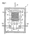
- FIG. 1 shows a highly simplified representation of a contactor 2 with a housing 4, which is cut to look into the interior of the contactor 2 can.
- a switching element 6 and an electromagnet 8 is arranged, which actuates the switching member 6.
- the switching element 6 comprises two, the wall of the housing 4 passing through fixed contacts 10a, b, which carry 12 each at their housing inner ends 12 contact buttons.
- the contact buttons 14 are each associated with further contact buttons 14, which are arranged on a movable contact 16.
- the movable contact 16 is mounted in a movable contact carrier 18.
- the electromagnet 8 comprises a bobbin 30, on which an electric coil 32 is wound. From the in FIG. 1 visible rear wall 34 of the housing 4 extends into the interior of the contactor 2 in, ie in FIG. 1 to the viewer, a part of the housing 4 in the form of a mounting tongue 36. On the mounting tongue 36 of the bobbin 30 is fixedly mounted, for example snapped, and thus fixed relative to the housing 4 fixed. In the bobbin 30 is with its central extension (in FIG. 1 not visible) introduced an E-shaped yoke 38, so that the two outer legs 40 of the yoke 38 laterally on the bobbin 30 over in the direction of the switching element 6 point.
- a yoke holder 42 includes the yoke 38 and fixes it on the bobbin 30 by the yoke holder 42 is fixedly attached to the bobbin 30, for example, snapped on this. The fixation comes close on the yoke 38 as short as possible, namely at the yoke 28 facing the end of the bobbin 30 at.
- the coil 32 is not energized and the armature 44 biased by a coil spring 48, which is supported on the armature 44 and on the mounting tongue 36, opposite to the arrow 46, ie in the opening direction of the contact buttons 14. He is therefore in his final position in OffenPosition.
- the contactor 2 is open, there is no electrical contact between the fixed contacts 10a, b.
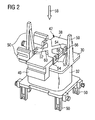
- FIG. 2 shows the bobbin 30 from FIG. 1 in a more detailed illustration together with the coil 32, the yoke 38 and the yoke holder 42.
- the yoke holder 42 is formed in the manner of a cage, at four points 52 on the bobbin 30 is attached.
- the fasteners are designed in the form of locking lugs 54, which are integrally formed on the bobbin and engage in corresponding openings 56 of the yoke holder 42 when it is pressed in the direction of arrow 58 during assembly on the bobbin 30 and the applied yoke 38.
- strained state of the yoke holder 42 via a pressure member 60 pressure in the direction of arrow 58 on the yoke 38 and presses it against the bobbin 30th
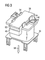
- FIG. 3 shows an alternative non-inventive embodiment of a bobbin 30, on which in turn latching noses 54 are formed. However, these do not serve as in FIG. 2 to mount a yoke holder 42, but act directly on the yoke 38 a. If the yoke 38 is applied during assembly in the direction of the arrow 58 on the bobbin 30, the locking lugs 54 deviate from the yoke 38 and rest only when this in the in FIG. 3 shown end position abuts the bobbin 30, behind the top 62 of the yoke holder 38 before to permanently attach this on the bobbin 30. In the FIG. 3 shown solution is opposite to in FIG. 2 shown solution suitable only for smaller holding down forces of the yoke 38 on the bobbin 30. For a separate yoke holder 42 in the embodiment according to. FIG. 3 unnecessary.
Landscapes
- Physics & Mathematics (AREA)
- Electromagnetism (AREA)
- Electromagnets (AREA)
Description
- Die Erfindung betrifft ein elektromechanisches Schaltgerät. Elektromechanische Schaltgeräte sind z.B. Not-Aus-Schalter, Schütze oder Sanftstarter in der Automatisierungstechnik, welche in der Regel zwischen einer Stromquelle und einem Verbraucher wie elektrischen Maschinen bzw. Antrieben geschaltet sind. Derartige Schaltgeräte enthalten mechanische Schaltglieder zur Stromübertragung bzw. -unterbrechung, welche über einen im Schaltgerät vorhandenen Elektromagneten elektrisch betätigt werden. Z.B. bei modernen Sanftstartern für Elektromotoren wird ein derartiges Schaltglied Bypass genannt. Im Falle eines vollständigen Durchschaltens eines Halbleiterschalters im Sanftstarter wird der Halbleiterschalter durch mechanisches Schließen des Bypasses galvanisch überbrückt, um die (Halbleiter-)Verlustleistung im Sanftstarter bei Dauerbetrieb des Motors reduzieren.
Ein mechanisches Schaltglied enthält eine Magnetspule, welche fest im Schaltgerät fixiert ist und einen von der Magnetspule angesteuerten magnetischen Kreis aus Joch und Anker, wobei das Joch ebenfalls im Gehäuse bzw. relativ zur Magnetspule fest angeordnet ist und der Anker beweglich ist. Der Anker ist mit einem Kontaktträger verbunden, welcher bewegliche Kontakte trägt, welche im Falle des Schließens des Schaltgliedes mit wiederum gehäusefesten Festkontakten in Berührung gebracht werden. Das Schaltgerät enthält auch unter anderem Federn bzw. Federteller. Alle Bauteile des Elektromechanischen Schaltgerätes müssen bezüglich ihrer geometrischen Anordnung zueinander eindeutig über die Lebensdauer mechanisch und elektrisch zuverlässig angeordnet werden. Im Besonderen ist hierbei das Joch ortsfest bezüglich der Magnetspule bzw. des Ankers und des Gehäuses zu befestigen.
Bei bekannten Produkten, wie z.B. dem Sanftstarter 3RW40 Baugröße S6 (MLFB:3RW4055) oder Schütz 3RT1023 Baugröße S0 der Firma Siemens AG wird das Joch, genau wie die Magnetspule bzw. der Spulenkörper, am Gehäuse des Schaltgeräts durch eine sogenannte Jochaufhängung befestigt. Die Jochaufhängung umfasst beispielsweise das Joch umfassende Schnappklammern, die mit dem Gehäuseoberteil verrastet werden.FIG 5 zeigt ein derartiges Schaltgerät 110 grob schematisch. Eine Spule 100 ist auf einem Gehäuseoberteil 102 montiert, z.B. auf dieses aufgeclipst. Auf die Spule 100 ist ein Joch 104 aufgelegt. Das Joch 104 ist Jochhalter 112 ebenfalls am Gehäuseoberteil 102 montiert, indem die Jochhalter 112 an das Gehäuseoberteil mit Hilfe von Schnappverbindungen 114 angeschnappt sind. Spule 100 und Joch 104 sind also beide am Gehäuseoberteil gehalten. - Es ist auch bekannt, das Joch auf den Spulenkörper aufzulegen und auf der dem Spulenkörper abgewandten Seite des Jochs ein Einlegeteil vorzusehen. Alle drei Komponenten werden dann zwischen einem Gehäuseunterteil und einem -oberteil fixiert, welche zusammengerastet sind. Das Gehäuseoberteil kann hierbei einstückig mit dem Spulenkörper ausgebildet sein. Eine derartige Anordnung ist als Schaltgerät 110 in
FIG 4 grob schematisch gezeigt. Eine Spule 100 ist hierbei auf einem Gehäuseoberteil 102 montiert bzw. einstückig mit diesem ausgeführt. Auf der gegenüberliegenden Seite der Spule 100 ist ein Joch 104 aufgelegt. Am Joch 104 ist ein Einlegeteil 106 angelegt. Spule 100, Joch 104 und Einlegeteil 106 sind durch ein Gehäuseunterteil 108, das auf das Gehäuseoberteil 102 aufgeschnappt ist, zwischen beiden verspannt bzw. ortsfest fixiert. Die restlichen Komponenten des Schaltgeräts 110 sind inFIG 4 der Übersichtlichkeit halber nicht dargestellt. - Die Nachteile der bekannten Lösungen sind, dass z.B. Schnapphaken für die Jochbefestigung durch Gehäuseteile im Gerät zur Verfügung stehen müssen, dass der Teileaufwand hoch ist, da für die Verschnappung separate Teile notwendig sind, dass die Jochhalterungen einen zusätzlichen Platzbedarf im Gerät beanspruchen und dass Montagefehler, z.B. das Vergessen eines Jochhalters bzw. einer Halteklammer auftreten können.
- Aus der
WO 95/12891 A - Die
GB 1 581 751 A - Aufgabe der vorliegenden Erfindung ist es, ein elektromechanisches Schaltgerät hinsichtlich der ortsfesten Fixierung des Jochs im Schaltgerät zu verbessern.
- Die Aufgabe wird gelöst durch ein elektromechanisches Schaltgerät mit fest in einem Gehäuse angeordneten Festkontakten und einer beweglichen Kontaktbrücke zur Überbrückung der Festkontakte. Die Kontaktbrücke ist hierbei von einem beweglichen Kontaktträger getragen. Der Kontaktträger wird bewegt von einem auf ihn einwirkenden Elektromagneten. Der Elektromagnet umfasst einem am Gehäuse des Schaltgeräts befestigten Spulenkörper, einen mit dem Kontaktträger bewegungsgekoppelten Anker und ein mit dem Anker zusammenwirkendes Joch. Erfindungsgemäß weist das elektromechanische Schaltgerät eine Fixiervorrichtung auf, welche an Joch und Spulenkörpern angreift und zur Fixierung des Jochs am Spulenkörper dient.
- Das Joch ist also ebenfalls bezüglich des Gehäuses und des Spulenkörpers in einer festen Lage fixiert, jedoch über die Fixiervorrichtung direkt am Spulenkörper, und nicht am Gehäuse befestigt. Somit entsteht eine Einheit aus Magnetspule und Joch, welche als separate Funktionseinheit in einer Vormontage bereits zusammengefügt werden kann. Die Montage der Einheit aus Joch und Spulenkörper im Gehäuse ist dadurch erleichtert und benötigt nur einen einzigen Befestigungsvorgang.
- Die Fixiervorrichtung weist eine am Spulenkörper anbringbare Halterung für das Joch auf. Somit existiert ein separates Bauteil, ein Jochhalter, welcher ebenfalls bei Vormontage das Joch am Spulenkörper mittels der Halterung fixiert. Das Vorhandensein des Jochhalters bzw. dessen korrekte Montage kann jedoch bereits vor Zusammenbau des Schaltgerätes und damit einfacher kontrolliert werden.
- Die Fixiervorrichtung kann eine nach Fixierung des Jochs einrastende Verrastung aufweisen. Das Joch bzw. die Fixiervorrichtung müssen dann lediglich auf den Spulenkörper oder umgekehrt aufgeschnappt bzw. eingerastet werden. Ein zusätzlicher Arbeitsschritt wie Verschrauben, Verkleben, Vercrimpen oder ähnliches entfällt.
- Die Fixiervorrichtung kann einstückig mit dem Spulenkörper ausgeführte, das Joch im fixierten Zustand hintergreifende Rastnasen aufweisen. Das Joch kann so besonders einfach am Spulenkörper befestigt werden, indem es auf den Spulenkörper zubewegt wird und die Rastnasen hierbei nach außen, d.h. aus ihrer Rastposition bewegt werden. Erst bei vollständig aufgedrücktem Joch schnappen die Rastnasen in ihre ursprüngliche Lage zurück, hintergreifen damit das Joch und fixieren es.
- Die Fixiervorrichtung kann einen das Joch im fixierten Zustand zwischen sich und dem Spulenkörper einschließenden Käfig umfassen, der beispielsweise kreuzförmig angeordnete Andruckelemente aufweist. Jedes Andruckelement übt dann jeweils für sich Druck auf das Joch in Richtung des Spulenkörpers hin aus, wodurch dieses zentral über den auf den Spulenkörper gedrückt wird.
- Ein derartiger Käfig kann auf den Spulenkörper aufrastbar sein. Auch so ist das Befestigen des Käfigs in besonders einfacher Weise gelöst und erfordert keinen weiteren Arbeitsschritt, wie das oben genannte Anschrauben etc..
- Für eine weitere Beschreibung der Erfindung wird auf die Ausführungsbeispiele der Zeichnungen verwiesen. Es zeigen, jeweils in einer schematischen Prinzipskizze:
- FIG 1
- ein elektromechanisches Schaltgerät, dessen Gehäuse aufgeschnitten ist,
- FIG 2
- eine Magnetspule mit Joch und aufgeschnappten Fixierkäfig,
- FIG 3
- eine Magnetspule mit angeformter Fixiervorrichtung,
- FIG 4
- eine Jochbefestigung gemäß Stand der Technik durch Verpressung zwischen Gehäusehälften,
- FIG 5
- eine alternative Jochbefestigung gemäß Stand der Technik durch Befestigung an einem Gehäuseteil.
-
FIG 1 zeigt in stark vereinfachter Darstellung einen Schaltschütz 2 mit einem Gehäuse 4, welches aufgeschnitten ist, um ins Innere des Schaltschützes 2 blicken zu können. Im Gehäuse 4 ist ein Schaltglied 6 und ein Elektromagnet 8 angeordnet, welcher das Schaltglied 6 betätigt. Das Schaltglied 6 umfasst zwei, die Wand des Gehäuses 4 durchsetzende Festkontakte 10a,b, welche jeweils an ihren gehäuseinneren Enden 12 Kontaktknöpfe 14 tragen. Den Kontaktknöpfen 14 sind jeweils weitere Kontaktknöpfe 14 zugeordnet, welche auf einem beweglichen Kontakt 16 angeordnet sind. Der bewegliche Kontakt 16 ist in einem beweglichen Kontaktträger 18 befestigt. - Der Elektromagnet 8 umfasst einen Spulenkörper 30, auf welchen eine elektrische Spule 32 aufgewickelt ist. Von der in
FIG 1 sichtbaren Rückwand 34 des Gehäuses 4 erstreckt sich in das Innere des Schaltschützes 2 hinein, also inFIG 1 auf den Betrachter zu, ein Teil des Gehäuses 4 in Form einer Montagezunge 36. Auf der Montagezunge 36 ist der Spulenkörper 30 fest angebracht, z.B. aufgeschnappt, und somit relativ zum Gehäuse 4 ortsfest fixiert. In den Spulenkörper 30 ist mit seinem Mittelfortsatz (inFIG 1 nicht sichtbar) ein E-förmiges Joch 38 eingeführt, so dass die beiden äußeren Schenkel 40 des Jochs 38 seitlich am Spulenkörper 30 vorbei in Richtung des Schaltgliedes 6 weisen. Ein Jochhalter 42 umfasst das Joch 38 und fixiert dieses auf dem Spulenkörper 30, indem der Jochhalter 42 fest am Spulenkörper 30 angebracht ist, z.B. auf diesen aufgeschnappt. Die Fixierung greift dabei nahe am Joch 38 auf möglichst kurzem Weg, nämlich an dem dem Joch 28 zugewandten Ende des Spulenkörpers 30 an. - Über die Montagezunge 36 sind also Spulenkörper 30, Spule 32, Joch 38 und Jochhalter 42 ortsfest zum Gehäuse 4 fixiert. Auf der dem Joch 38 gegenüberliegenden Seite des Spulenkörpers 30 ist ein E-förmiger Anker 44 angebracht, um zusammen mit dem Spulenkörper 30 einen magnetischen Kreis des Elektromagneten 8 zu bilden. Der Anker 44 ragt mit seinem mittleren Schenkel 41 in das Innere der Spule 32. Der Anker 44 ist fest mit dem Kontaktträger 18 verbunden und damit mit diesem und dem Kontakt 16 bzw. den Kontaktknöpfen 14 bewegungsgekoppelt. Der Anker 44 ist in bzw. entgegen der Richtung des Pfeils 46 bewegbar. In
FIG 1 ist die Spule 32 nicht bestromt und der Anker 44 durch eine Schraubenfeder 48, welche sich am Anker 44 und an der Montagezunge 36 abstützt, entgegen des Pfeils 46, also in Öffnungsrichtung der Kontaktknöpfe 14 vorgespannt. Er befindet sich also in seiner Endlage in OffenPosition. Der Schaltschütz 2 ist geöffnet, es besteht kein elektrischer Kontakt zwischen den Festkontakten 10a,b. - Durch Bestromen der Spule 32 wird in Joch 38 und Anker 44 ein Magnetkreis erzeugt, welcher den beweglichen Anker 44 relativ zum Gehäuse 4 in Richtung des Pfeils 46 bewegt und damit die Kontaktknöpfe 14 in gegenseitigen Kontakt bringt. Der elektrische Kontakt zwischen den Festkontakten 10a,b ist somit hergestellt.
-
FIG 2 zeigt den Spulenkörper 30 ausFIG 1 in einer detaillierteren Darstellung zusammen mit der Spule 32, dem Joch 38 und dem Jochhalter 42. Im Gegensatz zur stark vereinfachten Darstellung inFIG 1 sind inFIG 2 , mehrere am Spulenkörper 30 angeformte Strukturelemente 50 sichtbar, welche sämtlich der Verankerung des Spulenkörpers 30 im Gehäuse 4 dienen. - Außerdem ist zu erkennen, dass der Jochhalter 42 nach Art eines Käfigs ausgebildet ist, der an vier Stellen 52 am Spulenkörper 30 befestigt ist. Die Befestigungen sind in Form von Rastnasen 54 ausgeführt, welche am Spulenkörper angeformt sind und in entsprechende Öffnungen 56 des Jochhalters 42 eingreifen, wenn dieser in Richtung des Pfeils 58 bei der Montage auf den Spulenkörper 30 bzw. das aufgelegte Joch 38 aufgepresst wird. Im in
FIG 2 dargestellten, verspannten Zustand übt der Jochhalter 42 über ein Druckteil 60 Druck in Richtung des Pfeils 58 auf das Joch 38 auf und presst dieses gegen den Spulenkörper 30. -
FIG 3 zeigt eine alternative nicht erfindungsgemäße Ausführungsform eines Spulenkörpers 30, an welchem wiederum Rastnasen 54 angeformt sind. Diese dienen jedoch nun nicht dazu, wie inFIG 2 einen Jochhalter 42 zu befestigen, sondern wirken direkt auf das Joch 38 ein. Wird das Joch 38 bei der Montage in Richtung des Pfeils 58 auf den Spulenkörper 30 aufgebracht, weichen die Rastnasen 54 vor dem Joch 38 aus und rasten erst, wenn dieses in der inFIG 3 gezeigten Endposition am Spulenkörper 30 anliegt, hinter die Oberseite 62 des Jochhalters 38 vor, um diesen dauerhaft auf dem Spulenkörper 30 zu befestigen. Die inFIG 3 gezeigte Lösung ist gegenüber der inFIG 2 gezeigten Lösung nur für kleinere Niederhaltekräfte des Jochs 38 auf dem Spulenkörper 30 geeignet. Dafür ist ein separater Jochhalter 42 in der Ausführungsform gem.FIG 3 nicht notwendig.
Claims (5)
- Elektromechanisches Schaltgerät (2) mit fest in einem Gehäuse (4) angeordneten Festkontakten (10a,b), und einer beweglichen Kontaktbrücke (16) zur Überbrückung der Festkontakte (10a,b), mit einem, die Kontaktbrücke (16) tragenden beweglichen Kontaktträger (18), mit einem auf den Kontaktträger (18) wirkenden Elektromagneten (8), umfassend einen am Gehäuse (4) befestigten Spulenkörper (30), einen mit dem Kontaktträger (18) bewegungsgekoppelten Anker (44), ein mit dem Anker (44) zusammenwirkendes Joch (38), und eine an Joch (38) und Spulenkörper (30) angreifende Fixiervorrichtung (42,54) zur Fixierung des Jochs (38) am Spulenkörper (30), dadurch gekennzeichnet, daß die Fixiervorrichtung (42,54) eine am Spulenkörper (30) anbringbare Halterung (42) für das Joch (38) aufweist.
- Schaltgerät (2) nach Anspruch 1, bei dem die Fixiervorrichtung (42,54) eine nach Fixierung des Jochs einrastende Verrastung (54,56) aufweist.
- Schaltgerät (2) nach Anspruch 1 oder 2, bei dem die Fixiervorrichtung (42,54) einstückig mit dem Spulenkörper (30) ausgeführte, das Joch (38) im fixierten Zustand hintergreifende Rastnasen (54) aufweist.
- Schaltgerät (2) nach einem der vorhergehenden Ansprüche, bei dem die Fixiervorrichtung (42,54) einen das Joch (38) im fixierten Zustand zwischen sich und dem Spulenkörper (30) einschließenden Käfig (42) umfasst.
- Schaltgerät (2) nach Anspruch 4, bei dem der Käfig (42) auf den Spulenkörper (30) aufrastbar ist.
Priority Applications (3)
| Application Number | Priority Date | Filing Date | Title |
|---|---|---|---|
| EP07006443A EP1978536B1 (de) | 2007-03-28 | 2007-03-28 | Elektromechanisches Schaltgerät |
| CN2007101954750A CN101276706B (zh) | 2007-03-28 | 2007-11-30 | 电动机械的开关装置 |
| US12/000,495 US7737811B2 (en) | 2007-03-28 | 2007-12-13 | Electromechanical switching device |
Applications Claiming Priority (1)
| Application Number | Priority Date | Filing Date | Title |
|---|---|---|---|
| EP07006443A EP1978536B1 (de) | 2007-03-28 | 2007-03-28 | Elektromechanisches Schaltgerät |
Publications (2)
| Publication Number | Publication Date |
|---|---|
| EP1978536A1 EP1978536A1 (de) | 2008-10-08 |
| EP1978536B1 true EP1978536B1 (de) | 2012-11-28 |
Family
ID=38187578
Family Applications (1)
| Application Number | Title | Priority Date | Filing Date |
|---|---|---|---|
| EP07006443A Not-in-force EP1978536B1 (de) | 2007-03-28 | 2007-03-28 | Elektromechanisches Schaltgerät |
Country Status (3)
| Country | Link |
|---|---|
| US (1) | US7737811B2 (de) |
| EP (1) | EP1978536B1 (de) |
| CN (1) | CN101276706B (de) |
Families Citing this family (4)
| Publication number | Priority date | Publication date | Assignee | Title |
|---|---|---|---|---|
| US8508321B2 (en) * | 2010-08-17 | 2013-08-13 | Song Chuan Precision Co., Ltd. | Relay with multiple coils |
| EP2437278B1 (de) * | 2010-09-30 | 2013-05-15 | Hager-Electro SAS | Zusammenbau eines Motors eines mehrpoligen Schutzschalters |
| CN212161708U (zh) * | 2020-02-26 | 2020-12-15 | 华为技术有限公司 | 触头装置及电磁开关 |
| CN211980527U (zh) * | 2020-05-29 | 2020-11-20 | 比亚迪股份有限公司 | 继电器 |
Citations (2)
| Publication number | Priority date | Publication date | Assignee | Title |
|---|---|---|---|---|
| GB1581751A (en) * | 1976-04-28 | 1980-12-17 | Bbc Brown Boveri & Cie | Electromagnetic contactors |
| WO1995012891A1 (en) * | 1993-11-04 | 1995-05-11 | Asea Brown Boveri Ab | Electromagnetically operated electric switching device |
Family Cites Families (10)
| Publication number | Priority date | Publication date | Assignee | Title |
|---|---|---|---|---|
| NL132206C (de) * | 1962-04-24 | |||
| US3215800A (en) * | 1962-07-02 | 1965-11-02 | Square D Co | Electromagnetic relay and contact carrier assembly therefor |
| DE2651927C2 (de) * | 1976-11-13 | 1983-03-31 | Brown, Boveri & Cie Ag, 6800 Mannheim | Wechselstromschütz mit einer Aufnahmevorrichtung für einen Magnetkern mit Kurzschlußringen |
| DE59406665D1 (de) * | 1993-10-22 | 1998-09-17 | Bf Patent Ag | Blendeneinheit |
| DE19611997A1 (de) * | 1996-03-26 | 1997-10-02 | Siemens Ag | Elektromagnetisches Relais |
| CN2416598Y (zh) * | 2000-02-17 | 2001-01-24 | 正泰集团公司 | 交流接触器 |
| DE10013314C2 (de) * | 2000-03-17 | 2002-01-17 | Siemens Ag | Elektromagnetisches Schaltgerät, insbesondere Schütz |
| DE10013353C2 (de) * | 2000-03-17 | 2002-02-07 | Siemens Ag | Elekromagnetisches Schaltgerät, insbesondere Schütz |
| US6661321B1 (en) * | 2002-08-30 | 2003-12-09 | Tendex Electric Co., Ltd. | Electromagnetic switch |
| WO2005101441A1 (de) * | 2004-04-13 | 2005-10-27 | Siemens Aktiengesellschaft | Spulenkörper für schaltgeräte |
-
2007
- 2007-03-28 EP EP07006443A patent/EP1978536B1/de not_active Not-in-force
- 2007-11-30 CN CN2007101954750A patent/CN101276706B/zh not_active Expired - Fee Related
- 2007-12-13 US US12/000,495 patent/US7737811B2/en active Active
Patent Citations (2)
| Publication number | Priority date | Publication date | Assignee | Title |
|---|---|---|---|---|
| GB1581751A (en) * | 1976-04-28 | 1980-12-17 | Bbc Brown Boveri & Cie | Electromagnetic contactors |
| WO1995012891A1 (en) * | 1993-11-04 | 1995-05-11 | Asea Brown Boveri Ab | Electromagnetically operated electric switching device |
Also Published As
| Publication number | Publication date |
|---|---|
| CN101276706B (zh) | 2010-12-01 |
| CN101276706A (zh) | 2008-10-01 |
| EP1978536A1 (de) | 2008-10-08 |
| US20080258851A1 (en) | 2008-10-23 |
| US7737811B2 (en) | 2010-06-15 |
Similar Documents
| Publication | Publication Date | Title |
|---|---|---|
| EP2831900B1 (de) | Gepoltes elektromagnetisches relais und verfahren zu seiner herstellung | |
| DE1256300B (de) | Schaltschuetz | |
| DE69604679T2 (de) | Polarisiertes elektromagnetisches relais | |
| DE102008057555A1 (de) | Relais mit Flip-Flop-Feder | |
| DE602005000652T2 (de) | Elektromagnetisches Relais | |
| EP1978536B1 (de) | Elektromechanisches Schaltgerät | |
| EP3443571B1 (de) | Stromlos monostabile elektromagnetische stellvorrichtung und verwendung einer solchen | |
| EP2645386A1 (de) | Relais mit verbesserten Isolationseigenschaften | |
| EP0593526A1 (de) | Elektromagnetisches relais. | |
| EP3149758A1 (de) | Schaltgerät mit modularem hilfsschalterblock | |
| DE102012106330B4 (de) | Spulenkern für elektromagnetischen Antrieb und selbiger sowie Verfahren zu dessen Herstellung | |
| DE1807319A1 (de) | Relais | |
| EP3408855A1 (de) | Elektromagnetische stellvorrichtung und verwendung einer solchen | |
| EP1901326B1 (de) | Motorstarter | |
| DE202004013965U1 (de) | Ein Permanentmagnet-Auslösemechanismus vom Solenoidtyp für ein Überlastrelais vom elektronischen Typ | |
| DE202014010575U1 (de) | Leistungsrelais für ein Fahrzeug | |
| DE3443556C2 (de) | Elektrisches Schaltgerät | |
| DE102009036054A1 (de) | Kontaktanordnung für ein elektormagnetisches Schaltgerät | |
| EP1085549A2 (de) | Bistabiles Schütz | |
| DE102016011341A1 (de) | Hochvoltschaltschützanordnung für ein Kraftfahrzeug und Verfahren zum Überführen einer Hochvoltschaltschützanordnung zwischen einem geöffneten und einem geschlossenen Zustand | |
| DE102018109864B4 (de) | Relais | |
| EP2743940B1 (de) | Elektromagnetischer Aktor | |
| EP2652861A2 (de) | Magnethalteeinrichtung | |
| DE102012006450A1 (de) | Relais mit zwangsgeführten Kontakten | |
| DE19635275C1 (de) | Polarisiertes Relais |
Legal Events
| Date | Code | Title | Description |
|---|---|---|---|
| PUAI | Public reference made under article 153(3) epc to a published international application that has entered the european phase |
Free format text: ORIGINAL CODE: 0009012 |
|
| 17P | Request for examination filed |
Effective date: 20070910 |
|
| AK | Designated contracting states |
Kind code of ref document: A1 Designated state(s): AT BE BG CH CY CZ DE DK EE ES FI FR GB GR HU IE IS IT LI LT LU LV MC MT NL PL PT RO SE SI SK TR |
|
| AX | Request for extension of the european patent |
Extension state: AL BA HR MK RS |
|
| 17Q | First examination report despatched |
Effective date: 20090202 |
|
| AKX | Designation fees paid |
Designated state(s): AT BE BG CH CY CZ DE DK EE ES FI FR GB GR HU IE IS IT LI LT LU LV MC MT NL PL PT RO SE SI SK TR |
|
| REG | Reference to a national code |
Ref country code: DE Ref legal event code: R079 Ref document number: 502007010937 Country of ref document: DE Free format text: PREVIOUS MAIN CLASS: H01H0050040000 Ipc: H01H0050360000 |
|
| GRAP | Despatch of communication of intention to grant a patent |
Free format text: ORIGINAL CODE: EPIDOSNIGR1 |
|
| RIC1 | Information provided on ipc code assigned before grant |
Ipc: H01H 50/04 20060101ALI20120523BHEP Ipc: H01H 50/36 20060101AFI20120523BHEP |
|
| GRAS | Grant fee paid |
Free format text: ORIGINAL CODE: EPIDOSNIGR3 |
|
| GRAA | (expected) grant |
Free format text: ORIGINAL CODE: 0009210 |
|
| AK | Designated contracting states |
Kind code of ref document: B1 Designated state(s): AT BE BG CH CY CZ DE DK EE ES FI FR GB GR HU IE IS IT LI LT LU LV MC MT NL PL PT RO SE SI SK TR |
|
| REG | Reference to a national code |
Ref country code: GB Ref legal event code: FG4D Free format text: NOT ENGLISH |
|
| REG | Reference to a national code |
Ref country code: CH Ref legal event code: EP |
|
| REG | Reference to a national code |
Ref country code: AT Ref legal event code: REF Ref document number: 586546 Country of ref document: AT Kind code of ref document: T Effective date: 20121215 |
|
| REG | Reference to a national code |
Ref country code: IE Ref legal event code: FG4D Free format text: LANGUAGE OF EP DOCUMENT: GERMAN |
|
| REG | Reference to a national code |
Ref country code: DE Ref legal event code: R096 Ref document number: 502007010937 Country of ref document: DE Effective date: 20130117 |
|
| REG | Reference to a national code |
Ref country code: SE Ref legal event code: TRGR |
|
| RAP2 | Party data changed (patent owner data changed or rights of a patent transferred) |
Owner name: SIEMENS AKTIENGESELLSCHAFT |
|
| REG | Reference to a national code |
Ref country code: NL Ref legal event code: VDEP Effective date: 20121128 |
|
| REG | Reference to a national code |
Ref country code: LT Ref legal event code: MG4D |
|
| PG25 | Lapsed in a contracting state [announced via postgrant information from national office to epo] |
Ref country code: LT Free format text: LAPSE BECAUSE OF FAILURE TO SUBMIT A TRANSLATION OF THE DESCRIPTION OR TO PAY THE FEE WITHIN THE PRESCRIBED TIME-LIMIT Effective date: 20121128 Ref country code: ES Free format text: LAPSE BECAUSE OF FAILURE TO SUBMIT A TRANSLATION OF THE DESCRIPTION OR TO PAY THE FEE WITHIN THE PRESCRIBED TIME-LIMIT Effective date: 20130311 Ref country code: FI Free format text: LAPSE BECAUSE OF FAILURE TO SUBMIT A TRANSLATION OF THE DESCRIPTION OR TO PAY THE FEE WITHIN THE PRESCRIBED TIME-LIMIT Effective date: 20121128 |
|
| PG25 | Lapsed in a contracting state [announced via postgrant information from national office to epo] |
Ref country code: GR Free format text: LAPSE BECAUSE OF FAILURE TO SUBMIT A TRANSLATION OF THE DESCRIPTION OR TO PAY THE FEE WITHIN THE PRESCRIBED TIME-LIMIT Effective date: 20130301 Ref country code: PL Free format text: LAPSE BECAUSE OF FAILURE TO SUBMIT A TRANSLATION OF THE DESCRIPTION OR TO PAY THE FEE WITHIN THE PRESCRIBED TIME-LIMIT Effective date: 20121128 Ref country code: LV Free format text: LAPSE BECAUSE OF FAILURE TO SUBMIT A TRANSLATION OF THE DESCRIPTION OR TO PAY THE FEE WITHIN THE PRESCRIBED TIME-LIMIT Effective date: 20121128 Ref country code: CY Free format text: LAPSE BECAUSE OF FAILURE TO SUBMIT A TRANSLATION OF THE DESCRIPTION OR TO PAY THE FEE WITHIN THE PRESCRIBED TIME-LIMIT Effective date: 20121128 Ref country code: SI Free format text: LAPSE BECAUSE OF FAILURE TO SUBMIT A TRANSLATION OF THE DESCRIPTION OR TO PAY THE FEE WITHIN THE PRESCRIBED TIME-LIMIT Effective date: 20121128 Ref country code: PT Free format text: LAPSE BECAUSE OF FAILURE TO SUBMIT A TRANSLATION OF THE DESCRIPTION OR TO PAY THE FEE WITHIN THE PRESCRIBED TIME-LIMIT Effective date: 20130328 |
|
| PG25 | Lapsed in a contracting state [announced via postgrant information from national office to epo] |
Ref country code: SK Free format text: LAPSE BECAUSE OF FAILURE TO SUBMIT A TRANSLATION OF THE DESCRIPTION OR TO PAY THE FEE WITHIN THE PRESCRIBED TIME-LIMIT Effective date: 20121128 Ref country code: DK Free format text: LAPSE BECAUSE OF FAILURE TO SUBMIT A TRANSLATION OF THE DESCRIPTION OR TO PAY THE FEE WITHIN THE PRESCRIBED TIME-LIMIT Effective date: 20121128 Ref country code: CZ Free format text: LAPSE BECAUSE OF FAILURE TO SUBMIT A TRANSLATION OF THE DESCRIPTION OR TO PAY THE FEE WITHIN THE PRESCRIBED TIME-LIMIT Effective date: 20121128 Ref country code: EE Free format text: LAPSE BECAUSE OF FAILURE TO SUBMIT A TRANSLATION OF THE DESCRIPTION OR TO PAY THE FEE WITHIN THE PRESCRIBED TIME-LIMIT Effective date: 20121128 Ref country code: BG Free format text: LAPSE BECAUSE OF FAILURE TO SUBMIT A TRANSLATION OF THE DESCRIPTION OR TO PAY THE FEE WITHIN THE PRESCRIBED TIME-LIMIT Effective date: 20130228 |
|
| PG25 | Lapsed in a contracting state [announced via postgrant information from national office to epo] |
Ref country code: NL Free format text: LAPSE BECAUSE OF FAILURE TO SUBMIT A TRANSLATION OF THE DESCRIPTION OR TO PAY THE FEE WITHIN THE PRESCRIBED TIME-LIMIT Effective date: 20121128 Ref country code: RO Free format text: LAPSE BECAUSE OF FAILURE TO SUBMIT A TRANSLATION OF THE DESCRIPTION OR TO PAY THE FEE WITHIN THE PRESCRIBED TIME-LIMIT Effective date: 20121128 |
|
| BERE | Be: lapsed |
Owner name: SIEMENS A.G. Effective date: 20130331 |
|
| PLBE | No opposition filed within time limit |
Free format text: ORIGINAL CODE: 0009261 |
|
| STAA | Information on the status of an ep patent application or granted ep patent |
Free format text: STATUS: NO OPPOSITION FILED WITHIN TIME LIMIT |
|
| PG25 | Lapsed in a contracting state [announced via postgrant information from national office to epo] |
Ref country code: MC Free format text: LAPSE BECAUSE OF NON-PAYMENT OF DUE FEES Effective date: 20130331 |
|
| REG | Reference to a national code |
Ref country code: CH Ref legal event code: PL |
|
| 26N | No opposition filed |
Effective date: 20130829 |
|
| GBPC | Gb: european patent ceased through non-payment of renewal fee |
Effective date: 20130328 |
|
| REG | Reference to a national code |
Ref country code: DE Ref legal event code: R097 Ref document number: 502007010937 Country of ref document: DE Effective date: 20130829 |
|
| REG | Reference to a national code |
Ref country code: IE Ref legal event code: MM4A |
|
| PG25 | Lapsed in a contracting state [announced via postgrant information from national office to epo] |
Ref country code: CH Free format text: LAPSE BECAUSE OF NON-PAYMENT OF DUE FEES Effective date: 20130331 Ref country code: BE Free format text: LAPSE BECAUSE OF NON-PAYMENT OF DUE FEES Effective date: 20130331 Ref country code: GB Free format text: LAPSE BECAUSE OF NON-PAYMENT OF DUE FEES Effective date: 20130328 Ref country code: LI Free format text: LAPSE BECAUSE OF NON-PAYMENT OF DUE FEES Effective date: 20130331 Ref country code: IE Free format text: LAPSE BECAUSE OF NON-PAYMENT OF DUE FEES Effective date: 20130328 |
|
| REG | Reference to a national code |
Ref country code: AT Ref legal event code: MM01 Ref document number: 586546 Country of ref document: AT Kind code of ref document: T Effective date: 20130328 |
|
| PG25 | Lapsed in a contracting state [announced via postgrant information from national office to epo] |
Ref country code: MT Free format text: LAPSE BECAUSE OF FAILURE TO SUBMIT A TRANSLATION OF THE DESCRIPTION OR TO PAY THE FEE WITHIN THE PRESCRIBED TIME-LIMIT Effective date: 20121128 |
|
| PG25 | Lapsed in a contracting state [announced via postgrant information from national office to epo] |
Ref country code: AT Free format text: LAPSE BECAUSE OF NON-PAYMENT OF DUE FEES Effective date: 20130328 |
|
| PG25 | Lapsed in a contracting state [announced via postgrant information from national office to epo] |
Ref country code: TR Free format text: LAPSE BECAUSE OF FAILURE TO SUBMIT A TRANSLATION OF THE DESCRIPTION OR TO PAY THE FEE WITHIN THE PRESCRIBED TIME-LIMIT Effective date: 20121128 |
|
| PG25 | Lapsed in a contracting state [announced via postgrant information from national office to epo] |
Ref country code: LU Free format text: LAPSE BECAUSE OF NON-PAYMENT OF DUE FEES Effective date: 20130328 Ref country code: HU Free format text: LAPSE BECAUSE OF FAILURE TO SUBMIT A TRANSLATION OF THE DESCRIPTION OR TO PAY THE FEE WITHIN THE PRESCRIBED TIME-LIMIT; INVALID AB INITIO Effective date: 20070328 |
|
| REG | Reference to a national code |
Ref country code: FR Ref legal event code: PLFP Year of fee payment: 10 |
|
| PG25 | Lapsed in a contracting state [announced via postgrant information from national office to epo] |
Ref country code: IS Free format text: LAPSE BECAUSE OF FAILURE TO SUBMIT A TRANSLATION OF THE DESCRIPTION OR TO PAY THE FEE WITHIN THE PRESCRIBED TIME-LIMIT Effective date: 20121128 |
|
| REG | Reference to a national code |
Ref country code: FR Ref legal event code: PLFP Year of fee payment: 11 |
|
| REG | Reference to a national code |
Ref country code: FR Ref legal event code: PLFP Year of fee payment: 12 |
|
| PGFP | Annual fee paid to national office [announced via postgrant information from national office to epo] |
Ref country code: SE Payment date: 20220308 Year of fee payment: 16 Ref country code: IT Payment date: 20220322 Year of fee payment: 16 Ref country code: FR Payment date: 20220324 Year of fee payment: 16 |
|
| PGFP | Annual fee paid to national office [announced via postgrant information from national office to epo] |
Ref country code: DE Payment date: 20220518 Year of fee payment: 16 |
|
| P01 | Opt-out of the competence of the unified patent court (upc) registered |
Effective date: 20230510 |
|
| REG | Reference to a national code |
Ref country code: DE Ref legal event code: R119 Ref document number: 502007010937 Country of ref document: DE |
|
| REG | Reference to a national code |
Ref country code: SE Ref legal event code: EUG |
|
| PG25 | Lapsed in a contracting state [announced via postgrant information from national office to epo] |
Ref country code: SE Free format text: LAPSE BECAUSE OF NON-PAYMENT OF DUE FEES Effective date: 20230329 Ref country code: FR Free format text: LAPSE BECAUSE OF NON-PAYMENT OF DUE FEES Effective date: 20230331 Ref country code: DE Free format text: LAPSE BECAUSE OF NON-PAYMENT OF DUE FEES Effective date: 20231003 |
|
| PG25 | Lapsed in a contracting state [announced via postgrant information from national office to epo] |
Ref country code: IT Free format text: LAPSE BECAUSE OF NON-PAYMENT OF DUE FEES Effective date: 20230328 |