EP1978536B1 - Appareil de commutation électromécanique - Google Patents
Appareil de commutation électromécanique Download PDFInfo
- Publication number
- EP1978536B1 EP1978536B1 EP07006443A EP07006443A EP1978536B1 EP 1978536 B1 EP1978536 B1 EP 1978536B1 EP 07006443 A EP07006443 A EP 07006443A EP 07006443 A EP07006443 A EP 07006443A EP 1978536 B1 EP1978536 B1 EP 1978536B1
- Authority
- EP
- European Patent Office
- Prior art keywords
- yoke
- bobbin
- switching device
- housing
- armature
- Prior art date
- Legal status (The legal status is an assumption and is not a legal conclusion. Google has not performed a legal analysis and makes no representation as to the accuracy of the status listed.)
- Not-in-force
Links
- 239000007858 starting material Substances 0.000 description 5
- 210000001331 nose Anatomy 0.000 description 3
- 239000004065 semiconductor Substances 0.000 description 3
- 239000000725 suspension Substances 0.000 description 2
- 238000004026 adhesive bonding Methods 0.000 description 1
- 230000005540 biological transmission Effects 0.000 description 1
- 230000006835 compression Effects 0.000 description 1
- 238000007906 compression Methods 0.000 description 1
- 238000002788 crimping Methods 0.000 description 1
- 238000009434 installation Methods 0.000 description 1
Images

Classifications
-
- H—ELECTRICITY
- H01—ELECTRIC ELEMENTS
- H01H—ELECTRIC SWITCHES; RELAYS; SELECTORS; EMERGENCY PROTECTIVE DEVICES
- H01H50/00—Details of electromagnetic relays
- H01H50/02—Bases; Casings; Covers
- H01H50/04—Mounting complete relay or separate parts of relay on a base or inside a case
- H01H50/041—Details concerning assembly of relays
- H01H50/045—Details particular to contactors
-
- H—ELECTRICITY
- H01—ELECTRIC ELEMENTS
- H01H—ELECTRIC SWITCHES; RELAYS; SELECTORS; EMERGENCY PROTECTIVE DEVICES
- H01H50/00—Details of electromagnetic relays
- H01H50/16—Magnetic circuit arrangements
- H01H50/36—Stationary parts of magnetic circuit, e.g. yoke
-
- H—ELECTRICITY
- H01—ELECTRIC ELEMENTS
- H01H—ELECTRIC SWITCHES; RELAYS; SELECTORS; EMERGENCY PROTECTIVE DEVICES
- H01H50/00—Details of electromagnetic relays
- H01H50/02—Bases; Casings; Covers
- H01H50/04—Mounting complete relay or separate parts of relay on a base or inside a case
- H01H50/041—Details concerning assembly of relays
- H01H2050/046—Assembling parts of a relay by using snap mounting techniques
-
- H—ELECTRICITY
- H01—ELECTRIC ELEMENTS
- H01H—ELECTRIC SWITCHES; RELAYS; SELECTORS; EMERGENCY PROTECTIVE DEVICES
- H01H50/00—Details of electromagnetic relays
- H01H50/44—Magnetic coils or windings
- H01H2050/446—Details of the insulating support of the coil, e.g. spool, bobbin, former
Definitions
- Electromechanical switching devices are, for example, emergency stop switches, contactors or soft starters in automation technology, which are usually connected between a power source and a consumer such as electrical machines or drives.
- Such switching devices contain mechanical switching elements for power transmission or interruption, which are electrically actuated via an existing electromagnet in the switching device.
- a switching element is called bypass.
- the semiconductor switch is galvanically bridged by mechanically closing the bypass in order to reduce the (semiconductor) power loss in the soft starter during continuous operation of the motor.
- a mechanical switching element includes a magnetic coil which is fixedly fixed in the switching device and a solenoid driven by the magnetic coil yoke and armature, wherein the yoke is also fixedly disposed in the housing or relative to the magnetic coil and the armature is movable.
- the armature is connected to a contact carrier, which carries movable contacts, which are brought in case of closing of the switching element in turn with housing-fixed contacts in touch.
- the switching device also contains springs or spring plates, among other things. All components of the electromechanical switching device must be arranged with respect to their geometric arrangement to each other clearly over the life mechanically and electrically reliable.
- the yoke is fixed with respect to the magnetic coil or the armature and the housing.
- the yoke in known products, such as the 3RW40 soft starter size S6 (MLFB: 3RW4055) or contactor 3RT1023 size S0 from Siemens AG, the yoke, as well as the solenoid coil or the bobbin, on the housing of the switching device by a so-called yoke suspension attached.
- the yoke suspension includes, for example, the yoke comprehensive snap clips, which are locked with the upper housing part.
- FIG. 5 shows such a switching device 110 roughly schematically.
- a coil 100 is mounted on an upper housing part 102, for example, clipped on this.
- a yoke 104 is placed on the coil 100.
- the yoke 104 is also mounted on the upper housing part 102 yoke holder 112 by the yoke holder 112 are snapped to the upper housing part by means of snap connections 114. Coil 100 and yoke 104 are thus both held on the upper housing part.
- Coil 100, yoke 104 and insert 106 are clamped by a lower housing part 108, which is snapped onto the upper housing part 102, between both fixed or stationary.
- the remaining components of the switching device 110 are in FIG. 4 for the sake of clarity not shown.
- WO 95/12891 A is an electromechanical switching device with firmly arranged in a housing fixed contacts and a movable contact bridge for bridging the fixed contacts, with a, the contact bridge bearing movable contact carrier, and with an acting on the contact carrier electromagnet.
- a fixed bobbin is arranged in the housing, an armature coupled to the contact carrier, a yoke cooperating with the armature, and a fixing device acting on the yoke and bobbin for fixing the yoke to the bobbin.
- the GB 1 581 751 A describes an electromechanical switching device with a two-part housing and a magnet armature and yoke, wherein armature, yoke and bobbin are attached via two spring clip on the housing.
- Object of the present invention is to improve an electromechanical switching device with respect to the fixed fixation of the yoke in the switching device.
- an electromechanical switching device with firmly arranged in a housing fixed contacts and a movable contact bridge for bridging the fixed contacts.
- the contact bridge is supported by a movable contact carrier.
- the contact carrier is moved by an electromagnet acting on it.
- the electromagnet comprises a coil body fastened to the housing of the switching device, an armature coupled to the contact carrier and a yoke cooperating with the armature.
- the electromechanical switching device has a fixing device, which acts on the yoke and bobbins and serves to fix the yoke on the bobbin.
- the yoke is thus also fixed with respect to the housing and the bobbin in a fixed position, but attached via the fixing device directly to the bobbin, and not attached to the housing.
- the assembly of the yoke and bobbin unit in the housing is facilitated and requires only a single fastening operation.
- the fixing device has a bracket attachable to the bobbin for the yoke.
- a yoke holder which also during pre-assembly fixed the yoke to the bobbin by means of the holder.
- the presence of the Jochhalters or its correct installation can be controlled even before assembly of the switching device and thus easier.
- the fixing device may have a latching after fixing of the yoke latch.
- the yoke or the fixing device then only have to be snapped or latched onto the bobbin or vice versa.
- An additional step such as screwing, gluing, crimping or the like is eliminated.
- the fixing device may be integral with the bobbin running, the yoke in the fixed state engaging behind latching noses.
- the yoke can be attached to the bobbin in a particularly simple manner by moving it towards the bobbin, with the latching noses in this case outwards, i. be moved from its rest position. Only when the yoke is fully pushed on do the snap-in lugs snap back into their original position, thus reaching behind the yoke and fixing it.
- the fixing device may comprise a cage enclosing the yoke in the fixed state between it and the bobbin, which has for example cross-shaped pressure elements. Each pressure element then exerts pressure in each case on the yoke in the direction of the bobbin out, whereby this is pressed centrally over the on the bobbin.
- Such a cage can be latched onto the bobbin. Even so, the attachment of the cage is solved in a particularly simple manner and requires no further work step, such as the above screwing etc.
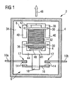
- FIG. 1 shows a highly simplified representation of a contactor 2 with a housing 4, which is cut to look into the interior of the contactor 2 can.
- a switching element 6 and an electromagnet 8 is arranged, which actuates the switching member 6.
- the switching element 6 comprises two, the wall of the housing 4 passing through fixed contacts 10a, b, which carry 12 each at their housing inner ends 12 contact buttons.
- the contact buttons 14 are each associated with further contact buttons 14, which are arranged on a movable contact 16.
- the movable contact 16 is mounted in a movable contact carrier 18.
- the electromagnet 8 comprises a bobbin 30, on which an electric coil 32 is wound. From the in FIG. 1 visible rear wall 34 of the housing 4 extends into the interior of the contactor 2 in, ie in FIG. 1 to the viewer, a part of the housing 4 in the form of a mounting tongue 36. On the mounting tongue 36 of the bobbin 30 is fixedly mounted, for example snapped, and thus fixed relative to the housing 4 fixed. In the bobbin 30 is with its central extension (in FIG. 1 not visible) introduced an E-shaped yoke 38, so that the two outer legs 40 of the yoke 38 laterally on the bobbin 30 over in the direction of the switching element 6 point.
- a yoke holder 42 includes the yoke 38 and fixes it on the bobbin 30 by the yoke holder 42 is fixedly attached to the bobbin 30, for example, snapped on this. The fixation comes close on the yoke 38 as short as possible, namely at the yoke 28 facing the end of the bobbin 30 at.
- the coil 32 is not energized and the armature 44 biased by a coil spring 48, which is supported on the armature 44 and on the mounting tongue 36, opposite to the arrow 46, ie in the opening direction of the contact buttons 14. He is therefore in his final position in OffenPosition.
- the contactor 2 is open, there is no electrical contact between the fixed contacts 10a, b.
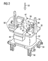
- FIG. 2 shows the bobbin 30 from FIG. 1 in a more detailed illustration together with the coil 32, the yoke 38 and the yoke holder 42.
- the yoke holder 42 is formed in the manner of a cage, at four points 52 on the bobbin 30 is attached.
- the fasteners are designed in the form of locking lugs 54, which are integrally formed on the bobbin and engage in corresponding openings 56 of the yoke holder 42 when it is pressed in the direction of arrow 58 during assembly on the bobbin 30 and the applied yoke 38.
- strained state of the yoke holder 42 via a pressure member 60 pressure in the direction of arrow 58 on the yoke 38 and presses it against the bobbin 30th
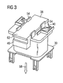
- FIG. 3 shows an alternative non-inventive embodiment of a bobbin 30, on which in turn latching noses 54 are formed. However, these do not serve as in FIG. 2 to mount a yoke holder 42, but act directly on the yoke 38 a. If the yoke 38 is applied during assembly in the direction of the arrow 58 on the bobbin 30, the locking lugs 54 deviate from the yoke 38 and rest only when this in the in FIG. 3 shown end position abuts the bobbin 30, behind the top 62 of the yoke holder 38 before to permanently attach this on the bobbin 30. In the FIG. 3 shown solution is opposite to in FIG. 2 shown solution suitable only for smaller holding down forces of the yoke 38 on the bobbin 30. For a separate yoke holder 42 in the embodiment according to. FIG. 3 unnecessary.
Landscapes
- Physics & Mathematics (AREA)
- Electromagnetism (AREA)
- Electromagnets (AREA)
Claims (5)
- Appareil de commutation électromécanique (2) comprenant des contacts fixes (10a, b) disposés de manière stationnaire dans un boîtier (4), et un pont de contact mobile (16) destiné à ponter les contacts fixes (10a, b), comprenant un porte-contacts mobile (18) portant le pont de contact (16), comprenant un électroaimant (8) agissant sur le porte-contacts (18), comprenant un corps de bobine (30) fixé sur le boîtier (4), un induit (44) couplé par mouvement au porte-contacts (18), une culasse (38) coopérant avec l'induit (44), et un dispositif de fixation (42, 54) ayant prise sur la culasse (38) et le corps de bobine (30) pour la fixation de la culasse (38) sur le corps de bobine (30), caractérisé en ce que le dispositif de fixation (42, 54) présente une attache (42) pouvant être installée sur le corps de bobine (30) pour la culasse (38).
- Appareil de commutation (2) selon la revendication 1, dans lequel le dispositif de fixation (42, 54) présente un dispositif d'enclenchement (54, 56) s'enclenchant après la fixation de la culasse.
- Appareil de commutation (2) selon la revendication 1 ou 2, dans lequel le dispositif de fixation (42, 54) présente des ergots d'enclenchement (54) réalisés d'une seule pièce avec le corps de bobine (30), ayant prise par derrière dans la culasse (38) à l'état fixé.
- Appareil de commutation (2) selon l'une quelconque des revendications précédentes, dans lequel le dispositif de fixation (42, 54) comprend une cage (42) entourant la culasse (38) à l'état fixé entre lui-même et le corps de bobine (30).
- Appareil de commutation (2) selon la revendication 4, dans lequel la cage (42) est enclenchable sur le corps de bobine (30).
Priority Applications (3)
| Application Number | Priority Date | Filing Date | Title |
|---|---|---|---|
| EP07006443A EP1978536B1 (fr) | 2007-03-28 | 2007-03-28 | Appareil de commutation électromécanique |
| CN2007101954750A CN101276706B (zh) | 2007-03-28 | 2007-11-30 | 电动机械的开关装置 |
| US12/000,495 US7737811B2 (en) | 2007-03-28 | 2007-12-13 | Electromechanical switching device |
Applications Claiming Priority (1)
| Application Number | Priority Date | Filing Date | Title |
|---|---|---|---|
| EP07006443A EP1978536B1 (fr) | 2007-03-28 | 2007-03-28 | Appareil de commutation électromécanique |
Publications (2)
| Publication Number | Publication Date |
|---|---|
| EP1978536A1 EP1978536A1 (fr) | 2008-10-08 |
| EP1978536B1 true EP1978536B1 (fr) | 2012-11-28 |
Family
ID=38187578
Family Applications (1)
| Application Number | Title | Priority Date | Filing Date |
|---|---|---|---|
| EP07006443A Not-in-force EP1978536B1 (fr) | 2007-03-28 | 2007-03-28 | Appareil de commutation électromécanique |
Country Status (3)
| Country | Link |
|---|---|
| US (1) | US7737811B2 (fr) |
| EP (1) | EP1978536B1 (fr) |
| CN (1) | CN101276706B (fr) |
Families Citing this family (2)
| Publication number | Priority date | Publication date | Assignee | Title |
|---|---|---|---|---|
| US8508321B2 (en) * | 2010-08-17 | 2013-08-13 | Song Chuan Precision Co., Ltd. | Relay with multiple coils |
| EP2437278B1 (fr) * | 2010-09-30 | 2013-05-15 | Hager-Electro SAS | Assemblage d'un moteur de contacteur multipolaire |
Citations (2)
| Publication number | Priority date | Publication date | Assignee | Title |
|---|---|---|---|---|
| GB1581751A (en) * | 1976-04-28 | 1980-12-17 | Bbc Brown Boveri & Cie | Electromagnetic contactors |
| WO1995012891A1 (fr) * | 1993-11-04 | 1995-05-11 | Asea Brown Boveri Ab | Commutateur electrique a commande electromagnetique |
Family Cites Families (10)
| Publication number | Priority date | Publication date | Assignee | Title |
|---|---|---|---|---|
| NL291054A (fr) * | 1962-04-24 | |||
| US3215800A (en) * | 1962-07-02 | 1965-11-02 | Square D Co | Electromagnetic relay and contact carrier assembly therefor |
| DE7635899U1 (de) * | 1976-11-13 | 1977-03-03 | Brown, Boveri & Cie Ag, 6800 Mannheim | Aufnahmevorrichtung fuer einen magnetkern mit kurzschlussringen und eine spule |
| ATE169735T1 (de) * | 1993-10-22 | 1998-08-15 | Bf Patent Ag | Blendeneinheit |
| DE19611997A1 (de) * | 1996-03-26 | 1997-10-02 | Siemens Ag | Elektromagnetisches Relais |
| CN2416598Y (zh) * | 2000-02-17 | 2001-01-24 | 正泰集团公司 | 交流接触器 |
| DE10013314C2 (de) * | 2000-03-17 | 2002-01-17 | Siemens Ag | Elektromagnetisches Schaltgerät, insbesondere Schütz |
| DE10013353C2 (de) * | 2000-03-17 | 2002-02-07 | Siemens Ag | Elekromagnetisches Schaltgerät, insbesondere Schütz |
| US6661321B1 (en) * | 2002-08-30 | 2003-12-09 | Tendex Electric Co., Ltd. | Electromagnetic switch |
| WO2005101441A1 (fr) * | 2004-04-13 | 2005-10-27 | Siemens Aktiengesellschaft | Corps de bobine pour appareils electriques |
-
2007
- 2007-03-28 EP EP07006443A patent/EP1978536B1/fr not_active Not-in-force
- 2007-11-30 CN CN2007101954750A patent/CN101276706B/zh not_active Expired - Fee Related
- 2007-12-13 US US12/000,495 patent/US7737811B2/en active Active
Patent Citations (2)
| Publication number | Priority date | Publication date | Assignee | Title |
|---|---|---|---|---|
| GB1581751A (en) * | 1976-04-28 | 1980-12-17 | Bbc Brown Boveri & Cie | Electromagnetic contactors |
| WO1995012891A1 (fr) * | 1993-11-04 | 1995-05-11 | Asea Brown Boveri Ab | Commutateur electrique a commande electromagnetique |
Also Published As
| Publication number | Publication date |
|---|---|
| CN101276706A (zh) | 2008-10-01 |
| EP1978536A1 (fr) | 2008-10-08 |
| US7737811B2 (en) | 2010-06-15 |
| CN101276706B (zh) | 2010-12-01 |
| US20080258851A1 (en) | 2008-10-23 |
Similar Documents
| Publication | Publication Date | Title |
|---|---|---|
| DE602005000652T2 (de) | Elektromagnetisches Relais | |
| DE1267309B (de) | Elektrisches Schuetz, bei dem Kontaktbruecke und Festkontakte als Baueinheit ausgebildet sind | |
| DE1256300B (de) | Schaltschuetz | |
| DE102008057555A1 (de) | Relais mit Flip-Flop-Feder | |
| EP3443571B1 (fr) | Dispositif de réglage électromagnétique monostable sans courant et utilisation d'un tel dispositif | |
| WO1993001608A1 (fr) | Relais electromagnetique | |
| EP1978536B1 (fr) | Appareil de commutation électromécanique | |
| EP1901326B1 (fr) | Démarreur de moteur | |
| DE112019002137T5 (de) | Elektromechanischer Schalter mit beweglichem Kontakt und Dämpfer | |
| EP1264325B1 (fr) | Appareil de commutation electromagnetique, en particulier contacteur electromagnetique | |
| EP2645386A1 (fr) | Relais doté de propriétés d'isolation améliorées | |
| EP3408855A1 (fr) | Dispositif de réglage électromagnétique et utilisation de celui-ci | |
| EP0802552B1 (fr) | Interrupteur électrique à déclenchement par manque de tension | |
| WO2013017182A1 (fr) | Relais électromagnétique | |
| EP3149758A1 (fr) | Dispositif de commutation à bloc de commutation auxiliaire modulaire | |
| DE1807319A1 (de) | Relais | |
| DE102016011341A1 (de) | Hochvoltschaltschützanordnung für ein Kraftfahrzeug und Verfahren zum Überführen einer Hochvoltschaltschützanordnung zwischen einem geöffneten und einem geschlossenen Zustand | |
| DE102012106330B4 (de) | Spulenkern für elektromagnetischen Antrieb und selbiger sowie Verfahren zu dessen Herstellung | |
| DE3443556C2 (de) | Elektrisches Schaltgerät | |
| EP1085549A2 (fr) | Contacteur bistable | |
| DE202014010575U1 (de) | Leistungsrelais für ein Fahrzeug | |
| AT404522B (de) | Elektromagnetisch gesteuerte schaltvorrichtung mit öffnungspolen | |
| EP2743940B1 (fr) | Actionneur électromagnétique | |
| DE202004013965U1 (de) | Ein Permanentmagnet-Auslösemechanismus vom Solenoidtyp für ein Überlastrelais vom elektronischen Typ | |
| WO2011015409A1 (fr) | Agencement de contacts pour un appareil électromagnétique de commutation |
Legal Events
| Date | Code | Title | Description |
|---|---|---|---|
| PUAI | Public reference made under article 153(3) epc to a published international application that has entered the european phase |
Free format text: ORIGINAL CODE: 0009012 |
|
| 17P | Request for examination filed |
Effective date: 20070910 |
|
| AK | Designated contracting states |
Kind code of ref document: A1 Designated state(s): AT BE BG CH CY CZ DE DK EE ES FI FR GB GR HU IE IS IT LI LT LU LV MC MT NL PL PT RO SE SI SK TR |
|
| AX | Request for extension of the european patent |
Extension state: AL BA HR MK RS |
|
| 17Q | First examination report despatched |
Effective date: 20090202 |
|
| AKX | Designation fees paid |
Designated state(s): AT BE BG CH CY CZ DE DK EE ES FI FR GB GR HU IE IS IT LI LT LU LV MC MT NL PL PT RO SE SI SK TR |
|
| REG | Reference to a national code |
Ref country code: DE Ref legal event code: R079 Ref document number: 502007010937 Country of ref document: DE Free format text: PREVIOUS MAIN CLASS: H01H0050040000 Ipc: H01H0050360000 |
|
| GRAP | Despatch of communication of intention to grant a patent |
Free format text: ORIGINAL CODE: EPIDOSNIGR1 |
|
| RIC1 | Information provided on ipc code assigned before grant |
Ipc: H01H 50/04 20060101ALI20120523BHEP Ipc: H01H 50/36 20060101AFI20120523BHEP |
|
| GRAS | Grant fee paid |
Free format text: ORIGINAL CODE: EPIDOSNIGR3 |
|
| GRAA | (expected) grant |
Free format text: ORIGINAL CODE: 0009210 |
|
| AK | Designated contracting states |
Kind code of ref document: B1 Designated state(s): AT BE BG CH CY CZ DE DK EE ES FI FR GB GR HU IE IS IT LI LT LU LV MC MT NL PL PT RO SE SI SK TR |
|
| REG | Reference to a national code |
Ref country code: GB Ref legal event code: FG4D Free format text: NOT ENGLISH |
|
| REG | Reference to a national code |
Ref country code: CH Ref legal event code: EP |
|
| REG | Reference to a national code |
Ref country code: AT Ref legal event code: REF Ref document number: 586546 Country of ref document: AT Kind code of ref document: T Effective date: 20121215 |
|
| REG | Reference to a national code |
Ref country code: IE Ref legal event code: FG4D Free format text: LANGUAGE OF EP DOCUMENT: GERMAN |
|
| REG | Reference to a national code |
Ref country code: DE Ref legal event code: R096 Ref document number: 502007010937 Country of ref document: DE Effective date: 20130117 |
|
| REG | Reference to a national code |
Ref country code: SE Ref legal event code: TRGR |
|
| RAP2 | Party data changed (patent owner data changed or rights of a patent transferred) |
Owner name: SIEMENS AKTIENGESELLSCHAFT |
|
| REG | Reference to a national code |
Ref country code: NL Ref legal event code: VDEP Effective date: 20121128 |
|
| REG | Reference to a national code |
Ref country code: LT Ref legal event code: MG4D |
|
| PG25 | Lapsed in a contracting state [announced via postgrant information from national office to epo] |
Ref country code: LT Free format text: LAPSE BECAUSE OF FAILURE TO SUBMIT A TRANSLATION OF THE DESCRIPTION OR TO PAY THE FEE WITHIN THE PRESCRIBED TIME-LIMIT Effective date: 20121128 Ref country code: ES Free format text: LAPSE BECAUSE OF FAILURE TO SUBMIT A TRANSLATION OF THE DESCRIPTION OR TO PAY THE FEE WITHIN THE PRESCRIBED TIME-LIMIT Effective date: 20130311 Ref country code: FI Free format text: LAPSE BECAUSE OF FAILURE TO SUBMIT A TRANSLATION OF THE DESCRIPTION OR TO PAY THE FEE WITHIN THE PRESCRIBED TIME-LIMIT Effective date: 20121128 |
|
| PG25 | Lapsed in a contracting state [announced via postgrant information from national office to epo] |
Ref country code: GR Free format text: LAPSE BECAUSE OF FAILURE TO SUBMIT A TRANSLATION OF THE DESCRIPTION OR TO PAY THE FEE WITHIN THE PRESCRIBED TIME-LIMIT Effective date: 20130301 Ref country code: PL Free format text: LAPSE BECAUSE OF FAILURE TO SUBMIT A TRANSLATION OF THE DESCRIPTION OR TO PAY THE FEE WITHIN THE PRESCRIBED TIME-LIMIT Effective date: 20121128 Ref country code: LV Free format text: LAPSE BECAUSE OF FAILURE TO SUBMIT A TRANSLATION OF THE DESCRIPTION OR TO PAY THE FEE WITHIN THE PRESCRIBED TIME-LIMIT Effective date: 20121128 Ref country code: CY Free format text: LAPSE BECAUSE OF FAILURE TO SUBMIT A TRANSLATION OF THE DESCRIPTION OR TO PAY THE FEE WITHIN THE PRESCRIBED TIME-LIMIT Effective date: 20121128 Ref country code: SI Free format text: LAPSE BECAUSE OF FAILURE TO SUBMIT A TRANSLATION OF THE DESCRIPTION OR TO PAY THE FEE WITHIN THE PRESCRIBED TIME-LIMIT Effective date: 20121128 Ref country code: PT Free format text: LAPSE BECAUSE OF FAILURE TO SUBMIT A TRANSLATION OF THE DESCRIPTION OR TO PAY THE FEE WITHIN THE PRESCRIBED TIME-LIMIT Effective date: 20130328 |
|
| PG25 | Lapsed in a contracting state [announced via postgrant information from national office to epo] |
Ref country code: SK Free format text: LAPSE BECAUSE OF FAILURE TO SUBMIT A TRANSLATION OF THE DESCRIPTION OR TO PAY THE FEE WITHIN THE PRESCRIBED TIME-LIMIT Effective date: 20121128 Ref country code: DK Free format text: LAPSE BECAUSE OF FAILURE TO SUBMIT A TRANSLATION OF THE DESCRIPTION OR TO PAY THE FEE WITHIN THE PRESCRIBED TIME-LIMIT Effective date: 20121128 Ref country code: CZ Free format text: LAPSE BECAUSE OF FAILURE TO SUBMIT A TRANSLATION OF THE DESCRIPTION OR TO PAY THE FEE WITHIN THE PRESCRIBED TIME-LIMIT Effective date: 20121128 Ref country code: EE Free format text: LAPSE BECAUSE OF FAILURE TO SUBMIT A TRANSLATION OF THE DESCRIPTION OR TO PAY THE FEE WITHIN THE PRESCRIBED TIME-LIMIT Effective date: 20121128 Ref country code: BG Free format text: LAPSE BECAUSE OF FAILURE TO SUBMIT A TRANSLATION OF THE DESCRIPTION OR TO PAY THE FEE WITHIN THE PRESCRIBED TIME-LIMIT Effective date: 20130228 |
|
| PG25 | Lapsed in a contracting state [announced via postgrant information from national office to epo] |
Ref country code: NL Free format text: LAPSE BECAUSE OF FAILURE TO SUBMIT A TRANSLATION OF THE DESCRIPTION OR TO PAY THE FEE WITHIN THE PRESCRIBED TIME-LIMIT Effective date: 20121128 Ref country code: RO Free format text: LAPSE BECAUSE OF FAILURE TO SUBMIT A TRANSLATION OF THE DESCRIPTION OR TO PAY THE FEE WITHIN THE PRESCRIBED TIME-LIMIT Effective date: 20121128 |
|
| BERE | Be: lapsed |
Owner name: SIEMENS A.G. Effective date: 20130331 |
|
| PLBE | No opposition filed within time limit |
Free format text: ORIGINAL CODE: 0009261 |
|
| STAA | Information on the status of an ep patent application or granted ep patent |
Free format text: STATUS: NO OPPOSITION FILED WITHIN TIME LIMIT |
|
| PG25 | Lapsed in a contracting state [announced via postgrant information from national office to epo] |
Ref country code: MC Free format text: LAPSE BECAUSE OF NON-PAYMENT OF DUE FEES Effective date: 20130331 |
|
| REG | Reference to a national code |
Ref country code: CH Ref legal event code: PL |
|
| 26N | No opposition filed |
Effective date: 20130829 |
|
| GBPC | Gb: european patent ceased through non-payment of renewal fee |
Effective date: 20130328 |
|
| REG | Reference to a national code |
Ref country code: DE Ref legal event code: R097 Ref document number: 502007010937 Country of ref document: DE Effective date: 20130829 |
|
| REG | Reference to a national code |
Ref country code: IE Ref legal event code: MM4A |
|
| PG25 | Lapsed in a contracting state [announced via postgrant information from national office to epo] |
Ref country code: CH Free format text: LAPSE BECAUSE OF NON-PAYMENT OF DUE FEES Effective date: 20130331 Ref country code: BE Free format text: LAPSE BECAUSE OF NON-PAYMENT OF DUE FEES Effective date: 20130331 Ref country code: GB Free format text: LAPSE BECAUSE OF NON-PAYMENT OF DUE FEES Effective date: 20130328 Ref country code: LI Free format text: LAPSE BECAUSE OF NON-PAYMENT OF DUE FEES Effective date: 20130331 Ref country code: IE Free format text: LAPSE BECAUSE OF NON-PAYMENT OF DUE FEES Effective date: 20130328 |
|
| REG | Reference to a national code |
Ref country code: AT Ref legal event code: MM01 Ref document number: 586546 Country of ref document: AT Kind code of ref document: T Effective date: 20130328 |
|
| PG25 | Lapsed in a contracting state [announced via postgrant information from national office to epo] |
Ref country code: MT Free format text: LAPSE BECAUSE OF FAILURE TO SUBMIT A TRANSLATION OF THE DESCRIPTION OR TO PAY THE FEE WITHIN THE PRESCRIBED TIME-LIMIT Effective date: 20121128 |
|
| PG25 | Lapsed in a contracting state [announced via postgrant information from national office to epo] |
Ref country code: AT Free format text: LAPSE BECAUSE OF NON-PAYMENT OF DUE FEES Effective date: 20130328 |
|
| PG25 | Lapsed in a contracting state [announced via postgrant information from national office to epo] |
Ref country code: TR Free format text: LAPSE BECAUSE OF FAILURE TO SUBMIT A TRANSLATION OF THE DESCRIPTION OR TO PAY THE FEE WITHIN THE PRESCRIBED TIME-LIMIT Effective date: 20121128 |
|
| PG25 | Lapsed in a contracting state [announced via postgrant information from national office to epo] |
Ref country code: LU Free format text: LAPSE BECAUSE OF NON-PAYMENT OF DUE FEES Effective date: 20130328 Ref country code: HU Free format text: LAPSE BECAUSE OF FAILURE TO SUBMIT A TRANSLATION OF THE DESCRIPTION OR TO PAY THE FEE WITHIN THE PRESCRIBED TIME-LIMIT; INVALID AB INITIO Effective date: 20070328 |
|
| REG | Reference to a national code |
Ref country code: FR Ref legal event code: PLFP Year of fee payment: 10 |
|
| PG25 | Lapsed in a contracting state [announced via postgrant information from national office to epo] |
Ref country code: IS Free format text: LAPSE BECAUSE OF FAILURE TO SUBMIT A TRANSLATION OF THE DESCRIPTION OR TO PAY THE FEE WITHIN THE PRESCRIBED TIME-LIMIT Effective date: 20121128 |
|
| REG | Reference to a national code |
Ref country code: FR Ref legal event code: PLFP Year of fee payment: 11 |
|
| REG | Reference to a national code |
Ref country code: FR Ref legal event code: PLFP Year of fee payment: 12 |
|
| PGFP | Annual fee paid to national office [announced via postgrant information from national office to epo] |
Ref country code: SE Payment date: 20220308 Year of fee payment: 16 Ref country code: IT Payment date: 20220322 Year of fee payment: 16 Ref country code: FR Payment date: 20220324 Year of fee payment: 16 |
|
| PGFP | Annual fee paid to national office [announced via postgrant information from national office to epo] |
Ref country code: DE Payment date: 20220518 Year of fee payment: 16 |
|
| P01 | Opt-out of the competence of the unified patent court (upc) registered |
Effective date: 20230510 |
|
| REG | Reference to a national code |
Ref country code: DE Ref legal event code: R119 Ref document number: 502007010937 Country of ref document: DE |
|
| REG | Reference to a national code |
Ref country code: SE Ref legal event code: EUG |
|
| PG25 | Lapsed in a contracting state [announced via postgrant information from national office to epo] |
Ref country code: SE Free format text: LAPSE BECAUSE OF NON-PAYMENT OF DUE FEES Effective date: 20230329 Ref country code: FR Free format text: LAPSE BECAUSE OF NON-PAYMENT OF DUE FEES Effective date: 20230331 Ref country code: DE Free format text: LAPSE BECAUSE OF NON-PAYMENT OF DUE FEES Effective date: 20231003 |
|
| PG25 | Lapsed in a contracting state [announced via postgrant information from national office to epo] |
Ref country code: IT Free format text: LAPSE BECAUSE OF NON-PAYMENT OF DUE FEES Effective date: 20230328 |