EP1974976A1 - Einfüllstutzen eines Treibstofftanks mit Schutz vor Fehlbetankung - Google Patents
Einfüllstutzen eines Treibstofftanks mit Schutz vor Fehlbetankung Download PDFInfo
- Publication number
- EP1974976A1 EP1974976A1 EP20080005725 EP08005725A EP1974976A1 EP 1974976 A1 EP1974976 A1 EP 1974976A1 EP 20080005725 EP20080005725 EP 20080005725 EP 08005725 A EP08005725 A EP 08005725A EP 1974976 A1 EP1974976 A1 EP 1974976A1
- Authority
- EP
- European Patent Office
- Prior art keywords
- rotatable ring
- filler neck
- slider
- neck according
- rigid bracket
- Prior art date
- Legal status (The legal status is an assumption and is not a legal conclusion. Google has not performed a legal analysis and makes no representation as to the accuracy of the status listed.)
- Granted
Links
Images


Classifications
-
- B—PERFORMING OPERATIONS; TRANSPORTING
- B60—VEHICLES IN GENERAL
- B60K—ARRANGEMENT OR MOUNTING OF PROPULSION UNITS OR OF TRANSMISSIONS IN VEHICLES; ARRANGEMENT OR MOUNTING OF PLURAL DIVERSE PRIME-MOVERS IN VEHICLES; AUXILIARY DRIVES FOR VEHICLES; INSTRUMENTATION OR DASHBOARDS FOR VEHICLES; ARRANGEMENTS IN CONNECTION WITH COOLING, AIR INTAKE, GAS EXHAUST OR FUEL SUPPLY OF PROPULSION UNITS IN VEHICLES
- B60K15/00—Arrangement in connection with fuel supply of combustion engines or other fuel consuming energy converters, e.g. fuel cells; Mounting or construction of fuel tanks
- B60K15/03—Fuel tanks
- B60K15/04—Tank inlets
- B60K2015/0458—Details of the tank inlet
- B60K2015/0483—Means to inhibit the introduction of too small or too big filler nozzles
-
- Y—GENERAL TAGGING OF NEW TECHNOLOGICAL DEVELOPMENTS; GENERAL TAGGING OF CROSS-SECTIONAL TECHNOLOGIES SPANNING OVER SEVERAL SECTIONS OF THE IPC; TECHNICAL SUBJECTS COVERED BY FORMER USPC CROSS-REFERENCE ART COLLECTIONS [XRACs] AND DIGESTS
- Y10—TECHNICAL SUBJECTS COVERED BY FORMER USPC
- Y10T—TECHNICAL SUBJECTS COVERED BY FORMER US CLASSIFICATION
- Y10T137/00—Fluid handling
- Y10T137/8593—Systems
- Y10T137/86292—System with plural openings, one a gas vent or access opening
- Y10T137/86324—Tank with gas vent and inlet or outlet
- Y10T137/86332—Vent and inlet or outlet in unitary mounting
Definitions
- the invention relates to the filler neck of a fuel tank with protection against misfuelling, consisting of a nozzle body, at least one displaceable by inserting the filling tube of the correct diameter against spring force part, a rotatable ring and actuated by this rotatable ring closure elements, wherein between the displaceable part and the rotatable Ring a transmission device is arranged.
- the risk of misfuelling is great, because the diameter of the filling tube of a fuel nozzle for unleaded gasoline is smaller than that of a fuel nozzle for diesel fuel.
- the correct diameter is therefore the larger and it is about to prevent the introduction of a smaller filling tube into a larger hole quite sure.
- this safety device fails with oblique insertion of the filling tube or can be tricked by lateral pressing of the filling tube. Because of the need for the two pieces of pipe guide length of the space requirement of such a filler neck in the longitudinal direction is considerable and the attachment of other fittings, such as valves and branches for escaping fuel vapors difficult to impossible.
- the two oppositely arranged slides are independently displaceable. If only one is moved, or both are not completely, then the closing elements remain closed. Only with the introduction of the "correct" filling tube and thus simultaneous action on the inclined contact surfaces both slides are simultaneously moved far enough and only then the closing elements are opened.
- This selective effect is based on the rigid bracket, which connects both slide the filling opening encompassing, and cooperates with one of the slide via a slotted guide.
- This and another sliding guide between the bracket and the rotatable ring forms the transmission device, which establishes the positive connection between the slides and the closing elements.
- the scenes offer the advantage that their course also a favorable course of the opening or closing forces is achieved.
- the first link extends obliquely relative to the sliding direction of the second slider and the second link approximately in the sliding direction, ie radially (claim 2), and the rigid bracket at its second end a bolt which cooperates with two scenes (claim 3).
- the closing elements can be designed very differently within the scope of the invention (claims 4 to 10). You can either on a (here falsely) so-called lead free flap act (claims 4 to 6), which prevents insertion of the wrong stuffing tube or reach directly without lead free flap (claim 7).
- the closing elements can be displaceable latches or pivotable parts. If they are pivotable parts (at least two or in larger numbers in the manner of an iris diaphragm), a third slide guide can be provided for this purpose.
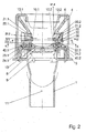
- Fig. 1 forms a pipe socket 1 with a flange 2, a pair of glasses 3, an attachment 4 with a beaded edge 5, and a down into a hollow cylinder 12 expiring insert funnel 6 the nozzle body.
- the goggles 3 receives a flap 10 which can be pivoted about an axis 8 against the force of a hairpin spring 9 and laterally a valve 7, for example a pressure relief valve. They (3) and the attachment 4 are attached to the flange 2.
- the hollow cylinder 12 serves to guide a filling tube, not shown, of a fuel nozzle.
- the filling tube has the diesel fuel standardized diameter, which is larger than that of a filling tube for unleaded gasoline. The latter is still referred to as the "wrong" filling tube.
- the hollow cylinder 12 has the diameter 12.1, which just lets through the "correct" filling tube. Furthermore, the hollow cylinder 12 is surrounded by a flange 12.2, on which the device according to the invention for protection against misfuelling is arranged. The associated tension spring, a hollow spring 12 surrounding the tube spring 14 already belongs to this device. Likewise, one of the two opposite windows 13 in the hollow cylinder 12. The imaginary axis and insertion of a filling tube is denoted by 11. A conductor 15 dissipates electrostatic charges.
- Fig. 2 the parts 20-24 of the protective device are recognizable. Their form and their interaction is only on the basis of the cross sections in the Fig. 3 to 6 clearly, which is discussed below.
- the opposing windows 13.1, 13.2 of the hollow cylinder are sliding guides 20.1, 24.2, in which a first and a second slide 21.1, 21.2 are guided in a plane normal to the axis 11 in the radial direction.
- the slides 21.1, 21.2 and their guides have a rectangular cross-section and inclined contact surfaces 21.3, 21.4, which in their normal position (s. Fig. 7 ) protrude into the hollow cylinder 12.
- the slides 21,1, 21.2 are connected to each other by means of a rigid (or at least stiff) bracket 22, which surrounds the hollow cylinder 12.
- a rigid (or at least stiff) bracket 22 which surrounds the hollow cylinder 12.
- One end of the bracket 22 is pivotally mounted in the first slide 21.1 by means of an axially parallel pin 22.1; the other end is pivotally and slidably mounted by means of a likewise axially parallel pin 22.2 in the second slide.
- This bolt 22.2 cooperates with a rotatable ring 23 arranged under the slides 21.1, 21.2, which in turn cooperates again with likewise radially displaceable latches 24.1, 24.2 lying in an axially normal plane, which latches 24.1, 24.2 lock the flap 10.
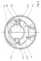
- Fig. 3 is the hollow cylinder 12 with the aligned radial sliding guides 20.1, 20.2 to see in cross section.
- the two slides 21.1 and 21.2 are connected by the rigid bracket 22 together.
- the distance between the pin 22.1 at one end of the bracket 22 and the pin 22.2 at the other end is thus constant.
- the position of the bracket 22 and thus the attached to its ends parts (pin 22.1 and 22.2 bolts) with respect to the slide 21.1,21.2 does not change. This happens when a "wrong" (too small) stuffing tube is inserted.
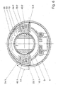
- Fig. 4 It can be seen how the other end of the bracket 22 is mounted pivotably and displaceably in the second slider 21.2 by means of the axially parallel bolt 22.2.
- a first slide 30 is provided in the slider 21.2, in which the bolt 22.2 of the bracket 22 engages.
- the backdrop closes with the radius an angle 31 a.
- the scenery 30 does not have to be straight; she can, as in Fig. 4 follow a curve, whereby the force curve is changed in the desired manner.
- the two slides 21.1, 21.2 are removed from each other.
- the bolt 22.2 of the bracket 22 is displaced by the first link 30 in the circumferential direction.
- the bolt 22.2 protrudes through the gate 30 by down in the rotatable ring 23 (see Fig. 2 ) and twists it around the axis 11.
- Fig. 5 is that to be seen.
- the rotatable ring 23 encloses the hollow cylinder 12, it is effectively mounted on it and is rotated by the bolt 22.2, here in the direction of arrow 35.
- the bolt 22.2 engages in a second link 36, because its distance from the axis 11th when moving the slider 21.1, 21.2 changes.
- the second link 36 is almost radial, because it must allow this shift. Due to the low inclination against the radius kinematic corrections are possible.
- hose spring 14 engages with its one end on the rotatable ring 23 and with the other on the hollow cylinder 12.
- Fig. 6 shows a way to implement the rotation of the ring 23 in an access barrier for a "wrong" filling tube.
- On the underside of the rotatable ring 23 are two pins 23.1, 23.2 (it could also be more), which engage in third scenes 40.1, 40.2 of a first and a second latch 24.1, 24.2.
- the bars are guided on the glasses 3 in alignment with each other in the radial direction. They grip in closed position (see Fig. 8 ) in grooves 10.1, 10.2 on the edge of the flap 10 and lock them.
- the flap is released for regurgitation through the "correct" filling tube.
- the third backdrop runs straight here at an angle 41 to the radius.
- FIG. 7 and 8th correspond to the Fig. 2 and 6 , they show the same, but with the flap 10 locked.
- Fig. 9 and 10 differs from that described above only in the way to implement the rotation of the ring 23 in an access barrier for a "false" filling tube. All other parts do not differ and therefore retain the reference numerals of Figs Fig. 1 only indicated hose spring 14 exerts between the pin 14.2 and the pin 23.3 on the rotatable ring 23 a circumferential force, which seeks to bring the ring 23 in the locked position.
Landscapes
- Engineering & Computer Science (AREA)
- Life Sciences & Earth Sciences (AREA)
- Sustainable Development (AREA)
- Sustainable Energy (AREA)
- Chemical & Material Sciences (AREA)
- Combustion & Propulsion (AREA)
- Transportation (AREA)
- Mechanical Engineering (AREA)
- Cooling, Air Intake And Gas Exhaust, And Fuel Tank Arrangements In Propulsion Units (AREA)
Abstract
Description
- Die Erfindung betrifft den Einfüllstutzen eines Treibstofftanks mit Schutz vor Fehlbetankung, bestehend aus einem Stutzenkörper, mindestens einem durch Einführen des Füllrohres vom richtigen Durchmesser gegen Federkraft verschiebbaren Teil, einem drehbaren Ring und von diesem drehbaren Ring betätigten Schließelementen, wobei zwischen dem verschiebbaren Teil und dem drehbaren Ring eine Übertragungsvorrichtung angeordnet ist.
- Bei Kraftfahrzeugen mit Dieselmotor ist die Gefahr einer Fehlbetankung groß, weil der Durchmesser des Füllrohres einer Zapfpistole für bleifreies Benzin kleiner als der einer Zapfpistole für Dieselkraftstoff ist. Der richtige Durchmesser ist somit der größere und es geht im Folgenden darum, das Einführen eines kleineren Füllrohres in ein größeres Loch ganz sicher zu verhindern.
- Aus der
EP 1 284 212 B1 ist es bekannt, im Einfüllstutzen ein in Längsrichtung verschiebbares Rohrstück mit tankseitig einer Einschnürung vorzusehen, deren Durchmesser kleiner als der eines Füllrohres für Dieselkraftstoff, aber größer als der eines Füllrohres für Benzin ist. Dieses Rohrstück wirkt über eine Kulissenführung auf die Schließelemente, entweder direkt auf verschiebbare Schließelemente oder über ein es umgebendes verdrehbares Rohrstück. - Diese Sicherheitsvorrichtung versagt aber bei schrägem Einführen des Füllrohres beziehungsweise lässt sich durch seitliches Anpressen des Füllrohres überlisten. Wegen der für die beiden Rohrstücke nötigen Führungslänge ist der Raumbedarf eines solchen Einfüllstutzens in Längsrichtung erheblich und ist die Anbringung weiterer Einbauten, wie etwa Ventile und Abzweigungen für entweichende Kraftstoffdämpfe schwierig bis unmöglich.
- Es ist somit die der Erfindung zugrunde liegende Aufgabe, einen absolut sicheren Schutz vor Fehlbetankung zu bieten, bei verringerter Einbaulänge und ungehinderter Anbringung zusätzlicher Ventile oder dergleichen.
- Erfindungsgemäß wird das mit denn kennzeichnenden Merkmalen des unabhängigen Anspruches erreicht. Die beiden gegenüber angeordneten Schieber sind unabhängig voneinander verschiebbar. Wird nur einer verschoben, oder beide nicht ganz, so bleiben die Schließelemente geschlossen. Nur bei Einführen des "richtigen" Füllrohres und somit gleichzeitiger Einwirkung auf die schrägen Anlaufflächen werden beide Schieber gleichzeitig weit genug verschoben und nur dann werden die Schließelemente geöffnet. Diese selektive Wirkung beruht auf dem starren Bügel, der beide Schieber die Einfüllöffnung umgreifend verbindet, und mit einem der Schieber über eine Kulissenführung zusammenwirkt. Diese und eine weitere Kulissenführung zwischen dem Bügel und dem drehbaren Ring bildet die Übertragungsvorrichtung, die die zwangsläufige Verbindung zwischen den Schiebern und den Schließelementen herstellt.
- Dabei bieten die Kulissen den Vorteil, dass durch ihren Verlauf auch ein günstiger Verlauf der Öffnungs- beziehungsweise Schließkräfte erreicht wird. Vorzugsweise verläuft die erste Kulisse bezogen auf die Schieberichtung des zweiten Schiebers schräg und die zweite Kulisse ungefähr in Schieberichtung, also radial (Anspruch 2), und hat der starre Bügel an seinem zweiten Ende einen Bolzen, der mit beiden Kulissen zusammenwirkt (Anspruch 3).
- Die Schließelemente können im Rahmen der Erfindung sehr verschieden gestaltet sein (Ansprüche 4 bis 10). Sie können entweder auf eine (hier fälschlich) so genannte Bleifreiklappe einwirken (Ansprüche 4 bis 6), die ein Einführen des falschen Füllrohres verhindert oder das direkt erreichen, ohne Bleifreiklappe (Anspruch 7). Dabei können die Schließelemente verschiebbare Riegel oder verschwenkbare Teile sein. Sind sie verschwenkbare Teile (mindestens zwei oder in größerer Anzahl in der Art einer Irisblende) so kann dazu eine dritte Kulissenführung vorgesehen sein.
-
- Fig.1:
- Längsschnitt durch einen erfindungsgemäßen Einfüllstutzen,
- Fig 2:
- Längsschnitt nach F-F in
Fig. 1 , - Fig 3:
- Querschnitt nach M-M in
Fig. 2 , - Fig 4:
- Querschnitt nach L-L in
Fig. 2 , - Fig 5:
- Querschnitt nach K-K in
Fig. 2 , - Fig 6:
- Querschnitt nach J-J in
Fig. 2 , - Fig 7:
- wie
Fig. 2 , aber in Sperrstellung, - Fig 8:
- wie
Fig. 6 , aber in Sperrstellung, - Fig 9:
- Explosionsdarstellung einer abgewandelten Ausführungsform,
- Fig10:
- Draufsicht nach X in
Fig. 9 . - In
Fig. 1 bildet ein Rohrstutzen 1 mit einem Flansch 2, eine Brille 3, ein Aufsatz 4 mit einem Bördelrand 5, und ein nach unten in einen Hohlzylinder 12 auslaufender Einsatztrichter 6 den Stutzenkörper. Die Brille 3 nimmt eine um eine Achse 8 gegen die Kraft einer Haarnadelfeder 9 aufschwenkbare Klappe 10 und seitlich ein Ventil 7, zum Beispiel ein Überdruckventil, auf. Sie (3) und der Aufsatz 4 sind am Flansch 2 befestigt. Der Hohlzylinder 12 dient der Führung eines nicht dargestellten Füllrohres einer Zapfpistole. Das Füllrohr hat den für Dieselkraftstoff genormten Durchmesser, der größer als der eines Füllrohres für bleifreies Benzin ist. Letzteres wird weiterhin als "falsches" Füllrohr bezeichnet. Der Hohlzylinder 12 hat den Durchmesser 12.1, der das "richtige" Füllrohr gerade durchlässt. Weiters ist der Hohlzylinder 12 von einem Flansch 12.2 umgeben, an dem die erfindungsgemäße Vorrichtung zum Schutz vor Fehlbetankung angeordnet ist. Die zugehörige Zugfeder, eine den Hohlzylinder 12 umgebende Schlauchfeder 14, gehört bereits zu dieser Vorrichtung. Ebenso eines der beiden einander gegenüberliegenden Fenster 13 im Hohlzylinder 12. Die gedachte Achse und Einführrichtung eines Füllrohres ist mit 11 bezeichnet. Ein Leiter 15 leitet elektrostatische Ladungen ab. - In
Fig. 2 sind die Teile 20-24 der Schutzvorrichtung erkennbar. Ihre Form und ihr Zusammenwirken wird aber erst anhand der Querschnitte in denFig. 3 bis 6 deutlich, auf die weiter unten eingegangen ist. Die einander gegenüberliegenden Fenster 13.1, 13.2 des Hohlzylinders sind Schiebeführungen 20.1, 24.2, in denen ein erster und ein zweiter Schieber 21.1, 21.2 in einer zur Achse 11 normalen Ebene in radialer Richtung geführt sind. Die Schieber 21.1, 21.2 und ihre Führungen haben einen rechteckigen Querschnitt und schräge Anlaufflächen 21.3, 21.4, die in ihrer Grundstellung (s.Fig. 7 ) in den Hohlzylinder 12 hineinragen. - Die Schieber 21,1, 21.2 sind mittels eines starren (oder zumindest steifen) Bügels 22 miteinander verbunden, welcher den Hohlzylinder 12 umgreift. Ein Ende des Bügels 22 ist im ersten Schieber 21.1 mittels eines achsparallelen Stiftes 22.1 schwenkbar gelagert; das andere Ende ist mittels eines ebenfalls achsparallelen Bolzens 22.2 im zweiten Schieber schwenkbar und verschiebbar gelagert. Dieser Bolzen 22.2 wirkt mit einem unter den Schiebern 21.1, 21.2 angeordneten drehbaren Ring 23 zusammen, welcher seinerseits wieder mit ebenfalls in einer achsnormalen Ebene darunter liegenden radial verschiebbaren Riegeln 24.1, 24.2 zusammenwirkt, welche Riegel 24.1, 24.2 die Klappe 10 verriegeln.
- In
Fig. 3 ist der Hohlzylinder 12 mit den miteinander fluchtenden radialen Schiebeführungen 20.1, 20.2 im Querschnitt zu sehen. Die beiden Schieber 21.1 und 21.2 sind durch den starren Bügel 22 miteinander verbunden. Der Abstand zwischen dem Stift 22.1 an einem, Ende des Bügels 22 und dem Bolzen 22.2 am anderen Ende ist somit konstant. Solange beide Schieber gleichsinnig und gleich weit verschoben werden, ändert sich die Lage des Bügels 22 und damit die der an seinen Enden angebrachten Teile (Stift 22.1 und Bolzen 22.2) bezüglich der Schieber 21.1,21.2 nicht. Das tritt ein, wenn ein "falsches" (zu kleines) Füllrohr eingeführt wird. - In
Fig. 4 ist zu sehen, wie das andere Ende des Bügels 22 mittels des achsparallelen Bolzens 22.2 im zweiten Schieber 21.2 schwenkbar und verschiebbar gelagert ist. Dazu ist im Schieber 21.2 eine erste Kulisse 30 vorgesehen, in die der Bolzen 22.2 des Bügels 22 eingreift. Die Kulisse schließt mit dem Radius einen Winkel 31 ein. Die Kulisse 30 muss nicht gerade verlaufen; sie kann, wie inFig. 4 einer Kurve folgen, wodurch der Kraftverlauf in gewünschter Weise verändert wird. Bei Einführen eines Füllrohres mit dem "richtigen" Durchmesser (beinahe 12.1) werden die beiden Schieber 21.1, 21.2 voneinander entfernt. Dabei wird der Bolzen 22.2 des Bügels 22 durch die erste Kulisse 30 in Umfangsrichtung verschoben. Der Bolzen 22.2 ragt durch die Kulisse 30 durch nach unten in den verdrehbaren Ring 23 (sieheFig. 2 ) und verdreht ihn um die Achse 11. - In
Fig. 5 ist das zu sehen. Der verdrehbare Ring 23 umschließt den Hohlzylinder 12, er ist gewissermaßen auf ihm gelagert und wird von dem Bolzen 22.2 verdreht, hier in Richtung des Pfeiles 35. Dazu greift der Bolzen 22.2 in eine zweite Kulisse 36 ein, weil sich seine Entfernung von der Achse 11 bei Bewegung der Schieber 21.1, 21.2 ändert. Die zweite Kulisse 36 verläuft beinahe radial, weil sie diese Verlagerung erlauben muss. Durch die geringe Neigung gegen den Radius sind kinematische Korrekturen möglich. Die inFig. 1 nur angedeutete Schlauchfeder 14 greift mit ihrem einen Ende am verdrehbaren Ring 23 und mit dem anderen am Hohlzylinder 12 an. -
Fig. 6 zeigt einen Weg, die Verdrehung des Ringes 23 in eine Zugangssperre für ein "falsches" Füllrohr umzusetzen. An der Unterseite des verdrehbaren Ringes 23 sind zwei Stifte 23.1, 23.2 (es könnten auch mehrere sein) angeordnet, die in dritte Kulissen 40.1, 40.2 eines ersten und eines zweiten Riegels 24.1, 24.2 eingreifen. Die Riegel sind an der Brille 3 miteinander fluchtend in radialer Richtung geführt. Sie greifen in geschlossener Stellung (sieheFig. 8 ) in Nuten 10.1, 10.2 am Rand der Klappe 10 ein und verriegeln diese. InFig. 6 ist die Klappe zum Aufstoßen durch das "richtige" Füllrohr freigegeben. Die dritte Kulisse verläuft hier geradlinig unter einem Winkel 41 zum Radius.Fig. 7 und8 entsprechen denFig. 2 und6 , sie zeigen dasselbe, jedoch mit verriegelter Klappe 10. - Die Variante der
Fig. 9 und10 unterscheidet sich von der oben Beschrieben nur in dem Weg, die Verdrehung des Ringes 23 in eine Zugangssperre für ein "falsches" Füllrohr umzusetzen. Alle anderen Teile unterscheiden sich nicht und behalten deshalb die Bezugszeichen der Fig. bis 8. Die inFig. 1 nur angedeutete Schlauchfeder 14 übt zwischen dem Stift 14.2 und dem Stift 23.3 am verdrehbaren Ring 23 eine Umfangskraft aus, die den Ring 23 in die gesperrte Stellung zu bringen trachtet. - Die Bezugszeichen anderer Teile sind um 100 erhöht. In der Explosionsdarstellung der
Fig. 9 hat der verdrehbare Ring 123 an seiner Unterseite eine Anzahl von Stiften 123.1, 123.2, 123.i, die in dritte Kulissen 140.1, 140.2, 140.i eingreifen. Diese dritten Kulissen 140.1, 140.2, 140.i sind in um gehäusefeste Achsen 125.1, 125.2, 125.i schwenkbare Teile 124.1, 124.2, 124.i eingefräst. Diese Teile bilden in der dargestellten Anzahl direkt in der Art einer Irisblende wirkende Schließelemente. Sie verriegeln also nicht eine Klappe sondern bilden selbst die Schließelemente.
Claims (8)
- Einfüllstutzen eines Treibstofftanks mit Schutz vor Fehlbetankung, bestehend aus einem Stutzenkörper, mindestens einem durch Einführen des Füllrohres (vom "richtigen" Durchmesser) gegen Federkraft verschiebbaren Teil, einem drehbaren Ring und von diesem Ring betätigten Schließelementen, wobei zwischen dem verschiebbaren Teil und dem drehbaren Ring (23) eine Übertragungsvorrichtung angeordnet ist, dadurch gekennzeichnet, dassa) im Stutzenkörper (1-6; 12) zwei einander in einer achsnormalen Ebene liegende und verschiebbare Teile (21) im Wesentlichen gegenüber angeordnet sind, welche Teile ein erster und ein zweiter Schieber (21.1, 21.2) mit einander zugewandten schrägen Anlaufflächen (21.3, 21.4) sind, die bei Einführen eines Füllrohres mit dem richtigen größeren Durchmesser eine Verschiebung auswärts erfahren,b) die beiden Schieber (21.1, 21.2) mittels eines starren Bügels (22) miteinander verbunden sind, welcher starre Bügel mit seinem ersten Ende (22.1) am ersten Schieber (21.1) drehbar und mit seinem zweiten Ende (22.2) am zweiten Schieber (21.2) verlagerbar angelenkt ist,c) die Übertragungsvorrichtung besteht aus dem starren Bügel (22), einer ersten Kulissenführung (3 0, 22.2) zwischen dem zweiten Schieber (21.2) und dem starren Bügel (22) und einer zweiten Kulissenführung (36, 22.2) zwischen dem starren Bügel (22) und dem drehbaren Ring (23), wobei die Kulissen (30,36) in der achsnormalen Eben verlaufen.
- Einfüllstutzen nach Anspruch 1, dadurch gekennzeichnet, dass die erste Kulisse (30) bezogen auf die Schieberichtung des zweiten Schiebers (21.2) unter einem Winkel (31) und die zweite Kulisse (36) ungefähr in Schieberichtung verlauft.
- Einfüllstutzen nach Anspruch 1, dadurch gekennzeichnet, dass der starre Bügel (22) an seinem zweiten Ende einen Bolzen (22.2) hat, der mit beiden Kulissen (30,36) zusammenwirkt.
- Einfüllstutzen nach Anspruch 1, dadurch gekennzeichnet, dass die vom verdrehbaren Ring (23) betätigten Schließelemente (24.1, 24.2) eine Anzahl (vorzugsweise zwei) mit einer tankinnenwärts der Schieber (21.1, 21.2) angeordneten Klappe (14) zusammenwirkende Riegel sind.
- Einfüllstutzen nach Anspruch 4, dadurch gekennzeichnet, dass die Riegel (24.1, 24.2) in einer achsnormalen Ebene in entgegengesetzter Richtung verschiebbare Teile sind, die mit dem verdrehbaren Ring (23) über dritte Kulissenführungen (40.1,40.2, 23.1,23.2) zusammenwirken.
- Einfüllstutzen nach Anspruch 4, dadurch gekennzeichnet, dass die Riegel in einer achsnormalen Ebene um eine gehäusefeste Achse schwenkbare Teile sind, die mit dem verdrehbaren Ring über dritte Kulissenführungen zusammenwirken.
- Einfüllstutzen nach Anspruch 1, dadurch gekennzeichnet, dass die vom verdrehbaren Ring (123) betätigten Schließelemente (124.i) eine Anzahl in einer achsnormalen Ebene um eine gehäusefeste Achse (125.i) schwenkbare Teile (124.i) sind, die mit dem verdrehbaren Ring (123) über dritte Kulissenführungen (140.i, 123.i) zusammenwirken.
- Einfüllstutzen nach Anspruch 5 oder 6, dadurch gekennzeichnet, dass die dritten Kulissenführungen (44, 23.1) aus einer Kulisse (40.1, 40.2) am Riegel 24.1,24.2) und einem Stift (23.1, 23.2) am verdrehbaren Ring (23) bestehen.
Applications Claiming Priority (1)
| Application Number | Priority Date | Filing Date | Title |
|---|---|---|---|
| AT0019607U AT9945U1 (de) | 2007-03-27 | 2007-03-27 | Einfüllstutzen eines treibstofftanks mit schutz vor fehlbetankung |
Publications (2)
| Publication Number | Publication Date |
|---|---|
| EP1974976A1 true EP1974976A1 (de) | 2008-10-01 |
| EP1974976B1 EP1974976B1 (de) | 2009-12-30 |
Family
ID=39273038
Family Applications (1)
| Application Number | Title | Priority Date | Filing Date |
|---|---|---|---|
| EP20080005725 Not-in-force EP1974976B1 (de) | 2007-03-27 | 2008-03-27 | Einfüllstutzen eines Treibstofftanks mit Schutz vor Fehlbetankung |
Country Status (4)
| Country | Link |
|---|---|
| US (1) | US7661550B2 (de) |
| EP (1) | EP1974976B1 (de) |
| AT (2) | AT9945U1 (de) |
| DE (1) | DE502008000276D1 (de) |
Cited By (4)
| Publication number | Priority date | Publication date | Assignee | Title |
|---|---|---|---|---|
| EP2093090A1 (de) * | 2008-02-21 | 2009-08-26 | Stant Manufacturing Inc. | Hemmvorrichtung für Kraftstoff-Zapfpistole |
| GB2467095A (en) * | 2008-08-02 | 2010-07-21 | Caparo Ap Braking Ltd | A misfuelling prevention device |
| US8944122B2 (en) | 2012-03-08 | 2015-02-03 | Magna Steyr Fuel Systems Gesmbh | Filler neck with blocker device for diesel fuel tank |
| US10000117B2 (en) | 2012-02-17 | 2018-06-19 | Stant Usa Corp. | Filler neck closure assembly |
Families Citing this family (32)
| Publication number | Priority date | Publication date | Assignee | Title |
|---|---|---|---|---|
| DE202005012256U1 (de) * | 2005-07-27 | 2006-12-14 | Reutter Metallwarenfabrik Gmbh | Fehlbetankungsvorrichtung |
| US20090056831A1 (en) * | 2006-03-15 | 2009-03-05 | Inergy Automotive Systems Research (Societe Anonyme) | Fuel dispensing nozzle inhibitor |
| US20080191424A1 (en) * | 2006-11-09 | 2008-08-14 | Bandelin Electronic Gmbh & Co., Kg | Rotary seal |
| EP2134562B1 (de) * | 2007-04-16 | 2015-09-16 | Illinois Tool Works Inc. | Selektives kraftstoffdüsenhemmsystem |
| DE102008049150A1 (de) * | 2008-06-09 | 2009-12-10 | Kt Projektentwicklungs-Gmbh | Einsatzelement für einen zur tankstellenseitigen Befüllung mit Harnstoff geeigneten Behälter |
| CH699193A2 (fr) | 2008-07-22 | 2010-01-29 | Dg Tec Sarl | Bouchon de réservoir pour un vehicule à moteur diesel. |
| DE112009001823T5 (de) * | 2008-08-20 | 2011-06-01 | Illinois Tool Works Inc., Glenview | Fehlbetankungssperre |
| DE202008011199U1 (de) | 2008-08-22 | 2009-10-29 | Magna Steyr Fuel Systems Gmbh | Tankstutzen mit Sperreinrichtung |
| CN102131669B (zh) * | 2008-08-25 | 2013-12-04 | 株式会社利富高 | 防止误加油装置 |
| US20100218849A1 (en) * | 2009-02-27 | 2010-09-02 | Toyoda Gosei Co., Ltd. | Fuel tank opening-closing device |
| EP2502772B1 (de) * | 2009-11-18 | 2014-08-27 | Nifco Inc. | Vorrichtung zur vermeidung von betankungsfehlern |
| US8539993B2 (en) * | 2010-03-31 | 2013-09-24 | Toyoda Gosei Co., Ltd. | Fuel tank opening and closing device |
| JP5406158B2 (ja) * | 2010-10-14 | 2014-02-05 | 豊田合成株式会社 | 燃料タンクの開閉装置 |
| US20140209203A1 (en) * | 2011-05-12 | 2014-07-31 | Technical Chemical Company | Container construction for dispensing into a fuel receptacle |
| US8678049B2 (en) | 2011-06-03 | 2014-03-25 | Curtis Roys | Method and structure for prevention of incorrect fueling operations for diesel-powered vehicles |
| US9133013B2 (en) | 2011-06-03 | 2015-09-15 | Curtis Roys | Method and structure for prevention of incorrect fueling operations |
| JP5370420B2 (ja) | 2011-06-10 | 2013-12-18 | トヨタ自動車株式会社 | 燃料タンクの給油部構造 |
| DE102011117459A1 (de) * | 2011-06-29 | 2013-01-03 | Volkswagen Aktiengesellschaft | Einfüllstutzen für einen Kraftstoffbehälter |
| US9457650B2 (en) * | 2012-08-28 | 2016-10-04 | Ford Global Technologies, Llc | Drain slot for capless fuel filler insert |
| WO2014057141A1 (es) * | 2012-10-09 | 2014-04-17 | Cie Automotive, S.A. | Dispositivo de entrada para la boca de repostaje de vehículos a motor |
| KR101417637B1 (ko) * | 2013-05-08 | 2014-07-08 | 현대자동차주식회사 | 혼유 방지 필러넥 장치 |
| WO2014183121A1 (en) * | 2013-05-10 | 2014-11-13 | Stant Usa Corp. | Fuel-dispensing nozzle inhibitor |
| KR101481272B1 (ko) * | 2013-05-28 | 2015-01-09 | 현대자동차주식회사 | 혼유 방지 필러넥 장치 |
| KR101500136B1 (ko) | 2013-09-06 | 2015-03-06 | 현대자동차주식회사 | 차량의 오주유 방지장치 |
| JP6231843B2 (ja) * | 2013-10-11 | 2017-11-15 | 株式会社アステア | 誤給油防止装置 |
| KR101481343B1 (ko) | 2013-12-10 | 2015-01-09 | 현대자동차주식회사 | 차량의 혼유 방지 시스템 |
| KR101610503B1 (ko) | 2014-09-05 | 2016-04-07 | 현대자동차주식회사 | 연료 캡 일체형 조리개식 연료 도어 구조 |
| US10081241B2 (en) | 2015-12-10 | 2018-09-25 | Curtis Alan Roys | Diesel fuel guard |
| US10640358B2 (en) | 2017-06-21 | 2020-05-05 | Ford Global Technologies, Llc | Capless refill adapter for a fluid refilling system |
| KR102152242B1 (ko) * | 2019-03-14 | 2020-09-04 | 삼보모터스주식회사 | 차량용 오주유 방지 캡리스 연료 주입 장치 |
| US11358466B2 (en) * | 2019-05-31 | 2022-06-14 | Stant Usa Corp. | Capless closure for fuel filler pipe |
| DE202019105565U1 (de) * | 2019-10-09 | 2021-01-21 | Gerdes Gmbh | Tankstutzenverschluss für einen Kraftstofftank |
Citations (4)
| Publication number | Priority date | Publication date | Assignee | Title |
|---|---|---|---|---|
| FR2762807A1 (fr) * | 1997-04-30 | 1998-11-06 | Coutier Moulage Gen Ind | Embout de fermeture pour tubulure de remplissage d'un reservoir de carburant d'un vehicule automobile |
| EP1262355A1 (de) * | 2001-05-30 | 2002-12-04 | Bayerische Motoren Werke Aktiengesellschaft | Kraftfahrzeug-Kraftstofftank mit einem Einfüllstutzen zur Aufnahme einer Zapfpistole für Dieselkraftstoff |
| EP1284212A1 (de) * | 2001-08-11 | 2003-02-19 | Bayerische Motoren Werke Aktiengesellschaft | Kraftfahrzeug-Kraftstofftank mit einem Einfüllstutzen zur Aufnahme einer Zapfpistole für Dieselkraftstoff |
| EP1712398A1 (de) * | 2004-01-19 | 2006-10-18 | ITW-Automotive Products GmbH & Co. KG | Einfüllstutzen für das Einfüllen von Kraftstoff in einen Fahrzeugtank |
Family Cites Families (47)
| Publication number | Priority date | Publication date | Assignee | Title |
|---|---|---|---|---|
| US3126728A (en) * | 1964-03-31 | nehls | ||
| US3730216A (en) * | 1972-04-06 | 1973-05-01 | Ford Motor Co | Fuel tank insert for admitting preselected pump nozzles |
| US5056570A (en) * | 1990-03-26 | 1991-10-15 | Stant Inc. | Capless vehicle refueling system |
| DE4021218A1 (de) * | 1990-07-04 | 1992-01-09 | Blau Kg Kraftfahrzeugtech | Tankfuellstutzen fuer einen treibstofftank |
| DE4305394C1 (de) * | 1993-02-22 | 1994-04-07 | Daimler Benz Ag | Verschluß für einen Einfüllstutzen eines Kraftstofftankes |
| US5381919A (en) * | 1993-10-18 | 1995-01-17 | Stant Manufacturing Inc. | Push-on fuel cap |
| US5524786A (en) * | 1994-12-27 | 1996-06-11 | Ford Motor Company | Body conforming fuel tank cap latch mechanism |
| DE19520971A1 (de) * | 1995-06-08 | 1996-12-12 | Bayerische Motoren Werke Ag | Tankverschluß, insbesondere an einem Kraftfahrzeug |
| EP0970005A4 (de) * | 1997-02-11 | 2000-08-02 | Stant Mfg Co | Dichtung für tankstutzenverschlussanordnung |
| DE19709416C1 (de) * | 1997-03-07 | 1998-04-30 | Daimler Benz Ag | Vorrichtung zum roboterfähigen Betanken eines Fahrzeuges |
| DE69802405T2 (de) * | 1997-07-17 | 2002-05-29 | Tesma Int Inc | Deckelloses betankungssystem |
| EP0893294B1 (de) * | 1997-07-24 | 2007-01-03 | Nippon Pillar Packing Co., Ltd. | Dichtung für einen Kraftstoffeinfüllstutzen |
| AT408970B (de) * | 1997-11-27 | 2002-04-25 | Blau Internat Gesmbh | Vorrichtung zum verhindern des überfüllens eines kraftstofftankes |
| US6705481B2 (en) * | 1998-03-20 | 2004-03-16 | Temtec Fahrzeutechnick | Actuatable fuel tank closure having guide pipe |
| US6230739B1 (en) * | 1998-05-07 | 2001-05-15 | Tesma International Inc. | Fuel refilling assembly |
| ES2207870T3 (es) * | 1998-12-29 | 2004-06-01 | Mecrom Ott U. Holey Ohg | Tapon de deposito de cierre automatico. |
| ATE248724T1 (de) * | 1999-03-12 | 2003-09-15 | Tesma Motoren Getriebetechnik | Einfüllstutzen für den treibstofftank eines kraftfahrzeuges |
| US6155316A (en) * | 1999-06-30 | 2000-12-05 | Eaton Corporation | Capless fuel tank filler assembly |
| EP1086842B1 (de) * | 1999-09-22 | 2006-03-08 | Toyoda Gosei Co., Ltd. | Betankungsvorrichtung |
| DE10054663B4 (de) * | 1999-11-04 | 2008-01-10 | Alfmeier Präzision AG | Kraftstoffeinfüllstutzen für den Kraftstoffbehälter eines Kraftfahrzeuges |
| WO2002026515A1 (fr) * | 2000-09-27 | 2002-04-04 | Toyoda Gosei Co., Ltd. | Dispositif d'alimentation en huile d'un reservoir a carburant |
| FR2827818B1 (fr) * | 2001-07-25 | 2003-10-24 | Inergy Automotive Systems Man | Systeme d'obturation pour tubulure de remplissage de reservoir a carburant et procede pour ouvrir cette tubulure |
| US20030056837A1 (en) * | 2001-09-26 | 2003-03-27 | Eaton Corporation | Controlling fuel tank vapor venting during refueling |
| US6539990B1 (en) * | 2001-11-20 | 2003-04-01 | Illinois Tool Works Inc. | Capless refueling assembly |
| US6691750B1 (en) * | 2002-11-04 | 2004-02-17 | Stant Manufacturing Inc. | Floating nozzle collar for capless filler neck |
| DE10307355B4 (de) * | 2003-02-21 | 2006-02-09 | Itw Automotive Products Gmbh & Co. Kg | Verschlußvorrichtung für ein Einfüllrohr eines Automobiltanks |
| DE10336776B4 (de) * | 2003-08-08 | 2010-04-08 | Alfmeier Präzision Aktiengesellschaft Baugruppen und Systemlösungen | Einfüllstutzen für den Kraftstoffbehälter eines Kraftfahrzeuges mit einem automatischen Tankverschluss |
| US6923224B1 (en) * | 2004-01-15 | 2005-08-02 | Stant Manufacturing Inc. | Closure and vent system for capless filler neck |
| DE102004011753B3 (de) * | 2004-03-09 | 2005-09-29 | Tesma Europa Gmbh | Tankverschluss |
| US6880594B1 (en) * | 2004-03-19 | 2005-04-19 | Eaton Corporation | Method and arrangement for sealing a capless fuel tank filler tube |
| FR2868738B1 (fr) * | 2004-04-08 | 2006-07-14 | Itw De France Soc Par Actions | Embout pour tubulure de remplissage en carburant d'un vehicule |
| US6945290B1 (en) * | 2004-06-10 | 2005-09-20 | Eaton Corporation | Check valve for use in filler tube vapor recirculation system and method of making same |
| AT7933U1 (de) * | 2004-07-16 | 2005-11-15 | Tesma Motoren Getriebetechnik | Füllrohr für den treibstofftank eines kraftfahrzeuges mit selektiver öffnung |
| US7077178B2 (en) * | 2004-08-11 | 2006-07-18 | Stant Manufacturing Inc. | Fuel-dispensing nozzle inhibitor |
| US7302977B2 (en) * | 2004-09-30 | 2007-12-04 | Stant Manufacturing Inc. | Fuel-dispensing nozzle inhibitor |
| US6968874B1 (en) * | 2004-10-07 | 2005-11-29 | Martinrea Industries, Inc. | Capless automotive fueling system |
| CA2591765C (en) * | 2004-12-20 | 2013-06-11 | Tesma Motoren-Und Getriebetechnik Gmbh | Cap-free filler neck for a motor vehicle tank |
| US7163037B2 (en) * | 2005-01-21 | 2007-01-16 | Eaton Corporation | Guiding movement of capless filler neck closure |
| US7165583B1 (en) * | 2005-01-31 | 2007-01-23 | Eaton Corporation | Door latch for capless filler neck |
| US7665493B2 (en) * | 2005-02-10 | 2010-02-23 | Stant Manufacturing Inc. | Fuel-dispensing nozzle inhibitor |
| US7293586B2 (en) * | 2005-06-22 | 2007-11-13 | Stant Manufacturing Inc. | Fuel-dispensing nozzle inhibitor |
| FR2887498B1 (fr) * | 2005-06-28 | 2008-09-05 | I T W De France Soc Par Action | Tete pour tubulure de remplissage en carburant d'un vehicule |
| US7882862B2 (en) * | 2005-06-30 | 2011-02-08 | Stant Usa Corp. | Fuel and vapor vent management system for filler neck |
| JP2007153049A (ja) * | 2005-12-02 | 2007-06-21 | Toyoda Gosei Co Ltd | タンク用開閉装置 |
| DE102006014438B4 (de) * | 2006-03-27 | 2009-12-24 | Alfmeier Präzision AG Baugruppen und Systemlösungen | Tankeinfüllstutzen für Diesel-Kraftfahrzeuge |
| AT9752U1 (de) * | 2006-12-11 | 2008-03-15 | Magna Steyr Fuel Systems Gesmb | Tankstutzen mit unterdruck-überdruck-ventil |
| US20080178962A1 (en) * | 2007-01-22 | 2008-07-31 | Inergy Auto. Systems Research (Societe Anonyme) | Sealing system for fill pipe head and associated pipe |
-
2007
- 2007-03-27 AT AT0019607U patent/AT9945U1/de not_active IP Right Cessation
-
2008
- 2008-03-27 US US12/056,318 patent/US7661550B2/en not_active Expired - Fee Related
- 2008-03-27 EP EP20080005725 patent/EP1974976B1/de not_active Not-in-force
- 2008-03-27 AT AT08005725T patent/ATE453531T1/de active
- 2008-03-27 DE DE200850000276 patent/DE502008000276D1/de active Active
Patent Citations (5)
| Publication number | Priority date | Publication date | Assignee | Title |
|---|---|---|---|---|
| FR2762807A1 (fr) * | 1997-04-30 | 1998-11-06 | Coutier Moulage Gen Ind | Embout de fermeture pour tubulure de remplissage d'un reservoir de carburant d'un vehicule automobile |
| EP1262355A1 (de) * | 2001-05-30 | 2002-12-04 | Bayerische Motoren Werke Aktiengesellschaft | Kraftfahrzeug-Kraftstofftank mit einem Einfüllstutzen zur Aufnahme einer Zapfpistole für Dieselkraftstoff |
| EP1284212A1 (de) * | 2001-08-11 | 2003-02-19 | Bayerische Motoren Werke Aktiengesellschaft | Kraftfahrzeug-Kraftstofftank mit einem Einfüllstutzen zur Aufnahme einer Zapfpistole für Dieselkraftstoff |
| EP1284212B1 (de) | 2001-08-11 | 2003-12-17 | Bayerische Motoren Werke Aktiengesellschaft | Kraftfahrzeug-Kraftstofftank mit einem Einfüllstutzen zur Aufnahme einer Zapfpistole für Dieselkraftstoff |
| EP1712398A1 (de) * | 2004-01-19 | 2006-10-18 | ITW-Automotive Products GmbH & Co. KG | Einfüllstutzen für das Einfüllen von Kraftstoff in einen Fahrzeugtank |
Cited By (6)
| Publication number | Priority date | Publication date | Assignee | Title |
|---|---|---|---|---|
| EP2093090A1 (de) * | 2008-02-21 | 2009-08-26 | Stant Manufacturing Inc. | Hemmvorrichtung für Kraftstoff-Zapfpistole |
| US7967042B2 (en) | 2008-02-21 | 2011-06-28 | Stant Usa Corp. | Fuel-dispensing nozzle inhibitor |
| GB2467095A (en) * | 2008-08-02 | 2010-07-21 | Caparo Ap Braking Ltd | A misfuelling prevention device |
| GB2467095B (en) * | 2008-08-02 | 2011-01-12 | Caparo Ap Braking Ltd | Misfuelling prevention device |
| US10000117B2 (en) | 2012-02-17 | 2018-06-19 | Stant Usa Corp. | Filler neck closure assembly |
| US8944122B2 (en) | 2012-03-08 | 2015-02-03 | Magna Steyr Fuel Systems Gesmbh | Filler neck with blocker device for diesel fuel tank |
Also Published As
| Publication number | Publication date |
|---|---|
| US20080237231A1 (en) | 2008-10-02 |
| US7661550B2 (en) | 2010-02-16 |
| EP1974976B1 (de) | 2009-12-30 |
| AT9945U1 (de) | 2008-06-15 |
| DE502008000276D1 (de) | 2010-02-11 |
| ATE453531T1 (de) | 2010-01-15 |
Similar Documents
| Publication | Publication Date | Title |
|---|---|---|
| EP1974976B1 (de) | Einfüllstutzen eines Treibstofftanks mit Schutz vor Fehlbetankung | |
| EP0823649B1 (de) | Steckerteil für eine optische Steckverbindung | |
| EP1778512B1 (de) | Füllrohr für den treibstofftank eines kraftfahrzeuges mit selektiver öffnung | |
| EP0599784B1 (de) | Buchsenteil für eine Lichtwellenleiter-Steckverbindung | |
| EP1284212B1 (de) | Kraftfahrzeug-Kraftstofftank mit einem Einfüllstutzen zur Aufnahme einer Zapfpistole für Dieselkraftstoff | |
| DE102006014438B4 (de) | Tankeinfüllstutzen für Diesel-Kraftfahrzeuge | |
| DE60006993T2 (de) | Tankverschlussdeckel für kraftfahrzeug | |
| AT504656B1 (de) | Federscharnier für eine brille | |
| DE102011011518B4 (de) | Füllstutzen für den Treibstofftank eines Kraftfahrzeuges mit selektiver Öffnung | |
| EP0570652A2 (de) | Steckverbindung für Lichtwellenleiter | |
| DE202014101515U1 (de) | Klappfahrradspezifische zweifache Schnelllöseeinheit | |
| DE2817922A1 (de) | Abdichtungsvorrichtung | |
| DE60217790T2 (de) | Türschloss, insbesondere für Haushaltsgeräte | |
| WO2008025587A1 (de) | Tierfalle | |
| EP2892608B1 (de) | Katheterkupplung | |
| DE60030559T2 (de) | Schieberventil für halbleiterbehandlungsvorrichtung | |
| EP0901909A2 (de) | Klammer für Papierbögen | |
| DE102005047459A1 (de) | Tankeinfüllstutzen für ein Diesel-Kraftfahrzeug | |
| DE10151464A1 (de) | Anordnung mit einer Backe, einem Bügelkopfstück und einem Gelenk für eine Brille | |
| DE10054663B4 (de) | Kraftstoffeinfüllstutzen für den Kraftstoffbehälter eines Kraftfahrzeuges | |
| DE102006011198A1 (de) | Verriegelungsvorrichtung | |
| EP1253676B1 (de) | Elektrischer Steckverbinder | |
| DE102012013824A1 (de) | Einfüllstutzen für das Einfüllen von Kraftstoff in einem Fahrzeugtank eines Automobils | |
| EP1072918A2 (de) | Steckerteil für eine optische Steckverbindung | |
| DE102012022394A1 (de) | Kraftstoffeinfülleinrichtung |
Legal Events
| Date | Code | Title | Description |
|---|---|---|---|
| PUAI | Public reference made under article 153(3) epc to a published international application that has entered the european phase |
Free format text: ORIGINAL CODE: 0009012 |
|
| AK | Designated contracting states |
Kind code of ref document: A1 Designated state(s): AT BE BG CH CY CZ DE DK EE ES FI FR GB GR HR HU IE IS IT LI LT LU LV MC MT NL NO PL PT RO SE SI SK TR |
|
| AX | Request for extension of the european patent |
Extension state: AL BA MK RS |
|
| AKX | Designation fees paid | ||
| 17P | Request for examination filed |
Effective date: 20090401 |
|
| RBV | Designated contracting states (corrected) |
Designated state(s): AT BE BG CH CY CZ DE DK EE ES FI FR GB GR HR HU IE IS IT LI LT LU LV MC MT NL NO PL PT RO SE SI SK TR |
|
| GRAP | Despatch of communication of intention to grant a patent |
Free format text: ORIGINAL CODE: EPIDOSNIGR1 |
|
| REG | Reference to a national code |
Ref country code: DE Ref legal event code: 8566 |
|
| GRAS | Grant fee paid |
Free format text: ORIGINAL CODE: EPIDOSNIGR3 |
|
| GRAA | (expected) grant |
Free format text: ORIGINAL CODE: 0009210 |
|
| AK | Designated contracting states |
Kind code of ref document: B1 Designated state(s): AT BE BG CH CY CZ DE DK EE ES FI FR GB GR HR HU IE IS IT LI LT LU LV MC MT NL NO PL PT RO SE SI SK TR |
|
| REG | Reference to a national code |
Ref country code: GB Ref legal event code: FG4D Free format text: NOT ENGLISH |
|
| REG | Reference to a national code |
Ref country code: CH Ref legal event code: EP |
|
| REG | Reference to a national code |
Ref country code: IE Ref legal event code: FG4D |
|
| REF | Corresponds to: |
Ref document number: 502008000276 Country of ref document: DE Date of ref document: 20100211 Kind code of ref document: P |
|
| PG25 | Lapsed in a contracting state [announced via postgrant information from national office to epo] |
Ref country code: NO Free format text: LAPSE BECAUSE OF FAILURE TO SUBMIT A TRANSLATION OF THE DESCRIPTION OR TO PAY THE FEE WITHIN THE PRESCRIBED TIME-LIMIT Effective date: 20100330 Ref country code: LT Free format text: LAPSE BECAUSE OF FAILURE TO SUBMIT A TRANSLATION OF THE DESCRIPTION OR TO PAY THE FEE WITHIN THE PRESCRIBED TIME-LIMIT Effective date: 20091230 Ref country code: FI Free format text: LAPSE BECAUSE OF FAILURE TO SUBMIT A TRANSLATION OF THE DESCRIPTION OR TO PAY THE FEE WITHIN THE PRESCRIBED TIME-LIMIT Effective date: 20091230 Ref country code: SE Free format text: LAPSE BECAUSE OF FAILURE TO SUBMIT A TRANSLATION OF THE DESCRIPTION OR TO PAY THE FEE WITHIN THE PRESCRIBED TIME-LIMIT Effective date: 20091230 |
|
| REG | Reference to a national code |
Ref country code: NL Ref legal event code: VDEP Effective date: 20091230 |
|
| LTIE | Lt: invalidation of european patent or patent extension |
Effective date: 20091230 |
|
| PG25 | Lapsed in a contracting state [announced via postgrant information from national office to epo] |
Ref country code: PL Free format text: LAPSE BECAUSE OF FAILURE TO SUBMIT A TRANSLATION OF THE DESCRIPTION OR TO PAY THE FEE WITHIN THE PRESCRIBED TIME-LIMIT Effective date: 20091230 Ref country code: SI Free format text: LAPSE BECAUSE OF FAILURE TO SUBMIT A TRANSLATION OF THE DESCRIPTION OR TO PAY THE FEE WITHIN THE PRESCRIBED TIME-LIMIT Effective date: 20091230 Ref country code: LV Free format text: LAPSE BECAUSE OF FAILURE TO SUBMIT A TRANSLATION OF THE DESCRIPTION OR TO PAY THE FEE WITHIN THE PRESCRIBED TIME-LIMIT Effective date: 20091230 Ref country code: HR Free format text: LAPSE BECAUSE OF FAILURE TO SUBMIT A TRANSLATION OF THE DESCRIPTION OR TO PAY THE FEE WITHIN THE PRESCRIBED TIME-LIMIT Effective date: 20091230 |
|
| REG | Reference to a national code |
Ref country code: IE Ref legal event code: FD4D |
|
| PG25 | Lapsed in a contracting state [announced via postgrant information from national office to epo] |
Ref country code: IS Free format text: LAPSE BECAUSE OF FAILURE TO SUBMIT A TRANSLATION OF THE DESCRIPTION OR TO PAY THE FEE WITHIN THE PRESCRIBED TIME-LIMIT Effective date: 20100430 Ref country code: BG Free format text: LAPSE BECAUSE OF FAILURE TO SUBMIT A TRANSLATION OF THE DESCRIPTION OR TO PAY THE FEE WITHIN THE PRESCRIBED TIME-LIMIT Effective date: 20100330 Ref country code: EE Free format text: LAPSE BECAUSE OF FAILURE TO SUBMIT A TRANSLATION OF THE DESCRIPTION OR TO PAY THE FEE WITHIN THE PRESCRIBED TIME-LIMIT Effective date: 20091230 Ref country code: ES Free format text: LAPSE BECAUSE OF FAILURE TO SUBMIT A TRANSLATION OF THE DESCRIPTION OR TO PAY THE FEE WITHIN THE PRESCRIBED TIME-LIMIT Effective date: 20100410 Ref country code: NL Free format text: LAPSE BECAUSE OF FAILURE TO SUBMIT A TRANSLATION OF THE DESCRIPTION OR TO PAY THE FEE WITHIN THE PRESCRIBED TIME-LIMIT Effective date: 20091230 Ref country code: RO Free format text: LAPSE BECAUSE OF FAILURE TO SUBMIT A TRANSLATION OF THE DESCRIPTION OR TO PAY THE FEE WITHIN THE PRESCRIBED TIME-LIMIT Effective date: 20091230 |
|
| PG25 | Lapsed in a contracting state [announced via postgrant information from national office to epo] |
Ref country code: CZ Free format text: LAPSE BECAUSE OF FAILURE TO SUBMIT A TRANSLATION OF THE DESCRIPTION OR TO PAY THE FEE WITHIN THE PRESCRIBED TIME-LIMIT Effective date: 20091230 Ref country code: SK Free format text: LAPSE BECAUSE OF FAILURE TO SUBMIT A TRANSLATION OF THE DESCRIPTION OR TO PAY THE FEE WITHIN THE PRESCRIBED TIME-LIMIT Effective date: 20091230 |
|
| BERE | Be: lapsed |
Owner name: MAGNA STEYR FUEL SYSTEMS GESMBH Effective date: 20100331 |
|
| PG25 | Lapsed in a contracting state [announced via postgrant information from national office to epo] |
Ref country code: GR Free format text: LAPSE BECAUSE OF FAILURE TO SUBMIT A TRANSLATION OF THE DESCRIPTION OR TO PAY THE FEE WITHIN THE PRESCRIBED TIME-LIMIT Effective date: 20100331 Ref country code: CY Free format text: LAPSE BECAUSE OF FAILURE TO SUBMIT A TRANSLATION OF THE DESCRIPTION OR TO PAY THE FEE WITHIN THE PRESCRIBED TIME-LIMIT Effective date: 20091230 Ref country code: MC Free format text: LAPSE BECAUSE OF NON-PAYMENT OF DUE FEES Effective date: 20100331 Ref country code: IE Free format text: LAPSE BECAUSE OF FAILURE TO SUBMIT A TRANSLATION OF THE DESCRIPTION OR TO PAY THE FEE WITHIN THE PRESCRIBED TIME-LIMIT Effective date: 20091230 |
|
| PLBE | No opposition filed within time limit |
Free format text: ORIGINAL CODE: 0009261 |
|
| STAA | Information on the status of an ep patent application or granted ep patent |
Free format text: STATUS: NO OPPOSITION FILED WITHIN TIME LIMIT |
|
| 26N | No opposition filed |
Effective date: 20101001 |
|
| REG | Reference to a national code |
Ref country code: FR Ref legal event code: ST Effective date: 20101130 |
|
| PG25 | Lapsed in a contracting state [announced via postgrant information from national office to epo] |
Ref country code: FR Free format text: LAPSE BECAUSE OF NON-PAYMENT OF DUE FEES Effective date: 20100331 Ref country code: DK Free format text: LAPSE BECAUSE OF FAILURE TO SUBMIT A TRANSLATION OF THE DESCRIPTION OR TO PAY THE FEE WITHIN THE PRESCRIBED TIME-LIMIT Effective date: 20091230 |
|
| PG25 | Lapsed in a contracting state [announced via postgrant information from national office to epo] |
Ref country code: BE Free format text: LAPSE BECAUSE OF NON-PAYMENT OF DUE FEES Effective date: 20100331 |
|
| PG25 | Lapsed in a contracting state [announced via postgrant information from national office to epo] |
Ref country code: IT Free format text: LAPSE BECAUSE OF FAILURE TO SUBMIT A TRANSLATION OF THE DESCRIPTION OR TO PAY THE FEE WITHIN THE PRESCRIBED TIME-LIMIT Effective date: 20091230 |
|
| PG25 | Lapsed in a contracting state [announced via postgrant information from national office to epo] |
Ref country code: MT Free format text: LAPSE BECAUSE OF FAILURE TO SUBMIT A TRANSLATION OF THE DESCRIPTION OR TO PAY THE FEE WITHIN THE PRESCRIBED TIME-LIMIT Effective date: 20091230 |
|
| PG25 | Lapsed in a contracting state [announced via postgrant information from national office to epo] |
Ref country code: LU Free format text: LAPSE BECAUSE OF NON-PAYMENT OF DUE FEES Effective date: 20100327 Ref country code: PT Free format text: LAPSE BECAUSE OF FAILURE TO SUBMIT A TRANSLATION OF THE DESCRIPTION OR TO PAY THE FEE WITHIN THE PRESCRIBED TIME-LIMIT Effective date: 20100530 Ref country code: HU Free format text: LAPSE BECAUSE OF FAILURE TO SUBMIT A TRANSLATION OF THE DESCRIPTION OR TO PAY THE FEE WITHIN THE PRESCRIBED TIME-LIMIT Effective date: 20100701 |
|
| PG25 | Lapsed in a contracting state [announced via postgrant information from national office to epo] |
Ref country code: TR Free format text: LAPSE BECAUSE OF FAILURE TO SUBMIT A TRANSLATION OF THE DESCRIPTION OR TO PAY THE FEE WITHIN THE PRESCRIBED TIME-LIMIT Effective date: 20091230 |
|
| REG | Reference to a national code |
Ref country code: CH Ref legal event code: PL |
|
| GBPC | Gb: european patent ceased through non-payment of renewal fee |
Effective date: 20120327 |
|
| PG25 | Lapsed in a contracting state [announced via postgrant information from national office to epo] |
Ref country code: GB Free format text: LAPSE BECAUSE OF NON-PAYMENT OF DUE FEES Effective date: 20120327 Ref country code: LI Free format text: LAPSE BECAUSE OF NON-PAYMENT OF DUE FEES Effective date: 20120331 Ref country code: CH Free format text: LAPSE BECAUSE OF NON-PAYMENT OF DUE FEES Effective date: 20120331 |
|
| PGFP | Annual fee paid to national office [announced via postgrant information from national office to epo] |
Ref country code: AT Payment date: 20180322 Year of fee payment: 11 |
|
| REG | Reference to a national code |
Ref country code: AT Ref legal event code: MM01 Ref document number: 453531 Country of ref document: AT Kind code of ref document: T Effective date: 20190327 |
|
| PG25 | Lapsed in a contracting state [announced via postgrant information from national office to epo] |
Ref country code: AT Free format text: LAPSE BECAUSE OF NON-PAYMENT OF DUE FEES Effective date: 20190327 |
|
| PGFP | Annual fee paid to national office [announced via postgrant information from national office to epo] |
Ref country code: DE Payment date: 20200320 Year of fee payment: 13 |
|
| REG | Reference to a national code |
Ref country code: DE Ref legal event code: R119 Ref document number: 502008000276 Country of ref document: DE |
|
| PG25 | Lapsed in a contracting state [announced via postgrant information from national office to epo] |
Ref country code: DE Free format text: LAPSE BECAUSE OF NON-PAYMENT OF DUE FEES Effective date: 20211001 |