EP1974976A1 - Fill supports for a fuel tank guarding against incorrect fuelling - Google Patents
Fill supports for a fuel tank guarding against incorrect fuelling Download PDFInfo
- Publication number
- EP1974976A1 EP1974976A1 EP20080005725 EP08005725A EP1974976A1 EP 1974976 A1 EP1974976 A1 EP 1974976A1 EP 20080005725 EP20080005725 EP 20080005725 EP 08005725 A EP08005725 A EP 08005725A EP 1974976 A1 EP1974976 A1 EP 1974976A1
- Authority
- EP
- European Patent Office
- Prior art keywords
- rotatable ring
- filler neck
- slider
- neck according
- rigid bracket
- Prior art date
- Legal status (The legal status is an assumption and is not a legal conclusion. Google has not performed a legal analysis and makes no representation as to the accuracy of the status listed.)
- Granted
Links
Images


Classifications
-
- B—PERFORMING OPERATIONS; TRANSPORTING
- B60—VEHICLES IN GENERAL
- B60K—ARRANGEMENT OR MOUNTING OF PROPULSION UNITS OR OF TRANSMISSIONS IN VEHICLES; ARRANGEMENT OR MOUNTING OF PLURAL DIVERSE PRIME-MOVERS IN VEHICLES; AUXILIARY DRIVES FOR VEHICLES; INSTRUMENTATION OR DASHBOARDS FOR VEHICLES; ARRANGEMENTS IN CONNECTION WITH COOLING, AIR INTAKE, GAS EXHAUST OR FUEL SUPPLY OF PROPULSION UNITS IN VEHICLES
- B60K15/00—Arrangement in connection with fuel supply of combustion engines or other fuel consuming energy converters, e.g. fuel cells; Mounting or construction of fuel tanks
- B60K15/03—Fuel tanks
- B60K15/04—Tank inlets
- B60K2015/0458—Details of the tank inlet
- B60K2015/0483—Means to inhibit the introduction of too small or too big filler nozzles
-
- Y—GENERAL TAGGING OF NEW TECHNOLOGICAL DEVELOPMENTS; GENERAL TAGGING OF CROSS-SECTIONAL TECHNOLOGIES SPANNING OVER SEVERAL SECTIONS OF THE IPC; TECHNICAL SUBJECTS COVERED BY FORMER USPC CROSS-REFERENCE ART COLLECTIONS [XRACs] AND DIGESTS
- Y10—TECHNICAL SUBJECTS COVERED BY FORMER USPC
- Y10T—TECHNICAL SUBJECTS COVERED BY FORMER US CLASSIFICATION
- Y10T137/00—Fluid handling
- Y10T137/8593—Systems
- Y10T137/86292—System with plural openings, one a gas vent or access opening
- Y10T137/86324—Tank with gas vent and inlet or outlet
- Y10T137/86332—Vent and inlet or outlet in unitary mounting
Abstract
Description
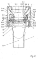
Die Erfindung betrifft den Einfüllstutzen eines Treibstofftanks mit Schutz vor Fehlbetankung, bestehend aus einem Stutzenkörper, mindestens einem durch Einführen des Füllrohres vom richtigen Durchmesser gegen Federkraft verschiebbaren Teil, einem drehbaren Ring und von diesem drehbaren Ring betätigten Schließelementen, wobei zwischen dem verschiebbaren Teil und dem drehbaren Ring eine Übertragungsvorrichtung angeordnet ist.The invention relates to the filler neck of a fuel tank with protection against misfuelling, consisting of a nozzle body, at least one displaceable by inserting the filling tube of the correct diameter against spring force part, a rotatable ring and actuated by this rotatable ring closure elements, wherein between the displaceable part and the rotatable Ring a transmission device is arranged.
Bei Kraftfahrzeugen mit Dieselmotor ist die Gefahr einer Fehlbetankung groß, weil der Durchmesser des Füllrohres einer Zapfpistole für bleifreies Benzin kleiner als der einer Zapfpistole für Dieselkraftstoff ist. Der richtige Durchmesser ist somit der größere und es geht im Folgenden darum, das Einführen eines kleineren Füllrohres in ein größeres Loch ganz sicher zu verhindern.In diesel vehicles, the risk of misfuelling is great, because the diameter of the filling tube of a fuel nozzle for unleaded gasoline is smaller than that of a fuel nozzle for diesel fuel. The correct diameter is therefore the larger and it is about to prevent the introduction of a smaller filling tube into a larger hole quite sure.
Aus der
Diese Sicherheitsvorrichtung versagt aber bei schrägem Einführen des Füllrohres beziehungsweise lässt sich durch seitliches Anpressen des Füllrohres überlisten. Wegen der für die beiden Rohrstücke nötigen Führungslänge ist der Raumbedarf eines solchen Einfüllstutzens in Längsrichtung erheblich und ist die Anbringung weiterer Einbauten, wie etwa Ventile und Abzweigungen für entweichende Kraftstoffdämpfe schwierig bis unmöglich.However, this safety device fails with oblique insertion of the filling tube or can be tricked by lateral pressing of the filling tube. Because of the need for the two pieces of pipe guide length of the space requirement of such a filler neck in the longitudinal direction is considerable and the attachment of other fittings, such as valves and branches for escaping fuel vapors difficult to impossible.
Es ist somit die der Erfindung zugrunde liegende Aufgabe, einen absolut sicheren Schutz vor Fehlbetankung zu bieten, bei verringerter Einbaulänge und ungehinderter Anbringung zusätzlicher Ventile oder dergleichen.It is therefore the object underlying the invention to provide absolutely safe protection against misfuelling, with reduced installation length and unhindered attachment of additional valves or the like.
Erfindungsgemäß wird das mit denn kennzeichnenden Merkmalen des unabhängigen Anspruches erreicht. Die beiden gegenüber angeordneten Schieber sind unabhängig voneinander verschiebbar. Wird nur einer verschoben, oder beide nicht ganz, so bleiben die Schließelemente geschlossen. Nur bei Einführen des "richtigen" Füllrohres und somit gleichzeitiger Einwirkung auf die schrägen Anlaufflächen werden beide Schieber gleichzeitig weit genug verschoben und nur dann werden die Schließelemente geöffnet. Diese selektive Wirkung beruht auf dem starren Bügel, der beide Schieber die Einfüllöffnung umgreifend verbindet, und mit einem der Schieber über eine Kulissenführung zusammenwirkt. Diese und eine weitere Kulissenführung zwischen dem Bügel und dem drehbaren Ring bildet die Übertragungsvorrichtung, die die zwangsläufige Verbindung zwischen den Schiebern und den Schließelementen herstellt.According to the invention is achieved with because characterizing features of the independent claim. The two oppositely arranged slides are independently displaceable. If only one is moved, or both are not completely, then the closing elements remain closed. Only with the introduction of the "correct" filling tube and thus simultaneous action on the inclined contact surfaces both slides are simultaneously moved far enough and only then the closing elements are opened. This selective effect is based on the rigid bracket, which connects both slide the filling opening encompassing, and cooperates with one of the slide via a slotted guide. This and another sliding guide between the bracket and the rotatable ring forms the transmission device, which establishes the positive connection between the slides and the closing elements.
Dabei bieten die Kulissen den Vorteil, dass durch ihren Verlauf auch ein günstiger Verlauf der Öffnungs- beziehungsweise Schließkräfte erreicht wird. Vorzugsweise verläuft die erste Kulisse bezogen auf die Schieberichtung des zweiten Schiebers schräg und die zweite Kulisse ungefähr in Schieberichtung, also radial (Anspruch 2), und hat der starre Bügel an seinem zweiten Ende einen Bolzen, der mit beiden Kulissen zusammenwirkt (Anspruch 3).The scenes offer the advantage that their course also a favorable course of the opening or closing forces is achieved. Preferably, the first link extends obliquely relative to the sliding direction of the second slider and the second link approximately in the sliding direction, ie radially (claim 2), and the rigid bracket at its second end a bolt which cooperates with two scenes (claim 3).
Die Schließelemente können im Rahmen der Erfindung sehr verschieden gestaltet sein (Ansprüche 4 bis 10). Sie können entweder auf eine (hier fälschlich) so genannte Bleifreiklappe einwirken (Ansprüche 4 bis 6), die ein Einführen des falschen Füllrohres verhindert oder das direkt erreichen, ohne Bleifreiklappe (Anspruch 7). Dabei können die Schließelemente verschiebbare Riegel oder verschwenkbare Teile sein. Sind sie verschwenkbare Teile (mindestens zwei oder in größerer Anzahl in der Art einer Irisblende) so kann dazu eine dritte Kulissenführung vorgesehen sein.The closing elements can be designed very differently within the scope of the invention (claims 4 to 10). You can either on a (here falsely) so-called lead free flap act (
- Fig.1:Fig.1:
- Längsschnitt durch einen erfindungsgemäßen Einfüllstutzen,Longitudinal section through a filler neck according to the invention,
- Fig 2:Fig. 2:
-
Längsschnitt nach F-F in
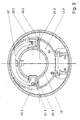
Fig. 1 ,Longitudinal section to FF inFig. 1 . - Fig 3:Fig. 3:
-
Querschnitt nach M-M in
Fig. 2 ,Cross section after MM inFig. 2 . - Fig 4:Fig. 4:
-
Querschnitt nach L-L in
Fig. 2 ,Cross section after LL inFig. 2 . - Fig 5:Fig. 5:
-
Querschnitt nach K-K in
Fig. 2 ,Cross section to KK inFig. 2 . - Fig 6:Fig. 6:
-
Querschnitt nach J-J in
Fig. 2 ,Cross-section after JJ inFig. 2 . - Fig 7:Fig. 7:
-
wie
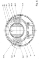
Fig. 2 , aber in Sperrstellung,asFig. 2 but in locked position, - Fig 8:Fig. 8:
-
wie
Fig. 6 , aber in Sperrstellung,asFig. 6 but in locked position, - Fig 9:Fig. 9:
- Explosionsdarstellung einer abgewandelten Ausführungsform,Exploded view of a modified embodiment,
- Fig10:Fig10:
-
Draufsicht nach X in
Fig. 9 .Top view to X inFig. 9 ,
In
In
Die Schieber 21,1, 21.2 sind mittels eines starren (oder zumindest steifen) Bügels 22 miteinander verbunden, welcher den Hohlzylinder 12 umgreift. Ein Ende des Bügels 22 ist im ersten Schieber 21.1 mittels eines achsparallelen Stiftes 22.1 schwenkbar gelagert; das andere Ende ist mittels eines ebenfalls achsparallelen Bolzens 22.2 im zweiten Schieber schwenkbar und verschiebbar gelagert. Dieser Bolzen 22.2 wirkt mit einem unter den Schiebern 21.1, 21.2 angeordneten drehbaren Ring 23 zusammen, welcher seinerseits wieder mit ebenfalls in einer achsnormalen Ebene darunter liegenden radial verschiebbaren Riegeln 24.1, 24.2 zusammenwirkt, welche Riegel 24.1, 24.2 die Klappe 10 verriegeln.The
In
In
In
Die Variante der
Die Bezugszeichen anderer Teile sind um 100 erhöht. In der Explosionsdarstellung der
Claims (8)
Applications Claiming Priority (1)
| Application Number | Priority Date | Filing Date | Title |
|---|---|---|---|
| AT0019607U AT9945U1 (en) | 2007-03-27 | 2007-03-27 | FILLING IN A FUEL TANK WITH PROTECTION BEFORE FAILING |
Publications (2)
| Publication Number | Publication Date |
|---|---|
| EP1974976A1 true EP1974976A1 (en) | 2008-10-01 |
| EP1974976B1 EP1974976B1 (en) | 2009-12-30 |
Family
ID=39273038
Family Applications (1)
| Application Number | Title | Priority Date | Filing Date |
|---|---|---|---|
| EP20080005725 Not-in-force EP1974976B1 (en) | 2007-03-27 | 2008-03-27 | Fill supports for a fuel tank guarding against incorrect fuelling |
Country Status (4)
| Country | Link |
|---|---|
| US (1) | US7661550B2 (en) |
| EP (1) | EP1974976B1 (en) |
| AT (2) | AT9945U1 (en) |
| DE (1) | DE502008000276D1 (en) |
Cited By (4)
| Publication number | Priority date | Publication date | Assignee | Title |
|---|---|---|---|---|
| EP2093090A1 (en) * | 2008-02-21 | 2009-08-26 | Stant Manufacturing Inc. | Fuel-dispensing nozzle inhibitor |
| GB2467095A (en) * | 2008-08-02 | 2010-07-21 | Caparo Ap Braking Ltd | A misfuelling prevention device |
| US8944122B2 (en) | 2012-03-08 | 2015-02-03 | Magna Steyr Fuel Systems Gesmbh | Filler neck with blocker device for diesel fuel tank |
| US10000117B2 (en) | 2012-02-17 | 2018-06-19 | Stant Usa Corp. | Filler neck closure assembly |
Families Citing this family (32)
| Publication number | Priority date | Publication date | Assignee | Title |
|---|---|---|---|---|
| DE202005012256U1 (en) * | 2005-07-27 | 2006-12-14 | Reutter Metallwarenfabrik Gmbh | Misfuelling device |
| KR20080106577A (en) * | 2006-03-15 | 2008-12-08 | 이너지 오토모티브 시스템즈 리서치 (소시에떼 아노님) | Fuel-dispensing nozzle inhibitor |
| US20080191424A1 (en) * | 2006-11-09 | 2008-08-14 | Bandelin Electronic Gmbh & Co., Kg | Rotary seal |
| WO2008127916A1 (en) * | 2007-04-16 | 2008-10-23 | Illinois Tool Works Inc. | Selective fuel nozzle inhibiting system |
| DE102008049150A1 (en) * | 2008-06-09 | 2009-12-10 | Kt Projektentwicklungs-Gmbh | Insert element for filling station filling with urea suitable container |
| CH699193A2 (en) | 2008-07-22 | 2010-01-29 | Dg Tec Sarl | Reservoir cap for motor vehicle diesel. |
| DE112009001823T5 (en) * | 2008-08-20 | 2011-06-01 | Illinois Tool Works Inc., Glenview | Mis-fuel inhibitor |
| DE202008011199U1 (en) | 2008-08-22 | 2009-10-29 | Magna Steyr Fuel Systems Gmbh | Tank neck with locking device |
| US8763656B2 (en) * | 2008-08-25 | 2014-07-01 | Nifco Inc. | Device for preventing fueling error |
| US20100218849A1 (en) * | 2009-02-27 | 2010-09-02 | Toyoda Gosei Co., Ltd. | Fuel tank opening-closing device |
| CN102686438B (en) * | 2009-11-18 | 2015-04-29 | 株式会社利富高 | Device for preventing fueling error |
| US8539993B2 (en) * | 2010-03-31 | 2013-09-24 | Toyoda Gosei Co., Ltd. | Fuel tank opening and closing device |
| JP5406158B2 (en) * | 2010-10-14 | 2014-02-05 | 豊田合成株式会社 | Fuel tank opening and closing device |
| US20140209203A1 (en) * | 2011-05-12 | 2014-07-31 | Technical Chemical Company | Container construction for dispensing into a fuel receptacle |
| US9133013B2 (en) | 2011-06-03 | 2015-09-15 | Curtis Roys | Method and structure for prevention of incorrect fueling operations |
| US8678049B2 (en) | 2011-06-03 | 2014-03-25 | Curtis Roys | Method and structure for prevention of incorrect fueling operations for diesel-powered vehicles |
| JP5370420B2 (en) * | 2011-06-10 | 2013-12-18 | トヨタ自動車株式会社 | Fuel tank fueling part structure |
| DE102011117459A1 (en) * | 2011-06-29 | 2013-01-03 | Volkswagen Aktiengesellschaft | Filler neck for a fuel tank |
| US9457650B2 (en) * | 2012-08-28 | 2016-10-04 | Ford Global Technologies, Llc | Drain slot for capless fuel filler insert |
| ES2621338T3 (en) * | 2012-10-09 | 2017-07-03 | Cie Automotive, S.A. | Input device for the refueling mouth of motor vehicles |
| KR101417637B1 (en) | 2013-05-08 | 2014-07-08 | 현대자동차주식회사 | Filler neck device for preventing fuel from mixing |
| US9701194B2 (en) * | 2013-05-10 | 2017-07-11 | Stant Usa Corp. | Fuel-dispensing nozzle inhibitor |
| KR101481272B1 (en) * | 2013-05-28 | 2015-01-09 | 현대자동차주식회사 | Filler neck device for preventing fuel from mixing |
| KR101500136B1 (en) | 2013-09-06 | 2015-03-06 | 현대자동차주식회사 | Misfuelling Prevention Device for vehicles |
| JP6231843B2 (en) * | 2013-10-11 | 2017-11-15 | 株式会社アステア | Misfueling prevention device |
| KR101481343B1 (en) * | 2013-12-10 | 2015-01-09 | 현대자동차주식회사 | Misfuelling prevention system for vehicles |
| KR101610503B1 (en) | 2014-09-05 | 2016-04-07 | 현대자동차주식회사 | Aperture type fuel door with fuel cap |
| US10081241B2 (en) | 2015-12-10 | 2018-09-25 | Curtis Alan Roys | Diesel fuel guard |
| US10640358B2 (en) | 2017-06-21 | 2020-05-05 | Ford Global Technologies, Llc | Capless refill adapter for a fluid refilling system |
| KR102152242B1 (en) * | 2019-03-14 | 2020-09-04 | 삼보모터스주식회사 | Capless Fuel Tank Closure Assembly Device for Preventing Fuel from Mixing |
| CN114040854B (en) * | 2019-05-31 | 2024-04-05 | 斯丹特美国公司 | Capless closure for fuel filler pipe |
| DE202019105565U1 (en) * | 2019-10-09 | 2021-01-21 | Gerdes Gmbh | Tank filler cap for a fuel tank |
Citations (4)
| Publication number | Priority date | Publication date | Assignee | Title |
|---|---|---|---|---|
| FR2762807A1 (en) * | 1997-04-30 | 1998-11-06 | Coutier Moulage Gen Ind | Closing end and cap for filling pipe of vehicle fuel tank |
| EP1262355A1 (en) * | 2001-05-30 | 2002-12-04 | Bayerische Motoren Werke Aktiengesellschaft | Fuel tank for a vehicle comprising a filler neck for receiving a diesel fuel filler nozzle |
| EP1284212A1 (en) * | 2001-08-11 | 2003-02-19 | Bayerische Motoren Werke Aktiengesellschaft | Fuel tank for a vehicle comprising a filler neck for receiving a diesel fuel filler nozzle |
| EP1712398A1 (en) * | 2004-01-19 | 2006-10-18 | ITW-Automotive Products GmbH & Co. KG | Filler tube for the filling of fuel in a vehicle tank |
Family Cites Families (47)
| Publication number | Priority date | Publication date | Assignee | Title |
|---|---|---|---|---|
| US3126728A (en) * | 1964-03-31 | nehls | ||
| US3730216A (en) * | 1972-04-06 | 1973-05-01 | Ford Motor Co | Fuel tank insert for admitting preselected pump nozzles |
| US5056570A (en) * | 1990-03-26 | 1991-10-15 | Stant Inc. | Capless vehicle refueling system |
| DE4021218A1 (en) * | 1990-07-04 | 1992-01-09 | Blau Kg Kraftfahrzeugtech | TANK FUEL TUBE FOR A FUEL TANK |
| DE4305394C1 (en) * | 1993-02-22 | 1994-04-07 | Daimler Benz Ag | Closure for vehicle fuel tank filling spout - has coaxial adjusting ring at neck with spiral teeth meshing with lever arm on closure and has pivot bearing working with radial recess to lock and unlock catch |
| US5381919A (en) * | 1993-10-18 | 1995-01-17 | Stant Manufacturing Inc. | Push-on fuel cap |
| US5524786A (en) * | 1994-12-27 | 1996-06-11 | Ford Motor Company | Body conforming fuel tank cap latch mechanism |
| DE19520971A1 (en) * | 1995-06-08 | 1996-12-12 | Bayerische Motoren Werke Ag | Fuel filler cap, especially on a motor vehicle |
| EP0970005A4 (en) * | 1997-02-11 | 2000-08-02 | Stant Mfg Co | Seal for filler neck closure assembly |
| DE19709416C1 (en) * | 1997-03-07 | 1998-04-30 | Daimler Benz Ag | Device for robotic filling vehicle with fuel |
| US6009920A (en) * | 1997-07-17 | 2000-01-04 | Tesma International Inc. | Capless refueling assembly |
| EP0893294B1 (en) * | 1997-07-24 | 2007-01-03 | Nippon Pillar Packing Co., Ltd. | Fuel feed port sealing apparatus |
| AT408970B (en) * | 1997-11-27 | 2002-04-25 | Blau Internat Gesmbh | DEVICE FOR PREVENTING OVERFILLING OF A FUEL TANK |
| US6705481B2 (en) * | 1998-03-20 | 2004-03-16 | Temtec Fahrzeutechnick | Actuatable fuel tank closure having guide pipe |
| US6230739B1 (en) * | 1998-05-07 | 2001-05-15 | Tesma International Inc. | Fuel refilling assembly |
| DK1056612T3 (en) * | 1998-12-29 | 2004-02-16 | Mecrom Ott U Holey Ohg | Self-closing tank cap |
| AT3504U1 (en) * | 1999-03-12 | 2000-04-25 | Tesma Motoren Getriebetechnik | FILLING FITTING FOR THE FUEL TANK OF A MOTOR VEHICLE |
| US6155316A (en) * | 1999-06-30 | 2000-12-05 | Eaton Corporation | Capless fuel tank filler assembly |
| EP1086842B1 (en) * | 1999-09-22 | 2006-03-08 | Toyoda Gosei Co., Ltd. | Fueling device |
| DE10054663B4 (en) * | 1999-11-04 | 2008-01-10 | Alfmeier Präzision AG | Fuel filler for the fuel tank of a motor vehicle |
| JP4048952B2 (en) * | 2000-09-27 | 2008-02-20 | 豊田合成株式会社 | Fuel tank refueling device |
| FR2827818B1 (en) * | 2001-07-25 | 2003-10-24 | Inergy Automotive Systems Man | BLINDING SYSTEM FOR FUEL TANK FILLING TUBE AND METHOD FOR OPENING SAME |
| US20030056837A1 (en) * | 2001-09-26 | 2003-03-27 | Eaton Corporation | Controlling fuel tank vapor venting during refueling |
| US6539990B1 (en) * | 2001-11-20 | 2003-04-01 | Illinois Tool Works Inc. | Capless refueling assembly |
| US6691750B1 (en) * | 2002-11-04 | 2004-02-17 | Stant Manufacturing Inc. | Floating nozzle collar for capless filler neck |
| DE10307355B4 (en) * | 2003-02-21 | 2006-02-09 | Itw Automotive Products Gmbh & Co. Kg | Closing device for a filler pipe of an automotive tank |
| DE10336776B4 (en) * | 2003-08-08 | 2010-04-08 | Alfmeier Präzision Aktiengesellschaft Baugruppen und Systemlösungen | Filler neck for the fuel tank of a motor vehicle with an automatic tank closure |
| US6923224B1 (en) * | 2004-01-15 | 2005-08-02 | Stant Manufacturing Inc. | Closure and vent system for capless filler neck |
| DE102004011753B3 (en) * | 2004-03-09 | 2005-09-29 | Tesma Europa Gmbh | filler cap |
| US6880594B1 (en) * | 2004-03-19 | 2005-04-19 | Eaton Corporation | Method and arrangement for sealing a capless fuel tank filler tube |
| FR2868738B1 (en) * | 2004-04-08 | 2006-07-14 | Itw De France Soc Par Actions | TIP FOR FUEL FILLING TUBE OF A VEHICLE |
| US6945290B1 (en) * | 2004-06-10 | 2005-09-20 | Eaton Corporation | Check valve for use in filler tube vapor recirculation system and method of making same |
| AT7933U1 (en) * | 2004-07-16 | 2005-11-15 | Tesma Motoren Getriebetechnik | FILLING TUBE FOR THE FUEL TANK OF A MOTOR VEHICLE WITH SELECTIVE OPENING |
| US7077178B2 (en) * | 2004-08-11 | 2006-07-18 | Stant Manufacturing Inc. | Fuel-dispensing nozzle inhibitor |
| US7302977B2 (en) * | 2004-09-30 | 2007-12-04 | Stant Manufacturing Inc. | Fuel-dispensing nozzle inhibitor |
| US6968874B1 (en) * | 2004-10-07 | 2005-11-29 | Martinrea Industries, Inc. | Capless automotive fueling system |
| WO2006066294A1 (en) * | 2004-12-20 | 2006-06-29 | Tesma Motoren- Und Getriebetechnik Gmbh | Cap-free filler pipe for the tank of a motor vehicle |
| US7163037B2 (en) * | 2005-01-21 | 2007-01-16 | Eaton Corporation | Guiding movement of capless filler neck closure |
| US7165583B1 (en) * | 2005-01-31 | 2007-01-23 | Eaton Corporation | Door latch for capless filler neck |
| US7665493B2 (en) * | 2005-02-10 | 2010-02-23 | Stant Manufacturing Inc. | Fuel-dispensing nozzle inhibitor |
| US7293586B2 (en) * | 2005-06-22 | 2007-11-13 | Stant Manufacturing Inc. | Fuel-dispensing nozzle inhibitor |
| FR2887498B1 (en) * | 2005-06-28 | 2008-09-05 | I T W De France Soc Par Action | HEAD FOR FUEL FILLING TUBE OF A VEHICLE |
| US7882862B2 (en) * | 2005-06-30 | 2011-02-08 | Stant Usa Corp. | Fuel and vapor vent management system for filler neck |
| JP2007153049A (en) * | 2005-12-02 | 2007-06-21 | Toyoda Gosei Co Ltd | Opening and closing device for tank |
| DE102006014438B4 (en) * | 2006-03-27 | 2009-12-24 | Alfmeier Präzision AG Baugruppen und Systemlösungen | Tank filler neck for diesel vehicles |
| AT9752U1 (en) * | 2006-12-11 | 2008-03-15 | Magna Steyr Fuel Systems Gesmb | TANK SUPPLY WITH LOW PRESSURE VALVE |
| US20080178962A1 (en) * | 2007-01-22 | 2008-07-31 | Inergy Auto. Systems Research (Societe Anonyme) | Sealing system for fill pipe head and associated pipe |
-
2007
- 2007-03-27 AT AT0019607U patent/AT9945U1/en not_active IP Right Cessation
-
2008
- 2008-03-27 DE DE200850000276 patent/DE502008000276D1/en active Active
- 2008-03-27 US US12/056,318 patent/US7661550B2/en not_active Expired - Fee Related
- 2008-03-27 EP EP20080005725 patent/EP1974976B1/en not_active Not-in-force
- 2008-03-27 AT AT08005725T patent/ATE453531T1/en active
Patent Citations (5)
| Publication number | Priority date | Publication date | Assignee | Title |
|---|---|---|---|---|
| FR2762807A1 (en) * | 1997-04-30 | 1998-11-06 | Coutier Moulage Gen Ind | Closing end and cap for filling pipe of vehicle fuel tank |
| EP1262355A1 (en) * | 2001-05-30 | 2002-12-04 | Bayerische Motoren Werke Aktiengesellschaft | Fuel tank for a vehicle comprising a filler neck for receiving a diesel fuel filler nozzle |
| EP1284212A1 (en) * | 2001-08-11 | 2003-02-19 | Bayerische Motoren Werke Aktiengesellschaft | Fuel tank for a vehicle comprising a filler neck for receiving a diesel fuel filler nozzle |
| EP1284212B1 (en) | 2001-08-11 | 2003-12-17 | Bayerische Motoren Werke Aktiengesellschaft | Fuel tank for a vehicle comprising a filler neck for receiving a diesel fuel filler nozzle |
| EP1712398A1 (en) * | 2004-01-19 | 2006-10-18 | ITW-Automotive Products GmbH & Co. KG | Filler tube for the filling of fuel in a vehicle tank |
Cited By (6)
| Publication number | Priority date | Publication date | Assignee | Title |
|---|---|---|---|---|
| EP2093090A1 (en) * | 2008-02-21 | 2009-08-26 | Stant Manufacturing Inc. | Fuel-dispensing nozzle inhibitor |
| US7967042B2 (en) | 2008-02-21 | 2011-06-28 | Stant Usa Corp. | Fuel-dispensing nozzle inhibitor |
| GB2467095A (en) * | 2008-08-02 | 2010-07-21 | Caparo Ap Braking Ltd | A misfuelling prevention device |
| GB2467095B (en) * | 2008-08-02 | 2011-01-12 | Caparo Ap Braking Ltd | Misfuelling prevention device |
| US10000117B2 (en) | 2012-02-17 | 2018-06-19 | Stant Usa Corp. | Filler neck closure assembly |
| US8944122B2 (en) | 2012-03-08 | 2015-02-03 | Magna Steyr Fuel Systems Gesmbh | Filler neck with blocker device for diesel fuel tank |
Also Published As
| Publication number | Publication date |
|---|---|
| US20080237231A1 (en) | 2008-10-02 |
| US7661550B2 (en) | 2010-02-16 |
| DE502008000276D1 (en) | 2010-02-11 |
| AT9945U1 (en) | 2008-06-15 |
| ATE453531T1 (en) | 2010-01-15 |
| EP1974976B1 (en) | 2009-12-30 |
Similar Documents
| Publication | Publication Date | Title |
|---|---|---|
| EP1974976B1 (en) | Fill supports for a fuel tank guarding against incorrect fuelling | |
| EP0823649B1 (en) | Connector part for optical connection | |
| EP1778512B1 (en) | Selectively opening filler neck for the fuel tank of a motor vehicle | |
| EP0599784B1 (en) | Socket for a fibre optic connection terminal | |
| EP1284212B1 (en) | Fuel tank for a vehicle comprising a filler neck for receiving a diesel fuel filler nozzle | |
| DE102006014438B4 (en) | Tank filler neck for diesel vehicles | |
| DE60006993T2 (en) | FUEL CAP FOR VEHICLE | |
| AT504656B1 (en) | FEED CHARNING FOR A GLASS | |
| DE102011011518B4 (en) | Filler for the fuel tank of a motor vehicle with selective opening | |
| EP0570652A2 (en) | Connector for optical fibres | |
| DE202014101515U1 (en) | Folding bicycle-specific double quick-release unit | |
| DE2817922A1 (en) | SEALING DEVICE | |
| DE60217790T2 (en) | Door lock, in particular for household appliances | |
| DE102017121868B3 (en) | Locking bar with lock and a method for locking and unlocking a connector | |
| WO2008025587A1 (en) | Animal trap | |
| EP2892608B1 (en) | Catheter coupling | |
| DE60030559T2 (en) | SLIDING VALVE FOR SEMICONDUCTOR TREATMENT DEVICE | |
| EP0901909A2 (en) | Clip for paper sheets | |
| DE10151464A1 (en) | Arrangement with a cheek, a temple head piece and a joint for glasses | |
| DE10054663B4 (en) | Fuel filler for the fuel tank of a motor vehicle | |
| DE102006011198A1 (en) | Vehicle`s tank closing cover locking device e.g. push-push unit, has interference device with driver that is led transversely to guide way by applying force against spring force to interference and retaining devices | |
| EP1253676B1 (en) | Electrical plug connector | |
| DE102012013824A1 (en) | Filler neck for filling fuel in a vehicle tank of an automobile | |
| EP1072918A2 (en) | Connector part for optical connection | |
| DE102012022394A1 (en) | Kraftstoffeinfülleinrichtung |
Legal Events
| Date | Code | Title | Description |
|---|---|---|---|
| PUAI | Public reference made under article 153(3) epc to a published international application that has entered the european phase |
Free format text: ORIGINAL CODE: 0009012 |
|
| AK | Designated contracting states |
Kind code of ref document: A1 Designated state(s): AT BE BG CH CY CZ DE DK EE ES FI FR GB GR HR HU IE IS IT LI LT LU LV MC MT NL NO PL PT RO SE SI SK TR |
|
| AX | Request for extension of the european patent |
Extension state: AL BA MK RS |
|
| AKX | Designation fees paid | ||
| 17P | Request for examination filed |
Effective date: 20090401 |
|
| RBV | Designated contracting states (corrected) |
Designated state(s): AT BE BG CH CY CZ DE DK EE ES FI FR GB GR HR HU IE IS IT LI LT LU LV MC MT NL NO PL PT RO SE SI SK TR |
|
| GRAP | Despatch of communication of intention to grant a patent |
Free format text: ORIGINAL CODE: EPIDOSNIGR1 |
|
| REG | Reference to a national code |
Ref country code: DE Ref legal event code: 8566 |
|
| GRAS | Grant fee paid |
Free format text: ORIGINAL CODE: EPIDOSNIGR3 |
|
| GRAA | (expected) grant |
Free format text: ORIGINAL CODE: 0009210 |
|
| AK | Designated contracting states |
Kind code of ref document: B1 Designated state(s): AT BE BG CH CY CZ DE DK EE ES FI FR GB GR HR HU IE IS IT LI LT LU LV MC MT NL NO PL PT RO SE SI SK TR |
|
| REG | Reference to a national code |
Ref country code: GB Ref legal event code: FG4D Free format text: NOT ENGLISH |
|
| REG | Reference to a national code |
Ref country code: CH Ref legal event code: EP |
|
| REG | Reference to a national code |
Ref country code: IE Ref legal event code: FG4D |
|
| REF | Corresponds to: |
Ref document number: 502008000276 Country of ref document: DE Date of ref document: 20100211 Kind code of ref document: P |
|
| PG25 | Lapsed in a contracting state [announced via postgrant information from national office to epo] |
Ref country code: NO Free format text: LAPSE BECAUSE OF FAILURE TO SUBMIT A TRANSLATION OF THE DESCRIPTION OR TO PAY THE FEE WITHIN THE PRESCRIBED TIME-LIMIT Effective date: 20100330 Ref country code: LT Free format text: LAPSE BECAUSE OF FAILURE TO SUBMIT A TRANSLATION OF THE DESCRIPTION OR TO PAY THE FEE WITHIN THE PRESCRIBED TIME-LIMIT Effective date: 20091230 Ref country code: FI Free format text: LAPSE BECAUSE OF FAILURE TO SUBMIT A TRANSLATION OF THE DESCRIPTION OR TO PAY THE FEE WITHIN THE PRESCRIBED TIME-LIMIT Effective date: 20091230 Ref country code: SE Free format text: LAPSE BECAUSE OF FAILURE TO SUBMIT A TRANSLATION OF THE DESCRIPTION OR TO PAY THE FEE WITHIN THE PRESCRIBED TIME-LIMIT Effective date: 20091230 |
|
| REG | Reference to a national code |
Ref country code: NL Ref legal event code: VDEP Effective date: 20091230 |
|
| LTIE | Lt: invalidation of european patent or patent extension |
Effective date: 20091230 |
|
| PG25 | Lapsed in a contracting state [announced via postgrant information from national office to epo] |
Ref country code: PL Free format text: LAPSE BECAUSE OF FAILURE TO SUBMIT A TRANSLATION OF THE DESCRIPTION OR TO PAY THE FEE WITHIN THE PRESCRIBED TIME-LIMIT Effective date: 20091230 Ref country code: SI Free format text: LAPSE BECAUSE OF FAILURE TO SUBMIT A TRANSLATION OF THE DESCRIPTION OR TO PAY THE FEE WITHIN THE PRESCRIBED TIME-LIMIT Effective date: 20091230 Ref country code: LV Free format text: LAPSE BECAUSE OF FAILURE TO SUBMIT A TRANSLATION OF THE DESCRIPTION OR TO PAY THE FEE WITHIN THE PRESCRIBED TIME-LIMIT Effective date: 20091230 Ref country code: HR Free format text: LAPSE BECAUSE OF FAILURE TO SUBMIT A TRANSLATION OF THE DESCRIPTION OR TO PAY THE FEE WITHIN THE PRESCRIBED TIME-LIMIT Effective date: 20091230 |
|
| REG | Reference to a national code |
Ref country code: IE Ref legal event code: FD4D |
|
| PG25 | Lapsed in a contracting state [announced via postgrant information from national office to epo] |
Ref country code: IS Free format text: LAPSE BECAUSE OF FAILURE TO SUBMIT A TRANSLATION OF THE DESCRIPTION OR TO PAY THE FEE WITHIN THE PRESCRIBED TIME-LIMIT Effective date: 20100430 Ref country code: BG Free format text: LAPSE BECAUSE OF FAILURE TO SUBMIT A TRANSLATION OF THE DESCRIPTION OR TO PAY THE FEE WITHIN THE PRESCRIBED TIME-LIMIT Effective date: 20100330 Ref country code: EE Free format text: LAPSE BECAUSE OF FAILURE TO SUBMIT A TRANSLATION OF THE DESCRIPTION OR TO PAY THE FEE WITHIN THE PRESCRIBED TIME-LIMIT Effective date: 20091230 Ref country code: ES Free format text: LAPSE BECAUSE OF FAILURE TO SUBMIT A TRANSLATION OF THE DESCRIPTION OR TO PAY THE FEE WITHIN THE PRESCRIBED TIME-LIMIT Effective date: 20100410 Ref country code: NL Free format text: LAPSE BECAUSE OF FAILURE TO SUBMIT A TRANSLATION OF THE DESCRIPTION OR TO PAY THE FEE WITHIN THE PRESCRIBED TIME-LIMIT Effective date: 20091230 Ref country code: RO Free format text: LAPSE BECAUSE OF FAILURE TO SUBMIT A TRANSLATION OF THE DESCRIPTION OR TO PAY THE FEE WITHIN THE PRESCRIBED TIME-LIMIT Effective date: 20091230 |
|
| PG25 | Lapsed in a contracting state [announced via postgrant information from national office to epo] |
Ref country code: CZ Free format text: LAPSE BECAUSE OF FAILURE TO SUBMIT A TRANSLATION OF THE DESCRIPTION OR TO PAY THE FEE WITHIN THE PRESCRIBED TIME-LIMIT Effective date: 20091230 Ref country code: SK Free format text: LAPSE BECAUSE OF FAILURE TO SUBMIT A TRANSLATION OF THE DESCRIPTION OR TO PAY THE FEE WITHIN THE PRESCRIBED TIME-LIMIT Effective date: 20091230 |
|
| BERE | Be: lapsed |
Owner name: MAGNA STEYR FUEL SYSTEMS GESMBH Effective date: 20100331 |
|
| PG25 | Lapsed in a contracting state [announced via postgrant information from national office to epo] |
Ref country code: GR Free format text: LAPSE BECAUSE OF FAILURE TO SUBMIT A TRANSLATION OF THE DESCRIPTION OR TO PAY THE FEE WITHIN THE PRESCRIBED TIME-LIMIT Effective date: 20100331 Ref country code: CY Free format text: LAPSE BECAUSE OF FAILURE TO SUBMIT A TRANSLATION OF THE DESCRIPTION OR TO PAY THE FEE WITHIN THE PRESCRIBED TIME-LIMIT Effective date: 20091230 Ref country code: MC Free format text: LAPSE BECAUSE OF NON-PAYMENT OF DUE FEES Effective date: 20100331 Ref country code: IE Free format text: LAPSE BECAUSE OF FAILURE TO SUBMIT A TRANSLATION OF THE DESCRIPTION OR TO PAY THE FEE WITHIN THE PRESCRIBED TIME-LIMIT Effective date: 20091230 |
|
| PLBE | No opposition filed within time limit |
Free format text: ORIGINAL CODE: 0009261 |
|
| STAA | Information on the status of an ep patent application or granted ep patent |
Free format text: STATUS: NO OPPOSITION FILED WITHIN TIME LIMIT |
|
| 26N | No opposition filed |
Effective date: 20101001 |
|
| REG | Reference to a national code |
Ref country code: FR Ref legal event code: ST Effective date: 20101130 |
|
| PG25 | Lapsed in a contracting state [announced via postgrant information from national office to epo] |
Ref country code: FR Free format text: LAPSE BECAUSE OF NON-PAYMENT OF DUE FEES Effective date: 20100331 Ref country code: DK Free format text: LAPSE BECAUSE OF FAILURE TO SUBMIT A TRANSLATION OF THE DESCRIPTION OR TO PAY THE FEE WITHIN THE PRESCRIBED TIME-LIMIT Effective date: 20091230 |
|
| PG25 | Lapsed in a contracting state [announced via postgrant information from national office to epo] |
Ref country code: BE Free format text: LAPSE BECAUSE OF NON-PAYMENT OF DUE FEES Effective date: 20100331 |
|
| PG25 | Lapsed in a contracting state [announced via postgrant information from national office to epo] |
Ref country code: IT Free format text: LAPSE BECAUSE OF FAILURE TO SUBMIT A TRANSLATION OF THE DESCRIPTION OR TO PAY THE FEE WITHIN THE PRESCRIBED TIME-LIMIT Effective date: 20091230 |
|
| PG25 | Lapsed in a contracting state [announced via postgrant information from national office to epo] |
Ref country code: MT Free format text: LAPSE BECAUSE OF FAILURE TO SUBMIT A TRANSLATION OF THE DESCRIPTION OR TO PAY THE FEE WITHIN THE PRESCRIBED TIME-LIMIT Effective date: 20091230 |
|
| PG25 | Lapsed in a contracting state [announced via postgrant information from national office to epo] |
Ref country code: LU Free format text: LAPSE BECAUSE OF NON-PAYMENT OF DUE FEES Effective date: 20100327 Ref country code: PT Free format text: LAPSE BECAUSE OF FAILURE TO SUBMIT A TRANSLATION OF THE DESCRIPTION OR TO PAY THE FEE WITHIN THE PRESCRIBED TIME-LIMIT Effective date: 20100530 Ref country code: HU Free format text: LAPSE BECAUSE OF FAILURE TO SUBMIT A TRANSLATION OF THE DESCRIPTION OR TO PAY THE FEE WITHIN THE PRESCRIBED TIME-LIMIT Effective date: 20100701 |
|
| PG25 | Lapsed in a contracting state [announced via postgrant information from national office to epo] |
Ref country code: TR Free format text: LAPSE BECAUSE OF FAILURE TO SUBMIT A TRANSLATION OF THE DESCRIPTION OR TO PAY THE FEE WITHIN THE PRESCRIBED TIME-LIMIT Effective date: 20091230 |
|
| REG | Reference to a national code |
Ref country code: CH Ref legal event code: PL |
|
| GBPC | Gb: european patent ceased through non-payment of renewal fee |
Effective date: 20120327 |
|
| PG25 | Lapsed in a contracting state [announced via postgrant information from national office to epo] |
Ref country code: GB Free format text: LAPSE BECAUSE OF NON-PAYMENT OF DUE FEES Effective date: 20120327 Ref country code: LI Free format text: LAPSE BECAUSE OF NON-PAYMENT OF DUE FEES Effective date: 20120331 Ref country code: CH Free format text: LAPSE BECAUSE OF NON-PAYMENT OF DUE FEES Effective date: 20120331 |
|
| PGFP | Annual fee paid to national office [announced via postgrant information from national office to epo] |
Ref country code: AT Payment date: 20180322 Year of fee payment: 11 |
|
| REG | Reference to a national code |
Ref country code: AT Ref legal event code: MM01 Ref document number: 453531 Country of ref document: AT Kind code of ref document: T Effective date: 20190327 |
|
| PG25 | Lapsed in a contracting state [announced via postgrant information from national office to epo] |
Ref country code: AT Free format text: LAPSE BECAUSE OF NON-PAYMENT OF DUE FEES Effective date: 20190327 |
|
| PGFP | Annual fee paid to national office [announced via postgrant information from national office to epo] |
Ref country code: DE Payment date: 20200320 Year of fee payment: 13 |
|
| REG | Reference to a national code |
Ref country code: DE Ref legal event code: R119 Ref document number: 502008000276 Country of ref document: DE |
|
| PG25 | Lapsed in a contracting state [announced via postgrant information from national office to epo] |
Ref country code: DE Free format text: LAPSE BECAUSE OF NON-PAYMENT OF DUE FEES Effective date: 20211001 |