EP1969990A1 - Kupplungsmechanismus - Google Patents
Kupplungsmechanismus Download PDFInfo
- Publication number
- EP1969990A1 EP1969990A1 EP08002500A EP08002500A EP1969990A1 EP 1969990 A1 EP1969990 A1 EP 1969990A1 EP 08002500 A EP08002500 A EP 08002500A EP 08002500 A EP08002500 A EP 08002500A EP 1969990 A1 EP1969990 A1 EP 1969990A1
- Authority
- EP
- European Patent Office
- Prior art keywords
- coupling
- latching
- receptacle
- plug
- spring
- Prior art date
- Legal status (The legal status is an assumption and is not a legal conclusion. Google has not performed a legal analysis and makes no representation as to the accuracy of the status listed.)
- Granted
Links
Images


Classifications
-
- A—HUMAN NECESSITIES
- A61—MEDICAL OR VETERINARY SCIENCE; HYGIENE
- A61B—DIAGNOSIS; SURGERY; IDENTIFICATION
- A61B1/00—Instruments for performing medical examinations of the interior of cavities or tubes of the body by visual or photographical inspection, e.g. endoscopes; Illuminating arrangements therefor
- A61B1/00112—Connection or coupling means
- A61B1/00121—Connectors, fasteners and adapters, e.g. on the endoscope handle
- A61B1/00128—Connectors, fasteners and adapters, e.g. on the endoscope handle mechanical, e.g. for tubes or pipes
-
- G—PHYSICS
- G02—OPTICS
- G02B—OPTICAL ELEMENTS, SYSTEMS OR APPARATUS
- G02B23/00—Telescopes, e.g. binoculars; Periscopes; Instruments for viewing the inside of hollow bodies; Viewfinders; Optical aiming or sighting devices
- G02B23/24—Instruments or systems for viewing the inside of hollow bodies, e.g. fibrescopes
- G02B23/2476—Non-optical details, e.g. housings, mountings, supports
-
- Y—GENERAL TAGGING OF NEW TECHNOLOGICAL DEVELOPMENTS; GENERAL TAGGING OF CROSS-SECTIONAL TECHNOLOGIES SPANNING OVER SEVERAL SECTIONS OF THE IPC; TECHNICAL SUBJECTS COVERED BY FORMER USPC CROSS-REFERENCE ART COLLECTIONS [XRACs] AND DIGESTS
- Y10—TECHNICAL SUBJECTS COVERED BY FORMER USPC
- Y10T—TECHNICAL SUBJECTS COVERED BY FORMER US CLASSIFICATION
- Y10T403/00—Joints and connections
- Y10T403/32—Articulated members
- Y10T403/32254—Lockable at fixed position
- Y10T403/32467—Telescoping members
- Y10T403/32524—Self-locking
-
- Y—GENERAL TAGGING OF NEW TECHNOLOGICAL DEVELOPMENTS; GENERAL TAGGING OF CROSS-SECTIONAL TECHNOLOGIES SPANNING OVER SEVERAL SECTIONS OF THE IPC; TECHNICAL SUBJECTS COVERED BY FORMER USPC CROSS-REFERENCE ART COLLECTIONS [XRACs] AND DIGESTS
- Y10—TECHNICAL SUBJECTS COVERED BY FORMER USPC
- Y10T—TECHNICAL SUBJECTS COVERED BY FORMER US CLASSIFICATION
- Y10T403/00—Joints and connections
- Y10T403/59—Manually releaseable latch type
- Y10T403/591—Manually releaseable latch type having operating mechanism
-
- Y—GENERAL TAGGING OF NEW TECHNOLOGICAL DEVELOPMENTS; GENERAL TAGGING OF CROSS-SECTIONAL TECHNOLOGIES SPANNING OVER SEVERAL SECTIONS OF THE IPC; TECHNICAL SUBJECTS COVERED BY FORMER USPC CROSS-REFERENCE ART COLLECTIONS [XRACs] AND DIGESTS
- Y10—TECHNICAL SUBJECTS COVERED BY FORMER USPC
- Y10T—TECHNICAL SUBJECTS COVERED BY FORMER US CLASSIFICATION
- Y10T403/00—Joints and connections
- Y10T403/59—Manually releaseable latch type
- Y10T403/599—Spring biased manipulator
-
- Y—GENERAL TAGGING OF NEW TECHNOLOGICAL DEVELOPMENTS; GENERAL TAGGING OF CROSS-SECTIONAL TECHNOLOGIES SPANNING OVER SEVERAL SECTIONS OF THE IPC; TECHNICAL SUBJECTS COVERED BY FORMER USPC CROSS-REFERENCE ART COLLECTIONS [XRACs] AND DIGESTS
- Y10—TECHNICAL SUBJECTS COVERED BY FORMER USPC
- Y10T—TECHNICAL SUBJECTS COVERED BY FORMER US CLASSIFICATION
- Y10T403/00—Joints and connections
- Y10T403/60—Biased catch or latch
- Y10T403/602—Biased catch or latch by separate spring
- Y10T403/604—Radially sliding catch
-
- Y—GENERAL TAGGING OF NEW TECHNOLOGICAL DEVELOPMENTS; GENERAL TAGGING OF CROSS-SECTIONAL TECHNOLOGIES SPANNING OVER SEVERAL SECTIONS OF THE IPC; TECHNICAL SUBJECTS COVERED BY FORMER USPC CROSS-REFERENCE ART COLLECTIONS [XRACs] AND DIGESTS
- Y10—TECHNICAL SUBJECTS COVERED BY FORMER USPC
- Y10T—TECHNICAL SUBJECTS COVERED BY FORMER US CLASSIFICATION
- Y10T403/00—Joints and connections
- Y10T403/70—Interfitted members
- Y10T403/7005—Lugged member, rotary engagement
Definitions
- the invention relates to a coupling mechanism, in particular for medical instruments, with a coupling plug and a coupling receptacle for receiving the coupling plug, wherein the coupling receptacle and the coupling plug via at least one spring-loaded latching connection to each other can be fixed, wherein the latching connection can be activated via a securing mechanism, via the in the coupling receptacle plugged coupling plug is releasable.
- a generic coupling mechanism is for example from the DE 44 25 705 C2 known.
- This known coupling mechanism is part of an endoscopic instrument, wherein the coupling receptacle is formed at the proximal end of the instrument and the coupling plug is part of a second instrument to be connected to this endoscopic instrument.
- This known coupling mechanism consists of a bayonet coupling and a spring-loaded locking element, via which the two components are mutually fixable.
- This known clutch mechanism has been well proven in practice, however, the construction with a bayonet coupling and a locking element is very expensive. In addition, it requires a separate manual rotation of a rotary ring to fix the two components against each other.
- the invention has for its object to provide a clutch mechanism of the type mentioned which is easy Handling ensures a secure locking of the components to be joined together.
- the solution to this problem is inventively characterized in that the securing mechanism is designed as arranged in the coupling receptacle spring-loaded locking element.
- the locking element of the locking mechanism consists of an axially displaceable pin and a pin operatively connected to the radially displaceable clamping element, wherein the clamping element is biased by a spring element in the locking mechanism blocking direction.
- the spring bias of the clamping element of the locking mechanism ensures that the latching connection remains deactivated and thus prevents accidental locking, as long as not previously the locking mechanism has been operated properly.
- the latching connection of at least one arranged on the coupling receptacle and spring-loaded via at least one spring element in Verrastungscardi Latch hook and at least one arranged on the coupling plug locking receptacle for receiving the at least one latching hook is. Due to the inventive design of the coupling mechanism, it is possible to connect after activation of the locking connection by pressing the locking mechanism, the two components to be joined together by merely plugging together gas and liquid-tight. An additional manual activity or a tool insert is not required in the mechanism according to the invention.
- the coupling receptacle comprises an inner sleeve and an inner sleeve at least partially coaxially surrounding outer sleeve, wherein the inner sleeve and the outer sleeve via a spring element, in particular a pressure torsion spring against each other are rotatably coupled together.
- the spring element serves on the one hand the axial tolerance compensation between the inserted into the coupling receptacle coupling connector and the locking elements of the latching connection and on the other hand allows the spring element a mutual rotatability of the inner and Au ⁇ enhülse against each other.
- inwardly facing locking lugs are formed on the latching hooks, which engage behind in the latched with the coupling plug state as webs locking receptacles on the coupling plug.
- the coupling and decoupling of the latching hooks of the coupling receptacle with the latching receptacles on the coupling plug can be facilitated according to the invention in that the latching hooks are mounted radially displaceably in the outer sleeve and bear against a contact surface of the inner sleeve in the latched state with the coupling plug.
- the latching connection can be canceled again by means of a release mechanism operatively connected to the at least one latching hook.
- the contact surface the inner sleeve, against which the latching hooks in the latched state is designed as a non-circular slide track. Due to the mutual Vermosbewegige the inner sleeve and the outer sleeve to each other, move the locking hooks when rotating the components along this slide track and can be moved radially outwards due to the non-circular design of the slide track until the locking lugs release the webs of the coupling plug and the inner sleeve again and be pressed apart by the spring action inner sleeve and outer sleeve.
- the invention relates to a coupling receptacle for receiving a coupling plug of a coupling mechanism, in particular for medical instruments, wherein the coupling receptacle and the coupling plug via at least one spring-loaded latching connection to each other can be fixed.
- the coupling plug in practical embodiments of such medical coupling mechanisms often on a versatile standard instrument, such as an endoscope optics is formed, which can be coupled via a coupling receptacle with various other medical instruments, the coupling receptacle according to the invention is characterized in that the latching connection via a safety mechanism can be activated so as to ensure a safe, stable storage and gas and liquid-tight locking of the components with ease of use.
- the one in the pictures Fig. 1 to Fig. 12 illustrated coupling mechanism 2 consists essentially of a coupling receptacle 1 and in the coupling receptacle 1 via a latching connection 3 lockable fixable coupling plug 2, wherein the latching connection 3 arranged in the illustrated embodiment of two spring elements 4 in each case spring-loaded latching hooks 5 and two on the coupling plug 2 Locking receptacle 6 for receiving the at least two latching hooks 5 consists.
- the locking receptacles 6 are formed as from the coupling connector 2 radially outwardly projecting webs 6.
- the latching connection 3 is designed so that the latching hooks 5 are arranged on the coupling receptacle 1 and the latching receptacles 6 on the coupling plug 2.
- Such coupling mechanisms are preferably used to connect two medical instruments, such as an endoscopic instrument and an endoscope optics, gas and liquid tight with each other.
- the coupling receptacle 1 consists essentially of an inner sleeve 7, one of the coupling side mounted on the inner sleeve 7 and coaxially surrounding outer sleeve 8, a slide from the free lower end to the inner sleeve 7 and coaxially surrounding spring element 9 and also from 10.
- the inner sleeve 7 and the outer sleeve 8 against each other via the trained as a compression and torsion spring 9 are rotatably coupled together.
- two pins 13 are integrally formed on the spring element 9, via which the spring element 9 on the one hand in a pin receptacle 14 on the inner sleeve 7 and on the other hand in a pin receptacle 14 on the ring 10 can be fixed.
- radially outwardly protruding projections 15 are formed on the ring 10, which engage in the assembled state of the coupling receptacle 1 in corresponding recesses 16 in the outer sleeve 8.
- the latching hooks 5 are radially slidably mounted in guides 18 of the outer sleeve 8, that the latching hooks 5 biasing in the latching direction spring elements 4 on the one hand support the inside of the cap 11 and on the other hand rest against the latching hooks 5 to push them radially inwardly until the locking lugs 17 engage behind the latching hooks 5 in the latched state with the coupling plug 2, the webs 6 of the coupling plug 2.
- the displacement of the latching hooks 5 radially inward is limited in the latched state with the coupling plug 2 in that the latching hooks 5 come to rest on the inside against a contact surface 19 of the inner sleeve 7.
- This contact surface 19 of the inner sleeve 7 is, as in particular from Fig. 1 can be seen as a non-circular slide track.
- the locking mechanism 20 serves to prevent accidental locking of the locking connection 3 without inserted instrument.
- the securing mechanism 20 formed in the illustrated embodiment as an axially displaceable pin 21 and a standing with the pin 21 in operative connection radially displaceable clamping element 22, wherein the clamping element 22 is biased via a spring plate designed as a spring element 23 advantageously in the locking mechanism 20 blocking direction.
- the triggering mechanism 25 consists of the bearing surface 19 of the inner sleeve 7, which is designed as a non-circular slide track, and of radially outwardly projecting cams 26 formed on the outer sleeve 8, by means of which the outer sleeve 8 can be rotated relative to the inner sleeve 7.
- the securing mechanism 20 consisting of the pin 21, the clamping element 22 and the spring element 23 is fixed to the inner sleeve 7.
- the pressure element and torsion spring spring element 9 is first pushed onto the inner sleeve 7 from the coupling remote lower end of the inner sleeve 7 until the pin 13 of the spring element 9 engages the pin receptacle 14 of the inner sleeve 7.
- the ring 10 is likewise pushed onto the inner sleeve 1 from the lower end of the inner sleeve 7 remote from the coupling, until the pin 13 of the spring element 9 engages in the pin receptacle 14 of the ring 10.
- the outer sleeve 8 is now placed on the inner sleeve 7 from the upper coupling side end of the inner sleeve 7 until the projections 10 integrally formed on the ring 10 engage in the recesses 16 of the outer sleeve 8. This is held together via the spring element 9 against each other rotatable coupling of the inner sleeve 7 with the outer sleeve 8 via the free bottom of the inner sleeve 7 can be pushed onto the outer sleeve 8 and screwed on end cap 12th
- the latching hook 5 and the spring elements 4 are inserted into the guides 18 of the outer sleeve 8 and finally from the coupling end side forth the upper cap 11 is placed on the outer sleeve 8 and connected to this example by welding, that the spring elements 4 back to support the inside of the cap 11 and press the latching hooks 5 radially inwardly against the inner sleeve 1.
- the coupling mechanism is now ready to allow the latching connection between the coupling plug 2 in the coupling receptacle 1.
- the sections of the coupling plug 2 and the coupling receptacle 1 to be joined are formed as a cone 28 and a counter-cone 29.
- other shapes, such as tubular coupling sections are possible.
- FIGS. 11 and 12 In order to ensure a positionally accurate and non-rotating placement of the components coupling receptacle 1 and coupling plug 2 to each other, as is out FIGS. 11 and 12 can be seen on the coupling plug 2 and on the coupling receptacle 1 mutually corresponding guide and / or centering elements 30 are formed, which are formed in the illustrated embodiment as a centering pin 31 and receiving groove 32.
- This unlocking of the securing mechanism 20 causes the coupling plug 2 can be further pressed into the coupling receptacle 1 and the locking connection 3 is activated.
- the latching hooks 5 prestressed in the latching direction via the spring elements 4 are pressed radially inward until the latching lugs 17 of the coupling receptacle 1 engage behind the webs 6 of the coupling plug 2 and the gasket plug 2 engages fix liquid-tight in the coupling receptacle 1.
- the outer sleeve 8 on the two in particular Fig. 2 and 4 shown cam 26 is rotated relative to the inner sleeve 7, until the voltage applied to the contact surface 19 de inner sleeve 1 latching hooks 5 are pressed by the non-circular link path of the contact surface 19 radially outward and the locking lugs 17 of the latching hooks 5, the webs 6 of the coupling plug 2 occur.
- a thus configured clutch mechanism is characterized by the fact that he causes by mere compression of the components to be joined together 1 and 2 a secure and gas- and liquid-tight connection.
Landscapes
- Physics & Mathematics (AREA)
- Health & Medical Sciences (AREA)
- Life Sciences & Earth Sciences (AREA)
- Surgery (AREA)
- Optics & Photonics (AREA)
- Engineering & Computer Science (AREA)
- Heart & Thoracic Surgery (AREA)
- Medical Informatics (AREA)
- Biophysics (AREA)
- Nuclear Medicine, Radiotherapy & Molecular Imaging (AREA)
- Pathology (AREA)
- Radiology & Medical Imaging (AREA)
- Astronomy & Astrophysics (AREA)
- Biomedical Technology (AREA)
- Mechanical Engineering (AREA)
- General Physics & Mathematics (AREA)
- Molecular Biology (AREA)
- Animal Behavior & Ethology (AREA)
- General Health & Medical Sciences (AREA)
- Public Health (AREA)
- Veterinary Medicine (AREA)
- Quick-Acting Or Multi-Walled Pipe Joints (AREA)
- Lock And Its Accessories (AREA)
- Mechanical Operated Clutches (AREA)
Abstract
Description
- Die Erfindung betrifft einen Kupplungsmechanismus, insbesondere für medizinische Instrumente, mit einem Kupplungsstecker und einer Kupplungsaufnahme zur Aufnahme des Kupplungssteckers, wobei die Kupplungsaufnahme und der Kupplungsstecker über mindestens eine federbelastete Rastverbindung aneinander festlegbar sind, wobei die Rastverbindung über einen Sicherungsmechanismus aktivierbar ist, die über den in die Kupplungsaufnahme eingesteckten Kupplungsstecker freigebbar ist.
- Ein gattungsgemäßer Kupplungsmechanismus ist beispielsweise aus der
DE 44 25 705 C2 bekannt. Dieser bekannte Kupplungsmechanismus ist Bestandteil eines endoskopischen Instruments, wobei die Kupplungsaufnahme am proximalen Ende des Instruments ausgebildet ist und der Kupplungsstecker Bestandteil eines zweiten, mit diesem endoskopischen Instrument zu verbindenden Instruments ist. Dieser bekannte Kupplungsmechanismus besteht aus einer Bajonettkupplung sowie einem federbelasteten Rastelement, über das die beiden Bauteile gegeneinander fixierbar sind. Dieser bekannte Kupplungsmechanismus hat sich in der Praxis durchaus bewährt, jedoch ist der Aufbau mit einer Bajonettkupplung und einem Rastelement sehr aufwendig. Darüber hinaus bedarf es einer gesonderten manuellen Verdrehung eines Drehrings, um die beiden Bauteile gegeneinander zu fixieren. - Davon ausgehend liegt der Erfindung die Aufgabe zugrunde, einen Kupplungsmechanismus der eingangs genannten Art zu schaffen, der bei einfacher Handhabung eine sichere Verrastung der miteinander zu verbindenden Bauteile gewährleistet.
- Die Lösung dieser Aufgabenstellung ist erfindungsgemäß dadurch gekennzeichnet, dass der Sicherungsmechanismus als in der Kupplungsaufnahme angeordnetes federbelastetes Rastelement ausgebildet ist.
- Durch die erfindungsgemäße Ausbildung des erfindungsgemäßen Sicherungsmechanismus als in der Kupplungsaufnahme angeordnetes federbelastetes Rastelement wird einerseits ein versehentliches Verriegeln verhindert und andererseits eine automatische Verriegelung des eingesetzten Kupplungssteckers gewährleistet, wenn die Rastverbindung durch Betätigung des Sicherungsmechanismus aktiviert wurde. Diese Ausführungsform hat den Vorteil, dass das Aktivieren der Rastverbindung und das Koppeln der Bauteile Kupplungsstecker und Kupplungsaufnahme in zeitlicher Abfolge in einem Arbeitsgang erfolgen kann, wodurch das Verbinden der Bauteile einfach und sicher zu handhaben ist.
- Gemäß einer praktischen Ausführungsform der Erfindung besteht das Rastelement des erfindungsgemäßen Sicherungsmechanismus aus einem axial verschiebbaren Stift und einem mit dem Stift in Wirkverbindung stehenden radial verschiebbaren Klemmelement, wobei das Klemmelement über ein Federelement in die den Sicherungsmechanismus sperrende Richtung vorgespannt ist. Durch die Federvorspannung des Klemmelements des Sicherungsmechanismus wird sichergestellt, dass die Rastverbindung deaktiviert bleibt und somit ein versehentliches Verriegeln verhindert, solange nicht zuvor der Sicherungsmechanismus sachgemäß betätigt wurde.
- Um das Zusammenwirken des axial verschiebbaren Stifts mit dem radial verschiebbaren Klemmelement zu erleichtern, wird mit der Erfindung vorgeschlagen, dass am Stift und am Klemmelement miteinander korrespondierende Anlaufschrägen ausgebildet sind.
- Weiterhin wird mit einer bevorzugten Ausführungsform der Erfindung vorgeschlagen, dass die Rastverbindung aus mindestens einem an der Kupplungsaufnahme angeordneten und über mindestens ein Federelement in Verrastungsrichtung federbelasteten Rasthaken sowie mindestens einer am Kupplungsstecker angeordneten Rastaufnahme zur Aufnahme des mindestens einen Rasthakens besteht. Durch die erfindungsgemäße Ausgestaltung des Kupplungsmechanismus ist es möglich, nach dem Aktivieren der Rastverbindung durch Betätigen des Sicherungsmechanismus die beiden miteinander zu verbindenden Bauteile durch bloßes Zusammenstecken gas- und flüssigkeitsdicht miteinander zu verbinden. Einer zusätzlichen manuellen Tätigkeit oder eines Werkzeugeinsatzes bedarf es bei dem erfindungsgemäßen Mechanismus nicht.
- Gemäß einer praktischen Ausführungsform der Erfindung umfasst die Kupplungsaufnahme eine Innenhülse und eine die Innenhülse zumindest teilweise koaxial umgebende Außenhülse, wobei die Innenhülse und die Außenhülse über ein Federelement, insbesondere eine Drucktorsionsfeder, gegeneinander verdrehbar miteinander gekoppelt sind. Das Federelement dient dabei einerseits dem axialen Toleranzausgleich zwischen dem in die Kupplungsaufnahme einzusetzenden Kupplungsstecker und den Rastelementen der Rastverbindung und andererseits erlaubt das Federelement eine gegenseitige Verdrehbarkeit der Innen- und Au-βenhülse gegeneinander.
- Zur Ausbildung der erfindungsgemäßen Rasthaken sind an den Rasthaken nach innen weisende Rastnasen ausgebildet, die im mit dem Kupplungsstecker verrasteten Zustand als Stege ausgebildete Rastaufnahmen am Kupplungsstecker hintergreifen. Das Koppeln und Entkoppeln der Rasthaken der Kupplungsaufnahme mit den Rastaufnahmen am Kupplungsstecker kann erfindungsgemäß dadurch erleichtert werden, dass die Rasthaken radial verschiebbar in der Außenhülse gelagert sind und im mit dem Kupplungsstecker verrasteten Zustand innenseitig an eine Anlagefläche der Innenhülse anliegen.
- Zum Trennen der beiden über den erfindungsgemäßen Kupplungsmechanismus miteinander verbundenen Bauteile ist die Rastverbindung über einen mit dem mindestens einen Rasthaken in Wirkverbindung stehenden Auslösemechanismus wieder aufhebbar.
- Gemäß einer praktischen Ausführungsform zur Ausbildung des Auslösemechanismus wird vorgeschlagen, dass zur Ausbildung des Auslösemechanismus die Anlagefläche der Innenhülse, an der die Rasthaken im verrasteten Zustand anliegen, als unrunde Kulissenbahn ausgebildet ist. Durch die gegenseitige Verdrehbeweglichkeit der Innenhülse und der Außenhülse zueinander, verfahren die Rasthaken beim gegenseitigen Verdrehen der Bauteile entlang dieser Kulissenbahn und können aufgrund der unrunden Ausbildung der Kulissenbahn radial nach außen innen verschoben werden, bis die Rastnasen die Stege des Kupplungssteckers und die Innenhülse wieder freigeben und durch die Federwirkung Innenhülse und Außenhülse auseinander gedrückt werden.
- Weiterhin wird mit der Erfindung vorgeschlagen, dass an der Außenhülse radial nach außen vorstehende Nocken ausgebildet sind. Durch diese Nocken kann die Handhabung der Kupplungsaufnahme, insbesondere das gegenseitige Verdrehen der Bauteile Innenhülse und Außenhülse, erleichtert werden, da sie wie Handgriffe das Ergreifen der Außenhülse erleichtern.
- Schließlich wird mit der Erfindung vorgeschlagen, dass am Kupplungsstecker und an der Kupplungsaufnahme miteinander korrespondierende Führungs- und/oder Zentrierelemente ausgebildet sind, um eine lagegenaue und verdrehsichere Platzierung der Bauteile zueinander zu gewährleisten und folglich eine schnelle und einwandfreie Kopplung über die Rastverbindung zu ermöglichen.
- Weiterhin betrifft die Erfindung eine Kupplungsaufnahme zur Aufnahme eines Kupplungssteckers eines Kupplungsmechanismus, insbesondere für medizinische Instrumente, wobei die Kupplungsaufnahme und der Kupplungsstecker über mindestens eine federbelastete Rastverbindung aneinander festlegbar sind. Da der Kupplungsstecker bei praktischen Ausführungsformen derartiger medizinischer Kupplungsmechanismen häufig an einem vielseitig verwendbaren Standard Instrument, beispielsweise einer Endoskop-Optik, ausgebildet ist, die über eine Kupplungsaufnahme mit verschiedenen anderen medizinischen Instrumenten koppelbar ist, zeichnet sich die erfindungsgemäße Kupplungsaufnahme dadurch aus, dass die Rastverbindung über einen Sicherungsmechanismus aktivierbar ist, um so bei einfacher Handhabung eine sichere, lagestabile und gas- und flüssigkeitsdichte Verrastung der Bauteile zu gewährleisten.
- Weitere Merkmale und Vorteile der Erfindung ergeben sich anhand der zugehörigen Zeichnung, in der ein Ausführungsbeispiel eines erfindungsgemäßen Kupplungsmechanismus nur beispielhaft dargestellt ist, ohne die Erfindung auf dieses Ausführungsbeispiel zu beschränken. In der Zeichnung zeigt:
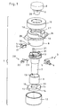
- Fig. 1
- eine Explosionszeichnung eines erfindungsgemäßen Kupplungsmechanismus;
- Fig. 2
- eine Draufsicht auf den zusammengesetzten Kupplungsmechanismus gemäß
Fig. 1 im unverrasteten Zustand, jedoch ohne Abdeckkappe und Kupplungsstecker; - Fig. 3
- eine perspektivische Seitenansicht des Kupplungsmechanismus gemäß
Fig. 2 , jedoch mit Kupplungsstecker, aber ohne Außenhülse; - Fig. 4
- eine Ansicht gemäß
Fig. 2 , jedoch ohne Abdeckkappe; jedoch den Kupplungsmechanismus im verrasteten Zustand darstellend; - Fig. 5
- eine perspektivische Seitenansicht des Kupplungsmechanismus gemäß
Fig. 4 , jedoch mit Kupplungsstecker, aber ohne Außenhülse; - Fig. 6
- einen Längsschnitt entlang der Linie VI-VI gemäß
Fig. 2 , jedoch mit Kupplungsstecker; - Fig. 7
- einen Längsschnitt entlang der Linie VII-VII gemäß
Fig. 2 , jedoch mit Kupplungsstecker und Abdeckkappe; - Fig. 8
- einen Längsschnitt entlang der Linie VIII-VIII gemäß
Fig. 4 , jedoch mit Kupplungsstecker; - Fig. 9
- einen Längsschnitt entlang der Linie IX-IX gemäß
Fig. 4 , jedoch mit Kupplungsstecker und Abdeckkappe - Fig. 10
- eine vergrößerte Ansicht des Details X gemäß
Fig. 6 in der sperrenden und freigebenden Stellung; - Fig.11
- eine perspektivische Seitenansicht des zusammengesetzten Kupplungsmechanismus gemäß
Fig. 1 im unverrasteten Zustand, jedoch ohne Abdeckkappe und Außenhülse und - Fig. 12
- eine Ansicht gemäß
Fig. 11 , jedoch den Kupplungsmechanismus im verrasteten Zustand darstellend. - Der in den Abbildungen
Fig. 1 bis Fig. 12 dargestellte Kupplungsmechanismus besteht im Wesentlichen aus einer Kupplungsaufnahme 1 und einem in der Kupplungsaufnahme 1 über eine Rastverbindung 3 verrastend festlegbaren Kupplungsstecker 2, wobei die Rastverbindung 3 bei der dargestellten Ausführungsform aus zwei über jeweils ein Federelement 4 in Verrastungsrichtung federbelasteten Rasthaken 5 sowie zwei am Kupplungsstecker 2 angeordneten Rastaufnahme 6 zur Aufnahme der mindestens zwei Rasthaken 5 besteht. Bei der dargestellten Ausführungsform sind die Rastaufnahmen 6 als vom Kupplungsstecker 2 radial nach außen abstehende Stege 6 ausgebildet. - Wie aus den Abbildungen ersichtlich, ist die Rastverbindung 3 so ausgebildet, dass die Rasthaken 5 an der Kupplungsaufnahme 1 und die Rastaufnahmen 6 am Kupplungsstecker 2 angeordnet sind.
- Derartige Kupplungsmechanismen werden vorzugsweise verwendet, um zwei medizinische Instrumente, beispielsweise ein endoskopisches Instrument und eine Endoskop-Optik, gas- und flüssigkeitsdicht miteinander zu verbinden.
- Wie insbesondere aus der Explosionszeichnung gemäß
Fig. 1 ersichtlich, besteht die Kupplungsaufnahme 1 im Wesentlichen aus einer Innenhülse 7, einer von der Kupplungsseite her auf die Innenhülse 7 aufsetzbaren und diese koaxial umgebenden Außenhülse 8, einem vom freien unteren Ende auf die Innenhülse 7 aufschiebbaren und diese koaxial umgebenden Federelement 9 sowie einem ebenfalls vom freien unteren Ende auf die Innenhülse 7 aufschiebbaren Ring 10. Beidseitig abgeschlossen wird diese mehrteilig aufgebaute Kupplungsaufnahme 1 über eine auf die Außenhülse 8 aufsetzbare obere Abdeckkappe 11 sowie eine vom freien unteren Ende auf die Innenhülse 7 aufschiebbare untere Abschlusskappe 12. - Wie weiterhin aus
Fig. 1 in Zusammenschau mit den AbbildungenFig. 7 und 9 ersichtlich, sind die Innenhülse 7 und die Außenhülse 8 gegeneinander über das als Druck- und Torsionsfeder ausgebildete Federelement 9 verdrehbar miteinander gekoppelt. Zu diesem Zweck sind am Federelement 9 zwei Zapfen 13 angeformt, über die das Federelement 9 einerseits in einer Zapfenaufnahme 14 an der Innenhülse 7 und andererseits in einer Zapfenaufnahme 14 am Ring 10 festlegbar ist. Weiterhin sind am Ring 10 radial nach außen abstehende Vorsprünge 15 ausgebildet, die im zusammengesetzten Zustand der Kupplungsaufnahme 1 in korrespondierende Ausnehmungen 16 in der Außenhülse 8 eingreifen. - Das eigentliche Koppeln der Kupplungsaufnahme 1 mit dem Kupplungsstecker 2 mittels der Rastverbindung 3 erfolgt über an den Rasthaken 5 ausgebildete, nach innen weisende Rastnasen 17, die im verrasteten Zustand die als Stege 6 ausgebildete Rastaufnahme 6 des Kupplungssteckers 2 hintergreifen, wie dies den Abbildungen
Fig. 7, 9 und12 zu entnehmen ist. - Um die Rasthaken zwischen einer die Kupplungsteile 1 und 2 miteinander verrastenden und einer diese wieder freigebenden Stellung verstellen zu können, sind die Rasthaken 5 radial verschiebbar so in Führungen 18 der Außenhülse 8 gelagert, dass sich die die Rasthaken 5 in Verrastungsrichtung vorspannenden Federelemente 4 einerseits an der Innenseite der Abdeckkappe 11 abstützen und andererseits an den Rasthaken 5 anliegen, um diese radial nach innen zu drücken, bis die Rastnasen 17 der Rasthaken 5 im mit dem Kupplungsstecker 2 verrasteten Zustand die Stege 6 des Kupplungssteckers 2 hintergreifen. Die Verschiebung der Rasthaken 5 radial nach innen wird im mit dem Kupplungsstecker 2 verrasteten Zustand dadurch begrenzt, dass die Rasthaken 5 innenseitig an einer Anlagefläche 19 der Innenhülse 7 zur Anlage kommen. Diese Anlagefläche 19 der Innenhülse 7 ist, wie insbesondere aus
Fig. 1 ersichtlich als unrunde Kulissenbahn ausgebildet. - Als Besonderheit weist der dargestellte Kupplungsmechanismus einen Sicherungsmechanismus 20 auf, über den die Rastverbindung 3 aktivierbar ist. Der Sicherungsmechanismus 20 dient dazu, ein versehentliches Verrasten der Rastverbindung 3 ohne eingesetztes Instrument zu verhindern. Wie aus den Abbildungen
Fig. 1 ,3 ,5 ,6 und 8 sowie insbesondereFig. 10 ersichtlich, ist der Sicherungsmechanismus 20 bei der dargestellten Ausführungsform als aus einem axial verschiebbaren Stift 21 und einem mit dem Stift 21 in Wirkverbindung stehendes radial verschiebbares Klemmelement 22 ausgebildet, wobei das Klemmelement 22 über ein vorteilhafterweise als Federblech ausgebildetes Federelement 23 in die den Sicherungsmechanismus 20 sperrende Richtung vorgespannt ist. - Um das Zusammenspiel des axial verschiebbaren Stifts 21 mit dem radial verschiebbares Klemmelement 22 zu erleichtern und das Überführen des Sicherungsmechanismus 20 von der die Rastverbindung 3 sperrenden in die die Rastverbindung 3 freigebende Stellung zu vereinfachen, sind an miteinander in Wirkverbindung stehenden Kontaktflächen des Stifts 21 und des Klemmelmenets 22 korrespondierende Anlaufschrägen 24 ausgebildet, die vorzugsweise einen Winkel von 45° aufweisen, wodurch der Stift 21 beim Anlaufen gegen das Klemmelement 22 das Klemmelement 22 automatisch radial nach innen drückt.
- Das Trennen der beiden über den Kupplungsmechanismus miteinander verbundenen Bauteile 1 und 2 ist die Rastverbindung 3 über einen mit den Rasthaken 5 in Wirkverbindung stehenden Auslösemechanismus 25 wieder aufhebbar.
- Wie insbesondere aus den Abbildungen
Fig. 1 ,2, 4 sowie 11 und 12 ersichtlich, besteht der Auslösemechanismus 25 aus der als unrunde Kulissenbahn ausgebildeten Anlagefläche 19 der Innenhülse 7 sowie aus an der Außenhülse 8 ausgebildete, radial nach außen vorstehenden Nocken 26, über die die Außenhülse 8 gegenüber der Innenhülse 7 verdrehbar ist. Beim Verdrehen der Außenhülse 8 verfahren die im verrasteten Zustand des Kupplngsmechanismus an der Anlagefläche 19 anliegenden Rasthaken 5 entlang dieser unrunden Kulissenbahn und werden während dieses Verfahrens radial nach außen gedrückt, bis die Rastnasen 17 der Rasthaken 5 die Stege 6 des Kupplungssteckers 2 nicht mehr hintergreifen und die Kopplung der Bauteile 1 und 2 sowie die Innenhülse 7 freigeben. - Der Zusammenbau sowie das Betätigen des Kupplungsmechanismus wird nachfolgend anhand der Abbildungen
Fig.1 und6 bis 9 erläutert: - Im ersten Montageschritt wird der aus dem Stift 21, dem Klemmelement 22 sowie dem Federelement 23 bestehende Sicherungsmechanismus 20 an der Innenhülse 7 festgelegt.
- Nachfolgend wird vom kupplungsfernen unteren Ende der Innenhülse 7 her zunächst das als Druck- und Torsionsfeder ausgebildete Federelement 9 auf die Innenhülse 7 aufgeschoben, bis der Zapfen 13 des Federelements 9 in die Zapfenaufnahme 14 der Innenhülse 7 eingreift. Im nächsten Schritt wird ebenfalls vom kupplungsfernen unteren Ende der Innenhülse 7 her der Ring 10 auf die Innenhülse 1 aufgeschoben, bis der Zapfen 13 des Federelements 9 in die Zapfenaufnahme 14 des Rings 10 eingreift.
- Auf diese Baugruppe wird nunmehr vom oberen kupplungsseitigen Ende der Innenhülse 7 her die Außenhülse 8 auf die Innenhülse 7 aufgesetzt, bis die am Ring 10 angeformten Vorsprünge 15 in die Ausnehmungen 16 der Außenhülse 8 eingreifen. Zusammengehalten wird diese über das Federelement 9 gegeneinander verdrehbare Kopplung der Innenhülse 7 mit der Außenhülse 8 über die vom freien unteren Ende auf die Innenhülse 7 aufschiebbare und auf die Außenhülse 8 aufschraubbare Abschlusskappe 12.
- Im nächsten Montageschritt werden die Rasthaken 5 und die Federelemente 4 in die Führungen 18 der Außenhülse 8 eingesetzt und abschließend vom kopplungsseitigen Ende her die obere Abdeckkappe 11 so auf die Außenhülse 8 aufgesetzt und mit dieser beispielsweise durch Verschweißen verbunden, dass sich die Federelemente 4 rückseitig an der Innenseite der Abdeckkappe 11 abstützen und die Rasthaken 5 radial einwärts gegen die Innenhülse 1 drücken.
- In diesem zusammengesetzten Zustand der Kupplungsaufnahme 1 drückt das Federelement 23 des Sicherungsmechanismus das radial verschiebbare Klemmelement 22 radial nach außen in einen Freistich 27 in der Außenhülse 8, wie dies in
Fig. 6 dargestellt ist. In dieser Stellung sperrt der Sicherungsmechanismus 20 die Rastverbindung 3 gegen ein versehentliches Verrasten. - Der Kupplungsmechanismus ist nunmehr bereit die verrastende Verbindung zwischen dem Kupplungsstecker 2 in der Kupplungsaufnahme 1 zu ermöglichen. Bei der dargestellten Ausführungsform sind die ineinander zu fügenden Abschnitte des Kupplungssteckers 2 und der Kupplungsaufnahme 1 als Konus 28 und Gegenkonus 29 ausgebildet. Selbstverständlich sind auch andere Formen, wie rohrförmige Kupplungsabschnitte möglich.
- Um eine lagegenaue und verdrehsichere Platzierung der Bauteile Kupplungsaufnahme 1 und Kupplungsstecker 2 zueinander zu gewährleisten, sind, wie aus
Fig. 11 und 12 ersichtlich, am Kupplungsstecker 2 und an der Kupplungsaufnahme 1 miteinander korrespondierende Führungs- und/oder Zentrierelemente 30 ausgebildet, die bei der dargestellten Ausführungsform als Zentrierzapfen 31 und Aufnahmenut 32 ausgebildet sind. - Ausgehend von der in
Fig. 6 und11 dargestellten Ausgangslage, in der der Kupplungsstecker 2 und die Kupplungsaufnahme 1 über die Führungs- und/oder Zentrierelemente 28 zueinander ausgerichtet sind und der Kupplungsstecker 2 mit der Unterseite der Rastaufnahme 6 auf dem Stift 21 des Sicherungsmechanismus 20 aufliegt, wird der Kupplungsstecker 2 nachfolgend zur Verrastung mit der Kupplungsaufnahme 1 nach unten in die Kupplungsaufnahme 1 gedrückt. Diese über den Kupplungsstecker 2 auf den Stift 21 des Sicherungsmechanismus 20 ausgeübte axiale Druckkraft bewirkt, dass, wie inFig. 10 dargestellt, das Klemmelement 22 über die aneinander anliegenden Anlaufschrägen 24 des Stifts 21 und des Klemmelements 22 radial nach innengedrückt wird und den Freistich 27 der Außenhülse 8 wieder freigibt. - Dieses Entriegeln des Sicherungsmechanismus 20 bewirkt, dass der Kupplungsstecker 2 weiter in die Kupplungsaufnahme 1 hineingedrückt werden kann und die Rastverbindung 3 aktiviert wird. Sobald der Kupplungsstecker 2 ausreichend tief in die Kupplungsaufnahme 1 eingetreten ist, werden die über die Federelemente 4 in Verrastungsrichtung vorgespannten Rasthaken 5 radial nach innen gedrückt, bis die Rastnasen 17 der Kupplungsaufnahme 1 die Stege 6 des Kupplungssteckers 2 hintergreifen und den Kupplungsstecker 2 gas- und flüssigkeitsdicht in der Kupplungsaufnahme 1 fixieren.
- Zum Lösen der Rastverbindung wird die Außenhülse 8 über die beiden insbesondere in
Fig. 2 und 4 dargestellten Nocken 26 gegenüber der Innenhülse 7 verdreht, bis die an der Anlagefläche 19 de Innenhülse 1 anliegenden Rasthaken 5 durch die unrunde Kulissenbahn der Anlagefläche 19 radial nach außen gedrückt werden und die Rastnasen 17 der Rasthaken 5 die Stege 6 des Kupplungssteckers 2 treten. - Durch das als Druck- und Torsionsfeder ausgebildete Federelement 9, das einerseits die Gegeneinanderverdrehung von Innenhülse 7 und Außenhülse 8 ermöglicht und andererseits als axialer Toleranzausgleich bei der Verrastung mit dem Kupplungsstecker 2 dient, wird die Außenhülse 8 aufgrund der Torsionskraft automatisch wieder in die Ausgangslage zurück gedreht, sobald die Rastverbindung 3 gelöst wird. Diese Rückdrehung der Außenhülse 8 bewirkt ein axiales Anheben des Kupplungssteckers 2 heraus aus der Kupplungsaufnahme 1.
- In diesem entriegelten Zustand drückt das Federelement 23 das Klemmelement 22 des Sicherungsmechanismus 20 wieder radial nach außen in den Freistich 27 der Außenhülse 8, wodurch der Stift 21 wieder die in
Fig. 6 dargestellte Position einnimmt und der Sicherungsmechanismus 20 die Rastverbindung 3 sperrt. - Ein solchermaßen ausgestalteter Kupplungsmechanismus zeichnet sich dadurch aus, dass er durch bloßes Zusammendrücken der miteinander zu verbindenden Bauteile 1 und 2 eine sichere sowie gas- und flüssigkeitsdichte Verbindung bewirkt.
Bezugszeichenliste 1 Kupplungsaufnahme 18 Führung 2 Kupplungsstecker 19 Anlagefläche 3 Rastverbindung 20 Sicherungsmechanismus 4 Federelement 21 Stift 5 Rasthaken 22 Klemmelement 6 Rastaufnahme/Steg 23 Federelement 7 Innenhülse 24 Anlaufschräge 8 Außenhülse 25 Auslösemechanismus 9 Federelement 26 Nocke 10 Ring 27 Freistich 11 Abdeckkappe 28 Konus 12 Abschlusskappe 29 Gegenkonus 13 Zapfen 30 Führungs- / Zentrierelemente 14 Zapfenaufnahme 31 Zentrierzapfen 15 Vorsprung 32 Aufnahmenut 16 Ausnehmung 17 Rastnase
Claims (12)
- Kupplungsmechanismus, insbesondere für medizinische Instrumente, mit einem Kupplungsstecker (2) und einer Kupplungsaufnahme (1) zur Aufnahme des Kupplungssteckers (2), wobei die Kupplungsaufnahme (1) und der Kupplungsstecker (2) über mindestens eine federbelastete Rastverbindung (3) aneinander festlegbar sind, wobei die Rastverbindung (3) über einen Sicherungsmechanismus (20) aktivierbar ist, die über den in die Kupplungsaufnahme (1) eingesteckten Kupplungsstecker (2) freigebbar ist,
dadurch gekennzeichnet,
dass der Sicherungsmechanismus (20) als in der Kupplungsaufnahme (1) angeordnetes federbelastetes Rastelement ausgebildet ist. - Kupplungsmechanismus nach Anspruch 1, dadurch gekennzeichnet, dass das Rastelement aus einem axial verschiebbaren Stift (21) und einem mit dem Stift (21) in Wirkverbindung stehenden radial verschiebbaren Klemmelement (22) besteht, wobei das Klemmelement (22) über ein Federelement (23) in die den Sicherungsmechanismus (20) sperrende Richtung vorgespannt ist.
- Kupplungsmechanismus nach Anspruch 2, dadurch gekennzeichnet, dass am Stift (21) und am Klemmelement (22) miteinander korrespondierende Anlaufschrägen (24) ausgebildet sind.
- Kupplungsmechanismus nach einem der Ansprüche 1 bis 3, dadurch gekennzeichnet, dass die Rastverbindung (3) aus mindestens einem an der Kupplungsaufnahme (1) angeordneten und über mindestens ein Federelement (4) in Verrastungsrichtung federbelasteten Rasthaken (5) sowie mindestens einer am Kupplungsstecker (2) angeordneten Rastaufnahme (6) zur Aufnahme des mindestens einen Rasthakens (5) besteht.
- Kupplungsmechanismus nach einem der Ansprüche 1 bis 4 dadurch gekennzeichnet, dass die Kupplungsaufnahme (1) eine Innenhülse (7) und eine die Innenhülse (7) zumindest teilweise koaxial umgebende Außenhülse (8) umfasst, wobei die Innenhülse (7) und die Außenhülse (8) über ein Federelement (9), insbesondere eine Druckfeder, gegeneinander verdrehbar miteinander gekoppelt sind.
- Kupplungsmechanismus nach Anspruch 4 oder 5, dadurch gekennzeichnet, dass an den Rasthaken (5) nach innen weisende Rastnasen (17) ausgebildet sind, die im mit dem Kupplungsstecker (2) verrasteten Zustand als Stege (6) ausgebildete Rastaufnahmen (6) am Kupplungsstecker (2) hintergreifen.
- Kupplungsmechanismus nach Anspruch 5 oder 6, dadurch gekennzeichnet, dass die Rasthaken (5) radial verschiebbar in der Außenhülse (8) gelagert sind und im mit dem Kupplungsstecker (2) verrasteten Zustand innenseitig an eine Anlagefläche (19) der Innenhülse (7) anliegen.
- Kupplungsmechanismus nach einem der Ansprüche 1 bis 7, dadurch gekennzeichnet, dass die Rastverbindung (3) über einen mit dem mindestens einen Rasthaken (5) in Wirkverbindung stehenden Auslösemechanismus (25) wieder aufhebbar ist.
- Kupplungsmechanismus nach Anspruch 8, dadurch gekennzeichnet, dass zur Ausbildung des Auslösemechanismus (25) die Anlagefläche (19) der Innenhülse (7), an der die Rasthaken (5) im verrasteten Zustand anliegen, als unrunde Kulissenbahn ausgebildet ist.
- Kupplungsmechanismus nach einem der Ansprüche 5 bis 9, dadurch gekennzeichnet, dass an der Außenhülse (8) radial nach außen vorstehende Nocken (26) ausgebildet sind.
- Kupplungsmechanismus nach einem der Ansprüche 1 bis 10, dadurch gekennzeichnet, dass am Kupplungsstecker (2) und an der Kupplungsaufnahme (1) miteinander korrespondierende Führungs- und/oder Zentrierelemente (30) ausgebildet sind.
- Kupplungsaufnahme zur Aufnahme eines Kupplungssteckers (2) eines Kupplungsmechanismus, insbesondere nach einem der Ansprüche 1 bis 11, wobei die Kupplungsaufnahme (1) und der Kupplungsstecker (2) über mindestens eine federbelastete Rastverbindung (3) aneinander festlegbar sind und wobei die Rastverbindung (3) über einen Sicherungsmechanismus (20) aktivierbar ist, die über den in die Kupplungsaufnahme (1) eingesteckten Kupplungsstecker (2) freigebbar ist,
dadurch gekennzeichnet,
dass der Sicherungsmechanismus (20) als in der Kupplungsaufnahme (1) angeordnetes federbelastetes Rastelement ausgebildet ist.
Applications Claiming Priority (1)
| Application Number | Priority Date | Filing Date | Title |
|---|---|---|---|
| DE102007008422A DE102007008422A1 (de) | 2007-02-21 | 2007-02-21 | Kupplungsmechanismus |
Publications (2)
| Publication Number | Publication Date |
|---|---|
| EP1969990A1 true EP1969990A1 (de) | 2008-09-17 |
| EP1969990B1 EP1969990B1 (de) | 2009-11-18 |
Family
ID=39327378
Family Applications (1)
| Application Number | Title | Priority Date | Filing Date |
|---|---|---|---|
| EP08002500A Not-in-force EP1969990B1 (de) | 2007-02-21 | 2008-02-12 | Kupplungsmechanismus |
Country Status (4)
| Country | Link |
|---|---|
| US (1) | US7871218B2 (de) |
| EP (1) | EP1969990B1 (de) |
| AT (1) | ATE448730T1 (de) |
| DE (2) | DE102007008422A1 (de) |
Cited By (1)
| Publication number | Priority date | Publication date | Assignee | Title |
|---|---|---|---|---|
| WO2015049037A1 (de) * | 2013-10-02 | 2015-04-09 | Olympus Winter & Ibe Gmbh | Schaft eines endoskopes |
Families Citing this family (28)
| Publication number | Priority date | Publication date | Assignee | Title |
|---|---|---|---|---|
| DE102006010316A1 (de) | 2006-03-07 | 2007-09-13 | Karl Storz Gmbh & Co. Kg | Kupplungsmechanismus |
| US20120161404A1 (en) * | 2009-09-17 | 2012-06-28 | The Gleason Works | Workholding apparatus for machine tool |
| IL209253A (en) * | 2010-11-11 | 2017-05-29 | Plasan Sasa Ltd | Connection mechanism |
| US8608502B2 (en) | 2012-05-08 | 2013-12-17 | Otter Products, Llc | Connection mechanism |
| US20150201723A1 (en) | 2013-02-01 | 2015-07-23 | Treefrog Developments, Inc. | Encasements for an electronic device having a biometric scanner |
| US9869423B2 (en) | 2013-03-15 | 2018-01-16 | Otter Products, Llc | Releasable mount apparatus and system with lock switch |
| US9611881B2 (en) | 2013-03-15 | 2017-04-04 | Otter Products, Llc | Releasable mount apparatus and system |
| US10078346B2 (en) | 2013-09-21 | 2018-09-18 | Otter Products, Llc | Magnetic mounting system for electronic device |
| US20150150574A1 (en) * | 2013-12-04 | 2015-06-04 | Covidien Lp | Adapter direct drive push button retention mechanism |
| US9295174B2 (en) | 2014-01-07 | 2016-03-22 | Otter Products, Llc | Protective enclosure for an electronic device |
| US9593700B2 (en) * | 2014-10-03 | 2017-03-14 | Kurt Kevin Bynum | Self-locking plug |
| US9909446B2 (en) * | 2014-10-03 | 2018-03-06 | Kurt Kevin Bynum | Self-locking plug |
| DE102014115873A1 (de) * | 2014-10-31 | 2016-05-04 | Karl Storz Gmbh & Co. Kg | Zerlegbares medizinisches Instrument |
| CN105518372B (zh) * | 2014-12-30 | 2017-06-23 | 深圳市大疆创新科技有限公司 | 快拆连接结构、支架结构、以及遥控器 |
| US9986805B2 (en) | 2015-03-30 | 2018-06-05 | Otter Products, Llc | Protective enclosure for an electronic device |
| US10058155B2 (en) | 2015-07-19 | 2018-08-28 | Otter Products, Llc | Protective case system |
| US10623043B2 (en) | 2018-01-23 | 2020-04-14 | Otter Products, Llc | Protective case for electronic device |
| US10694835B2 (en) | 2018-03-15 | 2020-06-30 | Otter Products, Llc | Protective case for use with device grip |
| US10750844B2 (en) | 2018-03-15 | 2020-08-25 | Otter Products, Llc | Protective case for use with device grip |
| US11202014B2 (en) | 2018-07-06 | 2021-12-14 | Medos International Sari | Camera scope electronic variable angle of view |
| US11032481B2 (en) | 2018-07-06 | 2021-06-08 | Medos International Sarl | Camera scope electronic variable prism |
| USD897329S1 (en) | 2019-07-02 | 2020-09-29 | Otter Products, Llc | Case for a smartphone |
| US12433391B2 (en) | 2021-03-29 | 2025-10-07 | Otter Products, Llc | Collapsible and extendable device grip |
| EP4346545A4 (de) * | 2021-06-03 | 2025-03-26 | Saban Ventures Pty Limited | Anschlussverbinder für medizinische vorrichtung |
| CN113568259A (zh) * | 2021-08-25 | 2021-10-29 | 深圳市乐其网络科技有限公司 | 拆装组件 |
| JP7807337B2 (ja) * | 2022-07-27 | 2026-01-27 | 富士フイルム株式会社 | 内視鏡の接続構造 |
| US12575654B2 (en) | 2022-11-09 | 2026-03-17 | Otter Products, Llc | Protective case with grip and stand |
| CN117092805B (zh) * | 2023-07-21 | 2026-02-03 | 卓外(上海)医疗电子科技有限公司 | 内窥镜用光学卡口机构 |
Citations (3)
| Publication number | Priority date | Publication date | Assignee | Title |
|---|---|---|---|---|
| DE3014116A1 (de) * | 1979-04-12 | 1980-10-16 | Olympus Optical Co | Kupplungsstueck zum anschluss von zubehoerteilen an ein okular eines endoskops |
| DE4425705A1 (de) * | 1994-07-01 | 1996-01-11 | Storz Karl Gmbh & Co | Endoskopisches Instrument |
| DE19712645C1 (de) * | 1997-03-26 | 1998-10-15 | Zeiss Carl Fa | Kupplung zum Kuppeln zweier optischer Einrichtungen |
Family Cites Families (15)
| Publication number | Priority date | Publication date | Assignee | Title |
|---|---|---|---|---|
| GB1395120A (en) * | 1973-07-10 | 1975-05-21 | Amalgamated Dental Co Ltd | Couplings for dental handpieces |
| JPH0618123Y2 (ja) * | 1989-11-11 | 1994-05-11 | 日東工器株式会社 | 管継手のソケット |
| US5033777A (en) * | 1987-09-15 | 1991-07-23 | Colder Products Company | Male insert member having integrally molded part line free seal |
| US5464300A (en) * | 1993-04-29 | 1995-11-07 | Crainich; Lawrence | Medical instrument and coupling apparatus for same |
| KR19980701256A (ko) * | 1995-01-06 | 1998-05-15 | 브라이안 블렌쿠쉬 | 커플링 밸브조립체 |
| US5695223A (en) * | 1995-03-29 | 1997-12-09 | Fred Knapp Engraving Co., Inc. | Quick-disconnect tube coupler with use-enhancing features |
| EP0747174B1 (de) * | 1995-05-30 | 1997-03-26 | Jessie Chow | Kupplingsmechanismus für eine Steckschlüsselverlängerung |
| US5836781A (en) * | 1997-02-28 | 1998-11-17 | Itt Manufacturing Enterprises, Inc. | Connector quick coupling/decoupling mechanism |
| DE19724282C1 (de) * | 1997-06-09 | 1998-10-22 | Aesculap Ag & Co Kg | Schnellkupplung für ein in ein Rohr einsetzbares Instrument insbesondere für eine Trokarhülse |
| DE19844583A1 (de) * | 1998-09-29 | 2000-04-06 | Raymond A & Cie | Lösbare Steckverbindung für Hochdruckleitungen |
| US6908222B2 (en) * | 2001-05-30 | 2005-06-21 | Premark Feg L.L.C. | Attachment mechanism |
| US6672628B2 (en) * | 2002-02-20 | 2004-01-06 | Masco Corporation Of Indiana | Quick connect hose coupling |
| US6767155B2 (en) * | 2002-04-05 | 2004-07-27 | Eastman Kodak Company | High stability latch mechanism |
| US7153296B2 (en) * | 2003-11-07 | 2006-12-26 | Mitchell Martin S | Releasable tubing connector |
| US7066678B2 (en) * | 2003-11-18 | 2006-06-27 | Lite-On Technology Corporation | Locking method and mechanism |
-
2007
- 2007-02-21 DE DE102007008422A patent/DE102007008422A1/de not_active Withdrawn
-
2008
- 2008-02-12 EP EP08002500A patent/EP1969990B1/de not_active Not-in-force
- 2008-02-12 DE DE502008000185T patent/DE502008000185D1/de active Active
- 2008-02-12 AT AT08002500T patent/ATE448730T1/de active
- 2008-02-20 US US12/034,373 patent/US7871218B2/en not_active Expired - Fee Related
Patent Citations (4)
| Publication number | Priority date | Publication date | Assignee | Title |
|---|---|---|---|---|
| DE3014116A1 (de) * | 1979-04-12 | 1980-10-16 | Olympus Optical Co | Kupplungsstueck zum anschluss von zubehoerteilen an ein okular eines endoskops |
| DE4425705A1 (de) * | 1994-07-01 | 1996-01-11 | Storz Karl Gmbh & Co | Endoskopisches Instrument |
| DE4425705C2 (de) | 1994-07-01 | 2002-08-01 | Storz Karl Gmbh & Co Kg | Endoskopisches Instrument |
| DE19712645C1 (de) * | 1997-03-26 | 1998-10-15 | Zeiss Carl Fa | Kupplung zum Kuppeln zweier optischer Einrichtungen |
Cited By (2)
| Publication number | Priority date | Publication date | Assignee | Title |
|---|---|---|---|---|
| WO2015049037A1 (de) * | 2013-10-02 | 2015-04-09 | Olympus Winter & Ibe Gmbh | Schaft eines endoskopes |
| CN105578945A (zh) * | 2013-10-02 | 2016-05-11 | 奥林匹斯冬季和Ibe有限公司 | 内窥镜的杆 |
Also Published As
| Publication number | Publication date |
|---|---|
| US7871218B2 (en) | 2011-01-18 |
| ATE448730T1 (de) | 2009-12-15 |
| US20080199252A1 (en) | 2008-08-21 |
| EP1969990B1 (de) | 2009-11-18 |
| DE102007008422A1 (de) | 2008-08-28 |
| DE502008000185D1 (de) | 2009-12-31 |
Similar Documents
| Publication | Publication Date | Title |
|---|---|---|
| EP1969990B1 (de) | Kupplungsmechanismus | |
| EP1537829B1 (de) | Medizinisches Instrument mit Instrumenteneinsatz und Mittel zur Blockierung des beweglichen Griffteils | |
| DE19831897C2 (de) | Steckkupplung zum Verbinden zweier Fluidleitungen | |
| DE2827847C3 (de) | Schnellkupplung, insbesondere für Sanitärgegenstände | |
| DE2840728C2 (de) | HF-Koaxialsteckverbindung | |
| EP2008607B1 (de) | Kupplungsvorrichtung zum Festlegen medizinischer Instrumente an einer Haltevorrichtung | |
| DE68903350T2 (de) | Bajonettschnellkupplung. | |
| DE2906281C2 (de) | Kupplungselement | |
| EP3411099B1 (de) | Injektionsvorrichtung | |
| EP1958660A1 (de) | Bajonett-Luer-Lockverbindung für eine Insulinpumpe | |
| DE8227212U1 (de) | Teilbare Tragbahre | |
| EP2740985A1 (de) | Schnellkupplung mit Sicherheitsverriegelung | |
| EP2843279A2 (de) | Verschlusselement für ein Absperrorgan und Absperrorgan | |
| DE202016008996U1 (de) | Kupplung | |
| DE3124413A1 (de) | Kupplung | |
| DE102012112882B4 (de) | Stechhilfe zur Gewinnung von Körperflüssigkeitsproben | |
| DE2435250C3 (de) | ||
| DE102013016302A1 (de) | Schaft eines Endoskopes | |
| DE102014007123B4 (de) | Verbindungsteil zur Befestigung eines rohr- oder stabförmigen Elements an einem anderen Bauteil | |
| EP1801485B1 (de) | Mehrfachkupplung für Medienleitungen | |
| DE102020126258A1 (de) | Sicherheitsabdeckung zur Kopplung mit einer Injektionsvorrichtung | |
| EP3886734B1 (de) | Schlüssellose werkzeugschaftkopplung | |
| DE19715293A1 (de) | Steckverbindung für Rohrleitungen | |
| DE102007007904B3 (de) | Kupplung für ein Rohrschaftinstrument | |
| DE102011088506A1 (de) | Konnektor-Baugruppe sowie Konnektor-Set |
Legal Events
| Date | Code | Title | Description |
|---|---|---|---|
| PUAI | Public reference made under article 153(3) epc to a published international application that has entered the european phase |
Free format text: ORIGINAL CODE: 0009012 |
|
| AK | Designated contracting states |
Kind code of ref document: A1 Designated state(s): AT BE BG CH CY CZ DE DK EE ES FI FR GB GR HR HU IE IS IT LI LT LU LV MC MT NL NO PL PT RO SE SI SK TR |
|
| AX | Request for extension of the european patent |
Extension state: AL BA MK RS |
|
| 17P | Request for examination filed |
Effective date: 20090227 |
|
| AKX | Designation fees paid |
Designated state(s): AT BE BG CH CY CZ DE DK EE ES FI FR GB GR HR HU IE IS IT LI LT LU LV MC MT NL NO PL PT RO SE SI SK TR |
|
| GRAP | Despatch of communication of intention to grant a patent |
Free format text: ORIGINAL CODE: EPIDOSNIGR1 |
|
| GRAS | Grant fee paid |
Free format text: ORIGINAL CODE: EPIDOSNIGR3 |
|
| GRAA | (expected) grant |
Free format text: ORIGINAL CODE: 0009210 |
|
| AK | Designated contracting states |
Kind code of ref document: B1 Designated state(s): AT BE BG CH CY CZ DE DK EE ES FI FR GB GR HR HU IE IS IT LI LT LU LV MC MT NL NO PL PT RO SE SI SK TR |
|
| REG | Reference to a national code |
Ref country code: GB Ref legal event code: FG4D Free format text: NOT ENGLISH |
|
| REG | Reference to a national code |
Ref country code: CH Ref legal event code: EP |
|
| REG | Reference to a national code |
Ref country code: IE Ref legal event code: FG4D |
|
| REF | Corresponds to: |
Ref document number: 502008000185 Country of ref document: DE Date of ref document: 20091231 Kind code of ref document: P |
|
| REG | Reference to a national code |
Ref country code: NL Ref legal event code: VDEP Effective date: 20091118 |
|
| LTIE | Lt: invalidation of european patent or patent extension |
Effective date: 20091118 |
|
| PG25 | Lapsed in a contracting state [announced via postgrant information from national office to epo] |
Ref country code: SE Free format text: LAPSE BECAUSE OF FAILURE TO SUBMIT A TRANSLATION OF THE DESCRIPTION OR TO PAY THE FEE WITHIN THE PRESCRIBED TIME-LIMIT Effective date: 20091118 Ref country code: ES Free format text: LAPSE BECAUSE OF FAILURE TO SUBMIT A TRANSLATION OF THE DESCRIPTION OR TO PAY THE FEE WITHIN THE PRESCRIBED TIME-LIMIT Effective date: 20100228 Ref country code: FI Free format text: LAPSE BECAUSE OF FAILURE TO SUBMIT A TRANSLATION OF THE DESCRIPTION OR TO PAY THE FEE WITHIN THE PRESCRIBED TIME-LIMIT Effective date: 20091118 Ref country code: NO Free format text: LAPSE BECAUSE OF FAILURE TO SUBMIT A TRANSLATION OF THE DESCRIPTION OR TO PAY THE FEE WITHIN THE PRESCRIBED TIME-LIMIT Effective date: 20100218 Ref country code: IS Free format text: LAPSE BECAUSE OF FAILURE TO SUBMIT A TRANSLATION OF THE DESCRIPTION OR TO PAY THE FEE WITHIN THE PRESCRIBED TIME-LIMIT Effective date: 20100318 Ref country code: LT Free format text: LAPSE BECAUSE OF FAILURE TO SUBMIT A TRANSLATION OF THE DESCRIPTION OR TO PAY THE FEE WITHIN THE PRESCRIBED TIME-LIMIT Effective date: 20091118 |
|
| PG25 | Lapsed in a contracting state [announced via postgrant information from national office to epo] |
Ref country code: CY Free format text: LAPSE BECAUSE OF FAILURE TO SUBMIT A TRANSLATION OF THE DESCRIPTION OR TO PAY THE FEE WITHIN THE PRESCRIBED TIME-LIMIT Effective date: 20091118 Ref country code: PL Free format text: LAPSE BECAUSE OF FAILURE TO SUBMIT A TRANSLATION OF THE DESCRIPTION OR TO PAY THE FEE WITHIN THE PRESCRIBED TIME-LIMIT Effective date: 20091118 Ref country code: LV Free format text: LAPSE BECAUSE OF FAILURE TO SUBMIT A TRANSLATION OF THE DESCRIPTION OR TO PAY THE FEE WITHIN THE PRESCRIBED TIME-LIMIT Effective date: 20091118 Ref country code: SI Free format text: LAPSE BECAUSE OF FAILURE TO SUBMIT A TRANSLATION OF THE DESCRIPTION OR TO PAY THE FEE WITHIN THE PRESCRIBED TIME-LIMIT Effective date: 20091118 Ref country code: HR Free format text: LAPSE BECAUSE OF FAILURE TO SUBMIT A TRANSLATION OF THE DESCRIPTION OR TO PAY THE FEE WITHIN THE PRESCRIBED TIME-LIMIT Effective date: 20091118 |
|
| REG | Reference to a national code |
Ref country code: IE Ref legal event code: FD4D |
|
| PG25 | Lapsed in a contracting state [announced via postgrant information from national office to epo] |
Ref country code: NL Free format text: LAPSE BECAUSE OF FAILURE TO SUBMIT A TRANSLATION OF THE DESCRIPTION OR TO PAY THE FEE WITHIN THE PRESCRIBED TIME-LIMIT Effective date: 20091118 Ref country code: EE Free format text: LAPSE BECAUSE OF FAILURE TO SUBMIT A TRANSLATION OF THE DESCRIPTION OR TO PAY THE FEE WITHIN THE PRESCRIBED TIME-LIMIT Effective date: 20091118 Ref country code: RO Free format text: LAPSE BECAUSE OF FAILURE TO SUBMIT A TRANSLATION OF THE DESCRIPTION OR TO PAY THE FEE WITHIN THE PRESCRIBED TIME-LIMIT Effective date: 20091118 Ref country code: DK Free format text: LAPSE BECAUSE OF FAILURE TO SUBMIT A TRANSLATION OF THE DESCRIPTION OR TO PAY THE FEE WITHIN THE PRESCRIBED TIME-LIMIT Effective date: 20091118 Ref country code: IE Free format text: LAPSE BECAUSE OF FAILURE TO SUBMIT A TRANSLATION OF THE DESCRIPTION OR TO PAY THE FEE WITHIN THE PRESCRIBED TIME-LIMIT Effective date: 20091118 Ref country code: BG Free format text: LAPSE BECAUSE OF FAILURE TO SUBMIT A TRANSLATION OF THE DESCRIPTION OR TO PAY THE FEE WITHIN THE PRESCRIBED TIME-LIMIT Effective date: 20100218 |
|
| BERE | Be: lapsed |
Owner name: KARL STORZ G.M.B.H. & CO. KG Effective date: 20100228 |
|
| PG25 | Lapsed in a contracting state [announced via postgrant information from national office to epo] |
Ref country code: SK Free format text: LAPSE BECAUSE OF FAILURE TO SUBMIT A TRANSLATION OF THE DESCRIPTION OR TO PAY THE FEE WITHIN THE PRESCRIBED TIME-LIMIT Effective date: 20091118 Ref country code: CZ Free format text: LAPSE BECAUSE OF FAILURE TO SUBMIT A TRANSLATION OF THE DESCRIPTION OR TO PAY THE FEE WITHIN THE PRESCRIBED TIME-LIMIT Effective date: 20091118 |
|
| PLBE | No opposition filed within time limit |
Free format text: ORIGINAL CODE: 0009261 |
|
| STAA | Information on the status of an ep patent application or granted ep patent |
Free format text: STATUS: NO OPPOSITION FILED WITHIN TIME LIMIT |
|
| 26N | No opposition filed |
Effective date: 20100819 |
|
| PG25 | Lapsed in a contracting state [announced via postgrant information from national office to epo] |
Ref country code: GR Free format text: LAPSE BECAUSE OF FAILURE TO SUBMIT A TRANSLATION OF THE DESCRIPTION OR TO PAY THE FEE WITHIN THE PRESCRIBED TIME-LIMIT Effective date: 20100219 Ref country code: MC Free format text: LAPSE BECAUSE OF NON-PAYMENT OF DUE FEES Effective date: 20100301 |
|
| PG25 | Lapsed in a contracting state [announced via postgrant information from national office to epo] |
Ref country code: BE Free format text: LAPSE BECAUSE OF NON-PAYMENT OF DUE FEES Effective date: 20100228 |
|
| PG25 | Lapsed in a contracting state [announced via postgrant information from national office to epo] |
Ref country code: MT Free format text: LAPSE BECAUSE OF FAILURE TO SUBMIT A TRANSLATION OF THE DESCRIPTION OR TO PAY THE FEE WITHIN THE PRESCRIBED TIME-LIMIT Effective date: 20091118 |
|
| PGFP | Annual fee paid to national office [announced via postgrant information from national office to epo] |
Ref country code: FR Payment date: 20110311 Year of fee payment: 4 |
|
| PGFP | Annual fee paid to national office [announced via postgrant information from national office to epo] |
Ref country code: IT Payment date: 20110228 Year of fee payment: 4 |
|
| PG25 | Lapsed in a contracting state [announced via postgrant information from national office to epo] |
Ref country code: LU Free format text: LAPSE BECAUSE OF NON-PAYMENT OF DUE FEES Effective date: 20100212 Ref country code: PT Free format text: LAPSE BECAUSE OF FAILURE TO SUBMIT A TRANSLATION OF THE DESCRIPTION OR TO PAY THE FEE WITHIN THE PRESCRIBED TIME-LIMIT Effective date: 20100418 Ref country code: HU Free format text: LAPSE BECAUSE OF FAILURE TO SUBMIT A TRANSLATION OF THE DESCRIPTION OR TO PAY THE FEE WITHIN THE PRESCRIBED TIME-LIMIT Effective date: 20100519 |
|
| REG | Reference to a national code |
Ref country code: CH Ref legal event code: PL |
|
| GBPC | Gb: european patent ceased through non-payment of renewal fee |
Effective date: 20120212 |
|
| PG25 | Lapsed in a contracting state [announced via postgrant information from national office to epo] |
Ref country code: LI Free format text: LAPSE BECAUSE OF NON-PAYMENT OF DUE FEES Effective date: 20120229 Ref country code: TR Free format text: LAPSE BECAUSE OF FAILURE TO SUBMIT A TRANSLATION OF THE DESCRIPTION OR TO PAY THE FEE WITHIN THE PRESCRIBED TIME-LIMIT Effective date: 20091118 Ref country code: CH Free format text: LAPSE BECAUSE OF NON-PAYMENT OF DUE FEES Effective date: 20120229 |
|
| REG | Reference to a national code |
Ref country code: FR Ref legal event code: ST Effective date: 20121031 |
|
| PG25 | Lapsed in a contracting state [announced via postgrant information from national office to epo] |
Ref country code: IT Free format text: LAPSE BECAUSE OF NON-PAYMENT OF DUE FEES Effective date: 20120212 |
|
| PG25 | Lapsed in a contracting state [announced via postgrant information from national office to epo] |
Ref country code: GB Free format text: LAPSE BECAUSE OF NON-PAYMENT OF DUE FEES Effective date: 20120212 Ref country code: FR Free format text: LAPSE BECAUSE OF NON-PAYMENT OF DUE FEES Effective date: 20120229 |
|
| REG | Reference to a national code |
Ref country code: AT Ref legal event code: MM01 Ref document number: 448730 Country of ref document: AT Kind code of ref document: T Effective date: 20130212 |
|
| PG25 | Lapsed in a contracting state [announced via postgrant information from national office to epo] |
Ref country code: AT Free format text: LAPSE BECAUSE OF NON-PAYMENT OF DUE FEES Effective date: 20130212 |
|
| REG | Reference to a national code |
Ref country code: DE Ref legal event code: R081 Ref document number: 502008000185 Country of ref document: DE Owner name: KARL STORZ SE & CO. KG INTELLECTUAL PROPERTY, DE Free format text: FORMER OWNER: KARL STORZ GMBH & CO. KG, 78532 TUTTLINGEN, DE Ref country code: DE Ref legal event code: R082 Ref document number: 502008000185 Country of ref document: DE Representative=s name: HOFMEISTER, FRANK, DIPL.-ING., DE Ref country code: DE Ref legal event code: R081 Ref document number: 502008000185 Country of ref document: DE Owner name: KARL STORZ SE & CO. KG, DE Free format text: FORMER OWNER: KARL STORZ GMBH & CO. KG, 78532 TUTTLINGEN, DE |
|
| P01 | Opt-out of the competence of the unified patent court (upc) registered |
Effective date: 20230527 |
|
| PGFP | Annual fee paid to national office [announced via postgrant information from national office to epo] |
Ref country code: DE Payment date: 20240228 Year of fee payment: 17 |
|
| REG | Reference to a national code |
Ref country code: DE Ref legal event code: R119 Ref document number: 502008000185 Country of ref document: DE |
|
| PG25 | Lapsed in a contracting state [announced via postgrant information from national office to epo] |
Ref country code: DE Free format text: LAPSE BECAUSE OF NON-PAYMENT OF DUE FEES Effective date: 20250902 |