EP1958698A1 - Procédé de fonctionnement d'une centrifugeuse - Google Patents
Procédé de fonctionnement d'une centrifugeuse Download PDFInfo
- Publication number
- EP1958698A1 EP1958698A1 EP08007829A EP08007829A EP1958698A1 EP 1958698 A1 EP1958698 A1 EP 1958698A1 EP 08007829 A EP08007829 A EP 08007829A EP 08007829 A EP08007829 A EP 08007829A EP 1958698 A1 EP1958698 A1 EP 1958698A1
- Authority
- EP
- European Patent Office
- Prior art keywords
- drum
- product
- drying
- during
- speed
- Prior art date
- Legal status (The legal status is an assumption and is not a legal conclusion. Google has not performed a legal analysis and makes no representation as to the accuracy of the status listed.)
- Granted
Links
- 238000000034 method Methods 0.000 title claims description 46
- 239000012530 fluid Substances 0.000 claims abstract description 44
- 238000011049 filling Methods 0.000 claims abstract description 31
- 239000000725 suspension Substances 0.000 claims abstract description 31
- 238000005119 centrifugation Methods 0.000 claims abstract description 11
- 238000010304 firing Methods 0.000 claims description 42
- 230000001133 acceleration Effects 0.000 claims description 19
- 230000001419 dependent effect Effects 0.000 claims 2
- 238000001035 drying Methods 0.000 abstract description 98
- 239000000047 product Substances 0.000 description 162
- 239000007789 gas Substances 0.000 description 28
- 239000007788 liquid Substances 0.000 description 15
- 239000007787 solid Substances 0.000 description 14
- 230000008569 process Effects 0.000 description 10
- 239000007791 liquid phase Substances 0.000 description 9
- 239000002245 particle Substances 0.000 description 8
- 238000000265 homogenisation Methods 0.000 description 7
- 238000002347 injection Methods 0.000 description 7
- 239000007924 injection Substances 0.000 description 7
- 230000033001 locomotion Effects 0.000 description 6
- 239000000843 powder Substances 0.000 description 5
- 238000004062 sedimentation Methods 0.000 description 5
- 239000007790 solid phase Substances 0.000 description 5
- 239000012065 filter cake Substances 0.000 description 4
- 239000002184 metal Substances 0.000 description 4
- 238000012545 processing Methods 0.000 description 4
- 238000001228 spectrum Methods 0.000 description 4
- 239000000126 substance Substances 0.000 description 4
- 230000008901 benefit Effects 0.000 description 3
- 230000015572 biosynthetic process Effects 0.000 description 3
- 238000006243 chemical reaction Methods 0.000 description 3
- 238000007796 conventional method Methods 0.000 description 3
- 230000000694 effects Effects 0.000 description 3
- 238000005243 fluidization Methods 0.000 description 3
- 238000005054 agglomeration Methods 0.000 description 2
- 230000002776 aggregation Effects 0.000 description 2
- 238000005086 pumping Methods 0.000 description 2
- 230000000717 retained effect Effects 0.000 description 2
- 238000000926 separation method Methods 0.000 description 2
- 239000010802 sludge Substances 0.000 description 2
- 240000005860 Portulaca grandiflora Species 0.000 description 1
- 238000010521 absorption reaction Methods 0.000 description 1
- 238000009825 accumulation Methods 0.000 description 1
- 230000009471 action Effects 0.000 description 1
- 238000013459 approach Methods 0.000 description 1
- 230000005540 biological transmission Effects 0.000 description 1
- 238000005422 blasting Methods 0.000 description 1
- 238000007664 blowing Methods 0.000 description 1
- 239000007795 chemical reaction product Substances 0.000 description 1
- 238000010924 continuous production Methods 0.000 description 1
- 230000008878 coupling Effects 0.000 description 1
- 238000010168 coupling process Methods 0.000 description 1
- 238000005859 coupling reaction Methods 0.000 description 1
- 230000007423 decrease Effects 0.000 description 1
- 230000001747 exhibiting effect Effects 0.000 description 1
- 238000001914 filtration Methods 0.000 description 1
- 238000002955 isolation Methods 0.000 description 1
- 239000006194 liquid suspension Substances 0.000 description 1
- 238000012423 maintenance Methods 0.000 description 1
- 230000007246 mechanism Effects 0.000 description 1
- 238000002156 mixing Methods 0.000 description 1
- 239000000203 mixture Substances 0.000 description 1
- 238000013021 overheating Methods 0.000 description 1
- 230000002093 peripheral effect Effects 0.000 description 1
- 239000012466 permeate Substances 0.000 description 1
- 239000000825 pharmaceutical preparation Substances 0.000 description 1
- 229940127557 pharmaceutical product Drugs 0.000 description 1
- 238000012805 post-processing Methods 0.000 description 1
- 238000003672 processing method Methods 0.000 description 1
- 230000009467 reduction Effects 0.000 description 1
- 238000005096 rolling process Methods 0.000 description 1
- 231100000331 toxic Toxicity 0.000 description 1
- 230000002588 toxic effect Effects 0.000 description 1
- 238000012546 transfer Methods 0.000 description 1
Images


Classifications
-
- B—PERFORMING OPERATIONS; TRANSPORTING
- B04—CENTRIFUGAL APPARATUS OR MACHINES FOR CARRYING-OUT PHYSICAL OR CHEMICAL PROCESSES
- B04B—CENTRIFUGES
- B04B15/00—Other accessories for centrifuges
- B04B15/12—Other accessories for centrifuges for drying or washing the separated solid particles
-
- B—PERFORMING OPERATIONS; TRANSPORTING
- B04—CENTRIFUGAL APPARATUS OR MACHINES FOR CARRYING-OUT PHYSICAL OR CHEMICAL PROCESSES
- B04B—CENTRIFUGES
- B04B3/00—Centrifuges with rotary bowls in which solid particles or bodies become separated by centrifugal force and simultaneous sifting or filtering
-
- B—PERFORMING OPERATIONS; TRANSPORTING
- B04—CENTRIFUGAL APPARATUS OR MACHINES FOR CARRYING-OUT PHYSICAL OR CHEMICAL PROCESSES
- B04B—CENTRIFUGES
- B04B15/00—Other accessories for centrifuges
- B04B15/06—Other accessories for centrifuges for cleaning bowls, filters, sieves, inserts, or the like
-
- B—PERFORMING OPERATIONS; TRANSPORTING
- B04—CENTRIFUGAL APPARATUS OR MACHINES FOR CARRYING-OUT PHYSICAL OR CHEMICAL PROCESSES
- B04B—CENTRIFUGES
- B04B9/00—Drives specially designed for centrifuges; Arrangement or disposition of transmission gearing; Suspending or balancing rotary bowls
- B04B9/10—Control of the drive; Speed regulating
Definitions
- the present invention relates to a method for operating a centrifuge.
- Centrifuges are well known in the art. They are primarily used in the chemical, pharmaceutical and food industries, in suspensions, i. Substances with a liquid and a solid content to separate the solid phase from the liquid phase and to dry.
- conventional centrifuges comprise a drum with a filter disposed in the drum.
- the filter can be designed as a rigid metal filter.
- the space between filter and drum wall is also referred to as annulus.
- the area inside the filter is called working space.
- the suspension is first filled in the working space. This is conventionally done by the drive shaft, which is hollow, so that it can be used as a filling shaft.
- the drive shaft is further firmly connected to the drum base and serves to drive the drum. Usually, the drive shaft is mounted horizontally.
- the suspension is filled with rotating drum in the working space.
- the suspension Forces in the radial direction such as the centripetal force, or the resulting inertial forces, such as centrifugal force
- the suspension is pressed outwards to the filter.
- a correspondingly high centrifugal force a stable liquid ring is created. This creates a suspension ring on the filter.
- the liquid phase now passes through the filter into the annulus and is discharged while the solid phase remains in the working space.
- the solid phase of the product adheres firmly to the filter after the liquid phase has escaped.
- the solid phase may have a residual liquid content of up to 30%.
- the firmly adhering to the filter product is called in this state, cake or ring cake, product cake or filter cake.
- centrifuged product with a high residual liquid content in the form present after centrifuging is generally not optimally suitable for further transport for a further process step "drying". It has proved to be particularly advantageous to dry the product directly in the working space. In this way it is prevented to have to spend the still wet and only cumbersome transportable product via a transfer unit in a drying room. For toxic products, the risk for the personnel involved also decreases. Centrifuges in which a product is centrifuged and dried in the same working space are also referred to as centrifugal dryers.
- the cake In conventional centrifugal dryers, the cake must be blasted off the filter before drying.
- shot nozzles and drum bottom openings are provided, which open into the annular space.
- the annulus itself is divided by webs into several sections, each section having a drum bottom opening having.
- the firing nozzles can be moved to the drum base openings from the outside.
- the shot nozzles now inject a generally gaseous fluid at high pressure into the annulus.
- the fluid now moves in the opposite direction through the filter and dissolves the solid phase of the product pressed by the centrifugal forces into the filter from the filter. This process is also called breaking the filter cake.
- several firing nozzles may be provided so that they inject the fluid into the annulus at the same time, or it may also be provided only a shot nozzle, which successively injects the fluid into the individual sections and thus peel off the filter cake piece by piece.
- the product is dried.
- the drying is conventionally carried out either by fluidized bed drying or fixed-bed drying.
- a stop-and-go process In fluidized bed drying, either a stop-and-go process or a continuous process is typically used.
- a hot drying fluid is injected through the barrel bottom openings into the working space by means of the firing nozzles. Then, the drum is further rotated by a certain amount and again submitted a shot with the drying fluid in the working space.
- the product is dried by the hot gas and so swirled by the successive rotation of the drum so that the product dries as evenly as possible.
- the firing nozzles are not fully moved up to the drum bottom, but there remains a minimal gap between the nozzles and the Drum base.
- the drum now rotates continuously at a slow speed and a corresponding control system of the centrifugal dryer causes the weft nozzles to inject the drying fluid whenever there is a drum bottom opening in front of the firing nozzle exit.
- the drum bottom openings are conventionally formed as slots. In this way, the product is dried by the drying fluid in the continuous drying and again and again caused by the continuous rotation of the drum, so that the drying takes place as evenly as possible.
- the product cake is not initially blasted off. Rather, a hot drying gas is introduced into the working space which separates the product cake from the inside to the outside, i. from the working space in the direction of the annular space, flows through and deprives the product cake while moisture.
- a hot drying gas is introduced into the working space which separates the product cake from the inside to the outside, i. from the working space in the direction of the annular space, flows through and deprives the product cake while moisture.
- the product cake is dried in its ring shape and only then released from the filter. This can, for example, also by blowing off or by eversion of the filter in the case of a filter cartridge centrifuge.
- the dried product which now usually takes the form of a powder, can be removed from the working space and processed further.
- drying cracks In conventional fixed-bed drying, so-called drying cracks often form in the product cake during drying. By virtue of these cracks, the drying gas naturally escapes preferentially due to the lower resistance, so that a large part of the drying gas escapes through the drying cracks without passing through the product per se and exhibiting a drying effect. On the one hand, the drying gas is not used efficiently, on the other hand, the cake can not be dried evenly. In addition, in the vicinity of the drying cracks areas of high heat often occur, in which the product can be damaged or undesired chemical reactions occur.
- the filters in particular metal filters, can not be manufactured with an arbitrarily small mesh size.
- the minimum mesh size is currently about 10 ⁇ m.
- the fine fraction is constantly atomized and escapes together with the drying gas through the filter into the annulus.
- conventional processing methods often lose a substantial portion of the product.
- a maximum temperature of the drying gas may be predetermined, since a higher temperature would result in damage to the product or unwanted chemical reactions.
- a very low maximum residual liquid content is specified by about 1%, compliance with the conventional methods is almost impossible. This is the case in particular for products in the food and chemical and pharmaceutical sectors.
- a fluid is already injected during the centrifuging by means of the firing nozzles through the annular space in the drum. This loosens the product during centrifugation and prevents the product from sticking firmly to the filter. This not only prevents a product having a broad grain size spectrum from being clogged, but also prevents the product from sticking to the filter in the ring form. Thus, the duration of centrifugation is significantly shortened because the liquid phase can flow off faster due to the more porous product.
- centrifuging step according to the invention with constant loosening of the product cake can also be used separately in any method for the operation of a centrifuge.
- the centrifuging step may in particular also be used prior to any conventional drying step, such as conventional fixed bed drying or conventional fluidized bed drying, in any centrifuge manner.
- the internal pressure of the drum can be increased to accelerate the escape of the liquid phase.
- the speed of the drum during drying may be so high that the product cake does not collapse.
- a drying fluid is injected by means of at least one firing nozzle in the opposite direction through the filter in the working space and the product cake is repeatedly loosened, swirled and dried, however, prevent the action of the drum rotation on the product radial forces that the product cake collapses.
- the product cake is kept permanently stationary during drying.
- the hot drying gas is injected into the working space by means of the firing nozzles.
- the ring shape of the product is also permanently maintained during drying.
- the hot drying gas in the case of fixed bed drying flows through the product cake only once from the inside to the outside, ie from the working space out in the direction of the annulus.
- the drying gas flows through the cake once from the outside in the lower drum area and escapes in an upper area of the drum, without traversing the product again.
- the hot drying gas first flows through the product cake from outside to inside. Since the hot drying gas must escape again from the working space, it flows through the product cake at another point again from the inside out and escapes into the annulus. The drying gas thus passes through the product cake twice, resulting in a much more effective utilization of the moisture absorption capacity of the drying gas and a faster drying of the product cake.
- the permanent swirling of the product also increases the porosity of the product, allowing the drying gas to permeate the product more easily and more evenly.
- the pressure in the drum can be increased. This can be done by additional pumping of drying gas through the filling shaft.
- the two-sided drying of the product ring is also improved. Uniform drying from both sides allows more homogeneous drying of the product, avoiding unwanted localized overheating.
- drying cracks Due to the permanent loosening of the product cake, the formation of drying cracks is avoided in the inventive method.
- the drying cracks are directly destroyed by the drying gas injected into the working space by means of the firing nozzles, or else the Drying cracks are immediately re-added by whirling finer product proportions.
- the drying gas conducted into the working space through the filling shaft is forced to completely traverse the product from the inside to the outside and thus dries the product more effectively.
- the process according to the invention also prevents clumping of the product due to agglomeration.
- the above-described mechanism of lump formation is prevented, since unrolling and sticking of the moist product portions is no longer possible.
- At least one firing nozzle is provided for this purpose.
- two shot nozzles are used.
- the firing nozzles are on the one hand at the so-called 6 o'clock position, d. H. at about the bottom of the drum and at the 7 o'clock position, d. H. slightly laterally offset from the lowest point, arranged.
- the firing nozzle is offset at an angle of approximately 30 ° at the 7 o'clock position relative to the firing nozzle at the 6 o'clock position.
- the 6 o'clock position is therefore particularly advantageous because the acceleration due to the radial movement of the product still adds up to the acceleration occurring radially outwards. The outward forces are therefore greatest at the 6 o'clock position. Therefore, working at this point with the highest pressure when shooting the fluid to loosen up the cake and the best increase in porosity can be achieved.
- the annular space is divided into 12 sections, each having a drum base opening in the form of a slot.
- the two firing nozzles can inject the fluid into the same drum bottom opening or else into different drum bottom openings.
- the firing nozzles inject the fluid into the same drum bottom opening, this means that during a clockwise rotation of the drum, first the shot nozzle in the 6 o'clock position injects the fluid into the particular drum bottom opening and thereafter when the drum has moved on and the particular drum bottom opening in front of the firing nozzle is at the 7 o'clock position, the firing nozzle at the 7 o'clock position injects the fluid into the particular drum bottom opening. In this way, it can be ensured that enough fluid is injected into the drum and a proper swirling effect occurs.
- the firing nozzles in each case inject the drum in each case in staggered drum bottom openings. It can be provided that the fluid is injected in each case displaced by a drum base opening with each drum movement. In this way, it is ensured that the product is whirled over the entire circumference of the drum.
- the drum rotates during the filling of the product suspension in the drum.
- the injection of fluid by means of the firing nozzles can then be done already at the beginning of filling.
- the drum rotates at a lower rotational speed than is normally the case in conventional centrifuges in the corresponding process steps.
- the speed during injection is about 150 rpm. At this speed, however, no stable liquid ring can build up.
- the loosened solid ring is able to entrain a thick layer of the liquid fraction over a certain angular distance before it breaks off again from the solid ring. An approximately 1 mm thin suspension layer but remains over the entire solid ring.
- the product throughout the process i. that during filling, centrifuging and drying, the product is loosened by means of the fluid injected into the working space by the firing nozzles.
- the filling step may then proceed smoothly to the centrifuging step, then the centrifuging step may then smoothly proceed to the drying step.
- a so-called homogenization step may be provided.
- the drum also rotates continuously, but at a speed reduced so that the product cake collapses.
- the product cake automatically collapses and the product trickles to the drum bottom.
- the product now has the form of a dry fine powder that moves up and down together with the drum, but falls back to the bottom of the drum before reaching the apex. Because the product already dried as desired, but no clumping of the product now occurs. Rather, the product is mixed evenly, so that the particle sizes of the product particles are evenly distributed over the entire product and the remaining moisture content is distributed homogeneously over the product.
- the drum speed during filling, during centrifuging and during drying is chosen so that the product cake is retained and does not collapse even in spite of the fluid injected by means of the firing nozzles. Only when homogenizing a lower speed is selected so that the product falls before reaching the apex of the drum.
- the possible speeds are limited by the fact that with increasing speed, the residence time of the drum bottom openings before the firing nozzles at some point is too short to inject a necessary amount for fluidizing fluid quantity. The amount of fluid is then too small to whirl the product cake in the desired manner.
- a minimum speed thus always results from the point at which the ring shape of the product cake is no longer preserved and the product cake collapses to a maximum speed results from the amount of fluid that can give the shot nozzles in a given period, as well as the Shape of the drum bottom openings and the associated residence time of the drum bottom openings in front of the firing nozzles.
- the determined rotational speeds can also be transferred to any other drum sizes by means of mechanical principles.
- the method according to the invention can in principle be applied to centrifugal dryers of all sizes and with any subdivision of the annular space.
- centripetal acceleration a ⁇ 2 r .
- v the peripheral speed and r is the radius of the circular motion.
- v ⁇ * r ,
- the acceleration acting on the product can thus be determined approximately and thus at least approximately calculated back to the necessary speeds for other drum radii.
- accelerations acting on the product cake are also given in g.
- a suitable speed of 120 to 150 revolutions per minute was determined with a drum diameter of 400 mm. This corresponds to an acceleration of 5 g acting on the product cake.
- the speed of 150 revolutions per minute or the acceleration of 5 g can be used during filling, during centrifuging and during drying.
- a speed of about 150 revolutions per minute leads to a particularly good clothzuver.
- the described drying step according to the invention results in improved and more effective drying and a qualitatively improved end product not only in the described problematic products but generally in all types of products.
- a suitable speed is about 50 to 80 revolutions per minute with a drum diameter of about 400 mm.
- the speed should be selected so that the radial outward acceleration due to the circular motion is less than 1g, so that the product falls down in the upper part of the drum due to gravitational acceleration.
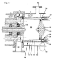
- FIG. 1 shows a centrifugal dryer on which the inventive method can be carried out.
- the centrifugal dryer has a drum 10 which comprises a drum shell 11 and a drum base 12 which is fixedly connected to a drive shaft 20 used for filling.
- the drum base 12 further has drum bottom openings 14.
- a metal filter 16 is arranged within the drum 10.
- the annular space 18 is divided in the illustrated embodiment into twelve sections, each having a trained as a slot drum bottom opening 14.
- the working area 60 in which the product is processed, ie centrifuged and dried, will. Opposite the drum base 12 of the work area 60 is closed by a baffle plate 40, which can be opened. When the baffle plate 40 is open, the product can be transferred from the working space 60 into the area 80 and removed.
- a drain 52 through which the liquid phase of the product can flow, and an outlet 54 are provided, through which gases introduced into the working area can escape.
- FIG. 2 shows a schematic frontal view of the drum 10.
- the direction of rotation of the drum 10 is in the present example in the clockwise direction.
- the vertex 70 of the drum 10 as well as a first weft nozzle 31 and a second weft nozzle 32 are also shown.
- the first weft nozzle 31 is in the so-called 6 o'clock position and the second weft nozzle 32 is in the so-called 7 o'clock position ,
- the first firing nozzle 31 is offset from the second firing nozzle 32 by about 30 °.
- further firing nozzles may be provided, such as the third firing nozzle 33, which is located at the eleven o'clock position.
- the firing nozzles inject a suitable fluid, which is preferably gaseous, into the working area 60 through the drum bottom openings formed as elongated holes 90 through the annular space 18 and the filter 16.
- the centrifugal dryer used should have a single-motor concept as a drive. This makes it possible to continuously approach all speeds between a standstill and a maximum speed of the drum.
- the centrifugal dryer on which the process according to the invention is carried out should have a suitable control system.
- the centrifuge dryer must be able to control the injections through the shot nozzles 30 in the millisecond range.
- the position of the drum 10 must be able to be detected in the minute range (based on the angular position).
- a play-free and rigid coupling between the drive shaft 20 and the motor is necessary. By a single engine concept, this can be suitably provided.
- FIG. 3 shows the grain size spectrum of a typical product that can be processed by the method according to the invention.
- the product has a fines content of about 20%.
- About 20% of the product has a grain size of 10 ⁇ m or less.
- the product shown is not to be considered as limiting the use of the method of the invention. Rather, the method of the invention provides improved centrifugation and drying in all types of products.
- a product suspension is first introduced into the working area 60 in a first step of filling through the drive shaft 20 designed as a filling shaft.
- the drum 10 rotates continuously during filling.
- the speed of the drum is chosen so that the forces in Radial direction are so high that forms a ring of the product suspension on the filter 16.
- a suitable fluid can be injected into the working space by means of the general shot nozzles designated 30.
- the shot nozzles 30 are moved close to the drum base, so that there is only a minimal gap between the nozzle head 38 and the drum base 12.
- the firing nozzles 30 are always fixed while the drum 10 is rotating.
- the firing nozzles can be made axially movable.
- a feed duct 34 is surrounded by a bellows 36 and the firing nozzles 30 can be moved axially by means of a suitable device.
- a suitable fluid is basically to understand such a fluid that does not cause any chemical reactions in the product and does not damage the product in any other way.
- the fluid used is usually gaseous.
- the firing nozzles 30 initially inject the fluid through the elongated holes in the annular space 18, from which the fluid moves through the filter 16 into the working space 60.
- the fluid exits the working space 60 at another location in the opposite direction again through the filter 16 and escapes through the drum bottom openings 14 and the outlet 54th
- a first nozzle 31 and a second nozzle 32 inject during a first revolution in the same slot 14 'a. During the next drum revolution they inject the fluid into the next, ie offset by one, slot 14 ", etc. This ensures that the product over the entire Drum circumference is whirled up. The whirling up thus always takes place when the corresponding drum section passes the range between 6 and 7 o'clock.
- an initially thin, solid-state ring forms on the filter.
- a suspension consisting of the liquid fraction and the remaining solids, continuously adding suspension to a maximum.
- the suspension can not build up into a stable ring.
- the suspension thereby forms a suspension lake within the solid ring.
- the shear forces are large enough that forms an approximately 1 mm thin suspension layer on the inside of the solid ring.
- the filling step is then transferred to the centrifuging step.
- the drum 10 rotates at a suitable speed during centrifuging, at a drum diameter of 400 mm, for example 150 rpm, or so fast that 5 g act on the cake, and the suspension is constantly loosened up by the injection of fluid by means of the firing nozzles 30. This prevents the smaller particle size of the product from being trapped between the larger particle size portions of the product and clogging the capillaries needed to complete the liquid phase. Also, the filter itself is not clogged by the fine product components, since it is regularly flowed through in the opposite direction of the fluid gas.
- the centrifuging step blends into the step of drying.
- the rotational speed of the drum 10 is about 150 rpm with a drum diameter of 400 mm during drying.
- the annular structure of the product cake is retained and the product cake does not collapse.
- the firing nozzles 30 now inject a hot drying gas into the working space 60.
- the hot drying gas must penetrate the product cake twice.
- a particularly high drying efficiency is achieved.
- the product cake is dried evenly from two sides. By constantly loosening the product cake over the In addition, there is no clumping of the product due to the entire circumference and the stationary maintenance of the ring shape of the product cake.
- the product By maintaining an annular cake throughout the drying process, the product itself acts as an additional filter which prevents the fines of the product from escaping through the filter 16.
- hot drying gas can also be introduced into the working chamber 60 through the drive shaft 20. This can additionally increase the drying speed of the product. By preventing drying cracks in the product by the continuous loosening, the drying gas in the working space 60 can not easily escape through the drying cracks, but completely passes through the product, thereby further increasing the drying efficiency.
- the step of drying is followed by a homogenization step.
- the drum speed is lowered in a drum with a diameter of 400 mm from 150 U / min to about 50 to 80 U / min or to a radial acceleration of less than 1 g.
- the product cake now collapses.
- the product now has the form of a fine powder which collects at the bottom of the drum 10 and is entrained by the drum 10 in the direction of the apex 70 of the drum 10. However, before reaching the apex 70, the product trickles down again in the direction of the low point of the drum 10. In this way mixing and homogenisation of the product is achieved, whereby after a short time the different grain sizes and residual moisture content are distributed evenly throughout the product.
- a gas can be injected into the working space 60, in addition to the product loosen. However, this is not absolutely necessary during the homogenization step.
- the dried product can be removed as a fine powder.
- the process according to the invention provides a shorter drying time for all types of products, ie also for those products which hitherto were considered to be non-problematic, due to the higher porosity of the product during processing.
- the inventive method is thus not on the example.
- FIG. 3 can advantageously be applied to all types of chemical and pharmaceutical products, as well as food and all kinds of centrifuges.
Landscapes
- Centrifugal Separators (AREA)
Applications Claiming Priority (2)
| Application Number | Priority Date | Filing Date | Title |
|---|---|---|---|
| DE102006009200A DE102006009200A1 (de) | 2006-02-22 | 2006-02-22 | Verfahren für den Betrieb einer Zentrifuge |
| EP07703132A EP1940554B1 (fr) | 2006-02-22 | 2007-01-30 | Procede d'utilisation d'une centrifugeuse |
Related Parent Applications (1)
| Application Number | Title | Priority Date | Filing Date |
|---|---|---|---|
| EP07703132A Division EP1940554B1 (fr) | 2006-02-22 | 2007-01-30 | Procede d'utilisation d'une centrifugeuse |
Publications (2)
| Publication Number | Publication Date |
|---|---|
| EP1958698A1 true EP1958698A1 (fr) | 2008-08-20 |
| EP1958698B1 EP1958698B1 (fr) | 2009-05-13 |
Family
ID=37963710
Family Applications (2)
| Application Number | Title | Priority Date | Filing Date |
|---|---|---|---|
| EP07703132A Active EP1940554B1 (fr) | 2006-02-22 | 2007-01-30 | Procede d'utilisation d'une centrifugeuse |
| EP08007829A Active EP1958698B1 (fr) | 2006-02-22 | 2007-01-30 | Procédé de fonctionnement d'une centrifugeuse |
Family Applications Before (1)
| Application Number | Title | Priority Date | Filing Date |
|---|---|---|---|
| EP07703132A Active EP1940554B1 (fr) | 2006-02-22 | 2007-01-30 | Procede d'utilisation d'une centrifugeuse |
Country Status (8)
| Country | Link |
|---|---|
| US (1) | US7972520B2 (fr) |
| EP (2) | EP1940554B1 (fr) |
| JP (1) | JP4971368B2 (fr) |
| KR (1) | KR101043513B1 (fr) |
| CN (1) | CN101370593B (fr) |
| AT (2) | ATE431191T1 (fr) |
| DE (3) | DE102006009200A1 (fr) |
| WO (1) | WO2007096044A2 (fr) |
Families Citing this family (5)
| Publication number | Priority date | Publication date | Assignee | Title |
|---|---|---|---|---|
| US8771160B2 (en) | 2008-01-31 | 2014-07-08 | F. P. Marangoni Inc. | Gas injection-aided centrifugal separation of entrained solids from a solution |
| AU2018390481A1 (en) * | 2017-12-19 | 2020-07-09 | Xeros Limited | Filter for a treatment apparatus |
| DE102019106842A1 (de) * | 2019-03-18 | 2020-09-24 | Bma Braunschweigische Maschinenbauanstalt Ag | Verfahren zum Regeln des Betriebes einer kontinuierlich oder periodisch arbeitenden Zentrifuge und Einrichtung zur Durchführung des Verfahrens |
| KR102504657B1 (ko) * | 2019-11-18 | 2023-02-27 | 주식회사 엘지화학 | 가압 원심 탈수기 |
| KR102646571B1 (ko) * | 2020-10-05 | 2024-03-11 | 주식회사 엘지화학 | 연속식 원심 탈수기 |
Citations (2)
| Publication number | Priority date | Publication date | Assignee | Title |
|---|---|---|---|---|
| EP0454045A2 (fr) * | 1990-04-26 | 1991-10-30 | Hans Joachim Dipl.-Ing. Titus | Appareil de séchage centrifuge |
| DE10245013A1 (de) * | 2002-09-20 | 2004-04-01 | Heinkel Aktiengesellschaft | Filterzentrifuge |
Family Cites Families (12)
| Publication number | Priority date | Publication date | Assignee | Title |
|---|---|---|---|---|
| JPS6174609A (ja) * | 1984-09-17 | 1986-04-16 | 李 正▲か▼ | 回転濾過装置を有する汚物凝縮脱水機 |
| DE4230261A1 (de) * | 1991-10-01 | 1993-04-08 | Krauss Maffei Ag | Diskontinuierlich arbeitende filterzentrifuge |
| US5300233A (en) * | 1993-02-09 | 1994-04-05 | Dorr-Oliver Incorporated | Process of displacement washing in a centrifuge filter |
| JP3313286B2 (ja) * | 1996-01-17 | 2002-08-12 | 株式会社松本機械製作所 | 遠心ろ過方法及び装置 |
| DE19646038C2 (de) | 1996-11-08 | 1998-08-06 | Heinkel Ind Zentrifugen | Stülpfilterzentrifuge |
| US6159360A (en) * | 1996-11-22 | 2000-12-12 | Heinkel Industriezentrifugen Gmbh & Co. | Invertible filter centrifuge including a solids drier |
| DE19648511C1 (de) * | 1996-11-22 | 1998-04-16 | Heinkel Ind Zentrifugen | Stülpfilterzentrifuge |
| FR2795497B1 (fr) * | 1999-06-24 | 2001-09-21 | Freeze Agro Ingenierie | Essoreuse a effet centrifuge pour produits en vrac et procede d'essorage |
| DE10115381A1 (de) * | 2001-03-28 | 2002-10-24 | Heinkel Ag | Stülpfilterzentrifuge |
| DE10311997A1 (de) * | 2003-03-19 | 2004-10-07 | Johannes Gerteis | Stülpfilterzentrifuge |
| JP4353925B2 (ja) * | 2005-07-13 | 2009-10-28 | 塩野義製薬株式会社 | 分離乾燥装置 |
| US20080149558A1 (en) * | 2006-12-21 | 2008-06-26 | Ferrum Ag | Centrifuge drum |
-
2006
- 2006-02-22 DE DE102006009200A patent/DE102006009200A1/de not_active Withdrawn
-
2007
- 2007-01-30 WO PCT/EP2007/000778 patent/WO2007096044A2/fr active Application Filing
- 2007-01-30 CN CN200780003065XA patent/CN101370593B/zh active Active
- 2007-01-30 DE DE502007000732T patent/DE502007000732D1/de active Active
- 2007-01-30 AT AT08007829T patent/ATE431191T1/de active
- 2007-01-30 US US12/223,540 patent/US7972520B2/en active Active
- 2007-01-30 EP EP07703132A patent/EP1940554B1/fr active Active
- 2007-01-30 DE DE502007000404T patent/DE502007000404D1/de active Active
- 2007-01-30 JP JP2008555657A patent/JP4971368B2/ja active Active
- 2007-01-30 EP EP08007829A patent/EP1958698B1/fr active Active
- 2007-01-30 AT AT07703132T patent/ATE421383T1/de not_active IP Right Cessation
- 2007-01-30 KR KR1020087023107A patent/KR101043513B1/ko active IP Right Grant
Patent Citations (2)
| Publication number | Priority date | Publication date | Assignee | Title |
|---|---|---|---|---|
| EP0454045A2 (fr) * | 1990-04-26 | 1991-10-30 | Hans Joachim Dipl.-Ing. Titus | Appareil de séchage centrifuge |
| DE10245013A1 (de) * | 2002-09-20 | 2004-04-01 | Heinkel Aktiengesellschaft | Filterzentrifuge |
Also Published As
| Publication number | Publication date |
|---|---|
| JP2009527348A (ja) | 2009-07-30 |
| DE102006009200A1 (de) | 2007-08-30 |
| ATE431191T1 (de) | 2009-05-15 |
| WO2007096044A2 (fr) | 2007-08-30 |
| EP1958698B1 (fr) | 2009-05-13 |
| US20090045147A1 (en) | 2009-02-19 |
| CN101370593A (zh) | 2009-02-18 |
| KR20080102226A (ko) | 2008-11-24 |
| DE502007000404D1 (de) | 2009-03-12 |
| WO2007096044A3 (fr) | 2007-11-08 |
| US7972520B2 (en) | 2011-07-05 |
| ATE421383T1 (de) | 2009-02-15 |
| EP1940554A2 (fr) | 2008-07-09 |
| CN101370593B (zh) | 2012-11-21 |
| KR101043513B1 (ko) | 2011-06-23 |
| JP4971368B2 (ja) | 2012-07-11 |
| EP1940554B1 (fr) | 2009-01-21 |
| DE502007000732D1 (de) | 2009-06-25 |
Similar Documents
| Publication | Publication Date | Title |
|---|---|---|
| EP0369149B1 (fr) | Broyeur malaxeur à boulets | |
| EP0737096B1 (fr) | Utilisation d'un melangeur pour concher | |
| DE3318793A1 (de) | Vorrichtung zum entfeuchten von schlamm | |
| EP1940554B1 (fr) | Procede d'utilisation d'une centrifugeuse | |
| DE1925001A1 (de) | Zentrifuge | |
| EP2348899A2 (fr) | Extrusion extractive d'un produit de tabac | |
| EP1468744A1 (fr) | Centrifugeuse à poussoir avec cone rotatif pour pre-accélerer le mélange | |
| WO1991006364A1 (fr) | Dispositif pour l'agitation de particules solides | |
| DE3301099C2 (fr) | ||
| EP2683487B1 (fr) | Broyeur à billes agité | |
| DE4315074A1 (de) | Verfahren und Vorrichtung zum Entwässern von Schlämmen | |
| DE915408C (de) | Verfahren zum Betrieb einer Muehle | |
| EP2332693A1 (fr) | Dispositif et procédé destinés à la production et l'application de glace sèche | |
| EP1280606A1 (fr) | Centrifugeuse a bol plein pour la separation de melanges de substances liquides et solides | |
| DE2834491A1 (de) | Siebzentrifuge mit gekruemmten siebtaschen | |
| DE1632291B1 (de) | Kontinuierlich arbeitende Siebzentrifuge | |
| EP1181103B1 (fr) | Centrifugeuse | |
| EP1468742A1 (fr) | Centrifugeuse à poussoir avec plusieur étages | |
| DE1909016A1 (de) | Vorrichtung zur Beschleunigung fliessfaehiger,insbesondere koerniger Substanzen | |
| EP1468743A1 (fr) | Centrifugeuse-pousseuse | |
| DE2930312A1 (de) | Siebzentrifuge | |
| DE2602095C2 (de) | Trommel für Schubzentrifugen | |
| DE1456798C (de) | Schleuderteller fur Schuttguter | |
| AT210846B (de) | Kontinuierlich arbeitende Zentrifuge mit konischem Siebkorb und senkrechter Antriebswelle, z. B. für Zuckersäfte | |
| DD227339B5 (de) | Ruehrwerksmuehle |
Legal Events
| Date | Code | Title | Description |
|---|---|---|---|
| PUAI | Public reference made under article 153(3) epc to a published international application that has entered the european phase |
Free format text: ORIGINAL CODE: 0009012 |
|
| AC | Divisional application: reference to earlier application |
Ref document number: 1940554 Country of ref document: EP Kind code of ref document: P |
|
| AK | Designated contracting states |
Kind code of ref document: A1 Designated state(s): AT BE BG CH CY CZ DE DK EE ES FI FR GB GR HU IE IS IT LI LT LU LV MC NL PL PT RO SE SI SK TR |
|
| AX | Request for extension of the european patent |
Extension state: AL BA HR MK RS |
|
| 17P | Request for examination filed |
Effective date: 20080808 |
|
| GRAP | Despatch of communication of intention to grant a patent |
Free format text: ORIGINAL CODE: EPIDOSNIGR1 |
|
| GRAS | Grant fee paid |
Free format text: ORIGINAL CODE: EPIDOSNIGR3 |
|
| GRAA | (expected) grant |
Free format text: ORIGINAL CODE: 0009210 |
|
| AKX | Designation fees paid |
Designated state(s): AT BE BG CH CY CZ DE DK EE ES FI FR GB GR HU IE IS IT LI LT LU LV MC NL PL PT RO SE SI SK TR |
|
| AC | Divisional application: reference to earlier application |
Ref document number: 1940554 Country of ref document: EP Kind code of ref document: P |
|
| AK | Designated contracting states |
Kind code of ref document: B1 Designated state(s): AT BE BG CH CY CZ DE DK EE ES FI FR GB GR HU IE IS IT LI LT LU LV MC NL PL PT RO SE SI SK TR |
|
| REG | Reference to a national code |
Ref country code: GB Ref legal event code: FG4D Free format text: NOT ENGLISH |
|
| REG | Reference to a national code |
Ref country code: CH Ref legal event code: EP |
|
| REG | Reference to a national code |
Ref country code: IE Ref legal event code: FG4D |
|
| REG | Reference to a national code |
Ref country code: CH Ref legal event code: NV Representative=s name: BRAUNPAT BRAUN EDER AG |
|
| REF | Corresponds to: |
Ref document number: 502007000732 Country of ref document: DE Date of ref document: 20090625 Kind code of ref document: P |
|
| PG25 | Lapsed in a contracting state [announced via postgrant information from national office to epo] |
Ref country code: PT Free format text: LAPSE BECAUSE OF FAILURE TO SUBMIT A TRANSLATION OF THE DESCRIPTION OR TO PAY THE FEE WITHIN THE PRESCRIBED TIME-LIMIT Effective date: 20090913 Ref country code: FI Free format text: LAPSE BECAUSE OF FAILURE TO SUBMIT A TRANSLATION OF THE DESCRIPTION OR TO PAY THE FEE WITHIN THE PRESCRIBED TIME-LIMIT Effective date: 20090513 Ref country code: LT Free format text: LAPSE BECAUSE OF FAILURE TO SUBMIT A TRANSLATION OF THE DESCRIPTION OR TO PAY THE FEE WITHIN THE PRESCRIBED TIME-LIMIT Effective date: 20090513 Ref country code: ES Free format text: LAPSE BECAUSE OF FAILURE TO SUBMIT A TRANSLATION OF THE DESCRIPTION OR TO PAY THE FEE WITHIN THE PRESCRIBED TIME-LIMIT Effective date: 20090824 |
|
| NLV1 | Nl: lapsed or annulled due to failure to fulfill the requirements of art. 29p and 29m of the patents act | ||
| PG25 | Lapsed in a contracting state [announced via postgrant information from national office to epo] |
Ref country code: NL Free format text: LAPSE BECAUSE OF FAILURE TO SUBMIT A TRANSLATION OF THE DESCRIPTION OR TO PAY THE FEE WITHIN THE PRESCRIBED TIME-LIMIT Effective date: 20090513 Ref country code: IS Free format text: LAPSE BECAUSE OF FAILURE TO SUBMIT A TRANSLATION OF THE DESCRIPTION OR TO PAY THE FEE WITHIN THE PRESCRIBED TIME-LIMIT Effective date: 20090913 Ref country code: SI Free format text: LAPSE BECAUSE OF FAILURE TO SUBMIT A TRANSLATION OF THE DESCRIPTION OR TO PAY THE FEE WITHIN THE PRESCRIBED TIME-LIMIT Effective date: 20090513 Ref country code: LV Free format text: LAPSE BECAUSE OF FAILURE TO SUBMIT A TRANSLATION OF THE DESCRIPTION OR TO PAY THE FEE WITHIN THE PRESCRIBED TIME-LIMIT Effective date: 20090513 Ref country code: SE Free format text: LAPSE BECAUSE OF FAILURE TO SUBMIT A TRANSLATION OF THE DESCRIPTION OR TO PAY THE FEE WITHIN THE PRESCRIBED TIME-LIMIT Effective date: 20090813 Ref country code: PL Free format text: LAPSE BECAUSE OF FAILURE TO SUBMIT A TRANSLATION OF THE DESCRIPTION OR TO PAY THE FEE WITHIN THE PRESCRIBED TIME-LIMIT Effective date: 20090513 |
|
| PG25 | Lapsed in a contracting state [announced via postgrant information from national office to epo] |
Ref country code: DK Free format text: LAPSE BECAUSE OF FAILURE TO SUBMIT A TRANSLATION OF THE DESCRIPTION OR TO PAY THE FEE WITHIN THE PRESCRIBED TIME-LIMIT Effective date: 20090513 Ref country code: CZ Free format text: LAPSE BECAUSE OF FAILURE TO SUBMIT A TRANSLATION OF THE DESCRIPTION OR TO PAY THE FEE WITHIN THE PRESCRIBED TIME-LIMIT Effective date: 20090513 Ref country code: EE Free format text: LAPSE BECAUSE OF FAILURE TO SUBMIT A TRANSLATION OF THE DESCRIPTION OR TO PAY THE FEE WITHIN THE PRESCRIBED TIME-LIMIT Effective date: 20090513 |
|
| PG25 | Lapsed in a contracting state [announced via postgrant information from national office to epo] |
Ref country code: SK Free format text: LAPSE BECAUSE OF FAILURE TO SUBMIT A TRANSLATION OF THE DESCRIPTION OR TO PAY THE FEE WITHIN THE PRESCRIBED TIME-LIMIT Effective date: 20090513 |
|
| PLBE | No opposition filed within time limit |
Free format text: ORIGINAL CODE: 0009261 |
|
| STAA | Information on the status of an ep patent application or granted ep patent |
Free format text: STATUS: NO OPPOSITION FILED WITHIN TIME LIMIT |
|
| PG25 | Lapsed in a contracting state [announced via postgrant information from national office to epo] |
Ref country code: BG Free format text: LAPSE BECAUSE OF FAILURE TO SUBMIT A TRANSLATION OF THE DESCRIPTION OR TO PAY THE FEE WITHIN THE PRESCRIBED TIME-LIMIT Effective date: 20090813 |
|
| 26N | No opposition filed |
Effective date: 20100216 |
|
| PG25 | Lapsed in a contracting state [announced via postgrant information from national office to epo] |
Ref country code: MC Free format text: LAPSE BECAUSE OF NON-PAYMENT OF DUE FEES Effective date: 20100131 |
|
| PG25 | Lapsed in a contracting state [announced via postgrant information from national office to epo] |
Ref country code: GR Free format text: LAPSE BECAUSE OF FAILURE TO SUBMIT A TRANSLATION OF THE DESCRIPTION OR TO PAY THE FEE WITHIN THE PRESCRIBED TIME-LIMIT Effective date: 20090814 |
|
| PGRI | Patent reinstated in contracting state [announced from national office to epo] |
Ref country code: IT Effective date: 20110501 |
|
| PGRI | Patent reinstated in contracting state [announced from national office to epo] |
Ref country code: IT Effective date: 20110501 |
|
| PG25 | Lapsed in a contracting state [announced via postgrant information from national office to epo] |
Ref country code: CY Free format text: LAPSE BECAUSE OF FAILURE TO SUBMIT A TRANSLATION OF THE DESCRIPTION OR TO PAY THE FEE WITHIN THE PRESCRIBED TIME-LIMIT Effective date: 20090513 |
|
| PG25 | Lapsed in a contracting state [announced via postgrant information from national office to epo] |
Ref country code: HU Free format text: LAPSE BECAUSE OF FAILURE TO SUBMIT A TRANSLATION OF THE DESCRIPTION OR TO PAY THE FEE WITHIN THE PRESCRIBED TIME-LIMIT Effective date: 20091114 Ref country code: LU Free format text: LAPSE BECAUSE OF NON-PAYMENT OF DUE FEES Effective date: 20100130 |
|
| PG25 | Lapsed in a contracting state [announced via postgrant information from national office to epo] |
Ref country code: TR Free format text: LAPSE BECAUSE OF FAILURE TO SUBMIT A TRANSLATION OF THE DESCRIPTION OR TO PAY THE FEE WITHIN THE PRESCRIBED TIME-LIMIT Effective date: 20090513 |
|
| REG | Reference to a national code |
Ref country code: AT Ref legal event code: MM01 Ref document number: 431191 Country of ref document: AT Kind code of ref document: T Effective date: 20120130 |
|
| PG25 | Lapsed in a contracting state [announced via postgrant information from national office to epo] |
Ref country code: AT Free format text: LAPSE BECAUSE OF NON-PAYMENT OF DUE FEES Effective date: 20120130 |
|
| PG25 | Lapsed in a contracting state [announced via postgrant information from national office to epo] |
Ref country code: RO Free format text: LAPSE BECAUSE OF FAILURE TO SUBMIT A TRANSLATION OF THE DESCRIPTION OR TO PAY THE FEE WITHIN THE PRESCRIBED TIME-LIMIT Effective date: 20090513 |
|
| REG | Reference to a national code |
Ref country code: FR Ref legal event code: PLFP Year of fee payment: 10 |
|
| REG | Reference to a national code |
Ref country code: DE Ref legal event code: R082 Ref document number: 502007000732 Country of ref document: DE Representative=s name: GLAWE DELFS MOLL PARTNERSCHAFT MBB VON PATENT-, DE |
|
| REG | Reference to a national code |
Ref country code: FR Ref legal event code: PLFP Year of fee payment: 11 |
|
| REG | Reference to a national code |
Ref country code: FR Ref legal event code: PLFP Year of fee payment: 12 |
|
| REG | Reference to a national code |
Ref country code: CH Ref legal event code: PCAR Free format text: NEW ADDRESS: HOLEESTRASSE 87, 4054 BASEL (CH) |
|
| PGFP | Annual fee paid to national office [announced via postgrant information from national office to epo] |
Ref country code: IE Payment date: 20240118 Year of fee payment: 18 |
|
| PGFP | Annual fee paid to national office [announced via postgrant information from national office to epo] |
Ref country code: DE Payment date: 20240119 Year of fee payment: 18 Ref country code: GB Payment date: 20240117 Year of fee payment: 18 Ref country code: CH Payment date: 20240202 Year of fee payment: 18 |
|
| PGFP | Annual fee paid to national office [announced via postgrant information from national office to epo] |
Ref country code: IT Payment date: 20240131 Year of fee payment: 18 Ref country code: FR Payment date: 20240124 Year of fee payment: 18 Ref country code: BE Payment date: 20240122 Year of fee payment: 18 |