EP1956201A2 - Einstellbare Ventiltriebsvorrichtung eines Motors und Montageverfahren dafür - Google Patents
Einstellbare Ventiltriebsvorrichtung eines Motors und Montageverfahren dafür Download PDFInfo
- Publication number
- EP1956201A2 EP1956201A2 EP08001956A EP08001956A EP1956201A2 EP 1956201 A2 EP1956201 A2 EP 1956201A2 EP 08001956 A EP08001956 A EP 08001956A EP 08001956 A EP08001956 A EP 08001956A EP 1956201 A2 EP1956201 A2 EP 1956201A2
- Authority
- EP
- European Patent Office
- Prior art keywords
- pin
- cam
- split body
- support portion
- connection pin
- Prior art date
- Legal status (The legal status is an assumption and is not a legal conclusion. Google has not performed a legal analysis and makes no representation as to the accuracy of the status listed.)
- Granted
Links
- 238000000034 method Methods 0.000 title claims description 7
- 230000007246 mechanism Effects 0.000 claims description 16
- 230000008859 change Effects 0.000 claims description 9
- 230000008878 coupling Effects 0.000 claims description 4
- 238000010168 coupling process Methods 0.000 claims description 4
- 238000005859 coupling reaction Methods 0.000 claims description 4
- 238000000926 separation method Methods 0.000 abstract description 6
- 230000002093 peripheral effect Effects 0.000 description 5
- 125000006850 spacer group Chemical group 0.000 description 5
- 238000006073 displacement reaction Methods 0.000 description 2
- 230000001133 acceleration Effects 0.000 description 1
- 238000010276 construction Methods 0.000 description 1
- 230000003111 delayed effect Effects 0.000 description 1
- 230000001419 dependent effect Effects 0.000 description 1
- 238000005516 engineering process Methods 0.000 description 1
- 238000003780 insertion Methods 0.000 description 1
- 230000037431 insertion Effects 0.000 description 1
- KJFBVJALEQWJBS-XUXIUFHCSA-N maribavir Chemical compound CC(C)NC1=NC2=CC(Cl)=C(Cl)C=C2N1[C@H]1O[C@@H](CO)[C@H](O)[C@@H]1O KJFBVJALEQWJBS-XUXIUFHCSA-N 0.000 description 1
- 238000012986 modification Methods 0.000 description 1
- 230000004048 modification Effects 0.000 description 1
- 230000000149 penetrating effect Effects 0.000 description 1
- 238000005086 pumping Methods 0.000 description 1
- 230000000630 rising effect Effects 0.000 description 1
- 230000001052 transient effect Effects 0.000 description 1
Images




Classifications
-
- F—MECHANICAL ENGINEERING; LIGHTING; HEATING; WEAPONS; BLASTING
- F01—MACHINES OR ENGINES IN GENERAL; ENGINE PLANTS IN GENERAL; STEAM ENGINES
- F01L—CYCLICALLY OPERATING VALVES FOR MACHINES OR ENGINES
- F01L13/00—Modifications of valve-gear to facilitate reversing, braking, starting, changing compression ratio, or other specific operations
- F01L13/0015—Modifications of valve-gear to facilitate reversing, braking, starting, changing compression ratio, or other specific operations for optimising engine performances by modifying valve lift according to various working parameters, e.g. rotational speed, load, torque
- F01L13/0063—Modifications of valve-gear to facilitate reversing, braking, starting, changing compression ratio, or other specific operations for optimising engine performances by modifying valve lift according to various working parameters, e.g. rotational speed, load, torque by modification of cam contact point by displacing an intermediate lever or wedge-shaped intermediate element, e.g. Tourtelot
-
- Y—GENERAL TAGGING OF NEW TECHNOLOGICAL DEVELOPMENTS; GENERAL TAGGING OF CROSS-SECTIONAL TECHNOLOGIES SPANNING OVER SEVERAL SECTIONS OF THE IPC; TECHNICAL SUBJECTS COVERED BY FORMER USPC CROSS-REFERENCE ART COLLECTIONS [XRACs] AND DIGESTS
- Y10—TECHNICAL SUBJECTS COVERED BY FORMER USPC
- Y10T—TECHNICAL SUBJECTS COVERED BY FORMER US CLASSIFICATION
- Y10T74/00—Machine element or mechanism
- Y10T74/20—Control lever and linkage systems
- Y10T74/20576—Elements
- Y10T74/20882—Rocker arms
-
- Y—GENERAL TAGGING OF NEW TECHNOLOGICAL DEVELOPMENTS; GENERAL TAGGING OF CROSS-SECTIONAL TECHNOLOGIES SPANNING OVER SEVERAL SECTIONS OF THE IPC; TECHNICAL SUBJECTS COVERED BY FORMER USPC CROSS-REFERENCE ART COLLECTIONS [XRACs] AND DIGESTS
- Y10—TECHNICAL SUBJECTS COVERED BY FORMER USPC
- Y10T—TECHNICAL SUBJECTS COVERED BY FORMER US CLASSIFICATION
- Y10T74/00—Machine element or mechanism
- Y10T74/21—Elements
- Y10T74/2101—Cams
- Y10T74/2107—Follower
Definitions
- the present invention relates to an adjustable valve drive device of an engine and to a method of mounting it, and in particular relates to a technology for properly reducing a stress acting in a direction of separation of first and second split bodies that constitute a rocker cam.
- a valve timing or a valve lift of intake and exhaust valves of an engine are changed according to an engine operation state.
- An example of such an adjustable valve drive device is disclosed in Japanese Patent Laid-Open Publication No. 2004-301058 , in which an outer ring is provided so as to fit onto an eccentric cam that is provided at a cam shaft, a rocker cam operative to lift (drive) an intake valve is supported at the cam shaft so as to be rocking, the displacement of the outer ring according to rotation of the eccentric cam is transmittable to the rocker cam via a link mechanism that comprises a control link coupled to the outer ring and a link coupled to the rocker cam, and the distance between a rocker support point of the control link and an axial center of the rocker cam is changeable according to the engine operation state.
- the valve opening start timing can be advanced and the valve lift can be increased by reducing the above-described distance at an engine high-speed and high-load state, while the valve opening start timing can be delayed and the valve lift can be reduced by increasing the above-described distance at an engine low-speed and low-load state.
- the rocker cam for the control of the valve timing of the engine needs to be replaced with a new one when its cam profile face has come to wear off in order to maintain the proper performance.
- the rocker cam is comprised of a first split body with a cam profile face and a second split body without a cam profile, which are joined to one another by a fastening bolt.
- Increasing of a fastening force of the above-descried fastening bolt or thickness of the split bodies for solving the above-described concern may cause another issue of a large size or a heavy weight of the rocker cam instead.
- the weight of the rocker cam be as light as possible because of the rocker cam's repeated rocking movement.
- the present invention has been devised in view of the above-described matters, and an object of the present invention is to provide an adjustable valve drive device of an engine and a mounting method therefor that can properly reduce a separation force that acts on the first and second split bodies of the rocker cam during its repeated rocking movement, without improperly increasing its rigidity.
- an adjustable valve drive device of an engine comprising a drive shaft provided in parallel to a crank shaft of the engine, a rocker cam operative to drive at least one valve, the rocker cam being supported at the drive shaft so as to be rocking, and a link mechanism coupled to a connection pin that is attached to the rocker cam, the connection pin having a pin axis that is provided so as to extend substantially in parallel to the drive shaft, the link mechanism being configured to change a valve lift characteristic by controlling a rocking range of the rocker cam, particularly according to an engine operation state
- the rocker cam comprises a first split body with a cam profile face and a second split body without a cam profile, which are joined to one another by at least one fastening bolt with a joint split face thereof that is formed so as to substantially contain (or to be arranged in correspondence with) an axial line of the drive shaft thereon, the first split body having a first pin support portion that supports one end portion of the connection pin, the second split body having a second pin
- connection pin for connection of the link mechanism controlling the rocking range of the rocker cam is supported at the first and second pin support portions at or near both end portions so as to extend between the first pin support portion of the first split body and the second pin support portion of the second split body, the stress that acts on the first and second split bodies in the separation direction during the valve drive operation can be reduced properly. Namely, the stress can be restrained from concentrating on only one of the split bodies, with the support of the connection pin at the both split bodies. Further, since there may be no need for improperly increasing the rigidity of the rocker cam by increasing its thickness or the like, the rocker cam can be made properly compact.
- the first split body has an extension portion at one end side thereof in an axial direction thereof, the extension portion being configured to extend outward from the second pin support portion of the second split body in the axial direction and preferably to have the first pin support portion facing the second pin support portion at a tip portion thereof, and/or the link mechanism preferably is disposed via the connection pin on one end side of the rocker cam in an axial direction of the rocker cam.
- connection pin has an base-end shaft portion with a screw thread and a tip-end shaft portion with a smaller diameter than the base-end shaft portion, either one of the first and second support pin portions has a hole which the tip-end shaft portion of the connection pin at least partly fits in and the other has a screw hole which the screw thread of the base-end shaft portion is at least partly screwed into.
- connection pin preferably is assembled, by being at least partly inserted from a side of the other of the first and second support pin portions with the screw hole through the screw hole, so that the tip-end shaft portion of the connection pin at least partly fits in the hole and the screw thread of the base-end shaft portion is screwed into the screw hole, whereby the connection pin can be supported at the first and second pin support portions at or near both end portions thereof.
- the rocker cam comprises cam portions, wherein on the cam profile face of the cam portions are formed a base circle area, where its radius of curvature is the same, from a cam nose area, where its radius of curvature becomes greater.
- said first split body has an extension portion at one end side thereof in an axial direction thereof, the extension portion being configured to extend outward from said second pin support portion of the second split body in the axial direction.
- said extension portion has said first pin support portion facing the second pin support portion at a tip portion thereof and/or wherein said link mechanism is disposed via said connection pin on one end side of the rocker cam in an axial direction of the rocker cam.
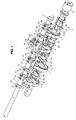
- FIG. 1 is a perspective view of an adjustable valve drive device according to an embodiment of the present invention.
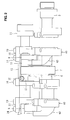
- FIG. 2 is a view of the adjustable valve drive device, when viewed in a direction of A.
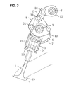
- FIG. 3 is a sectional view showing a state of a non-valve lift at a small lift control.
- FIG. 4 is a sectional view showing a state of a peak-valve lift at the small lift control.
- FIG. 5 is a sectional view showing a state of a non-valve lift at a large lift control.
- FIG. 6 is a sectional view showing a state of a peak-valve lift at the large lift control.
- FIG. 7 is a perspective view of a rocker cam.
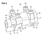
- FIG. 8 is a perspective view of the rocker cam, when viewed from a different angle.
- FIG. 9 is an explanatory plan view of assembling of a connection pin to the rocker cam.
- FIG. 10 is a perspective view of a first split body.
- FIG. 11 is a perspective view of a second split body.
- FIG. 12 is a side view of the rocker cam, when viewed in an axial direction.
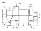
- FIG. 13 is an elevation view of the rocker cam.
- FIG. 1 is a perspective view of an adjustable valve drive device according to the present embodiment of the present invention.
- FIG. 2 is a view of the adjustable valve drive device, when viewed in a direction of A.
- An engine is particularly a four-valve preferably double-overhead cam type of engine that is equipped with two intake valves 1 (see FIG. 3 ) and two exhaust valves (not illustrated) for each cylinder as shown in FIGS. 1 and 2 .
- a reference character 3 denotes a cam shaft (drive shaft) that rotates synchronously with a crank shaft of the engine.
- the intake valve 1 is driven by a rocker cam 40 that is supported at the cam shaft 3 so as to be rocking.
- a valve lift and/or a valve timing of the intake valve are changeable according to an engine operation state.
- a plurality of eccentric cams 6 are integrally or unitarily formed with the cam shaft 3 in such a manner that the eccentric cams 6 are located in an axial direction with a specified (predetermined or predeterminable) distance therebetween.
- an outer ring 7 so as to fit onto the eccentric cam 6.
- the outer ring 7 and the rocker cam 40 are interconnected by a (preferably single) connection link 8 (as a preferred link mechanism).
- the rocker cam 40 is supported at the cam shaft 3 so as to be rocking around or move or reciprocate with respect to the cam shaft 3.
- a cylindrical portion 48 of the rocker cam 40 may be supported at a cylinder head or a cam carrier of the engine via a journal member, which are not illustrated here. This construction is preferable for a smooth rocking movement and a stable support of the rocker cam 40.
- a rotational shaft 11 is provided in parallel to the cam shaft 3. On the rotational shaft 11 are provided a plurality of control arms 12 so as to be located in an axial direction with a specified (predetermined or predeterminable) distance therebetween.
- One or more, preferably a plurality of stud bolts 17 are fixed to the rotational shaft 11 in such a manner that preferably each one end thereof is screwed into a screw hole formed at the shaft 11 and the other end thereof extends outward substantially in a radial direction of the shaft 11 through a through hole 12a formed at the control arm 12.
- Each stud bolt 17 is disposed at or near an one end of the control arm 12 (at a right-side end in FIG. 1 ).
- the above-described through hole 12a of the control arm 12 preferably is of an oval or elongated shape having its longer axis extending substantially in a circumferential direction of the arm 12, and one or more, preferably a pair of spacers 18, 18 is placed between the stud bolt 17 and the through hole 12a.
- these spacers 18 with a suitable size are applied after a relative angle of the control arm 12 to the rotational shaft 11 has been properly adjusted.
- An upper or distal end portion of the spacer 18 projects upward or outward beyond an outer face of the control arm 12.
- a washer 16 that has an inner peripheral surface, which preferably has substantially the same radius of curvature as an outer peripheral surface of the control arm 12 does, is put over the control arm 12.
- At the inner peripheral surface of the washer 16 is formed at least one groove 16a that preferably has an oval or elongated shape that substantially corresponds to the shape of the above-described through hole 12a of the control arm 12.
- the upper end portion of the spacer 18 is located so as to at least partly fit into the groove 16a, and the stud bolt 17 projecting upward through the through hole 16b of the washer 16 is fastened with a fastening nut 19.
- FIG. 1 also shows a single washer 16 in its upside-down state where it is removed from the control arm 12 just for explanation.
- the washer 16 is also fastened with a fastening bolt 14 that is disposed away from the fastening nut 19 preferably with a specified (predetermined or predeterminable) distance in the axial direction.
- a tip portion of the fastening bolt 14 penetrates the control arm 12 and is fastened to the rotational shaft 11.
- the control arm 12 is fastened to the rotational shaft 11.
- a washer 15 that has an inner peripheral surface, which preferably has substantially the same radius of curvature as the outer peripheral surface of the control arm 12 does, is fastened to the other end of the control arm 12 (a left-side end in FIG. 1 ) with the fastening bolt 14.
- a tip portion of the fastening bolt 14 penetrates the control arm 12 and is fastened to the rotational shaft 11. Thereby, the control arm 12 is fastened to the rotational shaft 11.
- control arm 12 and the outer ring 7 are interconnected by a control link 13, which controls the displacement of the outer ring 7 according to the rotation of the above-described eccentric cam 6 so that the rocker cam 40 can be rocking.
- the rotational shaft 11 is configured to be rotated by a motor, not illustrated, according to the engine operation state and thereby to rotate the control arm 12 so as to change the position of the control link 13 and thereby to change the valve lift and/or timing of the intake valve 1.
- the control arm 12 is controlled so that the valve lift becomes greater as the engine load becomes greater.
- a direct drive type of tappet 21 is provided at an upper or distal end of a stem of the intake valve 1 so that the rocker cam 40 contacts or interacts with the tappet 21.
- the intake valve 1 is generally biased by a valve spring 24 (as a preferred biasing member) provided between a retainer 22 provided in the tappet 21 and a retainer 23 provided at the cylinder in a direction of closing an intake port 25.
- connection link 8 is pivotally coupled to the rocker cam 40 via a connection pin 31 at its one end.
- the control link 13 is pivotally coupled to the tip of the control arm 12 via a connection pin 32 at its one end.
- connection link 8 and the control link 13 are linked via the outer ring 7.
- both the other ends of the connection link 8 and the control link 13 are pivotally and/or substantially coaxially coupled to a projection portion of the outer ring 7, which projects outward, via a connection pin 33.
- the connection pins 31- 33 extend in parallel to the cam shaft 3.
- the rotational direction of the cam shaft 3 (eccentric cam 6) is set to be clockwise in FIG. 3 .
- connection pin 33 for coupling the outer ring 7 to the connection link 8 is disposed above the cam shaft 3, and the rotational shaft 11 of the control arm 12 is disposed beside (or adjacent to or radially shifted with respect to) the coupling point.
- the connection pin 32 at the tip of the control arm 12 is or defines a rotational center of the control link 13. As shown in FIG. 3 , the connection pin 32 is moved upward and positioned above the can shaft 3 according to the rotation or pivotal movement or the rotational position of the control arm 12, which provides a small-lift control state.
- the position of the outer ring 7 is changeable according to the rotation of the eccentric cam 6, and the rocker cam 40 is rocking between a non-valve lift state (or small-valve lift state) of the intake valve 1 shown in FIG. 3 and a large lift state of the intake valve 1 shown in FIG. 4 (the rocker cam 40 pushes down greatly the valve 1 via the direct-drive type of tappet 21).
- FIG. 5 is a sectional view showing a large-lift control state. As shown in FIG. 5 , when the connection pin 32 is moved downward or closer to the cam shaft 3 according to the rotation of the control arm 12, the large-lift control state is provided.
- the rocker cam 40 coupled to the outer ring 7 via the connection link 8 is rocking between the non-valve lift state of the intake valve 1 shown in FIG. 5 and a large lift state of the intake valve 1 shown in FIG. 6 (the rocker cam 40 pushes down greatly the valve 1 via the direct-drive type of tappet 21 ).
- a base circular face of the rocker cam 40 contacts the tappet 21, so the valve lift is small or preferably zero (the intake valve 1 is closed).
- a tip end of the cam face of the rocker cam 40 contacts the tappet 21, so the valve lift becomes large or peak (the intake valve 1 is open).
- a first portion of the rocker cam 40 contacts the tappet 21, so the valve lift is zero or small while in the state shown in FIG. 6 , a second portion of the rocker cam 40 being at a radial distance from the camshaft 3 larger than that of the first portion contacts the tappet 21, so the valve lift becomes peak or large.
- connection link 8 and the control link 13 are linked via the outer ring 7. Accordingly, the valve lift controlled by the rocker cam 40 can be changed properly by changing the position of the control link 13 with the control arm 12, thereby particularly being in a position of providing an appropriate amount of intake air according to the engine operation state with simply adjusting the valve lift.
- a pumping loss can be properly reduced without an accelerator valve, and an intake efficiency at the large-lift control can be improved.
- FIG. 7 is a perspective view of the rocker cam.
- FIG. 8 is a perspective view of the rocker cam, when viewed from an opposite direction to that in FIG. 7 .
- the rocker cam 40 comprises one or more, preferably a pair of cam portions 47, 47 that drives the one or more, preferably two intake valves 1, 1 (see FIG. 3 ) and the cylindrical portion 48 that interconnects the both cam portions 47, 47.
- the rocker cam 40 is comprised of a first split body 41 with a cam profile face and a second split body 45 without a cam profile, which are joined to one another preferably by one or more fastening bolts 44 with a joint split face that is formed so as to preferably contain (or to be arranged in correspondence with) the axial line of the cam shaft 3.
- a through hole 49 is formed so as to extend in the axial direction at the cam portions 47, 47 and the cylindrical portion 48 of the rocker cam 40.
- the cam shaft 3 is provided so as to be at least partly inserted into this through hole 49.
- a base circular face (base circle area or first portion), where its radius of curvature is the same, from a cam face (cam nose area or second portion), where its radius of curvature becomes greater (see FIG. 12 ).
- the first split body 41 has an extension portion 43 at its one end side in its axial direction.
- the extension portion 43 extends outward from the second split body 45 substantially in the axial direction and has a first pin support portion 42 that supports one end portion of the connection pin 31 coupled to the connection pin 8.
- the second split body 45 has a second pin support portion 46 that supports the other end portion of the connection pin 31, substantially facing the first pin support portion 42.
- FIG. 9 is an explanatory plan view of assembling of the connection pin to the rocker cam.
- the connection pin comprises, as shown in FIG. 9 , a head portion 31 a, a base-end shaft portion 31b that has a diameter smaller than that of the head portion 31a and/or a screw thread, a connecting shaft portion 31c that has a diameter smaller than that of the base-end shaft portion 31b and becomes a rotational center of the connection link 8, and a tip-end shaft portion 31d that has a diameter smaller than that of the connecting shaft portion 31c .
- the above-described first pin support portion 42 has a screw hole 42a which the screw thread of the base-end shat portion 31b is at least partly screwed into, and a hole 42b which the head portion 31a at least partly fits in.
- These holes 42a, 42b are formed substantially in parallel to an axial direction of the through hole 49 of the rocker cam 40.
- the hole 42b has a diameter larger than that of the screw hole 42a, and it is formed on an insertion side of the connection pin 31 (on the left side in FIG. 9 ).
- the above-described second pin support portion 46 has a hole 46a that is formed substantially coaxially with the screw hole 42a of the first pin support portion 42 and in which the tip-end shaft portion 31d of the connection pin 31 at least partly fits, and a hole 46b that has a diameter smaller than that of the hole 46a.
- connection pin 31 is assembled in such a manner that it is at least partly inserted into the hole 42b and the screw hole 42a of the first pin support portion 42, its tip-end shaft portion 31d at least partly fits in the hole 46a of the second pin support portion 46, and the screw thread of the base-end shaft portion 31b is at least partly screwed into the screw hole 42a.
- the connection pin 31 is supported at the first and second pin support portions 42, 46 at its both end portions.
- connection pin 31 is disposed on one side of the rocker cam 40 in the axial direction of the rocker arm 40, the connection link 8 that is coupled to the rocker cam 40 via the connection pin 31 is likewise disposed on one side of the rocker cam 40 (on the left side in FIG. 1 ).
- FIG. 10 is a perspective view showing the constitution of the split face of the first split body.
- FIG. 11 is a perspective view showing the constitution of the split face of the second split body.
- FIG. 12 is a side view of the rocker cam, when viewed in the axial direction.
- the respective split faces of the first and second split bodies 41, 45 preferably have a difference in level in the radial direction.
- An inner-side portion of the split face forms split base faces 55 that substantially contain the axial line of the cam shaft 3 thereon.
- projection portions 56 At an outer-side portion of the split face of the first split body 41 are provided projection portions 56 that project from the split base face 55. This projection portion 56 is formed at a longitudinally-entire part of the pair of cam portions 47, 47 and the cylindrical portion 48.
- recesses portions 57 that preferably are dented from the split base face 5 so as to substantially correspond to the projection portions 56.
- the first and second split bodies 41, 45 are integrally fastened with the one or more fastening bolts 44 as shown in FIGS. 12 and 13 .
- the second split body 45 has one or more through holes 51 that allow shaft portions of the fastening bolts 44 to be at least partly inserted therein.
- the first split body 41 has one or more screw holes 52 that are formed substantially coaxially with the through holes 51 and in which screw threads of the fastening bolts 44 are screwed.
- the screw holes 52 of the first split body 41 are formed at one or more locations (e.g. four points) where the cam portions 47 are located in the axial direction (see FIG. 10 ).
- the screw holes 52 which are formed on the side of the cam face with the greater radius of curvature (cam nose area or second portion), have lower holes 53 preferably having a closed bottom, not penetrating or reaching the cam nose area (see FIG. 12 ).
- the screw holes 52 which are formed on the side of the base circular face with the substantially same radius of curvature (base circle area or first portion), have lower holes 54 that are provided so as not to penetrate or reach the base circle area and/or to open to a specified area that is located at an angle different from 0° or 180°, preferably substantially perpendicularly to the axial line of the screw hole 52 and/or outside the cam profile face (see FIG. 12 ). Opening of each of the lower holes 54 preferably is of an oval shape having its longer axis extending in the axial direction as shown in FIG. 13 .
- connection pin 31 for connection of the connection link 8 controlling the rocking range of the rocker cam 40 is supported at the first and second pin support portions 42, 46 at or near the both end portions so as to extend between the first pin support portion 42 of the first split body 41 and the second pin support portion 46 of the second split body 45, the stress that acts on the first and second split bodies 41, 45 in the separation direction during the valve drive operation can be reduced properly. Further, since there may be no need for improperly increasing the rigidity of the rocker cam 40 by increasing its thickness or the like, the rocker cam 40 can be made properly compact.
- a rocker cam 40 is comprised of a first split body 41 and a second split body 45, which are joined with a joint split face that contains an axial line of a cam shaft 3.
- the first split body 41 has a first pin support portion 42 that supports one end portion of the connection pin 31, and the second split body 45 has a second pin support portion 46 that is located so as to face the first pin support portion 42 and supports the other end portion of the connection pin 31.
- the connection pin 31 is supported at the first and second pin support portions 42, 46 at its both end portions. Accordingly, a separation force that acts on the first and second split bodies of the rocker cam during its repeated rocking movement can be reduced without improperly increasing its rigidity.
- the adjustable valve device according to the present invention can be applied to an exhaust valve.
- the present invention can be applied to not only the tappet type but a rocker arm type of valve drive device.
Landscapes
- Engineering & Computer Science (AREA)
- Mechanical Engineering (AREA)
- General Engineering & Computer Science (AREA)
- Valve Device For Special Equipments (AREA)
- Valve-Gear Or Valve Arrangements (AREA)
Applications Claiming Priority (1)
| Application Number | Priority Date | Filing Date | Title |
|---|---|---|---|
| JP2007026694A JP4715762B2 (ja) | 2007-02-06 | 2007-02-06 | エンジンの可変動弁装置 |
Publications (3)
| Publication Number | Publication Date |
|---|---|
| EP1956201A2 true EP1956201A2 (de) | 2008-08-13 |
| EP1956201A3 EP1956201A3 (de) | 2008-08-20 |
| EP1956201B1 EP1956201B1 (de) | 2010-09-01 |
Family
ID=39427550
Family Applications (1)
| Application Number | Title | Priority Date | Filing Date |
|---|---|---|---|
| EP08001956A Ceased EP1956201B1 (de) | 2007-02-06 | 2008-02-01 | Einstellbare Ventiltriebsvorrichtung eines Motors und Montageverfahren dafür |
Country Status (4)
| Country | Link |
|---|---|
| US (1) | US7739991B2 (de) |
| EP (1) | EP1956201B1 (de) |
| JP (1) | JP4715762B2 (de) |
| DE (1) | DE602008002343D1 (de) |
Cited By (1)
| Publication number | Priority date | Publication date | Assignee | Title |
|---|---|---|---|---|
| CN110005496A (zh) * | 2019-05-15 | 2019-07-12 | 杰锋汽车动力系统股份有限公司 | 用于内燃机的两级可变气门升程机构 |
Families Citing this family (2)
| Publication number | Priority date | Publication date | Assignee | Title |
|---|---|---|---|---|
| JP5119233B2 (ja) * | 2009-12-16 | 2013-01-16 | 日立オートモティブシステムズ株式会社 | 内燃機関の可変動弁装置 |
| DE102017109365B3 (de) * | 2017-05-02 | 2018-08-16 | Borghi S.P.A. | Bürstenstopfvorrichtung |
Citations (1)
| Publication number | Priority date | Publication date | Assignee | Title |
|---|---|---|---|---|
| JP2004301058A (ja) | 2003-03-31 | 2004-10-28 | Mazda Motor Corp | エンジンの可変動弁装置 |
Family Cites Families (15)
| Publication number | Priority date | Publication date | Assignee | Title |
|---|---|---|---|---|
| JP3953668B2 (ja) * | 1999-01-20 | 2007-08-08 | 株式会社日立製作所 | 内燃機関の可変動弁装置 |
| JP4006158B2 (ja) * | 1999-02-15 | 2007-11-14 | 株式会社日立製作所 | 内燃機関の可変動弁装置 |
| US6378474B1 (en) * | 1999-06-01 | 2002-04-30 | Delphi Technologies, Inc. | Variable value timing mechanism with crank drive |
| US6386161B2 (en) * | 2000-01-13 | 2002-05-14 | Delphi Technologies, Inc. | Cam link variable valve mechanism |
| US6382150B1 (en) * | 2001-02-14 | 2002-05-07 | Delphi Technologies, Inc. | Desmodromic oscillating cam actuator with hydraulic lash adjuster |
| US6736095B2 (en) | 2001-12-04 | 2004-05-18 | Delphi Technologies, Inc. | Extended duration cam lobe for variable valve actuation mechanism |
| US6736096B2 (en) | 2002-02-21 | 2004-05-18 | Delphi Technologies, Inc. | Method and apparatus for setting valve lift within a cylinder |
| US6655330B2 (en) | 2002-03-14 | 2003-12-02 | Delphi Technologies, Inc. | Offset variable valve actuation mechanism |
| US6701826B2 (en) * | 2002-06-28 | 2004-03-09 | Eupa International Corporation | Electric coffee maker for selectively brewing Espresso coffee and Americano coffee |
| US6694934B1 (en) * | 2002-11-22 | 2004-02-24 | Eaton Corporation | Variable valve actuator for internal combustion engine |
| JP4051003B2 (ja) * | 2003-06-02 | 2008-02-20 | 株式会社日立製作所 | 内燃機関の動弁装置 |
| US7055476B2 (en) * | 2003-06-02 | 2006-06-06 | Hitachi, Ltd. | Valve actuation apparatus for internal combustion engine |
| JP4106012B2 (ja) * | 2003-11-05 | 2008-06-25 | 株式会社日立製作所 | 内燃機関の動弁装置 |
| JP4345616B2 (ja) * | 2004-08-26 | 2009-10-14 | マツダ株式会社 | エンジンの可変動弁装置 |
| JP4043474B2 (ja) * | 2004-12-15 | 2008-02-06 | 株式会社日立製作所 | 内燃機関の制御装置 |
-
2007
- 2007-02-06 JP JP2007026694A patent/JP4715762B2/ja not_active Expired - Fee Related
-
2008
- 2008-01-14 US US12/013,526 patent/US7739991B2/en not_active Expired - Fee Related
- 2008-02-01 EP EP08001956A patent/EP1956201B1/de not_active Ceased
- 2008-02-01 DE DE602008002343T patent/DE602008002343D1/de active Active
Patent Citations (1)
| Publication number | Priority date | Publication date | Assignee | Title |
|---|---|---|---|---|
| JP2004301058A (ja) | 2003-03-31 | 2004-10-28 | Mazda Motor Corp | エンジンの可変動弁装置 |
Cited By (1)
| Publication number | Priority date | Publication date | Assignee | Title |
|---|---|---|---|---|
| CN110005496A (zh) * | 2019-05-15 | 2019-07-12 | 杰锋汽车动力系统股份有限公司 | 用于内燃机的两级可变气门升程机构 |
Also Published As
| Publication number | Publication date |
|---|---|
| JP2008190446A (ja) | 2008-08-21 |
| US20080184946A1 (en) | 2008-08-07 |
| EP1956201A3 (de) | 2008-08-20 |
| EP1956201B1 (de) | 2010-09-01 |
| DE602008002343D1 (de) | 2010-10-14 |
| US7739991B2 (en) | 2010-06-22 |
| JP4715762B2 (ja) | 2011-07-06 |
Similar Documents
| Publication | Publication Date | Title |
|---|---|---|
| US6041746A (en) | Variable valve actuation apparatus | |
| EP1911942A2 (de) | System für variable Ventiltriebsbetätigung | |
| RU2493376C1 (ru) | Устройство регулируемых клапанов для двигателя внутреннего сгорания | |
| EP1873362A1 (de) | Variabler Ventilmechanismus | |
| US7322324B2 (en) | Valve operating apparatus of internal combustion engine | |
| US6874456B2 (en) | Valve operating apparatus of internal combustion engines | |
| KR20060086935A (ko) | 밸브 기구 리프트 조정 장치 및 방법 | |
| CN1603579A (zh) | 发动机可变气门机构 | |
| EP1956201B1 (de) | Einstellbare Ventiltriebsvorrichtung eines Motors und Montageverfahren dafür | |
| CN103256088A (zh) | 内燃机的可变气门装置 | |
| JP4896934B2 (ja) | 内燃機関の可変動弁装置 | |
| JP4289192B2 (ja) | エンジンの可変動弁装置 | |
| EP1956197A1 (de) | Verstellbare ventilvorrichtung und motorvorrichtung und diese verwendendes fahrzeug | |
| JP2009150244A (ja) | 内燃機関の可変動弁装置及びその駆動機構 | |
| JP5229063B2 (ja) | レシプロ式内燃機関 | |
| JP4289193B2 (ja) | エンジンの可変動弁装置 | |
| JP4715764B2 (ja) | エンジンの可変動弁装置及び調整方法 | |
| JP4151518B2 (ja) | エンジンの可変動弁装置 | |
| JP4715763B2 (ja) | エンジンの可変動弁装置 | |
| JP2007170322A (ja) | 内燃機関の可変動弁装置 | |
| JP4051179B2 (ja) | 可変動弁機構 | |
| JP7721962B2 (ja) | 内燃機関 | |
| EP1344904A2 (de) | Versetzter variabler Ventilbetätigungsmechanismus | |
| JP2008190449A (ja) | エンジンの可変動弁装置 | |
| JP4151519B2 (ja) | エンジンの動弁装置 |
Legal Events
| Date | Code | Title | Description |
|---|---|---|---|
| PUAI | Public reference made under article 153(3) epc to a published international application that has entered the european phase |
Free format text: ORIGINAL CODE: 0009012 |
|
| PUAL | Search report despatched |
Free format text: ORIGINAL CODE: 0009013 |
|
| AK | Designated contracting states |
Kind code of ref document: A2 Designated state(s): AT BE BG CH CY CZ DE DK EE ES FI FR GB GR HR HU IE IS IT LI LT LU LV MC MT NL NO PL PT RO SE SI SK TR |
|
| AX | Request for extension of the european patent |
Extension state: AL BA MK RS |
|
| AK | Designated contracting states |
Kind code of ref document: A3 Designated state(s): AT BE BG CH CY CZ DE DK EE ES FI FR GB GR HR HU IE IS IT LI LT LU LV MC MT NL NO PL PT RO SE SI SK TR |
|
| AX | Request for extension of the european patent |
Extension state: AL BA MK RS |
|
| 17P | Request for examination filed |
Effective date: 20090219 |
|
| AKX | Designation fees paid |
Designated state(s): DE |
|
| GRAP | Despatch of communication of intention to grant a patent |
Free format text: ORIGINAL CODE: EPIDOSNIGR1 |
|
| GRAS | Grant fee paid |
Free format text: ORIGINAL CODE: EPIDOSNIGR3 |
|
| GRAA | (expected) grant |
Free format text: ORIGINAL CODE: 0009210 |
|
| AK | Designated contracting states |
Kind code of ref document: B1 Designated state(s): DE |
|
| REF | Corresponds to: |
Ref document number: 602008002343 Country of ref document: DE Date of ref document: 20101014 Kind code of ref document: P |
|
| PLBE | No opposition filed within time limit |
Free format text: ORIGINAL CODE: 0009261 |
|
| STAA | Information on the status of an ep patent application or granted ep patent |
Free format text: STATUS: NO OPPOSITION FILED WITHIN TIME LIMIT |
|
| 26N | No opposition filed |
Effective date: 20110606 |
|
| REG | Reference to a national code |
Ref country code: DE Ref legal event code: R084 Ref document number: 602008002343 Country of ref document: DE |
|
| REG | Reference to a national code |
Ref country code: DE Ref legal event code: R097 Ref document number: 602008002343 Country of ref document: DE Effective date: 20110606 |
|
| REG | Reference to a national code |
Ref country code: DE Ref legal event code: R084 Ref document number: 602008002343 Country of ref document: DE Effective date: 20110831 |
|
| PGFP | Annual fee paid to national office [announced via postgrant information from national office to epo] |
Ref country code: DE Payment date: 20170125 Year of fee payment: 10 |
|
| REG | Reference to a national code |
Ref country code: DE Ref legal event code: R119 Ref document number: 602008002343 Country of ref document: DE |
|
| PG25 | Lapsed in a contracting state [announced via postgrant information from national office to epo] |
Ref country code: DE Free format text: LAPSE BECAUSE OF NON-PAYMENT OF DUE FEES Effective date: 20180901 |