EP1950332A1 - Mécanisme de changement de quantité d'entraînement dans un mécanisme de transmission de type manivelle - Google Patents
Mécanisme de changement de quantité d'entraînement dans un mécanisme de transmission de type manivelle Download PDFInfo
- Publication number
- EP1950332A1 EP1950332A1 EP08000508A EP08000508A EP1950332A1 EP 1950332 A1 EP1950332 A1 EP 1950332A1 EP 08000508 A EP08000508 A EP 08000508A EP 08000508 A EP08000508 A EP 08000508A EP 1950332 A1 EP1950332 A1 EP 1950332A1
- Authority
- EP
- European Patent Office
- Prior art keywords
- support member
- holder
- drive shaft
- crank hub
- crank
- Prior art date
- Legal status (The legal status is an assumption and is not a legal conclusion. Google has not performed a legal analysis and makes no representation as to the accuracy of the status listed.)
- Withdrawn
Links
Images


Classifications
-
- D—TEXTILES; PAPER
- D03—WEAVING
- D03C—SHEDDING MECHANISMS; PATTERN CARDS OR CHAINS; PUNCHING OF CARDS; DESIGNING PATTERNS
- D03C1/00—Dobbies
-
- D—TEXTILES; PAPER
- D03—WEAVING
- D03D—WOVEN FABRICS; METHODS OF WEAVING; LOOMS
- D03D39/00—Pile-fabric looms
- D03D39/22—Terry looms
-
- D—TEXTILES; PAPER
- D03—WEAVING
- D03D—WOVEN FABRICS; METHODS OF WEAVING; LOOMS
- D03D49/00—Details or constructional features not specially adapted for looms of a particular type
- D03D49/04—Control of the tension in warp or cloth
- D03D49/22—Back rests; Lease rods; Brest beams
-
- F—MECHANICAL ENGINEERING; LIGHTING; HEATING; WEAPONS; BLASTING
- F16—ENGINEERING ELEMENTS AND UNITS; GENERAL MEASURES FOR PRODUCING AND MAINTAINING EFFECTIVE FUNCTIONING OF MACHINES OR INSTALLATIONS; THERMAL INSULATION IN GENERAL
- F16H—GEARING
- F16H21/00—Gearings comprising primarily only links or levers, with or without slides
- F16H21/10—Gearings comprising primarily only links or levers, with or without slides all movement being in, or parallel to, a single plane
- F16H21/16—Gearings comprising primarily only links or levers, with or without slides all movement being in, or parallel to, a single plane for interconverting rotary motion and reciprocating motion
- F16H21/18—Crank gearings; Eccentric gearings
- F16H21/20—Crank gearings; Eccentric gearings with adjustment of throw
Definitions
- the present invention relates to drive-amount changing mechanisms in crank-type drivers, and particularly, to a drive-amount changing mechanism in a crank-type driver used in, for example, an easing device in a loom.
- a loom is generally equipped with an easing device that allows the tension roller to actively perform an easing operation for each cycle of the loom so as to alleviate tension fluctuation occurring in response to, for example, a shedding motion of the ward threads.
- Such an easing device includes, for example, a pair of left and right easing levers that support the opposite ends of the tension roller, driving means for reciprocating the easing levers in a rocking motion, and linking rods that link the driving means to the easing levers.
- a crank-type driver is generally used as the driving means. Refer to an example disclosed in Japanese Unexamined Patent Application Publication No. 7-42046 which will be referred to as Patent Document 1 hereinafter.
- crank-type drivers used in looms include a crank-type driver used in a shedding device in a loom (refer to an example disclosed in Japanese Unexamined Patent Application Publication No. 7-133545 which will be referred to as Patent Document 2 hereinafter) and a crank-type driver used in a terry motion mechanism in a pile loom (refer to an example disclosed in Japanese Unexamined Patent Application Publication No. 10-331054 which will be referred to as Patent Document 3 hereinafter) .
- Patent Document 2 discloses a structure for changing a drive amount in a crank-type driver.
- a crank disc having a spiral groove is provided, and a link position of a linking member, which links the crank disc to a rocking lever, with respect to the crank disc is changeable along the groove.
- a link position of a linking member which links the crank disc to a rocking lever, with respect to the crank disc is changeable along the groove.
- the drive amount of a driven member is adjustable in a non-stepwise manner. For this reason, the adjustment process for the drive amount is difficult and requires skill as well as being time consuming and troublesome. Specifically, in a case where the drive amount is adjustable in a non-stepwise manner, it is extremely difficult to reproduce various predetermined adjustment amounts for every adjustment process. In addition, as in the case of an easing device where the pair of left and right easing levers are the driven members, the drive amounts for the easing levers must be exactly the same. This makes the adjustment process extremely difficult.
- the present invention is directed to a crank-type driver that includes a first support member having a drive shaft fitted thereto and joined to the drive shaft in a non-rotatable fashion; a second support member joined to the first support member in a non-rotatable fashion; an eccentric shaft supported by the second support member; and a linking member rotatably supported by the second support member by means of the eccentric shaft and linked to a driven member.
- the present invention provides a drive-amount changing mechanism in the aforementioned crank-type driver, in which the second support member joined to the first support member has two or more settable fixation positions with respect to the first support member, each fixation position being set as an angular position about an axis line of the drive shaft. Moreover, an axis line of the eccentric shaft is located at an eccentric position relative to the axis line of the drive shaft at each fixation position of the second support member with respect to the first support member, the eccentric position of the axis line of the eccentric shaft relative to the axis line of the drive shaft being different between the two or more settable fixation positions.
- the second support member may be joined to the first support member in a movable manner in a direction of eccentricity of the axis line of the eccentric shaft with respect to the axis line of the drive shaft. Furthermore, one of the first support member and the second support member may have a pair of stoppers for stopping the movement of the second support member in the direction of eccentricity. Moreover, each fixation position may be set as a state where the other one of the first support member and the second support member is abutted against at least one of the stoppers.
- the drive shaft may be rotatably supported by a base (frame) and may project from the base.
- the second support member and the eccentric shaft may each have a through hole through which the drive shaft extends, the second support member and the eccentric shaft being disposed in a state where the drive shaft is fitted to the through holes.
- the first support member may be joined to the drive shaft at a location farther from the base relative to the second support member.
- crank-type driver equipped with an eccentric shaft that converts a rotation of a drive shaft into a reciprocation of a driven member
- the second support member that supports the eccentric shaft is joined to the first support member at each of two or more fixation positions set on the basis of predetermined angular positions.
- the distance (i.e. an amount of eccentricity) between the central axis of the eccentric shaft and the central axis of the drive shaft is set to be different between the two or more fixation positions. Accordingly, by setting each fixation position so that a desired eccentricity amount (drive amount) can be attained, the process for changing the drive amount for the driven member can be simplified.
- the process simply involves selecting one of the two or more settable fixation positions that corresponds the desired drive amount (eccentricity amount) and then switching to that selected fixation position. Therefore, the process can be performed readily by any operator regardless of the level of skill of the operator.
- the second support member may be joined to the first support member in a movable manner in the direction of eccentricity.
- one of the first support member and the second support member has the pair of stoppers for stopping the movement of the second support member in the direction of eccentricity.
- the first support member and the second support member are fixed to each other in a state where the other one of the first support member and the second support member is abutted against at least one of the stoppers.
- first support member and the second support member are fixed to each other while the two are positioned with respect to each other by having at least one of the stoppers provided on one of the two members being abutted against the other one of the two members. Accordingly, this process can be performed readily and accurately.
- the drive shaft may be rotatably supported by the base by means of a bearing in a state where one end of the drive shaft projects from the base.
- the first support member may be joined to the drive shaft at a location farther from the base relative to the second support member.
- Figs. 1 to 6 illustrate an embodiment of the present invention, which is an example where the present invention is applied to an easing device of a loom.
- Fig. 6 schematically illustrates an easing device 10.
- the easing device 10 includes a pair of easing levers 12a and 12b (driven members) that support opposite ends of a tension roller (not shown) having warp threads wound therearound; crank-type drivers 20 and 20 (which will simply be referred to as “drivers” hereinafter) according to the present invention; and rods 14 and 14 and arms 16 and 16 that respectively link the easing levers 12a and 12b to the corresponding drivers 20 and 20.
- the easing levers 12a and 12b respectively have support holes 12a1 and 12b1 at the upper ends thereof, and are rotatably supported by a frame of a loom by means of a support shaft (not shown) fitted to the support holes 12a1 and 12b1.
- the opposite ends of the tension roller have shaft portions that are securely fitted to support holes 12a2 and 12b2 provided at intermediate sections of the easing levers 12a and 12b.
- the tension roller is supported by the loom frame in a rockable fashion about the support holes 12a1 and 12b1 by means of the easing levers 12a and 12b.
- the easing levers 12a and 12b At the lower ends of the easing levers 12a and 12b are also provided support holes 12a3 and 12b3 to which respective shaft members 18 and 18 are securely fitted. These shaft members 18 and 18 have the arms 16 and 16 rotatably connected thereto with, for example, bearings interposed therebetween. The arms 16 and 16 are respectively linked to the corresponding drivers 20 and 20 with the rods 14 and 14 interposed therebetween.
- the easing levers 12a and 12b that support the opposite ends of the tension roller are respectively linked to the corresponding drivers 20 and 20 by means of the shaft members 18 and 18, the arms 16 and 16, and the rods 14 and 14, and are driven rockably back and forth in a synchronous manner. This reciprocating rocking motion of the easing levers 12a and 12b allows the tension roller to actively perform an easing operation. Since the drivers 20 and 20 have the same configuration, the description hereinafter will be directed to only one of the drivers 20 and 20.
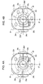
- the driver 20 includes a crank hub 22 serving as a first support member that is non-rotatably joined to an end of a drive shaft 34, a holder 24 serving as a second support member that is joined to the crank hub 22, and a linking member 26 that is rotatably supported by the holder 24.
- the drive shaft 34 is rotatably supported by a loom frame 32 by means of a bearing and has one end that projects from the loom frame 32.
- the drive shaft 34 is linked to a main shaft (not shown) of the loom by means of, for example, a drive transmission mechanism, and is rotated in synchronization with the main shaft.
- crank hub 22 is joined to the tip end of the drive shaft 34 that projects from the loom frame 32.
- the crank hub 22 has a through hole 22c extending in the axial direction of the drive shaft 34, and the crank hub 22 and the drive shaft 34 are combined together in a state where the tip end portion of the drive shaft 34 is fitted to this through hole 22c.
- the crank hub 22 is securely clamped to the drive shaft 34 with a clamping mechanism provided at a shaft portion 22a of the crank hub 22.
- the crank hub 22 is joined to the drive shaft 34 in a manner such that the phase of the crank hub 22 is freely adjustable with respect to the drive shaft 34.
- the position for securing the crank hub 22 to the drive shaft 34 is not limited to the tip end portion of the drive shaft 34.
- other members such as a rotation detector
- more distant from the loom frame 32 relative to the crank hub 22 may be attached to the drive shaft 34.
- the holder 24 is abutted against an end surface 22d, proximate to the loom frame 32, of a flange portion 22b of the crank hub 22.
- the holder 24 is joined to the crank hub 22 by means of a plurality of screw members (three screw members in Figs. 1 and 2 ) that are screwed in from the side of the crank hub 22.
- the holder 24 integrally has an eccentric shaft portion 24a that corresponds to an eccentric shaft according to the present invention.
- the holder 24 including the eccentric shaft portion 24a has a through hole 24b through which the drive shaft 34 extends.
- the holder 24 has a cutout 24g at one periphery section thereof. As will be described hereinafter, this cutout 24g serves as an indicator for the direction of eccentricity.
- the term "direction of eccentricity” refers to a direction in which the central axis of the eccentric shaft portion 24a is eccentric to the center of the through hole 22c in the crank hub 22 (i.e. the central axis of the drive shaft 34).
- a direction of a line that connects the central axis of the eccentric shaft portion 24a to the center of the cutout 24g, that is, a line extending through the center of the through hole 22c in a direction parallel to the direction of eccentricity, will be referred to as "first direction” hereinafter.
- the dimension of the through hole 24b in the first direction is greater than the diameter of the drive shaft 34. Consequently, in a state where the drive shaft 34 is fitted to the through hole 24b, the drive shaft 34 is permitted to move in the first direction.
- the linking member 26 is linked to the easing lever 12a (12b) by means of the rod 14, etc., and is concentrically engaged to the eccentric shaft portion 24a of the holder 24 with a bearing 28 therebetween, whereby the linking member 26 is rotatably supported by the holder 24.
- the linking member 26 and the holder 24 including the eccentric shaft portion 24a constitute a crank unit.
- the holder 24 in a state where the driver 20 is combined with the drive shaft 34, the holder 24 is joined to the crank hub 22 with a central axis L2 of the eccentric shaft portion 24a being eccentric to a central axis L1 of the drive shaft 34 (i.e. the center line of the through hole 22c).
- the central axis L2 is eccentric to the central axis L1 by an eccentricity amount e1 (see Fig. 3A ).
- an amount of reciprocation of the easing lever 12a (12b) depends on this eccentricity amount. Based on the angular relationship the crank hub 22 has with the rotational phase of the drive shaft 34, the timing at which the linked section between the easing lever 12a (12b) and the arm 16 reaches the rocking limit point farthest from the driver 20, namely, the timing at which the easing lever 12a (12b) in reciprocal rocking motion reaches the top dead center is determined.
- a line that connects the central axis L1 of the drive shaft 34 and the central axis L2 of the eccentric shaft portion 24a is aligned with a line that connects the central axis L2 of the eccentric shaft portion 24a and the center of the linked section between the easing lever 12a (12b) and the arm 16.
- the direction of eccentricity is aligned with the extending direction of the rod 14 and the arm 16.
- the crank hub 22 can be joined to the drive shaft 34 in a manner such that the direction of eccentricity is aligned with the extending direction of the rod 14 at a rotational phase of the drive shaft 34 that corresponds to the rotational angle of the loom main shaft at which the easing lever 12a (12b) reaches the top dead center. This allows the tension roller to perform a desired easing operation.
- the holder 24 has a surface 24e that abuts against the end surface 22d of the flange portion 22b of the crank hub 22.
- the holder 24 is provided with a pair of stoppers 24c and 24d that project towards the crank hub 22 from the surface 24e.
- the stoppers 24c and 24d are provided at positions where they sandwich the crank hub 22 in the first direction.
- the crank hub 22 i.e. the flange portion 22b
- the holder 24 is joined to the crank hub 22 with the edge surface 22b1 of the crank hub 22 and the stopper 24c being abutted against each other.
- the holder 24 is fixed to the crank hub 22 by inserting screw members through perforated holes formed in the crank hub 22 and then screwing the screw members into screw holes formed in the holder 24.
- the fixation position of the holder 24 with respect to the crank hub 22 is set by positioning therebetween on the basis of abutment between the stopper 24c of the holder 24 and the edge surface 22b1 or 22b2 of the crank hub 22. Furthermore, the screw holes formed in the holder 24 that are used for fixing the holder 24 to the crank hub 22 are provided at positions corresponding to the perforated holes of the crank hub 22 in a fixation position shown in Fig. 3A and at positions corresponding to the perforated holes of the crank hub 22 in a fixation position shown in Fig. 3B .
- the fixation position of the holder 24 with respect to the crank hub 22 is set on the basis of the abutment between the flange portion 22b of the crank hub 22 and the stopper 24c of the holder 24 and the positional relationship between the perforated holes in the crank hub 22 and the screw holes in the holder 24.
- the holder 24 can only be joined to the crank hub 22 at these settable fixation positions.
- the crank hub 22 also has a guide portion 22e that projects from the end surface 22d proximate to the loom frame 32.
- the holder 24 has a recess 24f at the upper end of the through hole 24b so as to receive the guide portion 22e.
- the guide portion 22e of the crank hub 22 has side surfaces opposite to each other in a direction perpendicular to the first direction (which will be referred to as "second direction” hereinafter). These opposite side surfaces extend parallel to the first direction at each of the aforementioned fixation positions.
- the recess 24f of the holder 24 has inner surfaces that face each other in the second direction.
- the inner surfaces of the recess 24f are parallel to the opposite side surfaces of the guide portion 22e of the crank hub 22 and are slidable against these opposite side surfaces so that the recess 24f can receive the guide portion 22e.
- the recess 24f is formed such that the center line thereof viewed in the second direction extends through the center of the eccentric shaft portion 24a and is positioned on the line extending in the first direction.
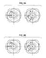
- Fig. 3A shows a fixation position where the angular position is in alignment with the direction of eccentricity and is 0°
- Fig. 3B shows a state where the relative angular position between the crank hub 22 and the holder 24 differs from that in Fig. 3A by 180°. Therefore, Fig. 3B corresponds to a fixation position where the angular position is 180°.
- the angular position is set as a rotational angle about the central axis of the drive shaft 34 and is relative between the crank hub 22 and the holder 24.
- a fixation position of the holder 24 with respect to the crank hub 22 is defined by such an angular position.
- the flange portion 22b of the crank hub 22 is formed such that a distance P1 between the center of the through hole 22c and the edge surface 22b1 is different from a distance P2 between the center of the through hole 22c and the edge surface 22b2 (P2 > P1 in Fig. 3A ). Consequently, by changing the relative angular position between the crank hub 22 and the holder 24 by 180° from the state of fixation position with 0° angular position shown in Fig. 3A , a fixation position with 180° angular position shown in Fig. 3B is attained. As a result, the eccentricity amount e1 shown in Fig. 3A is changed to an eccentricity amount e2 ( ⁇ e1).
- fixation positions at the two aforementioned angular positions (0° and 180°) are set.
- the edge surface 22b1 or 22b2 of the crank hub 22 and the stopper 24c of the holder 24 are abutted against each other so that the holder 24 is positioned with respect to the crank hub 22.
- the eccentricity amount of the central axis L2 of the eccentric shaft portion 24a with respect to the central axis L1 of the drive shaft 34 is different between the two fixation positions.
- the process for changing the drive amount by the driver 20 simply involves selecting one of the settable fixation positions (angular positions) and fixing the crank hub 22 and the holder 24 together with the holder 24 being positioned with respect to the crank hub 22 (with the flange portion 22b of the crank hub 22 being abutted against the stopper 24c of the holder 24). This process can thus be performed readily and accurately regardless of the level of skill of the operator.
- the angular position of the holder 24 with respect to the crank hub 22 in the present invention is relative between the crank hub 22 and the holder 24. Therefore, when performing the process for changing the fixation position (angular position) of the holder 24 with respect to the crank hub 22, the angular relationship the holder 24 has with the drive shaft 34 may be changed while maintaining the angular relationship the crank hub 22 has with the drive shaft 34, or the relative angular position between the crank hub 22 and the holder 24 may be changed by rotating the crank hub 22 around the drive shaft 34 while maintaining the angular relationship the holder 24 has with the drive shaft 34.
- the holder 24 is movable with respect to the crank hub 22 in the first direction at each of the angular positions for setting the aforementioned fixation positions.
- the distance between the stoppers 24c and 24d of the holder 24 is greater than the distance between the edge surfaces 22b1 and 22b2 of the crank hub 22, and the dimension of the recess 24f of the holder 24 in the first direction is greater than the dimension of the guide portion 22e of the crank hub 22 in the first direction, whereby relative movement is permitted between the crank hub 22 and the holder 24.
- the holder 24 becomes movable with respect to the crank hub 22 in a direction opposite to the direction of eccentricity from the state shown in Fig. 1 where the edge surface 22b1 of the crank hub 22 and the stopper 24c of the holder 24 are abutted against each other.
- This movement in the direction opposite to the direction of eccentricity is stopped when the edge surface 22b2 of the crank hub 22 and the stopper 24d of the holder 24 abut against each other.
- the holder 24 can be positioned with respect to the crank hub 22 at two predetermined positions at each angular position.
- the guide portion 22e of the crank hub 22 is guided along the inner surfaces of the recess 24f in the holder 24 that face each other in the second direction, so that the relative movement between the crank hub 22 and the holder 24 is permitted only in the first direction.
- the four fixation positions include the 0° angular position shown in Fig. 3A where the edge surface 22b1 of the crank hub 22 and the stopper 24c of the holder 24 are abutted against each other, the 180° angular position shown in Fig. 3B where the edge surface 22b2 of the crank hub 22 and the stopper 24c of the holder 24 are abutted against each other, a 0° angular position shown in Fig.
- the movable distance of the holder 24 with respect to the crank hub 22 is determined on the basis of the relationship between the dimension between the edge surfaces 22b1 and 22b2 of the crank hub 22 and the distance between the stoppers 24c and 24d of the holder 24. Consequently, by appropriately setting this movable distance and the relationship between the dimension (distance) between the center of the through hole 22c in the flange portion 22b of the crank hub 22 and the edge surface 22b1 and the dimension (distance) between the center of the through hole 22c and the edge surface 22b2, the eccentricity amount of the central axis L2 of the eccentric shaft portion 24a with respect to the central axis L1 of the drive shaft 34 can be made variable. In this case, four kinds of eccentricity amounts can be attained. In the present embodiment, the eccentricity amount in the state shown in Fig. 4A is e3 ( ⁇ e2), and the eccentricity amount in the state shown in Fig. 4B is e4 ( ⁇ e3).
- eccentricity amount it is possible to set the smallest eccentricity amount e4 to zero. Specifically, in a driver where a plurality of drive amounts (eccentricity amounts) can be set, it is possible to obtain a state where the eccentricity amount is zero.
- the driver 20 also has the following features.
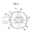
- the holder 24 can take a free position with respect to the drive shaft 34 upon releasing of the fixed state between the crank hub 22 and the holder 24.
- the center line of the through hole 24b becomes non-aligned with the central axis of the drive shaft 34.
- the inner wall of the through hole 24b in the holder 24 is partially provided with an arc surface 24h at a section facing the first direction.
- the arc surface 24h is formed such that the center thereof is positioned on the center line of the recess 24f in the second direction.
- the arc surface 24h guides the drive shaft 34 so that the central axis thereof can be positioned on a line extending in the first direction through the center of the arc surface 24h, namely, the center line of the recess 24f in the second direction. Consequently, this facilitates the process for engaging the guide portion 22e of the crank hub 22 to the recess 24f of the holder 24 in a state where the drive shaft 34 is fitted to the through hole 22c of the crank hub 22.
- the arc surface 24h has an arc with a central angle of 180° or less and with a radius that is slightly larger than the radius of the drive shaft 34.
- a surface for guiding the drive shaft 34 in the above-described manner is not limited to an arc surface, and may be defined by, for example, two surfaces that converge towards the center line of the recess 24f in the second direction from the inner surfaces of the recess 24f that face each other in the second direction.
- an external force acting in the direction for pressing the arc surface 24h against the drive shaft 34 is utilized in order to guide the central axis of the drive shaft 34 onto the center line of the recess 24f in the second direction.
- a similar effect can be achieved with the weight of the holder 24 itself and the weight of the linking member 26 itself joined to the holder 24 with the bearing.
- a downward force acts on the holder 24 due to its own weight, but the holder 24 is supported by the drive shaft 34 fitted to the through hole 24b.
- the holder 24 is rotated gradually until the arc surface 24h is oriented in the direction opposite to the direction of the weight of the holder 24. Finally, the central axis of the drive shaft 34 is guided by the arc surface 24h onto the center line of the recess 24f in the second direction.
- the arc surface 24h is preferably provided at an inner wall that faces the direction opposite to the direction of eccentricity as shown in Fig. 5 , instead of an inner wall of the recess 24f that faces the direction of eccentricity.
Landscapes
- Engineering & Computer Science (AREA)
- Textile Engineering (AREA)
- General Engineering & Computer Science (AREA)
- Mechanical Engineering (AREA)
- Transmission Devices (AREA)
- Shafts, Cranks, Connecting Bars, And Related Bearings (AREA)
- Looms (AREA)
Applications Claiming Priority (1)
| Application Number | Priority Date | Filing Date | Title |
|---|---|---|---|
| JP2007014387A JP4884992B2 (ja) | 2007-01-25 | 2007-01-25 | クランク式駆動装置における駆動量変更機構 |
Publications (1)
| Publication Number | Publication Date |
|---|---|
| EP1950332A1 true EP1950332A1 (fr) | 2008-07-30 |
Family
ID=39156071
Family Applications (1)
| Application Number | Title | Priority Date | Filing Date |
|---|---|---|---|
| EP08000508A Withdrawn EP1950332A1 (fr) | 2007-01-25 | 2008-01-11 | Mécanisme de changement de quantité d'entraînement dans un mécanisme de transmission de type manivelle |
Country Status (3)
| Country | Link |
|---|---|
| EP (1) | EP1950332A1 (fr) |
| JP (1) | JP4884992B2 (fr) |
| CN (1) | CN101230902B (fr) |
Cited By (4)
| Publication number | Priority date | Publication date | Assignee | Title |
|---|---|---|---|---|
| EP2937451A1 (fr) * | 2014-04-24 | 2015-10-28 | Tsudakoma Kogyo Kabushiki Kaisha | Dispositif de rétraction de rouleau de relâchement pour métier à tisser |
| EP3009548A3 (fr) * | 2014-10-17 | 2016-05-18 | Tsudakoma Kogyo Kabushiki Kaisha | Appareil d'entraînement à manivelle |
| EP3009549A3 (fr) * | 2014-10-15 | 2016-05-18 | Tsudakoma Kogyo Kabushiki Kaisha | Mécanisme de changement de monture d'entraînement pour appareil d'entraînement à manivelle |
| US11591725B2 (en) | 2020-11-24 | 2023-02-28 | Tsudakoma Kogyo Kabushiki Kaisha | Crank-type drive device for loom |
Families Citing this family (4)
| Publication number | Priority date | Publication date | Assignee | Title |
|---|---|---|---|---|
| JP5410814B2 (ja) * | 2009-04-02 | 2014-02-05 | 津田駒工業株式会社 | 織機における製織関連装置用の駆動機構 |
| US9765865B2 (en) * | 2013-02-07 | 2017-09-19 | Medinol Ltd. | Variable linear motor |
| CN103132214A (zh) * | 2013-03-19 | 2013-06-05 | 无锡精业丝普兰科技股份有限公司 | 喷气织机的平稳量电子调整机构 |
| CN105624891B (zh) * | 2016-03-07 | 2017-07-18 | 青岛东佳机械制造有限公司 | 一种喷气织机 |
Citations (4)
| Publication number | Priority date | Publication date | Assignee | Title |
|---|---|---|---|---|
| BE1005152A6 (nl) * | 1991-07-24 | 1993-05-04 | Picanol Nv | Inrichting voor het verplaatsen van een sleep bij weefmachines. |
| JPH0742046A (ja) | 1993-07-26 | 1995-02-10 | Toyota Autom Loom Works Ltd | 織機における経糸張力検出装置 |
| JPH07133545A (ja) | 1993-11-05 | 1995-05-23 | Tsudakoma Corp | クランク装置の駆動量変更機構 |
| JPH10331054A (ja) | 1997-05-30 | 1998-12-15 | Tsudakoma Corp | パイル形成装置 |
Family Cites Families (7)
| Publication number | Priority date | Publication date | Assignee | Title |
|---|---|---|---|---|
| JPS6128940A (ja) * | 1984-07-20 | 1986-02-08 | Nippon Telegr & Teleph Corp <Ntt> | 微細パタ−ン形成法及びその装置 |
| JPS6266274A (ja) * | 1985-09-19 | 1987-03-25 | Canon Inc | 両面複写装置 |
| JP3276843B2 (ja) * | 1996-05-13 | 2002-04-22 | ブラザー工業株式会社 | 偏心輪装置における偏心量調節装置 |
| TW371705B (en) * | 1997-04-09 | 1999-10-11 | Nikkiso Co Ltd | Stroke length adjustment device |
| JPH11125317A (ja) * | 1997-10-23 | 1999-05-11 | Tsudakoma Corp | 偏心駆動装置と、それを使用する織機のイージング装置 |
| CN1102209C (zh) * | 1999-07-29 | 2003-02-26 | 宋家骏 | 曲柄摇杆机构的可调曲柄 |
| JP2004314953A (ja) * | 2003-04-18 | 2004-11-11 | Johnson Electric Sa | ワイパー機構 |
-
2007
- 2007-01-25 JP JP2007014387A patent/JP4884992B2/ja active Active
-
2008
- 2008-01-03 CN CN200810001913XA patent/CN101230902B/zh active Active
- 2008-01-11 EP EP08000508A patent/EP1950332A1/fr not_active Withdrawn
Patent Citations (4)
| Publication number | Priority date | Publication date | Assignee | Title |
|---|---|---|---|---|
| BE1005152A6 (nl) * | 1991-07-24 | 1993-05-04 | Picanol Nv | Inrichting voor het verplaatsen van een sleep bij weefmachines. |
| JPH0742046A (ja) | 1993-07-26 | 1995-02-10 | Toyota Autom Loom Works Ltd | 織機における経糸張力検出装置 |
| JPH07133545A (ja) | 1993-11-05 | 1995-05-23 | Tsudakoma Corp | クランク装置の駆動量変更機構 |
| JPH10331054A (ja) | 1997-05-30 | 1998-12-15 | Tsudakoma Corp | パイル形成装置 |
Cited By (4)
| Publication number | Priority date | Publication date | Assignee | Title |
|---|---|---|---|---|
| EP2937451A1 (fr) * | 2014-04-24 | 2015-10-28 | Tsudakoma Kogyo Kabushiki Kaisha | Dispositif de rétraction de rouleau de relâchement pour métier à tisser |
| EP3009549A3 (fr) * | 2014-10-15 | 2016-05-18 | Tsudakoma Kogyo Kabushiki Kaisha | Mécanisme de changement de monture d'entraînement pour appareil d'entraînement à manivelle |
| EP3009548A3 (fr) * | 2014-10-17 | 2016-05-18 | Tsudakoma Kogyo Kabushiki Kaisha | Appareil d'entraînement à manivelle |
| US11591725B2 (en) | 2020-11-24 | 2023-02-28 | Tsudakoma Kogyo Kabushiki Kaisha | Crank-type drive device for loom |
Also Published As
| Publication number | Publication date |
|---|---|
| JP4884992B2 (ja) | 2012-02-29 |
| JP2008180289A (ja) | 2008-08-07 |
| CN101230902A (zh) | 2008-07-30 |
| CN101230902B (zh) | 2012-11-21 |
Similar Documents
| Publication | Publication Date | Title |
|---|---|---|
| EP1950332A1 (fr) | Mécanisme de changement de quantité d'entraînement dans un mécanisme de transmission de type manivelle | |
| JP4955325B2 (ja) | 織機のロールの支持装置 | |
| EP2584079B1 (fr) | Métier à tisser avec un appareil de détection de tension | |
| US8973620B2 (en) | Connecting rod for a weaving loom and weaving loom comprising this connecting rod | |
| JPH06158470A (ja) | 織機に使用されるカム機構 | |
| CN204985576U (zh) | 曲柄式驱动装置中的驱动量变更机构 | |
| CN216040059U (zh) | 织机的曲柄式驱动装置 | |
| EP2937451B1 (fr) | Dispositif de rétraction de rouleau de relâchement pour métier à tisser | |
| CN203270117U (zh) | 钳子隔距调节设备 | |
| GB2063933A (en) | Terry motions | |
| US20060021667A1 (en) | Driving system for terry motion members in cloth-shifting-type pile loom | |
| JP6463070B2 (ja) | クランク式駆動装置 | |
| JP2004510893A (ja) | 運動伝達要素上にヘルドフレームを連結するための装置、駆動アセンブリ及びそのようなアセンブリを備えた織機 | |
| US7617845B2 (en) | Heald shaft | |
| JP7491819B2 (ja) | 織機のクランク式駆動装置 | |
| EP1302580B1 (fr) | Dispositif pour soutenir un templet et son couvercle dans un métier à tisser un tissu éponge | |
| JP2010024594A (ja) | 織機における開口装置 | |
| EP3312323B2 (fr) | Dispositif de déroulement de la chaîne d'un métier à tisser | |
| EP4219813A1 (fr) | Ensemble de formation de la foule pour un métier à tisser et son procédé de réglage | |
| KR101343412B1 (ko) | 커넥팅 로드와 헤들 프레임을 결합시키는 장치, 상기 장치에 구비된 헤들 프레임, 상기 프레임을 작동시키는 기계, 및 상기 기계를 포함하는 직기 | |
| JP2018143397A (ja) | 縫製装置の縫い針取付け機構、および、縫い針取付け機構を備えた縫製装置 | |
| JPH0368135B2 (fr) |
Legal Events
| Date | Code | Title | Description |
|---|---|---|---|
| PUAI | Public reference made under article 153(3) epc to a published international application that has entered the european phase |
Free format text: ORIGINAL CODE: 0009012 |
|
| AK | Designated contracting states |
Kind code of ref document: A1 Designated state(s): AT BE BG CH CY CZ DE DK EE ES FI FR GB GR HR HU IE IS IT LI LT LU LV MC MT NL NO PL PT RO SE SI SK TR |
|
| AX | Request for extension of the european patent |
Extension state: AL BA MK RS |
|
| AKX | Designation fees paid | ||
| STAA | Information on the status of an ep patent application or granted ep patent |
Free format text: STATUS: THE APPLICATION IS DEEMED TO BE WITHDRAWN |
|
| 18D | Application deemed to be withdrawn |
Effective date: 20090131 |
|
| REG | Reference to a national code |
Ref country code: DE Ref legal event code: 8566 |