EP1950318B1 - Gesinterte aktuatoren auf eisenbasis und ihre herstellung - Google Patents
Gesinterte aktuatoren auf eisenbasis und ihre herstellung Download PDFInfo
- Publication number
- EP1950318B1 EP1950318B1 EP06833103.2A EP06833103A EP1950318B1 EP 1950318 B1 EP1950318 B1 EP 1950318B1 EP 06833103 A EP06833103 A EP 06833103A EP 1950318 B1 EP1950318 B1 EP 1950318B1
- Authority
- EP
- European Patent Office
- Prior art keywords
- iron
- powder
- nickel
- sintered part
- carbon
- Prior art date
- Legal status (The legal status is an assumption and is not a legal conclusion. Google has not performed a legal analysis and makes no representation as to the accuracy of the status listed.)
- Ceased
Links
- 238000004519 manufacturing process Methods 0.000 title claims description 14
- 239000000843 powder Substances 0.000 claims description 88
- PXHVJJICTQNCMI-UHFFFAOYSA-N Nickel Chemical compound [Ni] PXHVJJICTQNCMI-UHFFFAOYSA-N 0.000 claims description 76
- 238000000465 moulding Methods 0.000 claims description 58
- 238000000034 method Methods 0.000 claims description 53
- OKTJSMMVPCPJKN-UHFFFAOYSA-N Carbon Chemical compound [C] OKTJSMMVPCPJKN-UHFFFAOYSA-N 0.000 claims description 45
- 229910045601 alloy Inorganic materials 0.000 claims description 40
- 239000000956 alloy Substances 0.000 claims description 40
- 229910052751 metal Inorganic materials 0.000 claims description 36
- 239000002184 metal Substances 0.000 claims description 35
- 229910052759 nickel Inorganic materials 0.000 claims description 34
- 229910052799 carbon Inorganic materials 0.000 claims description 31
- XEEYBQQBJWHFJM-UHFFFAOYSA-N Iron Chemical compound [Fe] XEEYBQQBJWHFJM-UHFFFAOYSA-N 0.000 claims description 28
- 229910052750 molybdenum Inorganic materials 0.000 claims description 24
- ZOKXTWBITQBERF-UHFFFAOYSA-N Molybdenum Chemical compound [Mo] ZOKXTWBITQBERF-UHFFFAOYSA-N 0.000 claims description 19
- 239000000203 mixture Substances 0.000 claims description 19
- 239000011733 molybdenum Substances 0.000 claims description 19
- 238000005245 sintering Methods 0.000 claims description 18
- 239000000314 lubricant Substances 0.000 claims description 17
- 238000007596 consolidation process Methods 0.000 claims description 15
- 150000004668 long chain fatty acids Chemical class 0.000 claims description 14
- 238000010791 quenching Methods 0.000 claims description 14
- 230000000171 quenching effect Effects 0.000 claims description 14
- 229910052742 iron Inorganic materials 0.000 claims description 12
- HGPXWXLYXNVULB-UHFFFAOYSA-M lithium stearate Chemical compound [Li+].CCCCCCCCCCCCCCCCCC([O-])=O HGPXWXLYXNVULB-UHFFFAOYSA-M 0.000 claims description 12
- 239000010949 copper Substances 0.000 claims description 11
- 229910052802 copper Inorganic materials 0.000 claims description 10
- 238000010438 heat treatment Methods 0.000 claims description 9
- 239000012535 impurity Substances 0.000 claims description 8
- 239000000463 material Substances 0.000 claims description 8
- RYGMFSIKBFXOCR-UHFFFAOYSA-N Copper Chemical compound [Cu] RYGMFSIKBFXOCR-UHFFFAOYSA-N 0.000 claims description 6
- VAWNDNOTGRTLLU-UHFFFAOYSA-N iron molybdenum nickel Chemical compound [Fe].[Ni].[Mo] VAWNDNOTGRTLLU-UHFFFAOYSA-N 0.000 claims description 4
- XHRHIGDKHNLSKA-UHFFFAOYSA-N [Mo].[Ni].[C].[Fe] Chemical compound [Mo].[Ni].[C].[Fe] XHRHIGDKHNLSKA-UHFFFAOYSA-N 0.000 claims description 3
- 230000002093 peripheral effect Effects 0.000 claims description 3
- CJZGTCYPCWQAJB-UHFFFAOYSA-L calcium stearate Chemical compound [Ca+2].CCCCCCCCCCCCCCCCCC([O-])=O.CCCCCCCCCCCCCCCCCC([O-])=O CJZGTCYPCWQAJB-UHFFFAOYSA-L 0.000 claims description 2
- 239000008116 calcium stearate Substances 0.000 claims description 2
- 235000013539 calcium stearate Nutrition 0.000 claims description 2
- 238000005299 abrasion Methods 0.000 description 26
- 230000001965 increasing effect Effects 0.000 description 18
- 229910001566 austenite Inorganic materials 0.000 description 14
- 229910000734 martensite Inorganic materials 0.000 description 14
- IJGRMHOSHXDMSA-UHFFFAOYSA-N Atomic nitrogen Chemical compound N#N IJGRMHOSHXDMSA-UHFFFAOYSA-N 0.000 description 12
- 239000003795 chemical substances by application Substances 0.000 description 10
- 239000007789 gas Substances 0.000 description 8
- 239000007788 liquid Substances 0.000 description 7
- 230000000052 comparative effect Effects 0.000 description 6
- 229910052757 nitrogen Inorganic materials 0.000 description 6
- XLYOFNOQVPJJNP-UHFFFAOYSA-N water Substances O XLYOFNOQVPJJNP-UHFFFAOYSA-N 0.000 description 6
- 239000002344 surface layer Substances 0.000 description 5
- 229910001563 bainite Inorganic materials 0.000 description 4
- 238000000280 densification Methods 0.000 description 4
- 239000012530 fluid Substances 0.000 description 4
- 230000001788 irregular Effects 0.000 description 4
- 230000001050 lubricating effect Effects 0.000 description 4
- 238000002156 mixing Methods 0.000 description 4
- 238000005255 carburizing Methods 0.000 description 3
- 238000000576 coating method Methods 0.000 description 3
- 238000001816 cooling Methods 0.000 description 3
- 230000003247 decreasing effect Effects 0.000 description 3
- 239000011148 porous material Substances 0.000 description 3
- 238000005496 tempering Methods 0.000 description 3
- QVGXLLKOCUKJST-UHFFFAOYSA-N atomic oxygen Chemical compound [O] QVGXLLKOCUKJST-UHFFFAOYSA-N 0.000 description 2
- 239000010953 base metal Substances 0.000 description 2
- 239000011248 coating agent Substances 0.000 description 2
- 238000002485 combustion reaction Methods 0.000 description 2
- 230000000694 effects Effects 0.000 description 2
- 230000002708 enhancing effect Effects 0.000 description 2
- 239000002923 metal particle Substances 0.000 description 2
- 239000001301 oxygen Substances 0.000 description 2
- 229910052760 oxygen Inorganic materials 0.000 description 2
- 239000002245 particle Substances 0.000 description 2
- 238000013001 point bending Methods 0.000 description 2
- 150000003839 salts Chemical class 0.000 description 2
- 238000005507 spraying Methods 0.000 description 2
- XOOUIPVCVHRTMJ-UHFFFAOYSA-L zinc stearate Chemical compound [Zn+2].CCCCCCCCCCCCCCCCCC([O-])=O.CCCCCCCCCCCCCCCCCC([O-])=O XOOUIPVCVHRTMJ-UHFFFAOYSA-L 0.000 description 2
- 244000048199 Hibiscus mutabilis Species 0.000 description 1
- 229910017263 Mo—C Inorganic materials 0.000 description 1
- 229910017320 Mo—Ni—C Inorganic materials 0.000 description 1
- 229910000978 Pb alloy Inorganic materials 0.000 description 1
- 229910000831 Steel Inorganic materials 0.000 description 1
- 238000000137 annealing Methods 0.000 description 1
- 159000000007 calcium salts Chemical class 0.000 description 1
- 238000010273 cold forging Methods 0.000 description 1
- 238000005056 compaction Methods 0.000 description 1
- 239000002131 composite material Substances 0.000 description 1
- 238000000354 decomposition reaction Methods 0.000 description 1
- 229910002804 graphite Inorganic materials 0.000 description 1
- 239000010439 graphite Substances 0.000 description 1
- FRVCGRDGKAINSV-UHFFFAOYSA-L iron(2+);octadecanoate Chemical compound [Fe+2].CCCCCCCCCCCCCCCCCC([O-])=O.CCCCCCCCCCCCCCCCCC([O-])=O FRVCGRDGKAINSV-UHFFFAOYSA-L 0.000 description 1
- 229910052745 lead Inorganic materials 0.000 description 1
- 229910003002 lithium salt Inorganic materials 0.000 description 1
- 159000000002 lithium salts Chemical class 0.000 description 1
- 229910052748 manganese Inorganic materials 0.000 description 1
- 238000005259 measurement Methods 0.000 description 1
- 238000010303 mechanochemical reaction Methods 0.000 description 1
- 238000002844 melting Methods 0.000 description 1
- 230000008018 melting Effects 0.000 description 1
- 239000007769 metal material Substances 0.000 description 1
- 230000001590 oxidative effect Effects 0.000 description 1
- 230000000149 penetrating effect Effects 0.000 description 1
- 239000012255 powdered metal Substances 0.000 description 1
- 238000003825 pressing Methods 0.000 description 1
- 238000005096 rolling process Methods 0.000 description 1
- 239000007921 spray Substances 0.000 description 1
- 239000010959 steel Substances 0.000 description 1
- 239000000161 steel melt Substances 0.000 description 1
- 238000010998 test method Methods 0.000 description 1
- 150000003751 zinc Chemical class 0.000 description 1
Images




Classifications
-
- F—MECHANICAL ENGINEERING; LIGHTING; HEATING; WEAPONS; BLASTING
- F04—POSITIVE - DISPLACEMENT MACHINES FOR LIQUIDS; PUMPS FOR LIQUIDS OR ELASTIC FLUIDS
- F04C—ROTARY-PISTON, OR OSCILLATING-PISTON, POSITIVE-DISPLACEMENT MACHINES FOR LIQUIDS; ROTARY-PISTON, OR OSCILLATING-PISTON, POSITIVE-DISPLACEMENT PUMPS
- F04C2/00—Rotary-piston machines or pumps
- F04C2/30—Rotary-piston machines or pumps having the characteristics covered by two or more groups F04C2/02, F04C2/08, F04C2/22, F04C2/24 or having the characteristics covered by one of these groups together with some other type of movement between co-operating members
- F04C2/34—Rotary-piston machines or pumps having the characteristics covered by two or more groups F04C2/02, F04C2/08, F04C2/22, F04C2/24 or having the characteristics covered by one of these groups together with some other type of movement between co-operating members having the movement defined in groups F04C2/08 or F04C2/22 and relative reciprocation between the co-operating members
- F04C2/344—Rotary-piston machines or pumps having the characteristics covered by two or more groups F04C2/02, F04C2/08, F04C2/22, F04C2/24 or having the characteristics covered by one of these groups together with some other type of movement between co-operating members having the movement defined in groups F04C2/08 or F04C2/22 and relative reciprocation between the co-operating members with vanes reciprocating with respect to the inner member
- F04C2/3446—Rotary-piston machines or pumps having the characteristics covered by two or more groups F04C2/02, F04C2/08, F04C2/22, F04C2/24 or having the characteristics covered by one of these groups together with some other type of movement between co-operating members having the movement defined in groups F04C2/08 or F04C2/22 and relative reciprocation between the co-operating members with vanes reciprocating with respect to the inner member the inner and outer member being in contact along more than one line or surface
-
- B—PERFORMING OPERATIONS; TRANSPORTING
- B22—CASTING; POWDER METALLURGY
- B22F—WORKING METALLIC POWDER; MANUFACTURE OF ARTICLES FROM METALLIC POWDER; MAKING METALLIC POWDER; APPARATUS OR DEVICES SPECIALLY ADAPTED FOR METALLIC POWDER
- B22F3/00—Manufacture of workpieces or articles from metallic powder characterised by the manner of compacting or sintering; Apparatus specially adapted therefor ; Presses and furnaces
- B22F3/10—Sintering only
- B22F3/1003—Use of special medium during sintering, e.g. sintering aid
- B22F3/1007—Atmosphere
-
- B—PERFORMING OPERATIONS; TRANSPORTING
- B22—CASTING; POWDER METALLURGY
- B22F—WORKING METALLIC POWDER; MANUFACTURE OF ARTICLES FROM METALLIC POWDER; MAKING METALLIC POWDER; APPARATUS OR DEVICES SPECIALLY ADAPTED FOR METALLIC POWDER
- B22F3/00—Manufacture of workpieces or articles from metallic powder characterised by the manner of compacting or sintering; Apparatus specially adapted therefor ; Presses and furnaces
- B22F3/24—After-treatment of workpieces or articles
-
- B—PERFORMING OPERATIONS; TRANSPORTING
- B22—CASTING; POWDER METALLURGY
- B22F—WORKING METALLIC POWDER; MANUFACTURE OF ARTICLES FROM METALLIC POWDER; MAKING METALLIC POWDER; APPARATUS OR DEVICES SPECIALLY ADAPTED FOR METALLIC POWDER
- B22F5/00—Manufacture of workpieces or articles from metallic powder characterised by the special shape of the product
- B22F5/08—Manufacture of workpieces or articles from metallic powder characterised by the special shape of the product of toothed articles, e.g. gear wheels; of cam discs
-
- C—CHEMISTRY; METALLURGY
- C22—METALLURGY; FERROUS OR NON-FERROUS ALLOYS; TREATMENT OF ALLOYS OR NON-FERROUS METALS
- C22C—ALLOYS
- C22C33/00—Making ferrous alloys
- C22C33/02—Making ferrous alloys by powder metallurgy
- C22C33/0257—Making ferrous alloys by powder metallurgy characterised by the range of the alloying elements
- C22C33/0264—Making ferrous alloys by powder metallurgy characterised by the range of the alloying elements the maximum content of each alloying element not exceeding 5%
-
- C—CHEMISTRY; METALLURGY
- C22—METALLURGY; FERROUS OR NON-FERROUS ALLOYS; TREATMENT OF ALLOYS OR NON-FERROUS METALS
- C22C—ALLOYS
- C22C38/00—Ferrous alloys, e.g. steel alloys
- C22C38/08—Ferrous alloys, e.g. steel alloys containing nickel
-
- C—CHEMISTRY; METALLURGY
- C22—METALLURGY; FERROUS OR NON-FERROUS ALLOYS; TREATMENT OF ALLOYS OR NON-FERROUS METALS
- C22C—ALLOYS
- C22C38/00—Ferrous alloys, e.g. steel alloys
- C22C38/12—Ferrous alloys, e.g. steel alloys containing tungsten, tantalum, molybdenum, vanadium, or niobium
-
- C—CHEMISTRY; METALLURGY
- C22—METALLURGY; FERROUS OR NON-FERROUS ALLOYS; TREATMENT OF ALLOYS OR NON-FERROUS METALS
- C22C—ALLOYS
- C22C38/00—Ferrous alloys, e.g. steel alloys
- C22C38/16—Ferrous alloys, e.g. steel alloys containing copper
-
- F—MECHANICAL ENGINEERING; LIGHTING; HEATING; WEAPONS; BLASTING
- F01—MACHINES OR ENGINES IN GENERAL; ENGINE PLANTS IN GENERAL; STEAM ENGINES
- F01C—ROTARY-PISTON OR OSCILLATING-PISTON MACHINES OR ENGINES
- F01C21/00—Component parts, details or accessories not provided for in groups F01C1/00 - F01C20/00
- F01C21/08—Rotary pistons
-
- F—MECHANICAL ENGINEERING; LIGHTING; HEATING; WEAPONS; BLASTING
- F01—MACHINES OR ENGINES IN GENERAL; ENGINE PLANTS IN GENERAL; STEAM ENGINES
- F01C—ROTARY-PISTON OR OSCILLATING-PISTON MACHINES OR ENGINES
- F01C21/00—Component parts, details or accessories not provided for in groups F01C1/00 - F01C20/00
- F01C21/10—Outer members for co-operation with rotary pistons; Casings
- F01C21/104—Stators; Members defining the outer boundaries of the working chamber
- F01C21/106—Stators; Members defining the outer boundaries of the working chamber with a radial surface, e.g. cam rings
-
- B—PERFORMING OPERATIONS; TRANSPORTING
- B22—CASTING; POWDER METALLURGY
- B22F—WORKING METALLIC POWDER; MANUFACTURE OF ARTICLES FROM METALLIC POWDER; MAKING METALLIC POWDER; APPARATUS OR DEVICES SPECIALLY ADAPTED FOR METALLIC POWDER
- B22F3/00—Manufacture of workpieces or articles from metallic powder characterised by the manner of compacting or sintering; Apparatus specially adapted therefor ; Presses and furnaces
- B22F3/02—Compacting only
- B22F2003/023—Lubricant mixed with the metal powder
-
- B—PERFORMING OPERATIONS; TRANSPORTING
- B22—CASTING; POWDER METALLURGY
- B22F—WORKING METALLIC POWDER; MANUFACTURE OF ARTICLES FROM METALLIC POWDER; MAKING METALLIC POWDER; APPARATUS OR DEVICES SPECIALLY ADAPTED FOR METALLIC POWDER
- B22F3/00—Manufacture of workpieces or articles from metallic powder characterised by the manner of compacting or sintering; Apparatus specially adapted therefor ; Presses and furnaces
- B22F3/02—Compacting only
- B22F2003/026—Mold wall lubrication or article surface lubrication
-
- B—PERFORMING OPERATIONS; TRANSPORTING
- B22—CASTING; POWDER METALLURGY
- B22F—WORKING METALLIC POWDER; MANUFACTURE OF ARTICLES FROM METALLIC POWDER; MAKING METALLIC POWDER; APPARATUS OR DEVICES SPECIALLY ADAPTED FOR METALLIC POWDER
- B22F2998/00—Supplementary information concerning processes or compositions relating to powder metallurgy
- B22F2998/10—Processes characterised by the sequence of their steps
-
- F—MECHANICAL ENGINEERING; LIGHTING; HEATING; WEAPONS; BLASTING
- F04—POSITIVE - DISPLACEMENT MACHINES FOR LIQUIDS; PUMPS FOR LIQUIDS OR ELASTIC FLUIDS
- F04C—ROTARY-PISTON, OR OSCILLATING-PISTON, POSITIVE-DISPLACEMENT MACHINES FOR LIQUIDS; ROTARY-PISTON, OR OSCILLATING-PISTON, POSITIVE-DISPLACEMENT PUMPS
- F04C2230/00—Manufacture
- F04C2230/20—Manufacture essentially without removing material
- F04C2230/22—Manufacture essentially without removing material by sintering
-
- F—MECHANICAL ENGINEERING; LIGHTING; HEATING; WEAPONS; BLASTING
- F05—INDEXING SCHEMES RELATING TO ENGINES OR PUMPS IN VARIOUS SUBCLASSES OF CLASSES F01-F04
- F05C—INDEXING SCHEME RELATING TO MATERIALS, MATERIAL PROPERTIES OR MATERIAL CHARACTERISTICS FOR MACHINES, ENGINES OR PUMPS OTHER THAN NON-POSITIVE-DISPLACEMENT MACHINES OR ENGINES
- F05C2201/00—Metals
- F05C2201/04—Heavy metals
- F05C2201/0403—Refractory metals, e.g. V, W
- F05C2201/0409—Molybdenum
-
- F—MECHANICAL ENGINEERING; LIGHTING; HEATING; WEAPONS; BLASTING
- F05—INDEXING SCHEMES RELATING TO ENGINES OR PUMPS IN VARIOUS SUBCLASSES OF CLASSES F01-F04
- F05C—INDEXING SCHEME RELATING TO MATERIALS, MATERIAL PROPERTIES OR MATERIAL CHARACTERISTICS FOR MACHINES, ENGINES OR PUMPS OTHER THAN NON-POSITIVE-DISPLACEMENT MACHINES OR ENGINES
- F05C2201/00—Metals
- F05C2201/04—Heavy metals
- F05C2201/0433—Iron group; Ferrous alloys, e.g. steel
- F05C2201/0448—Steel
- F05C2201/046—Stainless steel or inox, e.g. 18-8
-
- F—MECHANICAL ENGINEERING; LIGHTING; HEATING; WEAPONS; BLASTING
- F05—INDEXING SCHEMES RELATING TO ENGINES OR PUMPS IN VARIOUS SUBCLASSES OF CLASSES F01-F04
- F05C—INDEXING SCHEME RELATING TO MATERIALS, MATERIAL PROPERTIES OR MATERIAL CHARACTERISTICS FOR MACHINES, ENGINES OR PUMPS OTHER THAN NON-POSITIVE-DISPLACEMENT MACHINES OR ENGINES
- F05C2201/00—Metals
- F05C2201/04—Heavy metals
- F05C2201/0433—Iron group; Ferrous alloys, e.g. steel
- F05C2201/0466—Nickel
-
- Y—GENERAL TAGGING OF NEW TECHNOLOGICAL DEVELOPMENTS; GENERAL TAGGING OF CROSS-SECTIONAL TECHNOLOGIES SPANNING OVER SEVERAL SECTIONS OF THE IPC; TECHNICAL SUBJECTS COVERED BY FORMER USPC CROSS-REFERENCE ART COLLECTIONS [XRACs] AND DIGESTS
- Y10—TECHNICAL SUBJECTS COVERED BY FORMER USPC
- Y10T—TECHNICAL SUBJECTS COVERED BY FORMER US CLASSIFICATION
- Y10T74/00—Machine element or mechanism
- Y10T74/18—Mechanical movements
- Y10T74/18544—Rotary to gyratory
Definitions
- the present invention relates to a manufacturing method of an actuator and an actuator.
- Patent Reference 1 discloses a manufacturing method of a sintered part, in which carbon of 0.6 to 0.9 wt% is added in a composite alloy iron base powder, including Ni, Cu, Mo, etc., the powder combined with zinc stearate as a forming lubricant is put into a molding die, a forming body having density of 7.0 to 7.2 g/cm 3 is formed, the forming body is sintered at a temperature of 1250 to 1300 °C and then is cooled continuously, thereby generating a martensite-bainite mixed composition.
- Patent Reference 2 discloses Fe-base alloy having superior abrasion resistance, which is formed by impregnating a carbide precipitated type Fe-base sintered alloy having 5 to 20 % porosity with Pb or Pb alloy.
- the alloy disclosed in the above Patent Reference 1 relates to a method for generating a martensite-bainite mixed composition through continuous cooling, which does not include a carburization quenching process of rapid cooling after carburization.
- the density of 7.0 to 7.2 g/cm 3 is likely high for sintered metal, however it is not always considered high density. This is assumed from the method of charging a metal powder into a cavity of a molding die at a normal temperature or the process of using zinc stearate as a forming lubricant in the technique disclosed in Patent Reference 1.
- residual austenite which is effective for securing toughness, is not generated. It is also described in paragraph No. 0017 in Patent Reference 1 that residual austenite is not generated.
- the alloy disclosed in Patent Reference 2 is not subjected to a carburization quenching process.
- EP1273769 (A2 ) discloses a cam lobe piece of a built-up type camshaft for an internal combustion engine.
- the built-up type camshaft includes a hollow shaft fixedly inserted in a shaft opening of the cam lobe piece upon diametrical expansion of the hollow shaft.
- the cam lobe piece comprises a base circle section having the shaft opening, and a cam lobe section formed integral with the base circle section.
- EP1184476 mentions a sintered iron-based powder metal body with outstandingly lower re-compacting load and having a high density and a method of manufacturing an iron-based sintered component with fewer pores of a sharp shape and having high strength and high density, the method comprising mixing, an iron-based metal powder containing at most about 0.05% of carbon, at most about 0.3% of oxygen, at most about 0.010% of nitrogen, with at least about 0.03% and at most about 0.5% of graphite powder and a lubricant, preliminarily compacting the mixture into a preform, the density of which is about 7.3 Mg/m 3 or more, and preliminarily sintering the preform in a non-oxidizing atmosphere in which a partial pressure of nitrogen is about 30 kPa or less at a temperature of about 1000 °C or higher and about 1300 °C or lower; thereby forming a sintered iron-based powder metal body with outstandingly lower re-compacting load and having high deform
- US2003228949 discloses a sintered sprocket.
- the tooth surface layer contains carbon in the range from 0.6 to 1.2 mass % and nitrogen in the range from 0.05 to 0.5 mass %.
- the structure of the tooth surface layer comprises a tempered martensite structure and a residual austenitic structure, the residual austenitic structure being 10 to 50 volume % of the tooth surface layer.
- the density of the tooth surface layer is at least 7.4 g/cm 3 .
- Metallic elements contained in a base material comprise at least one metal selected from Ni, Cu and Mo in an amount in the range from 0.5 to 5 mass % the balance being Fe and inevitable impurities.
- the sintered sprocket exhibits high strength and wear resistance and can be manufactured at low cost.
- GB1378844 discloses a prealloyed steel powder comprising: C up to 0.5% Cu 0.8-5% Mo 0.1-0.7% Ni 0.3-1.3% and Mn up to 0.6%, the balance, apart from impurities, being Fe.
- the above powder may be blended with graphite powder prior to compacting, sintering and hot or cold forging.
- the product may be heated at 880 °C (e.g. during carburizing), quenched in oil and tempered at 450-600 °C.
- the powder may be made by atomizing a steel melt with water or a gas jet.
- EP1500449 (A2 ) discloses a sintered sprocket having a high overall density and excellent contact pressure resistance.
- the sprocket is produced from a sintered alloy selected from the following alloys ((1) to (3)), is densified to have a relative density of 95% or higher in the surface layer of the gear teeth by forming by rolling, having a surface hardness of 700 HV or higher, and is useful for a crankshaft, a cam shaft, a balancer shaft, or a water pump shaft of an internal combustion engine: (1) an Fe-Mo-C based sintered alloy containing Mo at 1.0 to 2.0% by mass; (2) an Fe-Mo-Ni-C based sintered alloy containing Mo at more than 1.0 and not more than 2.0% by mass, and Ni at more than 1.0 and not more than 2.5% by mass, or (3) an Fe-Mo-Ni-Cu-C based sintered alloy containing Mo at 0.3 to 1.0% by mass, Ni at not less than 1.5 to less than 3.0% by mass, and
- the present invention has been made in view of the above-mentioned problems, and it is an object of the present invention to provide an actuator comprising an iron-base sintered part which has high precision and totally enhanced strength, toughness an abrasion resistance and is effective for higher performance and longer lifespan and a manufacturing method of the actuator comprising the iron-base sintered part.
- an actuator is provided as defined in claim 1.
- the actuator comprises a carburization quenched structure formed by an iron-nickel-molybdenum-carbon-based sintered alloy and having density of 7.25 g/cm 3 or more.
- density of the iron-base sintered part is high, i.e., more than 7.25 g/cm 3 , strength, toughness and abrasion resistance of the iron-base sintered part can be totally enhanced.
- a method for manufacturing an actuator comprising the iron-base sintered part includes a molding process of charging a raw mixture powder of an iron-nickel-molybdenum-based metal powder and a carbon-based powder into a cavity of a molding die and compressing the raw powder in the cavity to form a consolidation body, a sintering process of sintering the consolidation body at a sintering temperature to form a sintered alloy, and a carburization quenching process of heating the sintered alloy in a carburization atmosphere and quenching the heated alloy.
- the iron-base sintered part is formed. Accordingly, the iron-base sintered part having high density can be obtained.
- the actuator of the present invention includes a housing having an operating chamber, a fixed element mounted in the operating chamber, and a movable element for operating in contact with at least a portion of the fixed element.
- the movable element and/or the fixed element are formed by the iron-base sintered part.
- the iron-base sintered part according to the present invention has a highly dense structure, in which density is set to 7.25 g/cm 3 or more, strength, toughness and abrasion resistance can be totally increased.
- An iron-base sintered part is formed in an iron-nickel-molybdenum-carbon-base sintered alloy, has density of 7.25 g/cm 3 or more, and has a quenched structure which is carburization-quenched.
- the present invention can employ the structures having density of 7.25 g/cm 3 or more, 7.3 g/cm 3 or more, 7.35 g/cm 3 or more, and 7.4 g/cm 3 or more.
- a porosity of the iron-base sintered part, on the assumption that the iron-base sintered part is set to 100 % with regard to a vol%, may be, for example, 1 to 8 %, especially 2 to 7 %.
- a porosity of a common iron-base sintered part is about 10 %.
- the iron-base sintered part As such, if the iron-base sintered part is highly densified, the iron-base sintered part has a very dense structure, and accordingly strength, toughness and abrasion resistance of the iron-base sintered part are totally enhanced. On the other hand, if the iron-base sintered part is densified excessively, because open pores of the sintered part are reduced, it is difficult for carburizer to penetrate into the sintered part from a surface of the sintered part in a carburization process, and it is difficult to obtain a carburization quenched structure.
- an upper limit value of the density of the sintered part which can be associated with the above-mentioned lower limit value, may be 7.6 g/cm 3 or less, 7.5 g/cm 3 or less, or 7.4 g/cm 3 or less, however the upper limit value is not limited thereto.
- the density may be in the range of 7.25 to 7.4 g/cm 3 or in the range of 7.25 to 7.35 g/cm 3 .
- the iron-base sintered part Since the iron-base sintered part is carburization-quenched, the iron-base sintered part has a quenched structure.
- the carburization quenching refers to a process of quenching after carburization.
- the quenched structure may include primarily martensite and residual austenite.
- martensite may be 20 to 80 %, 30 to 70 % or 40 to 60 %, and residual austenite may be 80 to 20 %, 70 to 30 % or 60 to 40 %.
- residual austenite When abrasion resistance of the iron-base sintered part is required, residual austenite may be relatively reduced, and martensite may be relatively increased.
- fatigue resistance or toughness of the iron-base sintered part When fatigue resistance or toughness of the iron-base sintered part is required, residual austenite may be relatively increased, and martensite may be relatively reduced.
- the iron-base sintered part forming the movable element has a composition comprising nickel of 0.5 to 5.5 % (e.g., 2.0 to 5.0 %), molybdenum of 0.1 to 1.0 % (e.g., 0.3 to 0.8 %), copper of 0.5 to 2.0 % (e.g., 0.5 to 1.8 %, 0.5 to 1.5 %), carbon of 0.1 to 0.8 % (e.g., 0.1 to 0.5 %, or 0.1 to 0.45 %), and a remainder containing substantially iron and inevitable impurities.
- the iron-base sintered part can be applied to an element, which requires fatigue resistance, of an actuator (e.g., a rotor member).
- the iron-base sintered part forming the fixed element has a composition comprising nickel of 0.5 to 5.0 % (e.g., 2.0 to 5.0 %), molybdenum of 0.5 to 1.5 % (e.g., 0.5 to 0.8 %), copper of 0 to 2.0 % (e.g., 0.1 to 2.0 %, 0.5 to 2.0 %, 1.3 to 1.8 %, 1.3 to 1.5 %), carbon of 0.1 to 0.8 % (e.g., 0.1 to 0.5 %, or 0.1 to 0.45 %), and a remainder containing substantially iron and inevitable impurities.
- a mass ratio (Ni content in the movable element such as a rotor or the like / Ni content in the fixed element such as a cam ring or the like) is in the range of 0.8 to 3, preferably 1.0 to 2.5, 0.8 to 1.3, or 1.0 to 1.3, especially may be 1.
- toughness and fatigue resistance of the movable element such as a rotor or the like are secured, and abrasion resistance of the fixed element such as a cam ring or the like is secured.
- the iron-base sintered part can be applied to an element, which requires abrasion resistance, of an actuator (e.g., a cam member).
- an actuator e.g., a cam member.
- nickel is effective for enhancement of toughness.
- a nickel content and fatigue strength have a relation as follows: as the nickel content is larger, the fatigue strength (number of cycles at which failure occurs when a stress of a predetermined magnitude is repeatedly applied to a material) is improved, as shown by a characteristic line in FIG. 9 .
- chipping fatigue abrasion
- a nickel content is set to be 3 % or more, so as to prevent the occurrence of chipping.
- the excessive addition of nickel is not preferable.
- FIG. 10 shows a relation of the nickel content and internal hardness (hardness at a depth of 1 mm from a surface under a load of 2N) of a cam ring.
- Carbon is also effective for getting the quenched structure.
- a method for manufacturing an iron-base sintered part comprises sequentially: a molding process of charging a raw mixture powder of an iron-nickel-molybdenum-based metal powder and a carbon-based powder into a cavity of a molding die, and compressing the raw powder in the cavity to form a consolidation body; a sintering process of sintering the consolidation body at a sintering temperature to form a sintered alloy; and a carburization quenching process of heating the sintered alloy in a carburization atmosphere and quenching the heated alloy.
- a gas carburization atmosphere can serve as an example of the carburization atmosphere.
- the carbon-based powder e.g., graphite powder
- the carbon-based powder can be added by 0.1 to 0.5 %.
- the carbon-based powder can be added by 0.1 to 0.4 % or 0.1 to 0.3 %.
- To add the carbon-based powder by 0.3 % when the metal powder is set to 100 % means that the total becomes 100.3 %.
- a process of coating a long-chain fatty acid-based lubricant onto a molding surface of the cavity of the molding die, and/or a process of adding a long-chain fatty acid-based lubricant in the raw powder may be carried out.
- a charging density of the metal powder can be increased.
- the raw powder including a long-chain fatty acid-based lubricant can be used.
- Long-chain fatty acid metal salt can be employed as the long-chain fatty acid-based lubricant.
- the long-chain fatty acid metal salt can be configured as at least one selected from the group consisting of lithium salt, calcium salt, and zinc salt. Specifically, it is preferable to use at least one selected from the group consisting of lithium stearate and calcium stearate as a base material.
- the release agent liquid in which a long-chain fatty acid-based lubricant is dispersed or dissolved in liquid such as water or the like, the release agent liquid can be attached evenly by a spraying method or the like. Therefore, it is preferable to use the release agent liquid including a long-chain fatty acid-based lubricant.
- the amount of the long-chain fatty acid-based lubricant may be in the range of 0.1 to 10 % or 0.2 to 5 %.
- the release agent liquid if spraying the release agent liquid onto the molding surface of the cavity of the heated molding die, because the release agent liquid is rapidly heated and evaporated, the long-chain fatty acid-based lubricant can be coated evenly onto the molding surface of the cavity of the molding die. Therefore, it is preferable to heat the molding surface of the cavity of the molding die, for example, to 100 °C or more prior to the coating process.
- the molding surface of the cavity of the molding die and/or the raw powder is previously heated to 100 to 250 °C or 100 to 220 °C.
- a charging density of the raw powder in the cavity of the molding die can be increased, and the high densification of the sintered part can be promoted.
- An actuator comprises a housing having an operating chamber, a fixed element mounted in the operating chamber, and a movable element to be driven by a driving source.
- the movable element and/or the fixed element are formed by the above-described iron-base sintered part.
- the fixed element is an element fixed in the operating chamber of the housing, which may include, for example, a cam having a ring-shaped cam surface.
- the movable element is an element capable of being moved in the operating chamber of the housing, which may include, for example, a rotor surrounded by the cam surface with a gap therebetween and having a recess on an outer peripheral portion thereof, and a vane forward/backward movably fitted into the recess of the rotor and having a front end portion for sliding on the cam surface of the cam.
- a movable element can be applied to a pump or a gear mechanism.
- a vane type pump or a gear pump may be employed as a pump.
- the movable element may be configured in such a manner to be moved in contact with the fixed element.
- an iron-base metal powder which contains nickel of 4 %, molybdenum of 0.50 % and copper of 1.50 %, with regard to a mass%, was prepared. Because carbon is not substantially included in the above metal powder, the hardness of the powder particle becomes low, and molybdenum is reduced and nickel is increased so as to enhance fatigue resistance of the sintered part.
- the raw mixture powder of the above-mentioned metal powder and a graphite powder (carbon-based powder) was formed. In this case, with regard to a mass%, on the assumption that the metal powder is set to 100 %, the graphite powder is added by 0.3 %.
- FIG. 1 shows a first molding die 1A to form a rotor.
- the first molding die 1A includes a first molding die body 12A having a cavity molding surface 11A forming a cavity 10A, a plurality of protruding portions 13A protruding toward a center of the cavity 10A with intervals therebetween along a circumferential direction to form recesses, and a central die part 14A disposed in the center of the cavity 10A. Since the plurality of protruding portions 13A are provided radially around the central die part 14A, the cavity 10A of the first molding die 1A is formed in a non-circular and irregular shape.
- a applying process of evenly coating a release agent, formed by dissolving lithium stearate (long-chain fatty acid-based lubricant) in water, on the cavity molding surface 11A of the first molding die 1A by use of a spray was carried out.
- Lithium stearate has a melting point of about 225 °C, and an average particle size of 18 to 22 ⁇ m.
- the release agent consists of lithium stearate of 0.1 to 5 %, especially 4 %, with regard to a mass%, and a remainder containing substantially water. If a high pressure is applied to lithium stearate in a warm region, a film having a high lubricating performance is formed.
- lithium stearate is used as the release agent, since lithium stearate has a good lubricating performance in a warm region, lithium stearate is effective for the increase in the charging density of the raw powder and the high densification, even when the cavity 10A or 10B has an irregular or non-circular shape.
- lithium stearate is added also in the raw powder (adding amount: when the raw powder is set to 100 %, additionally 0.2 mass%). Lithium stearate is supposed to form iron stearate by mechanochemical reaction at a high temperature and a high pressure, enhance a lubricating performance, and enhance releasing of the consolidation body from the cavity molding surface 11A.
- the raw powder was charged into the cavity 10A of the first molding die 1A.
- the first molding die 1A was previously heated to 150 to 200 °C, and also the raw powder was previously heated to 150 to 200 °C.
- the raw powder is warm charged into the cavity 10A. As such, if the raw powder is warm charged, the charging density of the raw powder can be increased, and the high densification can be promoted.
- a consolidation body was formed by compressing the raw powder in the cavity 10A of the first molding die 1A at a predetermined pressing force (7 tonf/cm 2 ) by use of a press body (molding process).
- the consolidation body was drawn out of the cavity 10A of the first molding die 1A, and was heated at a sintering temperature (1240 °C) for 60 minutes, thereby forming a sintered alloy (sintering process). Then, the sintered alloy was kept at a normal temperature.
- the sintered alloy was gas carburized by being heated at 920 °C for 260 minutes in a gas carburization atmosphere (carbon potential C.P: 1.1 %). Thereafter, the sintered alloy was quenched by being inputted into an oil (60 °C) from the above temperature, thereby forming the sintered alloy (carburization quenching process). Thereafter, the sintered alloy was tempered by being heated at a tempering temperature (180 °C) for a predetermined time (70 minutes). The density of the sintered alloy after the tempering process was 7.4 g/cm 3 . The density was measured based on the JIS Z2505 (test method for sintered density of sintered metal material). The quenched structure included primarily martensite and residual austenite.
- a relation of a heating time for gas carburization and a fatigue strength (relative value) is known from results of a test carried out as shown in FIG. 7 , which will be described later, such that the fatigue strength (stress level under which a material will fail after it has experienced the stress for a specified number of cycles) shows the maximum value when the heating time is around 260 minutes, as shown by a characteristic line in FIG. 11 .
- the heating time for gas carburization is preferably set to 200 to 400 minutes or 240 to 350 minutes.
- FIG. 2 shows a second molding die 1B for forming the cam ring.
- the second molding die 1B includes a second molding die body 12B having a cavity molding surface 11B forming a cavity 10B, a protruding portion 13B formed at the second molding die body 12B, and a central die part 14B opposing the cavity molding surface 11B.
- the cavity 10B is formed in a non-circular and irregular shape, with respect to a center thereof.
- an iron-base metal powder which contains nickel of about 4 % and molybdenum of 0.50 %, with regard to a mass%, was prepared. Carbon is not substantially included in the above metal powder. In a case where abrasion resistance of the sintered part is intended to be more enhanced, molybdenum may be increased, while nickel may be reduced.
- a raw powder was formed by evenly mixing the metal powder for the cam ring with a graphite powder (carbon-based powder).
- the graphite powder was added by 0.3 %.
- a consolidation body forming process, a sintering process, a carburization quenching process, and a tempering process were carried out sequentially.
- the quenched structure of the cam ring includes primarily martensite and residual austenite.
- martensite is 75 to 65 %, which is a little larger than that of the rotor, and residual austenite is 25 to 35 % (remainder). Martensite may be 77 to 67 %. Also, bainite is not substantially generated.
- a relation of a mixing amount (mass%) of the graphite powder and a fatigue strength is known from results of a test carried out as shown in FIG. 7 , which will be described later, such that the fatigue strength (stress level under which a material will fail after it has experienced the stress for a specified number of cycles) shows the maximum value when the graphite is around 0.3 %, as shown by a characteristic line in FIG. 12 .
- the iron-base sintered part has a composition consisting of nickel of about 4 %, molybdenum of about 0.50 %, copper of about 1.50 %, carbon of about 0.2 to 1.0 % (internal ⁇ surface concentration), and a remainder containing substantially iron and inevitable impurities.
- the iron-base sintered part has a composition consisting of nickel of about 4 %, molybdenum of about 0.50 %, carbon of about 0.2 to 1.0 % (internal ⁇ surface concentration), and a remainder containing substantially iron and inevitable impurities.
- the molding dies 1A and 1B and the raw powder are heated to be a warm state, the charging density of the raw powder and the density of the consolidation body can be increased.
- the molding dies 1A and 1B and the raw powder are heated to be a warm state, it is preferable to restrict excessive decomposition of the lubricant.
- the warm charging is performed and also lithium stearate capable of easily working as a lubricant in the warm region is used, high lubricating performance at the cavity molding surfaces 11A and 11B and the raw powder can be obtained, while the raw powder is warm charged into the cavities 10A and 10B of the molding dies 1A and 1B. Accordingly, the sintered parts forming the rotor and the cam ring are highly densified, and have a very dense structure.
- the rotor and the cam ring are highly densified and have a very dense structure, strength, abrasion resistance and fatigue strength are totally and excellently secured.
- the sintered part is excessively highly densified and has an excessive dense structure, because open pores of the sintered part are reduced, it is difficult for the carburizer to penetrate into the sintered part in the carburization process, and thus the carburizing amount tends to be insufficient.
- the present invention is configured such that the raw mixture powder of the metal powder and the graphite powder of the predetermined amount is charged into the cavities 10A and 10B of the molding dies 1A and 1B, the carbon quantity necessary to secure the quenched structure in the sintered part is secured.
- the carbon content in the metal powder is set to substantially zero to decrease hardness of the particles of the metal powder, and the necessary carbon quantity is supplemented by addition of the graphite powder, thereby increasing the charging density of the raw powder.
- FIG. 3 shows an example of applying the present invention to a vane type oil pump 2 as an actuator.
- the oil pump 2 includes a housing 3 having an operating chamber 30, a fixed element 4 mounted in the operating chamber 30, and a movable element 5 to be moved in contact with at least a portion of the fixed element 4.
- the fixed element 4 includes a cam ring 41 having a ring-shaped cam surface 40, which extends round a center line P.
- the movable element 5 includes a rotor 51 surrounded by the cam surface 40 with a gap therebetween and having a plurality of recesses 50 on an outer peripheral portion thereof, and a plurality of vanes 53 (material: SKH51) forward/backward movably fitted into the respective recesses 50 of the rotor 51 and having front end portions interacting contactingly with the cam surface 40 of the cam ring 41.
- the rotor 51 is connected to a driving source so as to be driven. If the rotor 51 is rotated round the center line P together with the vanes 53 by power from the driving source, the front end portions of the vanes 53 interact contactingly with the cam surface 40 of the cam ring 41.
- the vanes 53 move outwardly from the recesses 50 in a centrifugal direction (direction of an arrow A1) by a centrifugal force, or the vanes 53 are pressed by the cam surface 40 and move into the recesses 50 in a centripetal direction.
- the capacity of the chamber sectioned by the adjacent vanes 53 is changed.
- fluid (oil) is sucked into the operating chamber from a fluid suction port of a low pressure.
- the fluid (oil) in the operating chamber 30 is discharged from a fluid discharge port of a high pressure. Since the vanes 53 interact contactingly with the cam surface 40 of the cam ring 41, the cam ring 41 generally requires abrasion resistance besides the strength.
- the rotor 51 for operating the vanes 53 generally requires fatigue resistance besides the strength.
- the density of the rotor 51 is 7.4 g/cm 3
- the density of the cam ring 41 is 7.4 g/cm 3 , identically to the rotor 51.
- the rotor 51 and the cam ring 41 are highly densified and have a very dense structure, strength, abrasion resistance and fatigue strength are totally secured.
- the molybdenum quantity in the cam ring 41 is set larger than that in the rotor 51
- the cam ring 41 secures fatigue resistance and toughness, and further can enhance surface hardness and abrasion resistance at the surface.
- the nickel quantity in the rotor 51 is set larger than that in the cam ring 41, fatigue resistance and toughness of the rotor 51 can be enhanced.
- a second embodiment has basically the same constitution and operational effects as the first embodiment.
- FIGs. 1 to 3 can be applied correspondingly to the second embodiment.
- both the rotor 51 and the cam ring 41 have density of 7.25 g/cm 3 or more. Accordingly, the rotor 51 and the cam ring 41 are highly densified and have a very dense structure, and strength, abrasion resistance and fatigue strength are totally secured. Also while the rotor 51 and the cam ring 41 are highly densified, the rotor 51 and the cam ring 41 have a relation such that the density of the rotor 51 is larger than the density of the cam ring 41 (density of the rotor 51 > density of the cam ring 41).
- a test example will be explained.
- a test specimen (size: 55 mm x 10 mm x 5 mm, basic composition: Ni: 4 %, Cu: 1.50 %, Mo: 0.50 %, remainder: Fe) having a composition corresponding to the rotor 51 according to the aforementioned embodiment was manufactured, and a test was carried out with respect to a relation of transverse strength, fatigue strength (stress level at which failure does not occur even after the stress of a predetermined magnitude is applied for ten million cycles or more) and density.
- FIG. 4 shows a relation of the density (g/cm 3 ) and the transverse strength (relative value) of the test specimen.
- the transverse strength shows the maximum value when the density is around 7.3.
- the fatigue strength shows the maximum value when the density is around 7.4.
- the density of the sintered alloy of the test specimen is excessively high, the transverse strength and the fatigue strength are decreased, because it is difficult for the carburizer to penetrate into the sintered alloy and thus it is difficult to obtain the desirable carburization quenched structure.
- the density of the sintered alloy is about 7.250 to 7.40 g/cm 3 , preferably 7.25 to 7.335 g/cm 3 or 7.25 to 7.33 g/cm 3 .
- the density of the sintered alloy is about 7.30 to 7.50 g/cm 3 , preferably 7.35 to 7.48 g/cm 3 .
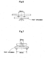
- FIG. 6 shows a test example with respect to the transverse strength (three-point bending).
- FIG. 7 shows a test example with respect to the fatigue strength (four-point bending).
- FIG. 8 shows a relation of a depth from the surface of the cam ring and hardness (load of 2N).
- the same measurement was performed with respect to the cam ring 41 of a comparative example.
- the comparative example was manufactured under basically the same conditions as the embodiment, in which a consolidation body made of the same metal powder as the embodiment was sintered, carburization quenched, and tempered, and a graphite powder was not used.
- the sintered density of the cam ring of the comparative example is 7.2 g/cm 3
- the sintered density of the cam ring of the embodiment is 7.4 g/cm 3
- the cam ring of the embodiment is highly densified and has a very dense structure, and accordingly the embodiment can totally enhance strength, toughness and abrasion resistance.
- the hardness of the cam ring according to the comparative example is about Hv800 when the depth is around 0.1 to 0.2 mm. Even though the depth is greater, the hardness was about Hv700.
- the embodiment has hardness (Hv700 to 800) which is almost equivalent to the hardness of the comparative example, that is, the abrasion resistance at the surface is secured.
- the embodiment has hardness of about Hv450 to 500, which is much lower than the hardness of the comparative example, that is, toughness is secured.
- the carburizer since the high densification of the sintered alloy is promoted, even though it is difficult for the carburizer to penetrate into the sintered alloy, the surface hardness is kept high, and accordingly the abrasion resistance at the surface can be secured. Moreover, the carburizer can be restricted from penetrating into the sintered alloy, and accordingly the increase in the internal hardness of the sintered alloy can be restricted, thereby easily securing toughness.
- the sintered alloy is heated in a gas carburization atmosphere, and then is put into oil (60 °C) to be quenched, however the manufacturing method is not limited thereto.
- the sintered alloy may be quenched by water cooling.
- nickel quantity / molybdenum quantity nickel quantity / molybdenum quantity
- the mass ratio for example, the amount of nickel may be 4 to 3 %, and the amount of molybdenum may be 0.5 %.
- An iron-base sintered part formed by sintering a consolidation body made of a raw mixture powder of an iron-nickel-molybdenum-based metal powder and a carbon-based powder and carburization quenching the sintered consolidation body, and having an iron-nickel-molybdenum-carbon-based carburization quenched structure having density of 7.25 g/cm 3 or more.
- the present invention can be applied to an actuator comprising an iron-base sintered part, a movable element (rotor or the like) and a fixed element (cam ring or the like) formed by the sintered part.
Landscapes
- Engineering & Computer Science (AREA)
- Mechanical Engineering (AREA)
- Chemical & Material Sciences (AREA)
- Materials Engineering (AREA)
- Metallurgy (AREA)
- Organic Chemistry (AREA)
- General Engineering & Computer Science (AREA)
- Manufacturing & Machinery (AREA)
- Powder Metallurgy (AREA)
- Rotary Pumps (AREA)
Claims (9)
- Aktuator (2), der umfasst:ein Gehäuse (3), das eine Betriebskammer (30) aufweist;ein fixiertes Element (4), das in der Betriebskammer (30) montiert ist; undein bewegbares Element (5), um durch eine Antriebsquelle angetrieben zu werden,wobei das bewegbare Element (5) und das fixierte Element (4) durch ein Eisen-basiertes gesintertes Bauteil gebildet sind, das umfasst:eine Aufkohlungsquenchte Struktur, die durch eine Eisen-Nickel-Molybdän-Kohlenstoff-basierte gesinterte Legierung gebildet ist, wobei die Aufkohlungsquenchte Struktur eine Dichte von 7,25 g/cm3 oder mehr aufweist, des Weiterenwobei, wenn das Eisen-basierte gesinterte Bauteil, das das bewegbare Element (5) bildet, auf 100% bezüglich eines Massen-% festgesetzt wird, das Eisen-basierte gesinterte Bauteil, das das bewegbare Element (5) bildet, hauptsächlich aus Nickel von 0,5 bis 5,5%, Molybdän 0,1 bis 1,0%, Kupfer 0,5 bis 2,0%, Kohlenstoff 0,1 bis 0,8% und einem Restbetrag, der im Wesentlichen Eisen und unvermeidbare Verunreinigungen enthält, besteht, undwobei, wenn das Eisen-basierte gesinterte Bauteil, das das fixierte Element (4) bildet, auf 100% bezüglich eines Massen-% festgesetzt wird, das Eisen-basierte gesinterte Bauteil, das das fixierte Element (4) bildet, Nickel von 0,5 bis 5,0%, Molybdän 0,5 bis 1,5%, Kupfer von 0 bis 2,0%, Kohlenstoff 0,1 bis 0,8% und einen Restbetrag, der grundsätzlich Eisen und unvermeidbare Verunreinigungen enthält, umfasst,wobei das bewegbare Element (5) in Kontakt mit zumindest einem Abschnitt des fixierenden Elements (4) bewegt wird undein Massenverhältnis (Ni-Gehalt in dem bewegbaren Element (5)/Ni-Gehalt in dem fixierten Element (4)) in dem Bereich von 0,8 bis 3 ist.
- Aktuator (2) gemäß Anspruch 1, wobei die Dichte in dem Bereich von 7,25 g/cm3 bis 7,5 g/cm3 ist.
- Aktuator (2) gemäß Anspruch 1, wobei die Menge an Nickel 3 bis 4% bezüglich dem Massen-% ist.
- Aktuator (2) nach Anspruch 1, wobei das fixierte Element (4) eine Nocke (41) ist, die eine ringförmige Nockenoberfläche (40) aufweist, und
das bewegbare Element (5) einen Rotor (51), der durch die Nockenoberfläche (40) mit einem Spalt dazwischen umgeben ist und einem Schlitz (50) auf einem äußeren peripheren Abschnitt davon aufweist, und eine Lamelle (53), die vorwärts/rückwärts bewegbar in dem Spalt (50) des Rotors (51) eingepasst ist und einen vorderen Endabschnitt zum Gleiten auf der Nockenoberfläche (40) der Nocke (41) aufweist, beinhaltet. - Verfahren zur Herstellung des Aktuators (2) nach einem der Ansprüche 1 bis 4, das Verfahren umfasst:einen Formprozess des Ladens eines Rohmaterialpulvers aus einem Eisen-Nickel-Molybdän-basierten Metallpulver und einem Kohlenstoff-basierten Pulver in eine Vertiefung (10A, 10B) einer Gussform (1A, 1B) und Verdichten des Rohpulvers in der Vertiefung (10A, 10B), um einen verfestigten Körper zu bilden;einen Sinterprozess des Sintern des verfestigten Körpers bei einer Sintertemperatur, um eine gesinterte Legierung zu bilden; undeinen Aufkohlungsquenchprozess des Erwärmens der gesinterten Legierung in einer Aufkohlungsatmosphäre und des Quenchens der erwärmten Legierung.
- Verfahren nach Anspruch 5, wobei das Rohpulver eine Zusammensetzung aufweist, sodass, wenn das Metallpulver auf 100% bezüglich eines Massen-% festgesetzt wird, das Kohlenstoff-basierte Pulver mit 0,1 bis 0,5% zugegeben wird.
- Verfahren nach Anspruch 5 oder 6, das vor dem Formprozess ferner den Prozess des Aufbringens eines langkettigen Fettsäure-basierten Gleitmittels auf eine Vertiefungsformoberfläche (11A, 11B) der Gussform (1A, 1B), und/oder den Prozess des Zugebens eines langkettigen Fettsäure-basierten Gleitmittels in das Rohpulver umfasst.
- Verfahren nach Anspruch 7, wobei das langkettige Fettsäure-basierte Gleitmittel zumindest ein Material als ein Basismaterial verwendet, das aus der Gruppe ausgewählt ist, die aus Lithiumstearat und Calciumstearat besteht.
- Verfahren nach einem der Ansprüche 5 bis 8, wobei der Formprozess das Erwärmen der Gussform und/oder des Rohpulvers auf 100 bis 250°C beinhaltet.
Applications Claiming Priority (2)
| Application Number | Priority Date | Filing Date | Title |
|---|---|---|---|
| JP2005331781A JP5066803B2 (ja) | 2005-11-16 | 2005-11-16 | アクチュエータ |
| PCT/JP2006/323262 WO2007058370A1 (ja) | 2005-11-16 | 2006-11-15 | 鉄系焼結部品、鉄系焼結部品の製造方法、アクチェエータ |
Publications (3)
| Publication Number | Publication Date |
|---|---|
| EP1950318A1 EP1950318A1 (de) | 2008-07-30 |
| EP1950318A4 EP1950318A4 (de) | 2013-05-15 |
| EP1950318B1 true EP1950318B1 (de) | 2015-04-08 |
Family
ID=38048748
Family Applications (1)
| Application Number | Title | Priority Date | Filing Date |
|---|---|---|---|
| EP06833103.2A Ceased EP1950318B1 (de) | 2005-11-16 | 2006-11-15 | Gesinterte aktuatoren auf eisenbasis und ihre herstellung |
Country Status (4)
| Country | Link |
|---|---|
| US (1) | US8491695B2 (de) |
| EP (1) | EP1950318B1 (de) |
| JP (1) | JP5066803B2 (de) |
| WO (1) | WO2007058370A1 (de) |
Families Citing this family (12)
| Publication number | Priority date | Publication date | Assignee | Title |
|---|---|---|---|---|
| US10123803B2 (en) | 2007-10-17 | 2018-11-13 | Covidien Lp | Methods of managing neurovascular obstructions |
| US8356657B2 (en) * | 2007-12-19 | 2013-01-22 | Teledyne Scientific & Imaging, Llc | Heat pipe system |
| JP5062487B2 (ja) * | 2008-06-10 | 2012-10-31 | 株式会社ジェイテクト | オイルポンプ |
| US8172561B2 (en) * | 2008-06-06 | 2012-05-08 | Jtekt Corporation | Metal part and method of manufacturing metal part |
| EA019753B1 (ru) * | 2008-07-03 | 2014-06-30 | ЭйчАДи КОПЭРЕЙШН | Реактор, устройство и способ проведения гетерогенного катализа |
| JP5765654B2 (ja) * | 2011-09-06 | 2015-08-19 | 住友電工焼結合金株式会社 | 焼結部品の製造方法 |
| DE102013001246A1 (de) | 2013-01-25 | 2014-07-31 | Gkn Sinter Metals Holding Gmbh | Verfahren zur Herstellung eines Flügels für eine Flügelzellenpumpe, Flügel für eine Flügelzellenpumpe sowie Flügelzellenpumpe |
| CN109396417B (zh) * | 2018-11-14 | 2021-11-19 | 连云港东睦新材料有限公司 | 一种变排量机油泵用内外转子的生产工艺 |
| JP7293101B2 (ja) * | 2019-12-17 | 2023-06-19 | ミネベアミツミ株式会社 | 把持装置 |
| JP2021094656A (ja) * | 2019-12-17 | 2021-06-24 | ミネベアミツミ株式会社 | 把持装置 |
| CN113046650A (zh) * | 2021-02-07 | 2021-06-29 | 浙江吉利控股集团有限公司 | 一种气门导管材料及气门导管的制备方法 |
| KR20250054328A (ko) * | 2023-10-16 | 2025-04-23 | 현대자동차주식회사 | 차량 진공펌프용 캠링 및 플레이트 모듈, 및 이의 제조방법 |
Family Cites Families (15)
| Publication number | Priority date | Publication date | Assignee | Title |
|---|---|---|---|---|
| JPS5027881B1 (de) * | 1970-01-15 | 1975-09-11 | ||
| JPS5230924B2 (de) * | 1972-04-06 | 1977-08-11 | ||
| JPH0676649B2 (ja) * | 1986-02-13 | 1994-09-28 | 三菱マテリアル株式会社 | オイルモ−タ用焼結トロコイドロ−タ |
| JPH0578712A (ja) * | 1991-09-25 | 1993-03-30 | Showa Mfg Co Ltd | 焼結部品の製造方法 |
| JPH0790513A (ja) | 1993-09-13 | 1995-04-04 | Mitsubishi Materials Corp | 耐摩耗性のすぐれたベーンポンプ装置の鉛含浸Fe基焼結合金製ベーン部材 |
| JP3314596B2 (ja) * | 1995-10-24 | 2002-08-12 | 三菱マテリアル株式会社 | 疲労強度に優れた鉄基焼結合金 |
| JP3462378B2 (ja) * | 1997-11-07 | 2003-11-05 | 日立粉末冶金株式会社 | 粉末冶金における粉末成形方法 |
| JP4228547B2 (ja) * | 2000-03-28 | 2009-02-25 | Jfeスチール株式会社 | 金型潤滑用潤滑剤および高密度鉄基粉末成形体の製造方法 |
| JP4702758B2 (ja) * | 2000-04-11 | 2011-06-15 | 日立粉末冶金株式会社 | サイレントチェーン用焼結スプロケットおよびその製造方法 |
| US6514307B2 (en) * | 2000-08-31 | 2003-02-04 | Kawasaki Steel Corporation | Iron-based sintered powder metal body, manufacturing method thereof and manufacturing method of iron-based sintered component with high strength and high density |
| EP1273769A3 (de) * | 2001-07-03 | 2003-10-15 | Nissan Motor Co., Ltd. | Nocken für eine gebaute Nockewelle |
| JP4166041B2 (ja) * | 2002-06-03 | 2008-10-15 | 株式会社椿本チエイン | 焼結スプロケット及びその製造方法 |
| JP4301507B2 (ja) * | 2003-07-22 | 2009-07-22 | 日産自動車株式会社 | サイレントチェーン用焼結スプロケットおよびその製造方法 |
| JP4278147B2 (ja) | 2003-11-12 | 2009-06-10 | 株式会社豊田中央研究所 | 磁心用粉末、圧粉磁心およびそれらの製造方法 |
| JP2006046283A (ja) * | 2004-08-09 | 2006-02-16 | Hitachi Ltd | 内接式歯車ポンプ |
-
2005
- 2005-11-16 JP JP2005331781A patent/JP5066803B2/ja not_active Expired - Fee Related
-
2006
- 2006-11-15 US US12/093,373 patent/US8491695B2/en not_active Expired - Fee Related
- 2006-11-15 EP EP06833103.2A patent/EP1950318B1/de not_active Ceased
- 2006-11-15 WO PCT/JP2006/323262 patent/WO2007058370A1/ja not_active Ceased
Also Published As
| Publication number | Publication date |
|---|---|
| JP2007138226A (ja) | 2007-06-07 |
| EP1950318A4 (de) | 2013-05-15 |
| EP1950318A1 (de) | 2008-07-30 |
| WO2007058370A1 (ja) | 2007-05-24 |
| US20090114046A1 (en) | 2009-05-07 |
| US8491695B2 (en) | 2013-07-23 |
| JP5066803B2 (ja) | 2012-11-07 |
Similar Documents
| Publication | Publication Date | Title |
|---|---|---|
| KR100476899B1 (ko) | 분말 금속 부품, 금속 분말 혼합물 및 분말 금속 부품을 제조하는 공정 | |
| JP5992402B2 (ja) | 窒化焼結コンポーネントの製造方法 | |
| EP0015520B1 (de) | Verfahren zur Herstellung von Ventilstösseln | |
| JP4789837B2 (ja) | 鉄系焼結体及びその製造方法 | |
| KR101160690B1 (ko) | 분말 금속 밸브 시트 인서트 | |
| US8491695B2 (en) | Iron-base sintered part, manufacturing method of iron-base sintered part and actuator | |
| EP1500714B1 (de) | Verfahren zur herstelung eines gesinterten Zahnrads für lärmgedämpfte Zahnkette | |
| US4861372A (en) | Roller in rotary compressor and method for producing the same | |
| US4904302A (en) | Roller in rotary compressor and method for producing the same | |
| JP3736838B2 (ja) | メカニカルヒューズおよびその製造方法 | |
| EP3296418B1 (de) | Herstellungsverfahren für verschleissfeste gesinterte legierung auf eisenbasis sowie verschleissfeste gesinterte legierung auf eisenbasis | |
| CN101506398B (zh) | 高碳表面致密化烧结钢产品及其制造方法 | |
| JP2001295915A (ja) | サイレントチェーン用焼結スプロケットおよびその製造方法 | |
| JP3869620B2 (ja) | 合金鋼粉成形素材と合金鋼粉加工体及び合金鋼粉成形素材の製造方法 | |
| US7041149B2 (en) | Sintered sprocket for silent chain and production method therefor | |
| CN104884659B (zh) | 高疲劳强度烧结体用预合金型钢粉和渗碳淬火材 | |
| JP3966471B2 (ja) | メカニカルヒューズおよびその製造方法 | |
| JP2023152727A (ja) | 内燃機関用鉄基焼結合金製バルブシートおよびその製造方法 | |
| JP2023152728A (ja) | 内燃機関用鉄基焼結合金製バルブシートおよびその製造方法 | |
| JP2013173961A (ja) | 鉄基焼結合金製バルブシート | |
| JP4746934B2 (ja) | 鍛造用金型及びその製造方法 | |
| JPH03219057A (ja) | 自己潤滑性焼結摺動材とその製造方法 | |
| JP2020139193A (ja) | 機械部品およびその製造方法 | |
| GB2446245A (en) | Sintered sliding member | |
| Dowson | Cost reduction through innovative powder engineering |
Legal Events
| Date | Code | Title | Description |
|---|---|---|---|
| PUAI | Public reference made under article 153(3) epc to a published international application that has entered the european phase |
Free format text: ORIGINAL CODE: 0009012 |
|
| 17P | Request for examination filed |
Effective date: 20080430 |
|
| AK | Designated contracting states |
Kind code of ref document: A1 Designated state(s): DE FR |
|
| RBV | Designated contracting states (corrected) |
Designated state(s): DE FR |
|
| DAX | Request for extension of the european patent (deleted) | ||
| A4 | Supplementary search report drawn up and despatched |
Effective date: 20130417 |
|
| RIC1 | Information provided on ipc code assigned before grant |
Ipc: B22F 5/00 20060101ALI20130411BHEP Ipc: B22F 3/02 20060101ALI20130411BHEP Ipc: B22F 3/24 20060101ALI20130411BHEP Ipc: F04C 2/344 20060101ALI20130411BHEP Ipc: C22C 38/00 20060101AFI20130411BHEP Ipc: B22F 5/08 20060101ALI20130411BHEP |
|
| 17Q | First examination report despatched |
Effective date: 20131202 |
|
| GRAP | Despatch of communication of intention to grant a patent |
Free format text: ORIGINAL CODE: EPIDOSNIGR1 |
|
| INTG | Intention to grant announced |
Effective date: 20141105 |
|
| GRAS | Grant fee paid |
Free format text: ORIGINAL CODE: EPIDOSNIGR3 |
|
| GRAA | (expected) grant |
Free format text: ORIGINAL CODE: 0009210 |
|
| AK | Designated contracting states |
Kind code of ref document: B1 Designated state(s): DE FR |
|
| REG | Reference to a national code |
Ref country code: DE Ref legal event code: R096 Ref document number: 602006045076 Country of ref document: DE Effective date: 20150521 |
|
| REG | Reference to a national code |
Ref country code: FR Ref legal event code: PLFP Year of fee payment: 10 |
|
| REG | Reference to a national code |
Ref country code: DE Ref legal event code: R097 Ref document number: 602006045076 Country of ref document: DE |
|
| PLBE | No opposition filed within time limit |
Free format text: ORIGINAL CODE: 0009261 |
|
| STAA | Information on the status of an ep patent application or granted ep patent |
Free format text: STATUS: NO OPPOSITION FILED WITHIN TIME LIMIT |
|
| 26N | No opposition filed |
Effective date: 20160111 |
|
| REG | Reference to a national code |
Ref country code: FR Ref legal event code: PLFP Year of fee payment: 11 |
|
| REG | Reference to a national code |
Ref country code: FR Ref legal event code: PLFP Year of fee payment: 12 |
|
| PGFP | Annual fee paid to national office [announced via postgrant information from national office to epo] |
Ref country code: FR Payment date: 20171012 Year of fee payment: 12 Ref country code: DE Payment date: 20171108 Year of fee payment: 12 |
|
| REG | Reference to a national code |
Ref country code: DE Ref legal event code: R119 Ref document number: 602006045076 Country of ref document: DE |
|
| PG25 | Lapsed in a contracting state [announced via postgrant information from national office to epo] |
Ref country code: DE Free format text: LAPSE BECAUSE OF NON-PAYMENT OF DUE FEES Effective date: 20190601 Ref country code: FR Free format text: LAPSE BECAUSE OF NON-PAYMENT OF DUE FEES Effective date: 20181130 |