EP1947742A1 - Connecteur - Google Patents
Connecteur Download PDFInfo
- Publication number
- EP1947742A1 EP1947742A1 EP06797229A EP06797229A EP1947742A1 EP 1947742 A1 EP1947742 A1 EP 1947742A1 EP 06797229 A EP06797229 A EP 06797229A EP 06797229 A EP06797229 A EP 06797229A EP 1947742 A1 EP1947742 A1 EP 1947742A1
- Authority
- EP
- European Patent Office
- Prior art keywords
- cover
- connector
- housing body
- mold
- end portion
- Prior art date
- Legal status (The legal status is an assumption and is not a legal conclusion. Google has not performed a legal analysis and makes no representation as to the accuracy of the status listed.)
- Withdrawn
Links
- 238000005476 soldering Methods 0.000 claims abstract description 9
- 238000003780 insertion Methods 0.000 description 7
- 230000037431 insertion Effects 0.000 description 7
- 238000010276 construction Methods 0.000 description 6
- 238000012986 modification Methods 0.000 description 2
- 230000004048 modification Effects 0.000 description 2
- 230000002093 peripheral effect Effects 0.000 description 2
- 206010016275 Fear Diseases 0.000 description 1
- 230000002708 enhancing effect Effects 0.000 description 1
Images


Classifications
-
- H—ELECTRICITY
- H01—ELECTRIC ELEMENTS
- H01R—ELECTRICALLY-CONDUCTIVE CONNECTIONS; STRUCTURAL ASSOCIATIONS OF A PLURALITY OF MUTUALLY-INSULATED ELECTRICAL CONNECTING ELEMENTS; COUPLING DEVICES; CURRENT COLLECTORS
- H01R13/00—Details of coupling devices of the kinds covered by groups H01R12/70 or H01R24/00 - H01R33/00
- H01R13/46—Bases; Cases
- H01R13/516—Means for holding or embracing insulating body, e.g. casing, hoods
-
- H—ELECTRICITY
- H01—ELECTRIC ELEMENTS
- H01R—ELECTRICALLY-CONDUCTIVE CONNECTIONS; STRUCTURAL ASSOCIATIONS OF A PLURALITY OF MUTUALLY-INSULATED ELECTRICAL CONNECTING ELEMENTS; COUPLING DEVICES; CURRENT COLLECTORS
- H01R12/00—Structural associations of a plurality of mutually-insulated electrical connecting elements, specially adapted for printed circuits, e.g. printed circuit boards [PCB], flat or ribbon cables, or like generally planar structures, e.g. terminal strips, terminal blocks; Coupling devices specially adapted for printed circuits, flat or ribbon cables, or like generally planar structures; Terminals specially adapted for contact with, or insertion into, printed circuits, flat or ribbon cables, or like generally planar structures
- H01R12/70—Coupling devices
- H01R12/77—Coupling devices for flexible printed circuits, flat or ribbon cables or like structures
- H01R12/79—Coupling devices for flexible printed circuits, flat or ribbon cables or like structures connecting to rigid printed circuits or like structures
-
- H—ELECTRICITY
- H01—ELECTRIC ELEMENTS
- H01R—ELECTRICALLY-CONDUCTIVE CONNECTIONS; STRUCTURAL ASSOCIATIONS OF A PLURALITY OF MUTUALLY-INSULATED ELECTRICAL CONNECTING ELEMENTS; COUPLING DEVICES; CURRENT COLLECTORS
- H01R13/00—Details of coupling devices of the kinds covered by groups H01R12/70 or H01R24/00 - H01R33/00
- H01R13/44—Means for preventing access to live contacts
- H01R13/447—Shutter or cover plate
Definitions
- This invention relates to a connector.
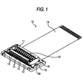
- FIG. 1 denotes a connector
- a number of contact pins 3 are fixed in parallel rows to left and right opposite side portions (upper and lower portions in Fig. 1 ) of a mold 2 of the connector 1, and are arranged to be exposed to the exterior from the left and right opposite sides of the mold 2.
- a circuit board (not shown) such as a flexible board is provided at lower surfaces of contact pins 3, and the contact pins 3 are soldered to the circuit board to be electrically connected thereto.
- the circuit board is connected to other electronic parts.
- an electric connector which is a connector in which a plug connector and a receptacle connector are fitted together and which is constructed such that a resilient force is imparted to contact pins of the receptacle connector so that good contact of the contact pins with contact pins of the plug connector can be maintained (For example, see Japanese Patent Publication No. 11-267.02A )
- a cover-equipped connector having a construction in which a cover is provided at a plug insertion port of the connector, and the intrusion of foreign matters between contact pins of a plug and contact pins of the connector is prevented by the cover so as to prevent electrical short-circuiting and breakage of the connector (For example, see Japanese Patent Publication No. 10-340753A ).
- the above-mentioned conventional connector is constructed such that the plug or the like is connected to the connector so as to electrically connect the electronic parts electrically connected to the plug to the electronic parts connected to the connector.
- the contact pins of the connector are fixed to the mold, and also are connected to terminals of the circuit board by soldering or the like.
- the contact pins of the connector are soldered in such a manner that the contact pins are exposed to the exterior, and therefore may be damaged by an external impact, and besides the contact pins may be subjected to short-circuiting by the intrusion of foreign matters, and therefore this has been the cause of a degraded quality.
- a connector including:
- the first end portion of the contact pin which is adapted to be subjected to soldering is covered with the cover body, and therefore an external impact against the contact pin is prevented by the cover body, and also the intrusion of foreign matters is prevented.
- the cover body may include a first cover supporting the first end portion of the contact pin and a second cover covering the first end portion of the contact pin. With this construction, the cover body can be easily mounted on the housing body.
- the housing body may have a groove opened at a bottom face and a first side face thereof, and the first cover may be inserted into the groove from the first side face. With this construction, the first cover can be easily mounted on the housing body by inserting it into the groove from the first side face of the housing body.
- the connector may include a flexible circuit board having a terminal adapted to be electrically connected to the first end portion of the contact pin by the soldering, and inserted between the housing body and the first cover from a second side face opposite to the first side face.
- the second cover may be a frame-shaped member adapted to surround an outer periphery of the housing body. With this construction, the second cover is formed into the square frame-shape, and therefore the second cover covers the first end portion of the contact pin exposed to the exterior of the housing body, and also a plug insertion portion or a board insertion portion of the connector is exposed from a central portion of the second cover.
- Fig. 1 shows one embodiment of a connector 10 the present invention, and is used in a car audio equipment or the like.
- a central portion of a mold 11 is projected, and further a groove is formed in a central portion of this projected portion to form an insertion port 12 to which other circuit board is adapted to be attached.
- Contact pins 13 are fixed to the mold 11 in left-right opposed relation, and further a flexible board 14 is inserted into the mold 11. Then, as shown in Fig. 2 and Fig. 3 , distal end portions of the contact pins 13 are fixed by soldering to terminals 15 of the flexible board 14, respectively.
- the contact pins 13 are curved inwardly at a central portion of the insertion port 12, and extend laterally upwardly, and then are curved inwardly, and are bent laterally at their lower portions, so that the distal end portions of the contact pins 13 are exposed to the exterior of the mold 11.
- the upper side of the externally-exposed portions of the contact pins 13 disposed at an edge portion around the outer periphery of the insertion port 12 and a lower surface of the connector 10 are covered with a cover 16.
- the cover 16 is composed of an upper cover 17 and a lower cover 18.
- the upper cover 17 is formed into a square frame-shape. Further, the upper cover 17 is formed into a cxoss-sectionally L-shape, and is so constructed as to cover the upper side of the contact pins 13 exposed from the mold 11. Convex portions 19 formed respectively at opposite side portions (left and right in Fig. 2 ) of the mold 11 can be fitted respectively in recesses 20. formed respectively in opposite side portions of the upper cover 17, thereby fixing the upper cover 17 to the mold 11.
- the grooves 23 in the mold 11 are formed to extend from a rear portion to a middle portion of the mold 11 in the forward-rearward direction, and by inserting the sliding portions 21 of the lower cover 18 respectively into the grooves 23 from the rear side of the connector 10, the lower cover 18 is attached to the mold 11. Then, a distal end portion of the lower cover 18 abuts against rear end portions of the grooves 23, so that the forward movement of the lower cover 18 is limited.
- the flexible board 14 is inserted to be disposed at the lower surface of the mold 11 and also on the upper surface of the lower cover 18.
- the flexible board 14 is inserted from the front side (the right side in Fig. 1 ), and the contact pins 13 are soldered respectively to the terminals 15 of the flexible board 14, and the flexible board 14 extends forwardly from the connector 10.
- the flexible board 14 When assembling the connector 10, the flexible board 14 is inserted from the front side to be disposed at the lower surface of the mold 11 having the contact pins 13 mounted thereon, and the terminals 15 of the flexible board 14 are fixed by soldering to the distal end portions of the contact pins 13, respectively. Then, the lower cover 18 is pushed in from the outer side face of the recessed portion 22 of the mold 11. At this time, the sliding portions 21 slide respectively along the grooves 23 of the recessed portion 22, and the sliding portions 21 abut against the rear end portions of the grooves 23, respectively, so that the forward movement of the lower cover 18 is limited, and the lower cover 18 is attached to the mold 11. When attaching the lower cover 18, the flexible board 14 will not prevent the attaching of the lower cover 18 since the flexible board 14 extends forwardly, and the lower cover 18 can be easily mounted on the mold 11.
- the upper cover 17 By attaching the upper cover 17 to the peripheral edge portion of the mold 11 from the upper side of the mold 11, the upper cover 17 is fixed to the mold 11. At this time, the lower end of the end edge of the upper cover 17 abuts against the peripheral edge portion of the lower cover 18 as shown in Fig. 4 , thereby preventing the movement of the lower cover 18, and therefore the lower cover 18 is stably fixed to the mold 11.
- the connected portions between the contact pins 13 and the terminals 15 of the flexible board 14 are covered with the cover 16, and therefore fears for damage of the connection between the contact pins 13 and the terminals 15 due to an external impact, etc., can be eliminated. Furthermore, the intrusion of foreign matters can be prevented by the cover 16, and the electrical short-circuiting of the contact pins 13 is prevented, thereby enhancing the quality of the connector 10.
Landscapes
- Coupling Device And Connection With Printed Circuit (AREA)
- Connector Housings Or Holding Contact Members (AREA)
Applications Claiming Priority (2)
| Application Number | Priority Date | Filing Date | Title |
|---|---|---|---|
| JP2005316231A JP4600245B2 (ja) | 2005-10-31 | 2005-10-31 | コネクタ |
| PCT/JP2006/317269 WO2007052405A1 (fr) | 2005-10-31 | 2006-08-31 | Connecteur |
Publications (2)
| Publication Number | Publication Date |
|---|---|
| EP1947742A1 true EP1947742A1 (fr) | 2008-07-23 |
| EP1947742A4 EP1947742A4 (fr) | 2011-10-19 |
Family
ID=38005565
Family Applications (1)
| Application Number | Title | Priority Date | Filing Date |
|---|---|---|---|
| EP06797229A Withdrawn EP1947742A4 (fr) | 2005-10-31 | 2006-08-31 | Connecteur |
Country Status (4)
| Country | Link |
|---|---|
| US (1) | US7896688B2 (fr) |
| EP (1) | EP1947742A4 (fr) |
| JP (1) | JP4600245B2 (fr) |
| WO (1) | WO2007052405A1 (fr) |
Families Citing this family (8)
| Publication number | Priority date | Publication date | Assignee | Title |
|---|---|---|---|---|
| KR101559603B1 (ko) | 2008-02-07 | 2015-10-12 | 미쓰비시 가가꾸 가부시키가이샤 | 반도체 발광 장치, 백라이트, 컬러 화상 표시 장치, 및 그들에 사용하는 형광체 |
| US8400177B2 (en) * | 2008-09-01 | 2013-03-19 | Chimei Innolux Corporation | Device and method for testing display panel |
| US8197261B2 (en) * | 2010-05-10 | 2012-06-12 | Hsing Chau Industrial Co., Ltd. | Telecommunication connector having a flexible circuit board wound across a support member and ends being bent into fixing plates coupled to two rows of terminals |
| TWM450838U (zh) * | 2012-10-22 | 2013-04-11 | Bing Xu Prec Co Ltd | 軟性排線電連接器固定結構 |
| JP2016501437A (ja) * | 2012-12-19 | 2016-01-18 | スリーエム イノベイティブ プロパティズ カンパニー | ケーブル対基板コネクタ |
| JP6005575B2 (ja) * | 2013-04-11 | 2016-10-12 | 日本航空電子工業株式会社 | コネクタ |
| JP6840559B2 (ja) * | 2017-02-10 | 2021-03-10 | 日本航空電子工業株式会社 | コネクタ |
| CN109411934B (zh) * | 2017-08-16 | 2021-11-19 | 富士康(昆山)电脑接插件有限公司 | 电连接器 |
Citations (2)
| Publication number | Priority date | Publication date | Assignee | Title |
|---|---|---|---|---|
| US20040229491A1 (en) * | 2003-05-13 | 2004-11-18 | Japan Aviation Electronics Industry, Limited | Electrical connector having a mechanism for supplementing spring characteristics of a contact |
| WO2005083850A1 (fr) * | 2004-03-01 | 2005-09-09 | Matsushita Electric Works, Ltd. | Assemblage de connecteur et procede de fabrication d'assemblage de connecteur |
Family Cites Families (35)
| Publication number | Priority date | Publication date | Assignee | Title |
|---|---|---|---|---|
| US3149896A (en) * | 1960-11-04 | 1964-09-22 | Bendix Corp | Electrical connector |
| US3214713A (en) * | 1961-06-30 | 1965-10-26 | Sanders Associates Inc | Flexible printed circuit cable connector |
| US3702982A (en) * | 1971-02-08 | 1972-11-14 | Itt | Flat cable connector |
| US3731254A (en) * | 1971-08-02 | 1973-05-01 | Thomas & Betts Corp | Jumper for interconnecting dual-in-line sockets |
| US3938378A (en) * | 1974-08-26 | 1976-02-17 | The United States Of America As Represented By The Secretary Of The Army | Engine compression testing |
| DE2708566C2 (de) * | 1977-02-28 | 1983-04-14 | Walter 5960 Olpe Grabowski | An die Netzleitung und an geschaltete Leitungen anschließbare, unter Putz zu verlegende Installationsleiste für eine Mehrzahl von im Abstand voneinander zu installierenden Bauteilen |
| US4621305A (en) * | 1984-08-22 | 1986-11-04 | General Motors Corporation | Header connector and attachment |
| US4647133A (en) * | 1985-04-18 | 1987-03-03 | Innovus | Electrical interconnect system |
| US4695106A (en) * | 1985-05-13 | 1987-09-22 | Amp Incorporated | Surface mount, miniature connector |
| US4756940A (en) * | 1986-03-25 | 1988-07-12 | Tektronix, Inc. | Flexible circuit strain relief |
| US4938379A (en) * | 1988-12-23 | 1990-07-03 | Kellner Louis W | Cover for a beverage can |
| US4948378A (en) * | 1989-03-02 | 1990-08-14 | Thomas & Betts Corporation | Waterproof electrical connector assembly |
| JPH067502B2 (ja) * | 1989-05-30 | 1994-01-26 | 菱星電装株式会社 | フラットケーブルコネクタ |
| JPH089901Y2 (ja) * | 1990-08-16 | 1996-03-21 | 株式会社横尾製作所 | フラットケーブル用コネクター |
| JP3016164B2 (ja) * | 1991-06-19 | 2000-03-06 | 日本エー・エム・ピー株式会社 | 可動型コネクタ |
| JP2757601B2 (ja) * | 1991-07-31 | 1998-05-25 | 住友電装株式会社 | 分岐接続器 |
| GB2261558B (en) * | 1991-10-31 | 1996-07-10 | Sumitomo Wiring Systems | A connector assembly |
| US5201664A (en) * | 1992-02-12 | 1993-04-13 | Amp Incorporated | Alignment member for use with surface mount contacts |
| US5242311A (en) * | 1993-02-16 | 1993-09-07 | Molex Incorporated | Electrical connector header with slip-off positioning cover and method of using same |
| JPH06314581A (ja) * | 1993-04-30 | 1994-11-08 | Matsushita Electric Ind Co Ltd | Fpc用コネクタ |
| JPH07106014A (ja) * | 1993-10-01 | 1995-04-21 | Mitsubishi Cable Ind Ltd | コネクタ |
| US5501612A (en) * | 1994-06-17 | 1996-03-26 | The Whitaker Corporation | Low profile board-to-board electrical connector |
| JP3262198B2 (ja) * | 1995-08-15 | 2002-03-04 | 株式会社アイペックス | コネクタ |
| JPH10340753A (ja) | 1997-06-04 | 1998-12-22 | Hosiden Corp | カバー付コネクタ |
| JP3321035B2 (ja) | 1997-06-27 | 2002-09-03 | 第一電子工業株式会社 | 電気コネクタ |
| JP4168507B2 (ja) * | 1999-01-29 | 2008-10-22 | モレックス インコーポレーテッド | 電気コネクタ |
| US6394816B1 (en) * | 1999-10-01 | 2002-05-28 | Yazaki Corporation | Connecting device for flat circuit |
| JP2002025667A (ja) * | 2000-07-11 | 2002-01-25 | Hirose Electric Co Ltd | フラットケーブル用コネクタ |
| JP2003004463A (ja) * | 2001-06-19 | 2003-01-08 | Kenwood Corp | ナビゲーション装置、及びプログラム |
| US6402532B1 (en) * | 2001-06-22 | 2002-06-11 | Jess -Link Products Co., Ltd. | Pressing bar for connecting legs of connectors |
| US6447329B1 (en) * | 2001-10-19 | 2002-09-10 | All Best Electronics Co., Ltd. | Connector |
| US7381064B2 (en) * | 2003-08-26 | 2008-06-03 | Methode Electronics, Inc. | Flexible flat cable termination structure for a clockspring |
| US6830478B1 (en) * | 2003-12-10 | 2004-12-14 | Hon Hai Precision Ind. Co., Ltd. | Micro coaxial connector assembly with latching means |
| JP2006244731A (ja) * | 2005-02-28 | 2006-09-14 | Molex Inc | ターミナルおよびこのターミナルを用いたコネクタ |
| CN201178146Y (zh) * | 2008-03-05 | 2009-01-07 | 富士康(昆山)电脑接插件有限公司 | 电连接器及电连接器组件 |
-
2005
- 2005-10-31 JP JP2005316231A patent/JP4600245B2/ja not_active Expired - Fee Related
-
2006
- 2006-08-31 US US12/092,135 patent/US7896688B2/en not_active Expired - Fee Related
- 2006-08-31 EP EP06797229A patent/EP1947742A4/fr not_active Withdrawn
- 2006-08-31 WO PCT/JP2006/317269 patent/WO2007052405A1/fr active Application Filing
Patent Citations (2)
| Publication number | Priority date | Publication date | Assignee | Title |
|---|---|---|---|---|
| US20040229491A1 (en) * | 2003-05-13 | 2004-11-18 | Japan Aviation Electronics Industry, Limited | Electrical connector having a mechanism for supplementing spring characteristics of a contact |
| WO2005083850A1 (fr) * | 2004-03-01 | 2005-09-09 | Matsushita Electric Works, Ltd. | Assemblage de connecteur et procede de fabrication d'assemblage de connecteur |
Non-Patent Citations (1)
| Title |
|---|
| See also references of WO2007052405A1 * |
Also Published As
| Publication number | Publication date |
|---|---|
| JP4600245B2 (ja) | 2010-12-15 |
| WO2007052405A1 (fr) | 2007-05-10 |
| EP1947742A4 (fr) | 2011-10-19 |
| US20090305566A1 (en) | 2009-12-10 |
| US7896688B2 (en) | 2011-03-01 |
| JP2007123154A (ja) | 2007-05-17 |
Similar Documents
| Publication | Publication Date | Title |
|---|---|---|
| US7896688B2 (en) | Electrical connector with flexible circuit board | |
| US7699663B1 (en) | Electrical connector with improved grounding contact | |
| US7883371B1 (en) | Electrical connector with improved contact footprints | |
| KR101680191B1 (ko) | 커넥터 | |
| JP4368897B2 (ja) | コネクタ | |
| US7614887B1 (en) | Electrical connector with improved contacts | |
| US7422475B2 (en) | Electrical connector | |
| US8506333B2 (en) | Connector assembly having front and rear rows of terminals with differently leveled contacting portions | |
| US8070528B2 (en) | Electrical connector having improved terminals | |
| JP4851510B2 (ja) | 電気コネクタ | |
| US8033861B2 (en) | Electrical connector with improved board lock having elastic portion abutting against optical drive disk | |
| EP3676912B1 (fr) | Prise usb-c avec points de contact de montage en surface | |
| JP2021168234A (ja) | コネクタ | |
| US7413476B2 (en) | Electrical interconnection with mating terminals | |
| US6863546B2 (en) | Cable connector assembly having positioning structure | |
| KR101042120B1 (ko) | 전기 커넥터 | |
| JP4774956B2 (ja) | コネクタ、及びコネクタ用レセプタクル | |
| US20090149078A1 (en) | Connector | |
| TWI720706B (zh) | 線纜連接器組件 | |
| US20160285214A1 (en) | Electric connector assembly mated with a mating connector in two orientations | |
| CN111211432B (zh) | 连接器 | |
| CN113795983B (zh) | 电连接器及电连接器装置 | |
| US20100167590A1 (en) | Contact Assembly, Method for Manufacturing Contact Assembly, and Electrical Connector | |
| US6203341B1 (en) | Cable connector | |
| US6645013B1 (en) | Electronic system and connector used therein |
Legal Events
| Date | Code | Title | Description |
|---|---|---|---|
| PUAI | Public reference made under article 153(3) epc to a published international application that has entered the european phase |
Free format text: ORIGINAL CODE: 0009012 |
|
| 17P | Request for examination filed |
Effective date: 20080429 |
|
| AK | Designated contracting states |
Kind code of ref document: A1 Designated state(s): DE FR |
|
| DAX | Request for extension of the european patent (deleted) | ||
| RBV | Designated contracting states (corrected) |
Designated state(s): DE FR |
|
| A4 | Supplementary search report drawn up and despatched |
Effective date: 20110916 |
|
| RIC1 | Information provided on ipc code assigned before grant |
Ipc: H01R 13/52 20060101AFI20110913BHEP |
|
| GRAP | Despatch of communication of intention to grant a patent |
Free format text: ORIGINAL CODE: EPIDOSNIGR1 |
|
| RIC1 | Information provided on ipc code assigned before grant |
Ipc: H01R 13/516 20060101ALI20130315BHEP Ipc: H01R 13/52 20060101AFI20130315BHEP |
|
| INTG | Intention to grant announced |
Effective date: 20130408 |
|
| STAA | Information on the status of an ep patent application or granted ep patent |
Free format text: STATUS: THE APPLICATION IS DEEMED TO BE WITHDRAWN |
|
| 18D | Application deemed to be withdrawn |
Effective date: 20130820 |