EP1947355B1 - Dispositif de palier pour roue - Google Patents
Dispositif de palier pour roue Download PDFInfo
- Publication number
- EP1947355B1 EP1947355B1 EP06811194.7A EP06811194A EP1947355B1 EP 1947355 B1 EP1947355 B1 EP 1947355B1 EP 06811194 A EP06811194 A EP 06811194A EP 1947355 B1 EP1947355 B1 EP 1947355B1
- Authority
- EP
- European Patent Office
- Prior art keywords
- wheel
- double row
- bearing apparatus
- raceway surface
- vehicle
- Prior art date
- Legal status (The legal status is an assumption and is not a legal conclusion. Google has not performed a legal analysis and makes no representation as to the accuracy of the status listed.)
- Active
Links
- 238000010438 heat treatment Methods 0.000 claims description 10
- 238000004519 manufacturing process Methods 0.000 claims description 2
- 230000007704 transition Effects 0.000 description 6
- 229910052799 carbon Inorganic materials 0.000 description 5
- OKTJSMMVPCPJKN-UHFFFAOYSA-N Carbon Chemical compound [C] OKTJSMMVPCPJKN-UHFFFAOYSA-N 0.000 description 4
- 229910000954 Medium-carbon steel Inorganic materials 0.000 description 4
- 102220097517 rs876659265 Human genes 0.000 description 4
- 239000004519 grease Substances 0.000 description 3
- 238000010791 quenching Methods 0.000 description 3
- 230000000171 quenching effect Effects 0.000 description 3
- 238000005096 rolling process Methods 0.000 description 3
- XLYOFNOQVPJJNP-UHFFFAOYSA-N water Substances O XLYOFNOQVPJJNP-UHFFFAOYSA-N 0.000 description 3
- 238000005452 bending Methods 0.000 description 2
- 230000006698 induction Effects 0.000 description 2
- 230000004048 modification Effects 0.000 description 2
- 238000012986 modification Methods 0.000 description 2
- 230000009467 reduction Effects 0.000 description 2
- 230000032798 delamination Effects 0.000 description 1
- 238000007598 dipping method Methods 0.000 description 1
- 230000000694 effects Effects 0.000 description 1
- 238000005242 forging Methods 0.000 description 1
- 239000000446 fuel Substances 0.000 description 1
- 238000000034 method Methods 0.000 description 1
- 230000002028 premature Effects 0.000 description 1
- 230000008569 process Effects 0.000 description 1
- 238000007789 sealing Methods 0.000 description 1
- 239000000725 suspension Substances 0.000 description 1
Images


Classifications
-
- F—MECHANICAL ENGINEERING; LIGHTING; HEATING; WEAPONS; BLASTING
- F16—ENGINEERING ELEMENTS AND UNITS; GENERAL MEASURES FOR PRODUCING AND MAINTAINING EFFECTIVE FUNCTIONING OF MACHINES OR INSTALLATIONS; THERMAL INSULATION IN GENERAL
- F16C—SHAFTS; FLEXIBLE SHAFTS; ELEMENTS OR CRANKSHAFT MECHANISMS; ROTARY BODIES OTHER THAN GEARING ELEMENTS; BEARINGS
- F16C19/00—Bearings with rolling contact, for exclusively rotary movement
- F16C19/02—Bearings with rolling contact, for exclusively rotary movement with bearing balls essentially of the same size in one or more circular rows
- F16C19/14—Bearings with rolling contact, for exclusively rotary movement with bearing balls essentially of the same size in one or more circular rows for both radial and axial load
- F16C19/18—Bearings with rolling contact, for exclusively rotary movement with bearing balls essentially of the same size in one or more circular rows for both radial and axial load with two or more rows of balls
- F16C19/181—Bearings with rolling contact, for exclusively rotary movement with bearing balls essentially of the same size in one or more circular rows for both radial and axial load with two or more rows of balls with angular contact
- F16C19/183—Bearings with rolling contact, for exclusively rotary movement with bearing balls essentially of the same size in one or more circular rows for both radial and axial load with two or more rows of balls with angular contact with two rows at opposite angles
- F16C19/184—Bearings with rolling contact, for exclusively rotary movement with bearing balls essentially of the same size in one or more circular rows for both radial and axial load with two or more rows of balls with angular contact with two rows at opposite angles in O-arrangement
- F16C19/186—Bearings with rolling contact, for exclusively rotary movement with bearing balls essentially of the same size in one or more circular rows for both radial and axial load with two or more rows of balls with angular contact with two rows at opposite angles in O-arrangement with three raceways provided integrally on parts other than race rings, e.g. third generation hubs
-
- B—PERFORMING OPERATIONS; TRANSPORTING
- B60—VEHICLES IN GENERAL
- B60B—VEHICLE WHEELS; CASTORS; AXLES FOR WHEELS OR CASTORS; INCREASING WHEEL ADHESION
- B60B27/00—Hubs
- B60B27/0005—Hubs with ball bearings
-
- B—PERFORMING OPERATIONS; TRANSPORTING
- B60—VEHICLES IN GENERAL
- B60B—VEHICLE WHEELS; CASTORS; AXLES FOR WHEELS OR CASTORS; INCREASING WHEEL ADHESION
- B60B27/00—Hubs
- B60B27/0078—Hubs characterised by the fixation of bearings
- B60B27/0084—Hubs characterised by the fixation of bearings caulking to fix inner race
-
- B—PERFORMING OPERATIONS; TRANSPORTING
- B60—VEHICLES IN GENERAL
- B60B—VEHICLE WHEELS; CASTORS; AXLES FOR WHEELS OR CASTORS; INCREASING WHEEL ADHESION
- B60B27/00—Hubs
- B60B27/0094—Hubs one or more of the bearing races are formed by the hub
-
- F—MECHANICAL ENGINEERING; LIGHTING; HEATING; WEAPONS; BLASTING
- F16—ENGINEERING ELEMENTS AND UNITS; GENERAL MEASURES FOR PRODUCING AND MAINTAINING EFFECTIVE FUNCTIONING OF MACHINES OR INSTALLATIONS; THERMAL INSULATION IN GENERAL
- F16C—SHAFTS; FLEXIBLE SHAFTS; ELEMENTS OR CRANKSHAFT MECHANISMS; ROTARY BODIES OTHER THAN GEARING ELEMENTS; BEARINGS
- F16C19/00—Bearings with rolling contact, for exclusively rotary movement
- F16C19/02—Bearings with rolling contact, for exclusively rotary movement with bearing balls essentially of the same size in one or more circular rows
- F16C19/14—Bearings with rolling contact, for exclusively rotary movement with bearing balls essentially of the same size in one or more circular rows for both radial and axial load
- F16C19/18—Bearings with rolling contact, for exclusively rotary movement with bearing balls essentially of the same size in one or more circular rows for both radial and axial load with two or more rows of balls
- F16C19/181—Bearings with rolling contact, for exclusively rotary movement with bearing balls essentially of the same size in one or more circular rows for both radial and axial load with two or more rows of balls with angular contact
- F16C19/183—Bearings with rolling contact, for exclusively rotary movement with bearing balls essentially of the same size in one or more circular rows for both radial and axial load with two or more rows of balls with angular contact with two rows at opposite angles
- F16C19/184—Bearings with rolling contact, for exclusively rotary movement with bearing balls essentially of the same size in one or more circular rows for both radial and axial load with two or more rows of balls with angular contact with two rows at opposite angles in O-arrangement
- F16C19/185—Bearings with rolling contact, for exclusively rotary movement with bearing balls essentially of the same size in one or more circular rows for both radial and axial load with two or more rows of balls with angular contact with two rows at opposite angles in O-arrangement with two raceways provided integrally on a part other than a race ring, e.g. a shaft or housing
-
- F—MECHANICAL ENGINEERING; LIGHTING; HEATING; WEAPONS; BLASTING
- F16—ENGINEERING ELEMENTS AND UNITS; GENERAL MEASURES FOR PRODUCING AND MAINTAINING EFFECTIVE FUNCTIONING OF MACHINES OR INSTALLATIONS; THERMAL INSULATION IN GENERAL
- F16C—SHAFTS; FLEXIBLE SHAFTS; ELEMENTS OR CRANKSHAFT MECHANISMS; ROTARY BODIES OTHER THAN GEARING ELEMENTS; BEARINGS
- F16C33/00—Parts of bearings; Special methods for making bearings or parts thereof
- F16C33/30—Parts of ball or roller bearings
- F16C33/58—Raceways; Race rings
- F16C33/581—Raceways; Race rings integral with other parts, e.g. with housings or machine elements such as shafts or gear wheels
-
- F—MECHANICAL ENGINEERING; LIGHTING; HEATING; WEAPONS; BLASTING
- F16—ENGINEERING ELEMENTS AND UNITS; GENERAL MEASURES FOR PRODUCING AND MAINTAINING EFFECTIVE FUNCTIONING OF MACHINES OR INSTALLATIONS; THERMAL INSULATION IN GENERAL
- F16C—SHAFTS; FLEXIBLE SHAFTS; ELEMENTS OR CRANKSHAFT MECHANISMS; ROTARY BODIES OTHER THAN GEARING ELEMENTS; BEARINGS
- F16C33/00—Parts of bearings; Special methods for making bearings or parts thereof
- F16C33/30—Parts of ball or roller bearings
- F16C33/58—Raceways; Race rings
- F16C33/64—Special methods of manufacture
-
- F—MECHANICAL ENGINEERING; LIGHTING; HEATING; WEAPONS; BLASTING
- F16—ENGINEERING ELEMENTS AND UNITS; GENERAL MEASURES FOR PRODUCING AND MAINTAINING EFFECTIVE FUNCTIONING OF MACHINES OR INSTALLATIONS; THERMAL INSULATION IN GENERAL
- F16C—SHAFTS; FLEXIBLE SHAFTS; ELEMENTS OR CRANKSHAFT MECHANISMS; ROTARY BODIES OTHER THAN GEARING ELEMENTS; BEARINGS
- F16C43/00—Assembling bearings
- F16C43/04—Assembling rolling-contact bearings
- F16C43/06—Placing rolling bodies in cages or bearings
-
- F—MECHANICAL ENGINEERING; LIGHTING; HEATING; WEAPONS; BLASTING
- F16—ENGINEERING ELEMENTS AND UNITS; GENERAL MEASURES FOR PRODUCING AND MAINTAINING EFFECTIVE FUNCTIONING OF MACHINES OR INSTALLATIONS; THERMAL INSULATION IN GENERAL
- F16C—SHAFTS; FLEXIBLE SHAFTS; ELEMENTS OR CRANKSHAFT MECHANISMS; ROTARY BODIES OTHER THAN GEARING ELEMENTS; BEARINGS
- F16C2240/00—Specified values or numerical ranges of parameters; Relations between them
- F16C2240/40—Linear dimensions, e.g. length, radius, thickness, gap
- F16C2240/70—Diameters; Radii
- F16C2240/80—Pitch circle diameters [PCD]
-
- F—MECHANICAL ENGINEERING; LIGHTING; HEATING; WEAPONS; BLASTING
- F16—ENGINEERING ELEMENTS AND UNITS; GENERAL MEASURES FOR PRODUCING AND MAINTAINING EFFECTIVE FUNCTIONING OF MACHINES OR INSTALLATIONS; THERMAL INSULATION IN GENERAL
- F16C—SHAFTS; FLEXIBLE SHAFTS; ELEMENTS OR CRANKSHAFT MECHANISMS; ROTARY BODIES OTHER THAN GEARING ELEMENTS; BEARINGS
- F16C2326/00—Articles relating to transporting
- F16C2326/01—Parts of vehicles in general
- F16C2326/02—Wheel hubs or castors
-
- Y—GENERAL TAGGING OF NEW TECHNOLOGICAL DEVELOPMENTS; GENERAL TAGGING OF CROSS-SECTIONAL TECHNOLOGIES SPANNING OVER SEVERAL SECTIONS OF THE IPC; TECHNICAL SUBJECTS COVERED BY FORMER USPC CROSS-REFERENCE ART COLLECTIONS [XRACs] AND DIGESTS
- Y02—TECHNOLOGIES OR APPLICATIONS FOR MITIGATION OR ADAPTATION AGAINST CLIMATE CHANGE
- Y02T—CLIMATE CHANGE MITIGATION TECHNOLOGIES RELATED TO TRANSPORTATION
- Y02T10/00—Road transport of goods or passengers
- Y02T10/80—Technologies aiming to reduce greenhouse gasses emissions common to all road transportation technologies
- Y02T10/86—Optimisation of rolling resistance, e.g. weight reduction
Definitions
- the present invention relates to a bearing apparatus for freely rotatably supporting a wheel of vehicle, and more particularly to a bearing apparatus for a wheel of vehicle which can improve the rigidity and life of the bearing apparatus.
- the bearing apparatus for a wheel of vehicle is adapted to freely rotatably support a hub wheel for mounting the wheel via a rolling bearing and it is adopted an inner ring rotation type for a driving wheel and both inner ring rotation and outer ring rotation types for a driven wheel.
- a double row angular ball bearing is widely used in such a bearing apparatus from reasons that it has a desirable bearing rigidity, high durability against misalignment and small rotation torque required for fuel consumption.
- the double row angular contact ball bearing has a plurality of balls interposed between a stationary ring and a rotational ring and the balls are contacted with the stationary and rotational rings with being applied a predetermined contact angle.
- the bearing apparatus for a wheel of vehicle is broadly classified to a structure of first generation in which a wheel bearing of double row angular contact ball bearing is fitted between a knuckle forming part of a suspension and a hub wheel, a structure of second generation in which a body mounting flange or a wheel mounting flange is directly formed on the outer circumferential surface of an outer member, a structure of third generation in which one of the inner raceway surfaces is directly formed on the outer circumferential surface of the hub wheel, and a structure of fourth generation in which the inner raceway surfaces are directly formed on the outer circumferential surfaces of the hub wheel and the constant velocity universal joint.
- the bearing apparatus for a wheel of vehicle 50 is formed by a double row angular ball bearing comprising an outer member 51 integrally formed on its outer circumferential surface with a body mounting flange to be mounted on a knuckle (not shown) of a vehicle and on its inner circumferential surface with double row outer raceway surfaces 51a, 51b; an inner member 55 including a hub wheel 52 having a wheel mounting flange 53 integrally formed one end thereof for mounting a wheel (not shown), one inner raceway surface 52a formed on the outer circumferential surface thereof oppositely to one 51a of the double row outer raceway surfaces 51a, 51b, and a cylindrical portion 52b axially extending from the inner raceway surface 52a, and further including an inner ring 54 fitted on the cylindrical portion 52b and formed on its outer circumferential surface with the other inner raceway surface 54a oppositely to the other raceway surface 51b of the double row outer raceway surfaces 51a, 51b; double row balls 56, 57 freely rollably contained between the outer raceway surfaces 51a,
- the inner ring 54 is axially immovably secured by a caulked portion 52c formed by plastically deforming the cylindrical portion 52b of the hub wheel 52 radially outward.
- Seals 60, 61 are mounted in annular openings formed between the outer member 51 and the inner member 55 to prevent leakage of grease contained within the bearing apparatus and entering of rain water or dusts into the bearing apparatus from the outside.
- a pitch circle diameter D1 of the outer side ball group 56 is set larger than a pitch circle diameter D2 of the inner side ball group 57. Accordingly the diameter of the inner raceway surface 52a of the hub wheel 52 is larger than that of the inner raceway surface 54a of the inner ring 54 as well as the outer raceway surface 51a of the outer side of the outer member 51 is larger than that of the outer raceway surface 51b of the inner side of the outer member 51. Also the number of outer side balls 56 is larger than that of the inner side balls 57.
- a stepped portion 62 of the hub wheel 52 is formed between the inner raceway surface 52a of the outer side and the cylindrical portion 52b on which the inner ring 54 is press fitted.
- the presence of the stepped portion 62 (height of step: (D1-D2)/2) causes a problem that the balls 56 of the outer side temporary assembled in the outer raceway surface 51a of the outer member 51 by the cage 58 tends to contact the stepped portion 62 and a counter portion 63 of the inner raceway surface 52a of the hub wheel 52 and thus to be damaged by them during assembly of the bearing apparatus 50.
- an object of the present invention to provide a bearing apparatus for a wheel of vehicle which can solve the antinomic problems of reducing the weight and size of the bearing apparatus and of increasing the rigidity of the bearing apparatus, and also can improve the noise characteristics and the life of the bearing apparatus by preventing generation of damages on balls during assembly of them.
- a double row angular ball bearing apparatus for a wheel of vehicle comprising an outer member formed on its inner circumferential surface with double row outer raceway surfaces; inner members each formed on its outer circumferential surface with double row inner raceway surfaces oppositely arranged to the double row outer raceway surfaces; and double row ball groups freely rollably contained between the outer raceway surfaces and inner raceway surfaces of the inner members and the outer member ,wherein a pitch circle diameter of a ball group of the outer side is larger than a pitch circle diameter of a ball group of the inner side, characterized in that each of corner portions of the outer circumferential surfaces of the inner member is rounded as a smooth circular arc, and that each of corner portions of counter portions of the outer and inner raceway surfaces is rounded as a smooth circular arc and that a counter portion is formed near the bottom of the inner raceway surface of the hub wheel and has a predetermined width and a diameter larger than that of the bottom of said inner raceway surface. (claim 1).
- the pitch circle diameter of the ball group of the outer side is larger than the pitch circle diameter of the ball group of the inner side, and since each of corner portions of the outer circumferential surfaces of the inner member is rounded as a smooth circular arc, it is possible to provide a wheel bearing apparatus for a wheel of vehicle which can suppress generation of the ball damage during assembly of the bearing apparatus and thus can improve the noise characteristics, the life as well as the rigidity of the bearing apparatus.
- each of corner portions of counter portions of the outer and inner raceway surfaces is rounded as a smooth circular arc. This makes it possible to suppress the generation of damaged on the balls during assembly of the bearing apparatus both in a bearing manufacturer and an automobile manufacturer and thus to improve the noise characteristics and the reliability of the bearing apparatus.
- each of corner portions of shoulders of the outer and inner raceway surfaces is rounded as a smooth circular arc (claim 2). This makes it possible to suppress generation of "edge load” even though the oval contacting region rides over shoulders of the raceway surfaces and thus to extend the life of the bearing apparatus.
- each ball is same, and the number of ball group at the outer side is larger than that of a ball group at the inner side (claim 3). This makes it possible to improve both the rigidity and the life of the bearing apparatus.
- the corner portions respectively of the shoulders and the counter portions are ground simultaneously with the inner and outer raceway surface after heat treatment by a formed grinding wheel (claim 7). This makes it possible to form the shoulders and corner portions smoother.
- the inner member comprises a hub wheel having a wheel mounting formed integrally therewith at one end thereof, one inner raceway surface formed on the outer circumferential surface thereof oppositely to one of the double row outer raceway surfaces, and a cylindrical portion axially extending from the inner raceway surface, and further comprises an inner ring fitted on the cylindrical portion and formed on its outer circumferential surface with the other inner raceway surface oppositely to the other raceway surface of the double row outer raceway surfaces; and wherein a substantially conical recess is formed at an outer side end portion of the hub wheel, and the depth of the recess extends to at least near the bottom of the inner raceway surface of the hub wheel so that the outer side end portion of the hub wheel has a substantially constant wall thickness (claim 9).
- a shaft shaped portion is formed so that it extends from the bottom of the inner raceway surface of the hub wheel toward the cylindrical portion, and a tapered stepped portion is formed between the shaft shaped portion and a shoulder to which the inner ring is abutted, and wherein the depth of the recess extends to near the stepped portion beyond the bottom of the inner raceway surface (claim 5).
- a ratio (d/PCDi) of the outer diameter (d) of each ball to a pitch circle diameter (PCDi) of a ball group at the inner side is set in a range 0.14 ⁇ (d/PCDi) ⁇ 0.25 (claim 6). This makes it possible to satisfy both the high rigidity and the long life of the bearing apparatus.
- the double row angular ball bearing apparatus for a wheel of vehicle of the present invention since it comprises an outer member formed on its inner circumferential surface with double row outer raceway surfaces; inner members each formed on its outer circumferential surface with double row inner raceway surfaces oppositely arranged to the double row outer raceway surfaces; and double row ball groups freely rollably contained between the outer raceway surfaces and inner raceway surfaces of the inner members and the outer member ,wherein a pitch circle diameter of a ball group of the outer side is larger than a pitch circle diameter of a ball group of the inner side, characterized in that each of corner portions of the outer circumferential surfaces of the inner member is rounded as a smooth circular arc, and that each of corner portions of counter portions of the outer and inner raceway surfaces is rounded as a smooth circular arc, it is possible to provide a wheel bearing apparatus for a wheel of vehicle which can suppress generation of the ball damage during assembly of the bearing apparatus and thus can improve the noise characteristics, the life as well as the rigidity of the bearing apparatus.
- the best mode for carrying out the present invention is a double row angular ball bearing apparatus for a wheel of vehicle comprising an outer member formed on its inner circumferential surface with double row outer raceway surfaces; an inner member including a hub wheel having a wheel mounting flange formed integrally therewith at one end thereof, one inner raceway surface formed on the outer circumferential surface thereof oppositely to one of the double row outer raceway surfaces, and a cylindrical portion axially extending from the inner raceway surface, and including an inner ring fitted on the cylindrical portion and formed on its outer circumferential surface with the other inner raceway surface opposite to the other outer raceway surface of the double row outer raceway surfaces; and double row ball groups freely rollably contained between the outer raceway surfaces and inner raceway surfaces of the inner members and the outer member ,wherein a pitch circle diameter of a ball group of the outer side is larger than a pitch circle diameter of a ball group of the inner side, characterized in that each of corner portions of the outer circumferential surfaces of the inner member is rounded as a smooth circular arc
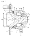
- Fig. 1 is a longitudinal section view showing a first embodiment of the bearing apparatus for a wheel of vehicle of the present invention
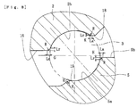
- Fig. 2 is an enlarged sectional view of the hub wheel of Fig. 1
- Fig. 3 is an enlarged sectional view of a condition during assembly of the inner side ball group onto the inner raceway surfaces of the hub wheel.
- a term "outer side" (left hand side in the drawings) of the apparatus denotes a side which is positioned outside of the vehicle body
- a term “inner side” (right hand side in the drawings) of the apparatus denotes a side which is positioned inside of the body when the bearing apparatus is mounted on the vehicle body.
- the bearing apparatus for a wheel of vehicle of the present invention shown in Fig. 1 is a third generation type used for a driven wheel and comprises an inner member 1, an outer member 2, and double rows of balls (ball groups) 3, 3 for rollably contained between the inner and outer members 1, 2.
- the inner member comprises the hub wheel 4 and an inner ring 5 press fitted on the hub wheel with a predetermined interference.
- the hub wheel 4 is integrally formed with a wheel mounting flange 6 at its one end, one (outer side) inner raceway surface 4a on the outer circumferential surface, and a cylindrical portion 4b extending from the inner raceway surface 4a through a shaft shaped portion 7.
- Hub bolts 6a are arranged on the wheel mounting flange 6 equidistantly along the periphery of the wheel mounting flange 6 and circular apertures 6b are formed between the hub bolts 6a. These circular apertures 6b contribute not only to reduction of the weight of the bearing apparatus but to passage of any fastening tool used for assembly and disassembly of the bearing apparatus.
- the inner ring 5 is formed on its outer circumferential surface with the other (inner side) inner raceway surface 5a and adapted to be press fitted on the cylindrical portion 4b of the hub wheel 4 with a predetermined interference and to be axially secured by a caulked portion 8 formed by plastically deforming the end of the cylindrical portion 4b.
- the hub wheel 4 is made of medium carbon steel including carbon of 0.40-80% by weight such as S53C and hardened by high frequency induction quenching so that a region including the inner raceway surface 4a from the inner side base 6c of the wheel mounting flange 6 to the cylindrical portion 4b has surface hardness of 58-64 HRC.
- the caulked portion 8 is remained as its surface hardness after forging. Accordingly the wheel mounting flange 6 has a sufficient mechanical strength against the rotary bending load applied thereto and the anti-fretting strength of the cylindrical portion 4b at a region press fitted by the inner ring 5 can be improved and the plastically deforming working of the caulked portion 8 can be also carried out without any micro crack during caulking process.
- the inner ring 5 and the balls 3 are made of high carbon chrome bearing such as SUJ 2 and hardened to their core by dipping quenching as having hardness of 58 ⁇ &4 HRC.
- the outer member 2 is integrally formed on its outer circumferential surface with a body mounting flange 2c to be mounted on a knuckle (not shown) of a vehicle and on its inner circumferential surface with an outer side outer raceway surface 2a opposite to the inner raceway surface 4a of the hub wheel 4 and an inner side outer raceway surface 2b opposite to the inner raceway surface 5a of the inner ring 5. Double rows of balls 3, 3 are contained between these outer and inner raceway surfaces and rollably held by cages 9, 10.
- the outer member 2 is made of medium carbon steel including carbon of 0.40 ⁇ 0.80% by weight such as S53C and the double row outer raceway surfaces 2a, 2b are hardened by high frequency induction quenching so as to have a surface hardness of 58-64 HRC.
- a seal 11 is mounted within an outer side end portion of an annular space formed between the outer member 2 and the inner member 1 and a magnetic encoder 12 is mounted within an inner side end of the annular space for detecting the rotational speed of wheel.
- the seal 11 and a cap (not shown) covering the opened end of the outer member 2 prevent leakage of grease contained in the bearing and entering of rain water and dusts into the bearing from outside.
- a pitch circle diameter PCDo of the outer side ball group 3 is set larger than a pitch circle diameter PCDi of the inner side ball group 3 (PCDo>PCDi).
- the diameter "d" of each ball 3 is same both in the outer side and inner side and thus the number of the ball group 3 in the outer side is larger than that of the ball group 3 in the inner side because of the fact PCDo>PCDi.
- a substantially conical recess 13 is formed at an outer side end portion of the hub wheel 4 in order to reduce the weight of the bearing apparatus and the depth of the recess 13 extends to near the bottom of the inner raceway surface 4a of the hub wheel 4 so that outer side end portion of the hub wheel 4 has a substantially constant wall thickness.
- the outline configuration of the hub wheel 4 is gradually reduced from the inner raceway surface 4a to the cylindrical portion 4b via the counter portion 14, a stepped portion 7a, the shaft shaped portion having a smaller diameter, and a shoulder portion 7b to which the inner ring 5 is abutted.
- the diameter of the inner raceway surface 4a of the hub wheel 4 is larger than that of the inner raceway surface 5a of the inner ring 5 and the outer diameter of the shaft shaped portion 7 is set so that it has substantially same diameter as the bottom diameter of the inner raceway surface 5a of the inner ring 5.
- the diameter of the outer side outer raceway surface 2a is larger than that of the inner side outer raceway surface 2b.
- the outer side outer raceway surface 2a continues to the inner side outer raceway surface 2b via a cylindrical shoulder 15, a stepped portion 15a and a shoulder 16 of a smaller diameter.
- the inner diameter of the bottom of the outer raceway surface 2b is set so that it has substantially same diameter as the inner diameter of the shoulder 15 of a larger diameter.
- the pitch circle diameter PCDo of the outer side ball group 3 is larger than the pitch circle diameter PCDi of the inner side ball group 3 and the number of the outer side ball group 3 is also larger than that of the inner side ball group 3, the rigidity of the bearing apparatus at the outer side can be increased and thus the life of the bearing apparatus can be extended.
- a recess 13 is formed at the outer side end portion of the hub wheel 4 so that the wall thickness of the hub wheel 4 at this outer side end portion is substantially constant. This enables to solve the antinomic problems of reducing the weight and size of the bearing apparatus and of increasing the rigidity of the bearing apparatus.
- a ratio of the diameter "d" of each ball 3 to the pitch circle diameter PCDi of the inner side ball group 3 (d/PCDi) is set in a predetermined range i.e. 0.14 ⁇ (d/PCDi) ⁇ 0.25.
- a smaller diameter "d" of each ball 3 is preferable since a larger number of balls 3 (i.e. a smaller diameter "d") can increase the bearing rigidity in a same pitch circle diameter PCDi.
- a larger diameter "d” of ball 3 is preferable since the larger diameter "d” of ball 3 reduces the rolling fatigue strength.
- each corner portion on the outer circumferential surface of the hub wheel 4 is rounded as having a smooth circular arc. That is, as shown in an enlarged view of Figs. 2 , a corner (transition) A between the base portion (shoulder) 6c and the inner raceway surface 4a, and a corner B of the stepped portion 7a are formed as having a predetermined chamfered configuration having a corner radius R.
- the corner A is formed so that it has the axial chamfer dimension La of 0.1.5 ⁇ 0.8 mm, preferably 0.15 ⁇ 0.3 mm, and the radial chamfer dimension Lr of 0.15 ⁇ 0.8 mm, preferably 0.15 ⁇ 0.3 mm, and the corner radius R of 0.15 ⁇ 2.0 R, preferably 0.45 ⁇ 0.7 R in order to have smooth transition portions.
- the corner radius R is less than 0.15 R balls 3 would tend to be scratched, on the other hand when the corner radius R exceeds 2.0 R the oval contact region of ball 3 (i.e. oval region formed by an contact area between the ball 3 and the inner raceway surface 4a) would tend to ride over the inner raceway surface 4a and come out from the inner raceway surface 4a.
- the corner B is formed so that it has the axial chamfer dimension La and the radial chamfer dimension Lr of 0.5 ⁇ 5 mm, and the corner radius R of 1.0 ⁇ 10 R and thus has a smooth transition portion.
- a counter portion 14 is formed near the bottom of the inner raceway surface 4a as having a predetermined width and a diameter larger than that of the bottom of the inner raceway surface 4a.
- the counter portion 14 comprises a corner portion C near the bottom of the inner raceway surface 4a, and a smaller diameter portion 14a formed by a circular arc surface having a predetermined radius of curvature.
- the stepped portion 7a is formed adjacent to the smaller diameter portion 14a via a corner B.
- the corner C of the counter portion 14 is also formed as a smooth circular arc having a corner radius R of 1.0 ⁇ 5 R.
- edge load herein means a large concentrated stress generated in the corners and often causes premature delamination of parts.
- the corners A, C are ground by the formed grinding wheel simultaneously with the inner raceway surface 4a after heat treatment thereof and the corner B of the stepped portion 7a is formed as a rounded circular arc e.g. by a bite.
- This enables to prevent generation of burrs and thus to form the outer diameter of the counter portion 14 with a high accuracy.
- not only the inner raceway surface 4a of the hub wheel 4 but the shoulder 5b of the inner raceway surface 5a of the inner ring 5, shoulders 15, 16 of the outer raceway surfaces 2a, 2b of the outer member 2 and their counter portions are rounded and formed as smooth circular arcs. This enables to prevent generation of ball damages during assembly of the bearing apparatus and to prevent generation of "edge load" even though the oval contacting region rides over the corners.
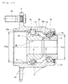
- Fig. 4 is a longitudinal section view showing a second embodiment of the bearing apparatus for a wheel of vehicle of the present invention
- Fig. 5 is an enlarged sectional view of the hub wheel of Fig. 4
- Fig. 6 is an enlarged sectional view of a condition during assembly of the inner side ball group onto the inner raceway surfaces of the hub wheel
- Fig. 7 is an enlarged sectional view of the bearing row of outer side of Fig. 4
- Fig. 8 is an enlarged sectional view of the bearing row of inner side of Fig. 4
- Fig. 9 is an explanatory view showing a grinding work applied to the outer member after heat treatment thereof
- FIG. 10 (a) is an explanatory view showing a grinding work applied to the hub wheel after heat treatment thereof
- Fig. 10 (b) is an explanatory view showing a grinding work applied to the inner ring after heat treatment thereof. Since the second embodiment is different from the first embodiment only in the structure of the hub wheel, same reference numerals are used herein for designating same parts as those having same functions used in the first embodiment.
- This bearing apparatus is a third generation type used for a driven wheel and comprises an inner member 20, an outer member 2, and double row ball groups 3, 3 freely rollably contained between the outer and inner members 20, 2.
- the inner member 20 comprises a hub wheel 21, and the inner ring 5 press fitted onto the hub wheel 21 via a predetermined interference.
- the hub wheel 21 is made of medium carbon steel including carbon of 0.40 ⁇ 0.80%by weight such as S53C and formed with a recess 22.
- the recess 22 is provided at the outer side end portion of the hub wheel 21 and is deeper than the recess 13 of the first embodiment (shown by a phantom line).
- the depth of recess 22 extends to a position near a stepped portion 24 beyond the bottom of the inner raceway surface 4a so that the wall thickness of the outer side end portion of the hub wheel 21 becomes substantially constant.
- the diameter of the inner raceway surface 4a of the hub wheel 21 is larger than that of the inner raceway surface 5a of the inner ring 5 and the outer diameter of the shaft shaped portion 23 is set so --that it has larger diameter than the bottom diameter of the inner raceway surface 5a of the inner ring 5.
- the bearing apparatus of the second embodiment has a large bearing rigidity at the outer side than at the inner side.
- the depth of the recess 22 in the second embodiment is larger than that of the recess 13 in the first embodiment, reduction of weight of the bearing apparatus can be further promoted.
- each of the corner portions on the outer circumferential surface of the hub wheel 21 is rounded as having a smooth circular arc. That is, as shown in an enlarged view of Figs. 5 , a corner (transition) A between the base portion 6c and the outer side inner raceway surface 4a, a corner D between the tapered stepped portion 24 and the shaft shaped portion 23, and a corner E between the stepped portion 24 and the shoulder 7b are formed as having a predetermined chamfered configuration having a corner radius R.
- each of the corners D, E is formed so that it has the axial chamfer dimension La of 0.5 ⁇ 5 mm and the radial chamfer dimension Lr of 0.5 ⁇ 5 mm, and the corner radius R of 1.0 ⁇ 10 R to have smooth transition portions.
- corner portions A, C, D, E on the outer circumferential surface of the hub wheel 21 are rounded, it is possible to suppress generation of damages on the balls 3 during assembling step of the bearing apparatus although the outer side balls 3 would contact the corners A, C, D, E of the hub wheel 21 and thus to improve the noise characteristics and the life of the bearing apparatus.
- each of the corner A between the raceway surface 4a and the base portion 6c, corners F, G at the shoulders 15, 16 of the outer member 2, and a corner H on the outer circumferential surface 5b of the inner ring 5 is rounded as having a smooth circular arc
- each of the counter portions 17, 18 of the outer member 2, corners J, K on the outer raceway surfaces 2a, 2b, and a corner M of a counter portion 19 is also rounded as having a smooth circular arc.
- the counter portions 17, 18, 14, 19 axially correspond to the shoulder portions 15, 16, 6c, 5b respectively of each raceway surface. More particularly as shown in enlarged views of Figs.
- the axial chamfer dimension La is 0.15 ⁇ 0.8 mm, preferably 0.15 ⁇ 0.3 mm
- the radial chamfer dimension Lr is 0.15 ⁇ 0.8 mm, preferably 0.15 ⁇ 0.3 mm
- the corner radius R is 0.15 ⁇ 2.0 R, preferably 0.45 ⁇ 0.7 R in order to have smooth transition portions.
- the corner portions A, F, G, H of shoulders and the corner portions C, J, K, M of the counter portions are ground simultaneously with the raceway surfaces after heat treatment by formed grinding wheels 25, 26, 27. That is, as shown in Fig. 9 , the double row outer raceway surfaces 2a, 2b of the outer member 2 are ground together by the formed grinding wheel 25 and the corners F, G of the shoulders 15, 16 and the corner portions J, K of the counter portions 17, 18 are also simultaneously ground by the formed grinding wheel 25. Also as shown in Fig.
- each ball 3 has different diameters.
- the diameter of each ball arranged at the outer side may be smaller than that of each ball arranged at the inner side to increase the number of ball in the outer side row.
- Fig. 11 is a longitudinal section view showing a third embodiment of the bearing apparatus for a wheel of vehicle of the present invention. Same reference numerals are used herein for designating same parts as those having same functions used in the previous embodiments.
- This bearing apparatus is a second generation type used for a driven wheel and comprises an inner member 28, an outer member 29, and double row balls 3, 3 freely rollably contained between the outer and inner members 28, 29.
- the inner member 28 comprises a pair of inner rings 30, 5 formed on their outer circumferential surfaces with inner raceway surfaces 30a, 5a.
- the outer member 29 is made of medium carbon steel including carbon of 0.40 ⁇ 0.80% by weight such as S53C and integrally formed on its outer circumferential surface with a wheel mounting flange 6 and on its inner circumferential surface with double row outer raceway surfaces 2a, 2b.
- the double row ball groups 3, 3 are rollably contained between the outer and inner raceway surfaces by cages 9, 10 and forms a back-to-back double row angular contact ball bearing.
- a seal 31 is mounted on the inner side end portion of the outer member 29 and a labyrinth seal 32 is formed between the outer side end and the inner ring 30. These seals 32 and a cap (not shown) covering the opened end of the outer member 29 prevent leakage of grease contained in the bearing and entering of rain water and dusts into the bearing from outside.
- a pitch circle diameter PCDo of the outer side ball group 3 is set larger than a pitch circle diameter PCDi of the inner side ball group 3.
- the diameter "d" of each ball 3 is same both in the outer side and inner side and thus the number of the ball group 3 in the outer side is larger than that of the ball group 3 in the inner side because of the fact PCDo>PCDi. Due to the fact PCDo>PCDi, the diameter of the outer raceway surface 30a of the outer side inner ring 30 is larger than that of the inner raceway surface 5a of the inner side inner ring 5.
- the bearing apparatus for a wheel of vehicle of the present invention can be applied to any of the bearing apparatus of the first-fourth generations irrespective for the driving wheel or the driven wheel.
Landscapes
- Engineering & Computer Science (AREA)
- General Engineering & Computer Science (AREA)
- Mechanical Engineering (AREA)
- Manufacturing & Machinery (AREA)
- Rolling Contact Bearings (AREA)
Claims (7)
- Dispositif de roulement à billes angulaire en double rangée pour une roue d'un véhicule comprenant un élément extérieur (2, 29) formé sur sa surface circonférentielle interne avec des surfaces de chemin de roulement externes (2a, 2b) en double rangée ; des éléments internes (1, 20, 28) formés chacun sur sa surface circonférentielle externe avec des surfaces de chemin de roulement internes en double rangée (4a, 5a, 30a) disposées à l'opposé des surfaces de chemin de roulement externes à double rangée (2a, 2b) ; et des groupes de billes en double rangée (3) roulant librement contenus entre les surfaces de chemins de roulement externes (2a, 2b) et les surfaces de chemins de roulement internes (4a, 5a, 30a) des éléments internes (1,20,28) et de l'élément externe (2, 30), dans lequel un diamètre de cercle primitif (PCDo) d'un groupe de billes (3) du côté externe est plus grand qu'un diamètre de cercle primitif (PCDi) d'un groupe de billes (3) du côté interne, caractérisé en ce que chacune des portions de coin (A, B, C, D, E, H, M) des surfaces circonférentielles externes de l'élément interne (1, 20, 28) est arrondie comme un arc circulaire lisse, en ce que chacune des portions de coin (C, J, K, M) des portions opposées (14, 17, 18, 19) des surfaces de chemin de roulement externe et interne est arrondie comme un arc circulaire lisse, et en ce que une portion opposée (14) est formée près de la base de la surface de chemin de roulement interne (4a) du moyeu de roue (4) et possède une largeur prédéterminée et un diamètre plus grand que celui de la base de ladite surface de chemin de roulement interne (4a).
- Dispositif de roulement à billes angulaire en double rangée pour une roue de véhicule selon la revendication 1, dans lequel chacune des portions de coin (A, F, G, H) des épaulements des surfaces de chemin de roulement externe et interne est arrondie comme un arc circulaire lisse.
- Dispositif de roulement à billes angulaire en double rangée pour une roue de véhicule selon les revendications 1 ou 2, dans lequel le diamètre externe de chaque bille (3) est identique, et le nombre de groupes de billes (3) du côté externe est plus grand que celui de groupes de billes (3) du côté interne.
- Dispositif de roulement à billes angulaire en double rangée pour une roue de véhicule selon une quelconque des revendications 1 à 3, dans lequel ledit élément interne (1, 20) comprend un moyeu de roue (4, 21) ayant une monture de roue (6) formée en un seul tenant avec celui-ci à une extrémité de celui-ci, une surface de chemin de roulement interne (4a) formée sur la surface circonférentielle externe de celui-ci opposée à une (2a) des surfaces de chemin de roulement externes en double rangée (2a, 2b), et une portion cylindrique (4b) s'étendant axialement à partir de la surface de chemin de roulement interne (4a), et comprend en outre un anneau interne (5) ajusté sur la portion cylindrique (4b) et formé sur sa surface circonférentielle externe avec l'autre surface de chemin de roulement interne (5a) opposée à l'autre surface de chemin de roulement (2b) des surfaces de chemin de roulement externes en double rangée (2a, 2b) ; et dans lequel un évidement substantiellement conique (13 ou 22) est formé sur une portion d'extrémité latérale externe du moyeu de roue (4), et le profondeur de l'évidement (13) s'étend au moins près de la base de la surface de chemin de roulement interne (4a) du moyeu de roue (4) de sorte que la portion d'extrémité latérale externe (4a) du moyeu de roue (4) ait une épaisseur de paroi substantiellement constante.
- Dispositif de roulement à billes angulaire en double rangée pour une roue de véhicule selon la revendication 4, dans lequel une portion en forme d'arbre (23) est formée de sorte qu'elle s'étend à partir de la base de la surface de chemin de roulement interne (4a) du moyeu de roue (21) vers la portion cylindrique (4b), et une portion étagée effilée (24) est formée entre la portion en forme d'arbre (23) et un épaulement (7b) sur lequel l'anneau interne (5) vient buter, et dans lequel la profondeur de l'évidement (22) s'étend vers la portion étagée (24) au-delà de la base de la surface de chemin de roulement interne (4a).
- Dispositif de roulement à billes angulaire en double rangée pour une roue de véhicule selon une quelconque des revendications 1 à 5, dans lequel un rapport (d/PCDi) du diamètre externe (d) de chaque bille (3) sur un diamètre de cercle primitif (PCDi) d'un groupe de billes (3) du côté interne est réglé dans une plage de 0.14 ≤ (d/PCDi) ≤ 0.25.
- Procédé de fabrication d'un dispositif de roulement à billes angulaire en double rangée pour une roue de véhicule selon une quelconque des revendications 1 à 6, dans lequel les portions de coin (A, B, D, E, F, G, H ; et C, J, K, M) respectivement des épaulements et des portions opposées sont ancrées simultanément dans les surfaces de chemins de roulement internes et externes après un traitement thermique par une meule à rectifier formée (25, 26, 27).
Applications Claiming Priority (3)
| Application Number | Priority Date | Filing Date | Title |
|---|---|---|---|
| JP2005312621A JP2007120594A (ja) | 2005-10-27 | 2005-10-27 | 車輪用軸受装置 |
| JP2005322324A JP2007127244A (ja) | 2005-11-07 | 2005-11-07 | 車輪用軸受装置 |
| PCT/JP2006/319854 WO2007049437A1 (fr) | 2005-10-27 | 2006-10-04 | Dispositif de palier pour roue |
Publications (3)
| Publication Number | Publication Date |
|---|---|
| EP1947355A1 EP1947355A1 (fr) | 2008-07-23 |
| EP1947355A4 EP1947355A4 (fr) | 2010-07-28 |
| EP1947355B1 true EP1947355B1 (fr) | 2013-11-27 |
Family
ID=37967555
Family Applications (1)
| Application Number | Title | Priority Date | Filing Date |
|---|---|---|---|
| EP06811194.7A Active EP1947355B1 (fr) | 2005-10-27 | 2006-10-04 | Dispositif de palier pour roue |
Country Status (3)
| Country | Link |
|---|---|
| US (1) | US7832941B2 (fr) |
| EP (1) | EP1947355B1 (fr) |
| WO (1) | WO2007049437A1 (fr) |
Families Citing this family (11)
| Publication number | Priority date | Publication date | Assignee | Title |
|---|---|---|---|---|
| CN101784397B (zh) * | 2007-10-02 | 2013-01-30 | 日本精工株式会社 | 滚动轴承单元用滚道环构件的制造方法 |
| JP2011002030A (ja) * | 2009-06-18 | 2011-01-06 | Ntn Corp | 車輪用軸受 |
| EP2503169B1 (fr) * | 2009-11-20 | 2019-01-09 | NSK Ltd. | Roulement à billes de type angulaire en tandem |
| JP5094897B2 (ja) * | 2010-03-08 | 2012-12-12 | 本田技研工業株式会社 | 電動遠心圧縮機 |
| IT1399978B1 (it) * | 2010-04-20 | 2013-05-09 | Skf Ab | Gruppo mozzo ruota a due corone di corpi volventi |
| JP5570297B2 (ja) | 2010-05-20 | 2014-08-13 | Ntn株式会社 | 車輪用軸受装置 |
| US8616779B2 (en) | 2010-11-29 | 2013-12-31 | Honda Motor Co., Ltd. | Shortened driveshaft stem |
| JP5720262B2 (ja) * | 2011-01-20 | 2015-05-20 | 株式会社ジェイテクト | 車輪用転がり軸受装置 |
| JP6009149B2 (ja) * | 2011-06-14 | 2016-10-19 | Ntn株式会社 | 車輪用軸受装置の製造方法 |
| JP5867685B2 (ja) * | 2011-09-16 | 2016-02-24 | Nok株式会社 | センターベアリングサポート |
| DE102016210882A1 (de) | 2015-06-19 | 2016-12-22 | Aktiebolaget Skf | Wälzlager, im Besonderen für eine Fahrzeuglenkanlage oder für eine Fahrzeugradnabengruppe |
Family Cites Families (30)
| Publication number | Priority date | Publication date | Assignee | Title |
|---|---|---|---|---|
| GB2123723A (en) * | 1982-01-19 | 1984-02-08 | Ntn Toyo Bearing Co Ltd | Method of manufacturing bearing unit for automobile wheel |
| US4454640A (en) * | 1982-09-13 | 1984-06-19 | Ntn Toyo Bearing Co., Ltd. | Method of producing bearing devices for driving wheels of automobiles |
| DE3608346A1 (de) * | 1986-03-13 | 1987-09-17 | Kugelfischer G Schaefer & Co | Verfahren zum verbinden der teile einer radlagerung |
| JPS63166601A (ja) * | 1986-12-27 | 1988-07-09 | Koyo Seiko Co Ltd | 自動車のホイ−ル用軸受ユニツト |
| JP2620689B2 (ja) * | 1987-06-02 | 1997-06-18 | 光洋精工株式会社 | 円錐ころ軸受内輪の加工方法 |
| US5195807A (en) * | 1992-04-20 | 1993-03-23 | General Motors Corporation | Venting wheel bearing end cap |
| JP3690821B2 (ja) * | 1993-12-15 | 2005-08-31 | 日本精工株式会社 | 車輪用複列アンギュラ型玉軸受 |
| DE19602407C1 (de) * | 1996-01-24 | 1997-08-21 | Gkn Automotive Ag | Baueinheit zum Antrieb und zur Lagerung eines Rades eines Kraftfahrzeuges |
| DE19613441B4 (de) * | 1996-04-04 | 2005-03-24 | Fag Kugelfischer Ag | Verfahren zur Herstellung einer aus mehreren Einzelteilen bestehenden Wälzlagerbaueinheit |
| JP3845942B2 (ja) * | 1997-03-31 | 2006-11-15 | 日本精工株式会社 | 車輪支持用ハブユニット |
| JPH1162985A (ja) * | 1997-08-26 | 1999-03-05 | Nippon Seiko Kk | 転がり玉軸受 |
| DE19882672B4 (de) * | 1997-09-10 | 2006-11-02 | Gkn Driveline International Gmbh | Sicheres Verbinden von Bauteilen mittels Federringen |
| JP3766946B2 (ja) * | 1998-08-31 | 2006-04-19 | 株式会社ジェイテクト | ホィール用軸受装置 |
| JP2000110839A (ja) * | 1998-10-01 | 2000-04-18 | Nsk Ltd | 複列玉軸受 |
| JP4019548B2 (ja) * | 1999-04-05 | 2007-12-12 | 日本精工株式会社 | 車輪支持用転がり軸受ユニットとその製造方法 |
| JP4262851B2 (ja) * | 2000-01-11 | 2009-05-13 | Ntn株式会社 | 車輪軸受装置 |
| EP1190870B1 (fr) * | 2000-09-20 | 2010-03-03 | Ntn Corporation | Dispositif de palier de roue |
| DE10219018B8 (de) * | 2002-04-27 | 2004-10-28 | Gkn Driveline International Gmbh | Radnabeneinheit |
| JP4251314B2 (ja) * | 2002-07-16 | 2009-04-08 | Ntn株式会社 | 車輪用軸受装置 |
| WO2004022992A1 (fr) * | 2002-09-06 | 2004-03-18 | Nsk Ltd. | Unite de roulement conçue pour soutenir une roue |
| JP2004100754A (ja) * | 2002-09-06 | 2004-04-02 | Nsk Ltd | 軸受装置の外輪内面の滑面仕上処理方法および該処理方法を施した軸受装置 |
| JP4206716B2 (ja) * | 2002-09-17 | 2009-01-14 | 株式会社ジェイテクト | 転がり軸受装置 |
| DE602004026367D1 (de) * | 2003-04-17 | 2010-05-12 | Ntn Toyo Bearing Co Ltd | Lagerung für ein Kraftfahrzeugrad |
| US7093703B2 (en) * | 2003-04-23 | 2006-08-22 | Koyo Seiko Co., Ltd. | One-way clutch integrated with a rolling bearing, and method of producing the same |
| JP2005061616A (ja) * | 2003-07-25 | 2005-03-10 | Ntn Corp | 車輪用軸受装置 |
| BRPI0415473B1 (pt) * | 2003-10-14 | 2015-12-01 | Skf Ab | conjunto de mancal de cubo |
| JP4471150B2 (ja) * | 2003-11-05 | 2010-06-02 | Ntn株式会社 | 車輪用軸受装置およびその製造方法 |
| JP2005306157A (ja) * | 2004-04-20 | 2005-11-04 | Nsk Ltd | 車輪支持用転がり軸受ユニット及びその製造方法 |
| JP2005324714A (ja) * | 2004-05-17 | 2005-11-24 | Ntn Corp | 車輪用軸受装置 |
| JP3923986B2 (ja) * | 2005-05-10 | 2007-06-06 | Ntn株式会社 | 車輪用軸受装置 |
-
2006
- 2006-10-04 WO PCT/JP2006/319854 patent/WO2007049437A1/fr active Application Filing
- 2006-10-04 EP EP06811194.7A patent/EP1947355B1/fr active Active
-
2008
- 2008-04-22 US US12/107,144 patent/US7832941B2/en active Active
Non-Patent Citations (1)
| Title |
|---|
| SKF: "SKF Explorer Angular Contact BAll Bearings", 1 January 2003 (2003-01-01), Retrieved from the Internet <URL:http://www.skf.com/files/239445.pdf> [retrieved on 20110405] * |
Also Published As
| Publication number | Publication date |
|---|---|
| WO2007049437A1 (fr) | 2007-05-03 |
| US7832941B2 (en) | 2010-11-16 |
| EP1947355A1 (fr) | 2008-07-23 |
| EP1947355A4 (fr) | 2010-07-28 |
| US20080205811A1 (en) | 2008-08-28 |
Similar Documents
| Publication | Publication Date | Title |
|---|---|---|
| EP1947355B1 (fr) | Dispositif de palier pour roue | |
| EP1944518B1 (fr) | Dispositif a palier pour roue | |
| US8631581B2 (en) | Method for forming a wheel bearing apparatus | |
| US7862242B2 (en) | Wheel bearing apparatus for a vehicle | |
| US7748909B2 (en) | Bearing apparatus for a wheel of vehicle | |
| US7832942B2 (en) | Wheel bearing apparatus | |
| EP1939471B1 (fr) | Dispositif de roulement pour roue | |
| US8267593B2 (en) | Bearing apparatus for a wheel of vehicle | |
| US7942585B2 (en) | Wheel bearing apparatus for a vehicle | |
| US7641394B2 (en) | Bearing apparatus for a wheel of vehicle | |
| US8308371B2 (en) | Bearing apparatus for a wheel of vehicle | |
| JP2007100715A (ja) | 車輪用軸受装置 | |
| JP2007147064A (ja) | 車輪用軸受装置 | |
| JP2008051164A (ja) | 車輪用軸受装置 | |
| JP5024850B2 (ja) | 車輪用軸受装置 | |
| JP4998980B2 (ja) | 車輪用軸受装置 | |
| JP2008051165A (ja) | 車輪用軸受装置 | |
| JP2007120594A (ja) | 車輪用軸受装置 | |
| JP4969899B2 (ja) | 車輪用軸受装置 | |
| JP2007298159A (ja) | 車輪用軸受装置 | |
| JP4034799B2 (ja) | 車輪用軸受装置 | |
| JP4986277B2 (ja) | 車輪用軸受装置 | |
| JP2007113719A (ja) | 車輪用軸受装置 | |
| JP2007127244A (ja) | 車輪用軸受装置 |
Legal Events
| Date | Code | Title | Description |
|---|---|---|---|
| PUAI | Public reference made under article 153(3) epc to a published international application that has entered the european phase |
Free format text: ORIGINAL CODE: 0009012 |
|
| 17P | Request for examination filed |
Effective date: 20080527 |
|
| AK | Designated contracting states |
Kind code of ref document: A1 Designated state(s): DE FR |
|
| DAX | Request for extension of the european patent (deleted) | ||
| RBV | Designated contracting states (corrected) |
Designated state(s): DE FR |
|
| A4 | Supplementary search report drawn up and despatched |
Effective date: 20100624 |
|
| RIC1 | Information provided on ipc code assigned before grant |
Ipc: F16C 43/06 20060101ALI20100618BHEP Ipc: F16C 19/18 20060101ALI20100618BHEP Ipc: F16C 33/58 20060101AFI20070622BHEP Ipc: B60B 35/18 20060101ALI20100618BHEP |
|
| 17Q | First examination report despatched |
Effective date: 20110413 |
|
| GRAP | Despatch of communication of intention to grant a patent |
Free format text: ORIGINAL CODE: EPIDOSNIGR1 |
|
| INTG | Intention to grant announced |
Effective date: 20130628 |
|
| GRAS | Grant fee paid |
Free format text: ORIGINAL CODE: EPIDOSNIGR3 |
|
| GRAA | (expected) grant |
Free format text: ORIGINAL CODE: 0009210 |
|
| AK | Designated contracting states |
Kind code of ref document: B1 Designated state(s): DE FR |
|
| REG | Reference to a national code |
Ref country code: DE Ref legal event code: R096 Ref document number: 602006039449 Country of ref document: DE Effective date: 20140116 |
|
| REG | Reference to a national code |
Ref country code: DE Ref legal event code: R097 Ref document number: 602006039449 Country of ref document: DE |
|
| PLBE | No opposition filed within time limit |
Free format text: ORIGINAL CODE: 0009261 |
|
| STAA | Information on the status of an ep patent application or granted ep patent |
Free format text: STATUS: NO OPPOSITION FILED WITHIN TIME LIMIT |
|
| 26N | No opposition filed |
Effective date: 20140828 |
|
| REG | Reference to a national code |
Ref country code: DE Ref legal event code: R097 Ref document number: 602006039449 Country of ref document: DE Effective date: 20140828 |
|
| REG | Reference to a national code |
Ref country code: FR Ref legal event code: PLFP Year of fee payment: 11 |
|
| REG | Reference to a national code |
Ref country code: FR Ref legal event code: PLFP Year of fee payment: 12 |
|
| REG | Reference to a national code |
Ref country code: FR Ref legal event code: PLFP Year of fee payment: 13 |
|
| PGFP | Annual fee paid to national office [announced via postgrant information from national office to epo] |
Ref country code: FR Payment date: 20230911 Year of fee payment: 18 |
|
| PGFP | Annual fee paid to national office [announced via postgrant information from national office to epo] |
Ref country code: DE Payment date: 20230830 Year of fee payment: 18 |