EP1947285A2 - Rollladen - Google Patents
Rollladen Download PDFInfo
- Publication number
- EP1947285A2 EP1947285A2 EP08100063A EP08100063A EP1947285A2 EP 1947285 A2 EP1947285 A2 EP 1947285A2 EP 08100063 A EP08100063 A EP 08100063A EP 08100063 A EP08100063 A EP 08100063A EP 1947285 A2 EP1947285 A2 EP 1947285A2
- Authority
- EP
- European Patent Office
- Prior art keywords
- roller shutter
- shutter according
- bore
- lamellae
- rope
- Prior art date
- Legal status (The legal status is an assumption and is not a legal conclusion. Google has not performed a legal analysis and makes no representation as to the accuracy of the status listed.)
- Granted
Links
Images




Classifications
-
- E—FIXED CONSTRUCTIONS
- E06—DOORS, WINDOWS, SHUTTERS, OR ROLLER BLINDS IN GENERAL; LADDERS
- E06B—FIXED OR MOVABLE CLOSURES FOR OPENINGS IN BUILDINGS, VEHICLES, FENCES OR LIKE ENCLOSURES IN GENERAL, e.g. DOORS, WINDOWS, BLINDS, GATES
- E06B9/00—Screening or protective devices for wall or similar openings, with or without operating or securing mechanisms; Closures of similar construction
- E06B9/02—Shutters, movable grilles, or other safety closing devices, e.g. against burglary
- E06B9/08—Roll-type closures
- E06B9/11—Roller shutters
- E06B9/15—Roller shutters with closing members formed of slats or the like
-
- E—FIXED CONSTRUCTIONS
- E06—DOORS, WINDOWS, SHUTTERS, OR ROLLER BLINDS IN GENERAL; LADDERS
- E06B—FIXED OR MOVABLE CLOSURES FOR OPENINGS IN BUILDINGS, VEHICLES, FENCES OR LIKE ENCLOSURES IN GENERAL, e.g. DOORS, WINDOWS, BLINDS, GATES
- E06B9/00—Screening or protective devices for wall or similar openings, with or without operating or securing mechanisms; Closures of similar construction
- E06B9/24—Screens or other constructions affording protection against light, especially against sunshine; Similar screens for privacy or appearance; Slat blinds
- E06B9/26—Lamellar or like blinds, e.g. venetian blinds
- E06B9/38—Other details
- E06B9/384—Details of interconnection or interaction of tapes and lamellae
-
- E—FIXED CONSTRUCTIONS
- E06—DOORS, WINDOWS, SHUTTERS, OR ROLLER BLINDS IN GENERAL; LADDERS
- E06B—FIXED OR MOVABLE CLOSURES FOR OPENINGS IN BUILDINGS, VEHICLES, FENCES OR LIKE ENCLOSURES IN GENERAL, e.g. DOORS, WINDOWS, BLINDS, GATES
- E06B9/00—Screening or protective devices for wall or similar openings, with or without operating or securing mechanisms; Closures of similar construction
- E06B9/02—Shutters, movable grilles, or other safety closing devices, e.g. against burglary
- E06B9/08—Roll-type closures
- E06B9/11—Roller shutters
- E06B9/15—Roller shutters with closing members formed of slats or the like
- E06B2009/1533—Slat connections
-
- E—FIXED CONSTRUCTIONS
- E06—DOORS, WINDOWS, SHUTTERS, OR ROLLER BLINDS IN GENERAL; LADDERS
- E06B—FIXED OR MOVABLE CLOSURES FOR OPENINGS IN BUILDINGS, VEHICLES, FENCES OR LIKE ENCLOSURES IN GENERAL, e.g. DOORS, WINDOWS, BLINDS, GATES
- E06B9/00—Screening or protective devices for wall or similar openings, with or without operating or securing mechanisms; Closures of similar construction
- E06B9/02—Shutters, movable grilles, or other safety closing devices, e.g. against burglary
- E06B9/08—Roll-type closures
- E06B9/11—Roller shutters
- E06B9/15—Roller shutters with closing members formed of slats or the like
- E06B2009/1533—Slat connections
- E06B2009/155—Slats connected by separate elements
- E06B2009/1555—Flexible elements, e.g. tapes, strips, cords or chains
Definitions
- the present invention relates to a roller shutter, in particular for mounting on a building opening, with a plurality of mutually coupled slats, which are preferably movable from a wound position to a planar position in front of a building opening.
- a roller shutter which has a plurality of fins, which have at its upper edge a hook element and on its underside a counter hook.
- the hook is formed from a web on which a plurality of openings are recessed sin. If the slats hang loosely together, the openings are in the visible range and thus allow a light incidence. Above a building opening, the slats can be wound on a roll, being rotatable in the region of the hook and the counter hook. When unwinding, the slats are pulled apart by their own weight and a building opening is partially shadowed by the roller shutter, then completely translucent.
- the slats are initially placed in the lower area, up to the top of the building opening on each other, until the building opening is shaded opaque.
- the lamellae which are formed as tubular elements, penetrated by holes through which a wire rope is pulled.
- a sleeve is pulled over the wire rope in each case between two slats.
- the slats are connected to a rigid wire, but hinders the winding.
- tubular elements used are relatively unstable and bend easily.
- the invention has the object to provide a roller shutter, in which the individual slats are interconnected by means of at least one flexible cable and held on the rope at a defined distance from each other, without affecting the appearance of the rope is affected.
- the invention solves this problem by the subject matter of claim 1. It provides a roller shutter, in particular for mounting on a building opening, with a plurality of mutually coupled fins, each having at least one bore, which of a flexible cable, in particular a wire rope, are interspersed, on which they are kept relatively spaced apart, without a holding device is arranged and visible on the rope in the area between the slats.
- the area of the rope between the slats is holding element-free.
- the optics is thus no longer adversely affected by a holding element in this area but remains filigree and appealing.
- the slats of solid material profiles in particular of light metal, where they are penetrated by the holes and held by means of material embossing on the rope.
- This variant of the invention does not require a separate retaining element on the rope and is therefore inexpensive and easy to produce. It also offers the required advantage of the appealing look without holding element between the slats.
- a holding element may be arranged within the bore on the rope, which is then to be designed in such a way that does not protrude to the outside and thus is not visible to a viewer when looking at the roller shutter from the side.
- FIG. 1 a building opening 1 extending over two floors is shown, which is divided into a plurality of surface elements, and can be shaded by blinds 2 according to the invention, the blinds 2 having a multiplicity of lamellae 3.
- the blinds form such wide and narrow translucent surfaces 4, 5.
- the individual lamellae 3 are connected via at least one or more cables 10 (FIG. Fig. 4 ), in particular wire cables, connected to each other. Preferably, they can be rolled up by pulling on traction devices (not shown here in detail).
- the lamellae 3 preferably have - but not necessarily - a cross section according to the type Fig. 2 on.
- Fig. 2 shows the state of the preferred orientation when the slats 3 are used for shading a vertical surface.
- the use of the slats 3 is of course not limited to this geometry of the slats and the selected orientation. The illustrated geometry is particularly advantageous.
- the lamellae 3 are preferably made of a light metal such as aluminum and are particularly preferably designed as solid, non-hollow (extruded) profiles.
- the individual lamellae 3 in cross-section preferably only an extension of a few millimeters (5 to 10 mm), so that they remain lightweight despite training as solid profiles and yet are particularly stable, so that they have significant advantages over hollow sections form similar low cross-section, which usually bend relatively easily.
- the lamellas 3 form in cross-section almost a kind of right-angled triangle, the triangle to be considered in section forming a base 6, one here Almost at right angles aligned side surface 8 - but preferably bent in a concave shape - and has an inclined surface 7.
- the edge regions between the surfaces 6, 7, 8 are preferably provided with relatively large radii and thus formed rounded.
- the lamellae 3 - depending on the number of connecting ropes 10 - at least once or repeatedly penetrated by holes 9, which preferably extend between the base 6 and the inclined surface 7. Since the side surface 8 to the bore 9 "concave inward" is formed, the distance between the bore 9 and the side surface 8 in the central region of the side surface 8 is the smallest.
- the concave design also provides an optical advantage in that light is refracted and thus the surfaces appear evenly with soft contrast.
- the bore 9 to the base 12 toward a larger diameter than the inclined surface 7 out can be realized, for example, in that the bore 9 is stepped towards the base 6, so that a lower bore region 12 is formed, which forms a blind hole-like collar 17.
- a short retaining element 13 e.g. a compressed and fixed to the wire 10 sleeve, provided, which is designed such that it is completely accommodated in the bore region 12, without protruding outwardly from the bore.
- the sleeve 13 may be fixed by clamping on the cable 10.
- the holding element may be clamped in the bore, so that the lamellae 3 are held vertically in both directions.
- a holding element such as a sleeve 13 is again required to space the lamellae 3 defined on the wire rope from each other.
- the holding element 13 is not visible to the viewer from the side, so that the filigree appearance of a wire rope connection is not hindered. Not even an embossment is visible, so that the visual impression is particularly advantageous here.
- Fig. 7 illustrates that according to the invention it is also possible in a simple manner to choose the distance of the slats 3 within a roller shutter 3 different.
- the distance 14 between two lamellae 3 in the manner of Fig. A, b, c be different in size, for example, to meet the special requirements in a room where, for example, in different room heights light or sun rays 15 from different angles of incidence ( Angle of incidence 16) should be prevented from direct light.
Landscapes
- Engineering & Computer Science (AREA)
- Structural Engineering (AREA)
- Architecture (AREA)
- Civil Engineering (AREA)
- Operating, Guiding And Securing Of Roll- Type Closing Members (AREA)
- Blinds (AREA)
Abstract
Description
- Die vorliegende Erfindung betrifft einen Rollladen, insbesondere zur Montage an einer Gebäudeöffnung, mit einer Vielzahl von miteinander gekoppelten Lamellen, die vorzugsweise von einer aufgewickelten Position in eine flächige Position vor einer Gebäudeöffnung bewegbar sind.
- Aus der
FR 1 519 724 - Dann werden die Lamellen anfangs im unteren Bereich, bis hin zur Oberkante der Gebäudeöffnung aufeinander gelegt, bis die Gebäudeöffnung opak verschattet ist.
- Aufgegriffen wurde diese Lösung wieder in der
DE 101 39 583 A1 ,Fig. 4 . AusFig. 3 und4 dieser Schrift ist ein Rollladen bekannt, der eine Vielzahl von Lamellen aufweist, die mittels Hakenelementen miteinander verbunden sind, welche die Lamellen durchsetzen. Dadurch können die Lamellen wiederum lose aneinander gehängt werden, wobei eine vertikale Bewegbarkeit der Lamellen untereinander durch die offene Gestaltung des Hakens und des Gegenhakens erhalten bleibt. Die Montage ist zudem problematisch. - Nach einer weiteren Lösung dieser Schrift sind die Lamellen, die als rohrförmige Elemente ausgebildet sind, von Bohrungen durchsetzt, durch welche ein Drahtseil gezogen ist. Um die Lamellen relativ zueinander auf Abstand zu halten, ist jeweils zwischen zwei Lamellen eine Hülse über das Drahtseil gezogen. Hieran ist nachteilig, dass die Hülsen die Optik der Anordnung nachteilig beeinflussen. Die an sich durch Einsatz eines Seiles, insbesondere eines Drahtseiles, mögliche filigrane Optik geht derart verloren.
- Nach einer dritten Variante (Figuren 9 und 10) sind die Lamellen mit einem starren Draht verbunden, der aber das Aufwickeln behindert.
- Darüber hinaus sind die eingesetzten rohrförmigen Elemente relativ labil und knicken leicht.
- Die Erfindung hat die Aufgabe, einen Rollladen zu schaffen, bei dem die einzelnen Lamellen mittels wenigstens eines flexiblen Seils miteinander verbunden und auf dem Seil in definiertem Abstand zueinander gehalten sind, ohne dass hierdurch die Optik des Seiles beeinträchtigt wird.
- Die Erfindung löst diese Aufgabe durch den Gegenstand des Anspruchs 1. Sie schafft einen Rollladen, insbesondere zur Montage an einer Gebäudeöffnung, mit einer Vielzahl von miteinander gekoppelten Lamellen, die jeweils wenigstens eine Bohrung aufweisen, welche von einem flexiblen Seil, insbesondere einem Drahtseil, durchsetzt sind, auf dem sie relativ zueinander beabstandet gehalten sind, ohne dass auf dem Seil in dem Bereich zwischen den Lamellen eine Halteeinrichtung angeordnet und sichtbar ist.
- Damit ist der Bereich des Seiles zwischen den Lamellen halteelementfrei. Die Optik wird damit in diesem Bereich nicht mehr nachteilig von einem Halteelement beeinträchtig sondern bleibt filigran und ansprechend.
- Vorzugsweise bestehen die Lamellen aus Vollmaterialprofilen, insbesondere aus Leichtmetall, wobei sie von den Bohrungen durchsetzt und mittels Materialprägung auf dem Seil gehalten sind.
- Diese Variante der Erfindung kommt ohne separates Halteelement auf dem Seil aus und ist damit kostengünstig und leicht herstellbar. Sie bietet zudem den geforderten Vorteil der ansprechenden Optik ohne Halteelement zwischen den Lamellen.
- Alternativ kann ein Halteelement innerhalb der Bohrung auf dem Seil angeordnet sein, welches dann aber derart auszugestalten ist, dass nach außen nicht vorstehet und mithin von einem Betrachter nicht sichtbar ist, wenn der den Rollladen von der Seite betrachtet.
- Vorteilhafte Ausgestaltungen sind den Unteransprüchen zu entnehmen.
- Nachfolgend wird die Erfindung anhand eines Ausführungsbeispieles unter Bezug auf die Zeichnung näher erläutert. Es zeigen:
- Fig. 1
- eine Draufsicht auf eine Gebäudeöffnung mit mehreren Rolläden;
- Fig. 2
- einen Schnitt durch eine Lamelle eines Rollladens;
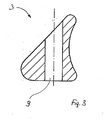
- Fig. 3
- einen Schnitt durch die Lamelle aus
Fig. 2 im Bereich einer Bohrung durch die Lamelle; - Fig. 4
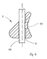
- den Schnitt durch die Lamelle aus
Fig. 3 mit einem Drahtseil, das die Bohrung durch die Lamelle durchsetzt; - Fig. 5, 6
- eine weitere Lamelle mit Bohrung, einmal mit und einmal ohne die Lamelle durchsetzendes Drahtseil;
- Fig. 7
- eine Darstellung von Lamellen eines Rollladens in verschiedenem Abstand zueinander.
- In
Figur 1 ist eine sich über zwei Etagen erstreckende Gebäudeöffnung 1 gezeigt, die in mehrere Flächenelemente aufgeteilt ist, und durch erfindungsgemäße Rolläden 2 verschattet werden können, wobei die Rolläden 2 eine Vielzahl von Lamellen 3 aufweisen. Die Rolläden bilden derart weite und enge transluzente Flächen 4, 5 aus. - Die einzelnen Lamellen 3 sind über wenigstens eines oder mehrere Seile 10 (
Fig. 4 ), insbesondere Drahtseile, miteinander verbunden. Vorzugsweise können sie durch Zug an Zugeinrichtungen (hier nicht im Detail dargestellt) aufgerollt werden. - Die Lamellen 3 weisen vorzugsweise - aber nicht zwingend - einen Querschnitt nach Art der
Fig. 2 auf. -
Fig. 2 zeigt quasi den Zustand der bevorzugten Ausrichtung, wenn die Lamellen 3 zur Beschattung einer vertikalen Fläche eingesetzt werden. Der Einsatz der Lamellen 3 ist selbstverständlich nicht auf diese Geometrie der Lamellen und die gewählte Ausrichtung beschränkt. Die dargestellte Geometrie ist aber besonders vorteilhaft. - Die Lamellen 3 bestehen vorzugsweise aus einem Leichtmetall wie Aluminium und sind besonders bevorzugt als massive, nicht hohle (Strangpreß-)Profile ausgebildet.
- Dies ist insbesondere möglich, da die einzelnen Lamellen 3 im Querschnitt vorzugsweise nur eine Erstreckung von wenigen Millimetern (5 bis 10 mm) aufweisen, so dass sie trotz der Ausbildung als Massivprofile leicht bleiben und dennoch besonders stabil sind, so dass sie deutliche Vorteile gegenüber Hohlprofilen ähnlich geringen Querschnitts bilden, die in der Regel relativ leicht knicken.
- Nach
Fig. 2 bilden die Lamellen 3 im Querschnitt nahezu eine Art rechtwinkliges Dreieck aus, wobei das im Schnitt zu betrachtende Dreieck eine Basis 6, eine hier nahezu rechtwinklig ausgerichtete Seitenfläche 8 - die aber vorzugsweise in sich konkav gebogen ausgebildet ist - und eine Schrägfläche 7 aufweist. Die Kantenbereiche zwischen den Flächen 6, 7, 8 sind vorzugsweise mit relativ großen Radien versehen und damit abgerundet ausgebildet. - Wie in
Fig. 3 zu erkennen, sind die Lamellen 3 - je nach Anzahl der sie verbindenden Seile 10 - wenigstens einmal oder mehrfach von Bohrungen 9 durchsetzt, die sich vorzugsweise zwischen der Basis 6 und der Schrägfläche 7 erstrecken. Da die Seitenfläche 8 zur Bohrung 9 "nach innen hin" konkav ausgebildet ist, ist der Abstand zwischen der Bohrung 9 und der Seitenfläche 8 im mittleren Bereich der Seitenfläche 8 am kleinsten. Die konkave Ausgestaltet bietet auch einen optischen Vorteil, da Licht gebrochen wird und damit die Oberflächen gleichmäßig mit weichem Kontrast erscheinen. - Diese Ausgestaltung ermöglicht es, die Lamellen 3 auf überraschend einfache Weise an Seilen, insbesondere Drahtseilen 10 (
Fig. 4 ), welche die Bohrungen 9 durchsetzen beabstandet zueinander festzulegen, indem einfach vorzugsweise im mittleren Bereich der Seitenfläche 8 mit konkaver Kontur eine Prägung 11 eingebracht wird, welche Material aus der Seitenfläche 8 der Lamelle gegen das Seil 10 drückt. Derart ist die Lamelle 3 in einfacher Weise ohne zusätzliches Hilfsmittel auf dem Seil 10 gehalten, ohne dass die Optik des Seils 10 beeinträchtigt wird. Die Kosten der Herstellung sind zudem minimal, da keine zusätzlichen Mittel zur Fixierung vorzusehen sind. - Es empfiehlt sich der Einsatz eines aus mehreren Einzelteilen geschlagenen Stahlseils, da hier die Prägung aufgrund der hohen Haftreibung besonders sicher hält.
- Eine alternative Ausgestaltung der Erfindung offenbart
Fig. 5 . - Danach weist die Bohrung 9 zur Basis 12 hin einen größeren Durchmesser auf als zur Schrägfläche 7 hin. Dies kann beispielsweise dadurch realisiert werden, dass die Bohrung 9 zur Basis 6 hin gestuft ausgebildet ist, so dass ein unterer Bohrungsbereich 12 ausgebildet wird, der einen sacklochartigen Kragen 17 ausbildet.
- Um die Lamelle 3 auf dem Drahtseil 10 an einem definierten Ort zu halten, wird dieses mit einem kurzen Haltelement 13, z.B. einer zusammengepressten und auf dem Drahtseil 10 festgelegten Hülse, versehen, die derart ausgestaltet ist, dass sie vollständig im Bohrungsbereich 12 unterbringbar ist, ohne dass sie nach außen aus der Bohrung vorsteht. Damit ist die Hülse 13 von außen für den Betrachter im Wesentlichen nicht sichtbar. Die Hülse 13 kann klemmend auf dem Seil 10 festgelegt sein. Das Haltelement kann klemmend in der Bohrung festgelegt sein, so dass die Lamellen 3 vertikal in beide Richtungen gehalten sind.
- Derart wird zwar wiederum ein Halteelement wie eine Hülse 13 dazu benötigt, um die Lamellen 3 auf dem Drahtseil definiert voneinander zu beabstanden.
- Von außen ist das Halteelement 13 aber für den Bertachter von der Seite aus nicht sichtbar, so dass die filigrane Optik einer Drahtseilverbindung nicht behindert wird. Nicht einmal eine Prägung ist sichtbar, so dass der optische Eindruck hier besonders vorteilhaft ist.
-
Fig. 7 veranschaulicht, dass es erfindungsgemäß auch auf einfache Weise möglich ist, den Abstand der Lamellen 3 innerhalb eines Rollladens 3 verschieden zu wählen. So kann der Abstand 14 zwischen zwei Lamellen 3 nach Art der Fig. a, b, c verschieden groß sein, um z.B. den besonderen Anforderungen in einem Raum gerecht zu werden, wo z.B. in verschiedenen Raumhöhen Licht- bzw. Sonnenstrahlen 15 aus verschiedenen Einfallswinkelbereichen (Einfallswinkel 16) am direkten Lichteinfall gehindert werden soll. -
- Gebäudeöffnung
- 1
- Rolläden
- 2
- Lamellen
- 3
- Flächen
- 4, 5
- Basis
- 6
- Schrägfläche
- 7
- Seitenfläche
- 8
- Bohrungen
- 9
- Seil
- 10
- Prägung
- 11
- Bohrungsbereich
- 12
- Haltelement
- 13
- Lamellenabstand
- 14
- Sonnenstrahlen
- 15
- Einfallswinkel
- 16
- Kragen
- 17
Claims (16)
- Rollladen, insbesondere zur Montage an einer Gebäudeöffnung (1), mit einer Vielzahl von miteinander gekoppelten Lamellen (3), die jeweils wenigstens eine Bohrung (9) aufweisen, welche von einem flexiblen Seil (10), insbesondere einem Drahtseil (10), durchsetzt ist, auf dem die Lamellen (3) relativ zueinander beabstandet gehalten sind, dadurch gekennzeichnet dass, die Lamellen (3) derart auf dem Seil (10) gehalten sind, dass auf dem Seil (10) in dem Bereich zwischen den Lamellen (3) kein Halteelement (10) sichtbar und angeordnet ist.
- Rollladen nach Anspruch 1, dadurch gekennzeichnet, dass die Lamellen (3) aus Vollmaterialprofilen bestehen.
- Rollladen nach Anspruch 1 oder 2, dadurch gekennzeichnet, dass die Lamellen (3) mittels einer Prägung im Bereich der Bohrung (9) auf dem Seil (10) festgelegt sind, mit der Material der Lamelle (3) gegen das Seil (10) gepresst ist.
- Rollladen nach einem der vorstehenden Ansprüche, dadurch gekennzeichnet, dass die Lamellen (3) im Querschnitt eine Dreiecksform ausbilden, wobei das im Schnitt zu betrachtende Dreieck eine Basis (6), eine hierzu ganz oder nahezu rechtwinklig ausgerichtete Seitenfläche (8) und eine Schrägfläche (7) aufweist.
- Rollladen nach einem der vorstehenden Ansprüche, dadurch gekennzeichnet, dass die Seitenfläche (8) in sich konkav gebogen ausgebildet ist.
- Rollladen nach einem der vorstehenden Ansprüche, dadurch gekennzeichnet, dass sich die Bohrungen (9) zwischen der Basis und der Schrägfläche (7) erstrecken und dass die Prägung (11) in den Bereich der Seitenfläche (8) eingebracht ist.
- Rollladen nach einem der vorstehenden Ansprüche, dadurch gekennzeichnet, dass die Prägung (11) in den Bereich der konkaven Seitenfläche (8) an dem Ort in die Lamelle (3) eingebracht ist, in welchem der Abstand zwischen der Bohrung (9) und der Seitenfläche (8) am kleinsten ist.
- Rollladen nach einem der vorstehenden Ansprüche, dadurch gekennzeichnet, dass die Bohrung (9) zur Basis (6) hin einen größeren Durchmesser aufweist als zur Schrägfläche (7) hin.
- Rollladen nach einem der vorstehenden Ansprüche, dadurch gekennzeichnet, dass die Bohrung (9) zur Basis hin gestuft ausgebildet ist, so dass ein unterer Bohrungsbereich (12) besteht, der einen sacklochartigen Kragen (17) ausbildet.
- Rollladen nach einem der vorstehenden Ansprüche, dadurch gekennzeichnet, dass auf dem Seil (10) im Bereich wenigstens einer oder vorzugsweise jeder Lamelle (3) ein Haltelement (13) festgelegt ist, welches vollständig in der Bohrung (9) untergebracht ist.
- Rollladen nach einem der vorstehenden Ansprüche, dadurch gekennzeichnet, dass das Halteelement (13) im Bohrungsbereich (12) angeordnet ist.
- Rollladen nach einem der vorstehenden Ansprüche, dadurch gekennzeichnet, dass das Halteelement (13) klemmend kraft- und/oder formschlüssig in dem Bohrungsbereich (12) eingelassen ist.
- Rollladen nach einem der vorstehenden Ansprüche, dadurch gekennzeichnet, dass der Abstand der Lamellen (3) innerhalb eines Rollladens verschieden ist, so dass Bereiche verschiedenen Lamellenabstandes gebildet sind.
- Rollladen nach einem der vorstehenden Ansprüche die Lamellen aus einem Leichtmetall wie Aluminium bestehen und als Strangpressprofile ausgebildet sind.
- Rollladen nach einem der vorstehenden Ansprüche, dadurch gekennzeichnet, dass das Seil aus Einzellitzen gewickelt ist.
- Rollladen, insbesondere zur Montage an einer Gebäudeöffnung (1), mit einer Vielzahl von miteinander gekoppelten Lamellen (3), die jeweils wenigstens eine Bohrung (9) aufweisen, welche von einem Seil (10) durchsetzt sind, auf dem sie relativ zueinander beabstandet gehalten sind, dadurch gekennzeichnet, dass die Lamellen (3) aus Vollmaterialprofilen aus Metall bestehen, welche im Querschnitt im Wesentlichen eine Dreiecksform aufweisen, wobei eine der Seitenflächen (8) konkav gebogen ausgebildet ist.
Applications Claiming Priority (1)
| Application Number | Priority Date | Filing Date | Title |
|---|---|---|---|
| DE200720000744 DE202007000744U1 (de) | 2007-01-12 | 2007-01-12 | Rollladen |
Publications (3)
| Publication Number | Publication Date |
|---|---|
| EP1947285A2 true EP1947285A2 (de) | 2008-07-23 |
| EP1947285A3 EP1947285A3 (de) | 2014-06-04 |
| EP1947285B1 EP1947285B1 (de) | 2017-03-01 |
Family
ID=39427508
Family Applications (1)
| Application Number | Title | Priority Date | Filing Date |
|---|---|---|---|
| EP08100063.0A Active EP1947285B1 (de) | 2007-01-12 | 2008-01-03 | Rollladen |
Country Status (2)
| Country | Link |
|---|---|
| EP (1) | EP1947285B1 (de) |
| DE (1) | DE202007000744U1 (de) |
Families Citing this family (3)
| Publication number | Priority date | Publication date | Assignee | Title |
|---|---|---|---|---|
| DE102007036766A1 (de) | 2007-08-03 | 2009-02-05 | SCHÜCO International KG | Rollladen insbesondere zur Montage an einer Gebäudeöffnung |
| DE202011000024U1 (de) | 2011-01-06 | 2011-03-17 | SCHÜCO International KG | Aufwickelbarer Rollladen |
| DE202011000025U1 (de) | 2011-01-06 | 2011-03-17 | SCHÜCO International KG | Blendschutz-Rollladen |
Citations (2)
| Publication number | Priority date | Publication date | Assignee | Title |
|---|---|---|---|---|
| FR1519724A (fr) | 1967-02-20 | 1968-04-05 | Manuf De Stores Roulants Gries | Volet enroulable à lames en métal pouvant être assemblées par enfilage dans la direction de leur longueur |
| DE10139583A1 (de) | 2001-12-12 | 2003-02-27 | Ulrich Clauss | Flächengebilde |
Family Cites Families (5)
| Publication number | Priority date | Publication date | Assignee | Title |
|---|---|---|---|---|
| CH12614A (de) * | 1896-06-18 | 1897-01-31 | George Bendix | Rolladen mit Drahtseilbefestigung der einzelnen Stäbe |
| FR920097A (fr) * | 1945-07-13 | 1947-03-26 | Procédé de fabrication des rideaux en bois | |
| FR970822A (fr) * | 1948-04-26 | 1951-01-09 | Rideau roulant en bois, ou en matière moulée, monté et articulé avec câbles acier tressé, genre rideaux à coulisse | |
| JPH0610576A (ja) * | 1992-06-25 | 1994-01-18 | Yoshikazu Yamamoto | シャッター |
| DE10161159A1 (de) * | 2001-08-10 | 2003-07-03 | Ulrich Clauss | Flächengebilde |
-
2007
- 2007-01-12 DE DE200720000744 patent/DE202007000744U1/de not_active Expired - Lifetime
-
2008
- 2008-01-03 EP EP08100063.0A patent/EP1947285B1/de active Active
Patent Citations (2)
| Publication number | Priority date | Publication date | Assignee | Title |
|---|---|---|---|---|
| FR1519724A (fr) | 1967-02-20 | 1968-04-05 | Manuf De Stores Roulants Gries | Volet enroulable à lames en métal pouvant être assemblées par enfilage dans la direction de leur longueur |
| DE10139583A1 (de) | 2001-12-12 | 2003-02-27 | Ulrich Clauss | Flächengebilde |
Also Published As
| Publication number | Publication date |
|---|---|
| EP1947285A3 (de) | 2014-06-04 |
| EP1947285B1 (de) | 2017-03-01 |
| DE202007000744U1 (de) | 2008-05-21 |
Similar Documents
| Publication | Publication Date | Title |
|---|---|---|
| DE69519764T2 (de) | Jalousierbarer Rolladen | |
| EP1417393B1 (de) | Flächengebilde | |
| EP2631414B1 (de) | Führungsschiene für Senkrechtmarkise und Senkrechtmarkise | |
| EP2543922A1 (de) | Lichtleiste | |
| EP1947285B1 (de) | Rollladen | |
| DE10139583A1 (de) | Flächengebilde | |
| DE10031275C1 (de) | Flexibles Aufhängeband für Rolladenpanzer | |
| EP1130210A2 (de) | Sonnenschutzeinrichtung | |
| EP2183456B1 (de) | Rollladen | |
| DE4225299A1 (de) | Gelenkarm für Gelenkarmmarkise | |
| DE4023426A1 (de) | Trittleiter | |
| DE102013019243B4 (de) | Seilbremse, Spannset und Vorhangsystem | |
| DE202005003464U1 (de) | Gitterwandgestell | |
| EP1688666B1 (de) | Profil für eine Verkleidung sowie Verkleidung | |
| DE29513721U1 (de) | Befestigungselement | |
| DE202015104810U1 (de) | Markise mit ZIP-Führung | |
| EP3762573A1 (de) | Schaltprofil | |
| AT12236U1 (de) | Kabelhalter mit zugentlastung | |
| EP2677110B1 (de) | Sonnenschutzbehang | |
| CH707169A1 (de) | Führungsschienenanordnung für einen Behang. | |
| DE3132094C2 (de) | ||
| DE8912497U1 (de) | Rost | |
| EP1921245A2 (de) | Rollladen | |
| DE202024002484U1 (de) | Verankerungsprofil, das in einem Verankerungssystem eines Rollzeltes an einer Tür oder einem Fenster verwendbar ist | |
| EP4033120A1 (de) | Befestigungsvorrichtung zur befestigung mindestens eines kettenstrangs an einem haltemittel |
Legal Events
| Date | Code | Title | Description |
|---|---|---|---|
| PUAI | Public reference made under article 153(3) epc to a published international application that has entered the european phase |
Free format text: ORIGINAL CODE: 0009012 |
|
| AK | Designated contracting states |
Kind code of ref document: A2 Designated state(s): AT BE BG CH CY CZ DE DK EE ES FI FR GB GR HR HU IE IS IT LI LT LU LV MC MT NL NO PL PT RO SE SI SK TR |
|
| AX | Request for extension of the european patent |
Extension state: AL BA MK RS |
|
| PUAL | Search report despatched |
Free format text: ORIGINAL CODE: 0009013 |
|
| AK | Designated contracting states |
Kind code of ref document: A3 Designated state(s): AT BE BG CH CY CZ DE DK EE ES FI FR GB GR HR HU IE IS IT LI LT LU LV MC MT NL NO PL PT RO SE SI SK TR |
|
| AX | Request for extension of the european patent |
Extension state: AL BA MK RS |
|
| RIC1 | Information provided on ipc code assigned before grant |
Ipc: E06B 9/384 20060101ALI20140430BHEP Ipc: E06B 9/11 20060101AFI20140430BHEP Ipc: E06B 9/15 20060101ALI20140430BHEP |
|
| 17P | Request for examination filed |
Effective date: 20141202 |
|
| RBV | Designated contracting states (corrected) |
Designated state(s): AT BE BG CH CY CZ DE DK EE ES FI FR GB GR HR HU IE IS IT LI LT LU LV MC MT NL NO PL PT RO SE SI SK TR |
|
| AKX | Designation fees paid |
Designated state(s): AT BE BG CH CY CZ DE DK EE ES FI FR GB GR HR HU IE IS IT LI LT LU LV MC MT NL NO PL PT RO SE SI SK TR |
|
| AXX | Extension fees paid |
Extension state: MK Extension state: RS Extension state: BA Extension state: AL |
|
| GRAP | Despatch of communication of intention to grant a patent |
Free format text: ORIGINAL CODE: EPIDOSNIGR1 |
|
| RIC1 | Information provided on ipc code assigned before grant |
Ipc: E06B 9/11 20060101AFI20160713BHEP Ipc: E06B 9/15 20060101ALI20160713BHEP Ipc: E06B 9/384 20060101ALI20160713BHEP |
|
| INTG | Intention to grant announced |
Effective date: 20160817 |
|
| GRAJ | Information related to disapproval of communication of intention to grant by the applicant or resumption of examination proceedings by the epo deleted |
Free format text: ORIGINAL CODE: EPIDOSDIGR1 |
|
| GRAS | Grant fee paid |
Free format text: ORIGINAL CODE: EPIDOSNIGR3 |
|
| GRAP | Despatch of communication of intention to grant a patent |
Free format text: ORIGINAL CODE: EPIDOSNIGR1 |
|
| INTC | Intention to grant announced (deleted) | ||
| INTG | Intention to grant announced |
Effective date: 20170109 |
|
| GRAA | (expected) grant |
Free format text: ORIGINAL CODE: 0009210 |
|
| AK | Designated contracting states |
Kind code of ref document: B1 Designated state(s): AT BE BG CH CY CZ DE DK EE ES FI FR GB GR HR HU IE IS IT LI LT LU LV MC MT NL NO PL PT RO SE SI SK TR |
|
| REG | Reference to a national code |
Ref country code: GB Ref legal event code: FG4D Free format text: NOT ENGLISH |
|
| REG | Reference to a national code |
Ref country code: CH Ref legal event code: EP Ref country code: AT Ref legal event code: REF Ref document number: 871573 Country of ref document: AT Kind code of ref document: T Effective date: 20170315 |
|
| REG | Reference to a national code |
Ref country code: IE Ref legal event code: FG4D Free format text: LANGUAGE OF EP DOCUMENT: GERMAN |
|
| REG | Reference to a national code |
Ref country code: DE Ref legal event code: R096 Ref document number: 502008015061 Country of ref document: DE |
|
| REG | Reference to a national code |
Ref country code: NL Ref legal event code: MP Effective date: 20170301 |
|
| REG | Reference to a national code |
Ref country code: LT Ref legal event code: MG4D |
|
| PG25 | Lapsed in a contracting state [announced via postgrant information from national office to epo] |
Ref country code: LT Free format text: LAPSE BECAUSE OF FAILURE TO SUBMIT A TRANSLATION OF THE DESCRIPTION OR TO PAY THE FEE WITHIN THE PRESCRIBED TIME-LIMIT Effective date: 20170301 Ref country code: HR Free format text: LAPSE BECAUSE OF FAILURE TO SUBMIT A TRANSLATION OF THE DESCRIPTION OR TO PAY THE FEE WITHIN THE PRESCRIBED TIME-LIMIT Effective date: 20170301 Ref country code: FI Free format text: LAPSE BECAUSE OF FAILURE TO SUBMIT A TRANSLATION OF THE DESCRIPTION OR TO PAY THE FEE WITHIN THE PRESCRIBED TIME-LIMIT Effective date: 20170301 Ref country code: GR Free format text: LAPSE BECAUSE OF FAILURE TO SUBMIT A TRANSLATION OF THE DESCRIPTION OR TO PAY THE FEE WITHIN THE PRESCRIBED TIME-LIMIT Effective date: 20170602 Ref country code: NO Free format text: LAPSE BECAUSE OF FAILURE TO SUBMIT A TRANSLATION OF THE DESCRIPTION OR TO PAY THE FEE WITHIN THE PRESCRIBED TIME-LIMIT Effective date: 20170601 |
|
| PG25 | Lapsed in a contracting state [announced via postgrant information from national office to epo] |
Ref country code: LV Free format text: LAPSE BECAUSE OF FAILURE TO SUBMIT A TRANSLATION OF THE DESCRIPTION OR TO PAY THE FEE WITHIN THE PRESCRIBED TIME-LIMIT Effective date: 20170301 Ref country code: BG Free format text: LAPSE BECAUSE OF FAILURE TO SUBMIT A TRANSLATION OF THE DESCRIPTION OR TO PAY THE FEE WITHIN THE PRESCRIBED TIME-LIMIT Effective date: 20170601 Ref country code: SE Free format text: LAPSE BECAUSE OF FAILURE TO SUBMIT A TRANSLATION OF THE DESCRIPTION OR TO PAY THE FEE WITHIN THE PRESCRIBED TIME-LIMIT Effective date: 20170301 Ref country code: ES Free format text: LAPSE BECAUSE OF FAILURE TO SUBMIT A TRANSLATION OF THE DESCRIPTION OR TO PAY THE FEE WITHIN THE PRESCRIBED TIME-LIMIT Effective date: 20170301 |
|
| PG25 | Lapsed in a contracting state [announced via postgrant information from national office to epo] |
Ref country code: NL Free format text: LAPSE BECAUSE OF FAILURE TO SUBMIT A TRANSLATION OF THE DESCRIPTION OR TO PAY THE FEE WITHIN THE PRESCRIBED TIME-LIMIT Effective date: 20170301 |
|
| PG25 | Lapsed in a contracting state [announced via postgrant information from national office to epo] |
Ref country code: CZ Free format text: LAPSE BECAUSE OF FAILURE TO SUBMIT A TRANSLATION OF THE DESCRIPTION OR TO PAY THE FEE WITHIN THE PRESCRIBED TIME-LIMIT Effective date: 20170301 Ref country code: EE Free format text: LAPSE BECAUSE OF FAILURE TO SUBMIT A TRANSLATION OF THE DESCRIPTION OR TO PAY THE FEE WITHIN THE PRESCRIBED TIME-LIMIT Effective date: 20170301 Ref country code: RO Free format text: LAPSE BECAUSE OF FAILURE TO SUBMIT A TRANSLATION OF THE DESCRIPTION OR TO PAY THE FEE WITHIN THE PRESCRIBED TIME-LIMIT Effective date: 20170301 Ref country code: SK Free format text: LAPSE BECAUSE OF FAILURE TO SUBMIT A TRANSLATION OF THE DESCRIPTION OR TO PAY THE FEE WITHIN THE PRESCRIBED TIME-LIMIT Effective date: 20170301 |
|
| PG25 | Lapsed in a contracting state [announced via postgrant information from national office to epo] |
Ref country code: PT Free format text: LAPSE BECAUSE OF FAILURE TO SUBMIT A TRANSLATION OF THE DESCRIPTION OR TO PAY THE FEE WITHIN THE PRESCRIBED TIME-LIMIT Effective date: 20170703 Ref country code: IS Free format text: LAPSE BECAUSE OF FAILURE TO SUBMIT A TRANSLATION OF THE DESCRIPTION OR TO PAY THE FEE WITHIN THE PRESCRIBED TIME-LIMIT Effective date: 20170701 Ref country code: PL Free format text: LAPSE BECAUSE OF FAILURE TO SUBMIT A TRANSLATION OF THE DESCRIPTION OR TO PAY THE FEE WITHIN THE PRESCRIBED TIME-LIMIT Effective date: 20170301 |
|
| REG | Reference to a national code |
Ref country code: DE Ref legal event code: R097 Ref document number: 502008015061 Country of ref document: DE |
|
| PLBE | No opposition filed within time limit |
Free format text: ORIGINAL CODE: 0009261 |
|
| STAA | Information on the status of an ep patent application or granted ep patent |
Free format text: STATUS: NO OPPOSITION FILED WITHIN TIME LIMIT |
|
| REG | Reference to a national code |
Ref country code: FR Ref legal event code: PLFP Year of fee payment: 11 |
|
| PG25 | Lapsed in a contracting state [announced via postgrant information from national office to epo] |
Ref country code: DK Free format text: LAPSE BECAUSE OF FAILURE TO SUBMIT A TRANSLATION OF THE DESCRIPTION OR TO PAY THE FEE WITHIN THE PRESCRIBED TIME-LIMIT Effective date: 20170301 |
|
| 26N | No opposition filed |
Effective date: 20171204 |
|
| PG25 | Lapsed in a contracting state [announced via postgrant information from national office to epo] |
Ref country code: IT Free format text: LAPSE BECAUSE OF FAILURE TO SUBMIT A TRANSLATION OF THE DESCRIPTION OR TO PAY THE FEE WITHIN THE PRESCRIBED TIME-LIMIT Effective date: 20170301 Ref country code: SI Free format text: LAPSE BECAUSE OF FAILURE TO SUBMIT A TRANSLATION OF THE DESCRIPTION OR TO PAY THE FEE WITHIN THE PRESCRIBED TIME-LIMIT Effective date: 20170301 |
|
| REG | Reference to a national code |
Ref country code: CH Ref legal event code: PL |
|
| PG25 | Lapsed in a contracting state [announced via postgrant information from national office to epo] |
Ref country code: MT Free format text: LAPSE BECAUSE OF FAILURE TO SUBMIT A TRANSLATION OF THE DESCRIPTION OR TO PAY THE FEE WITHIN THE PRESCRIBED TIME-LIMIT Effective date: 20170301 |
|
| PG25 | Lapsed in a contracting state [announced via postgrant information from national office to epo] |
Ref country code: LU Free format text: LAPSE BECAUSE OF NON-PAYMENT OF DUE FEES Effective date: 20180103 |
|
| REG | Reference to a national code |
Ref country code: IE Ref legal event code: MM4A |
|
| REG | Reference to a national code |
Ref country code: BE Ref legal event code: MM Effective date: 20180131 |
|
| PG25 | Lapsed in a contracting state [announced via postgrant information from national office to epo] |
Ref country code: BE Free format text: LAPSE BECAUSE OF NON-PAYMENT OF DUE FEES Effective date: 20180131 Ref country code: CH Free format text: LAPSE BECAUSE OF NON-PAYMENT OF DUE FEES Effective date: 20180131 Ref country code: LI Free format text: LAPSE BECAUSE OF NON-PAYMENT OF DUE FEES Effective date: 20180131 |
|
| PG25 | Lapsed in a contracting state [announced via postgrant information from national office to epo] |
Ref country code: IE Free format text: LAPSE BECAUSE OF NON-PAYMENT OF DUE FEES Effective date: 20180103 |
|
| REG | Reference to a national code |
Ref country code: AT Ref legal event code: MM01 Ref document number: 871573 Country of ref document: AT Kind code of ref document: T Effective date: 20180103 |
|
| PG25 | Lapsed in a contracting state [announced via postgrant information from national office to epo] |
Ref country code: AT Free format text: LAPSE BECAUSE OF NON-PAYMENT OF DUE FEES Effective date: 20180103 |
|
| PG25 | Lapsed in a contracting state [announced via postgrant information from national office to epo] |
Ref country code: MC Free format text: LAPSE BECAUSE OF FAILURE TO SUBMIT A TRANSLATION OF THE DESCRIPTION OR TO PAY THE FEE WITHIN THE PRESCRIBED TIME-LIMIT Effective date: 20170301 |
|
| PG25 | Lapsed in a contracting state [announced via postgrant information from national office to epo] |
Ref country code: TR Free format text: LAPSE BECAUSE OF FAILURE TO SUBMIT A TRANSLATION OF THE DESCRIPTION OR TO PAY THE FEE WITHIN THE PRESCRIBED TIME-LIMIT Effective date: 20170301 |
|
| PG25 | Lapsed in a contracting state [announced via postgrant information from national office to epo] |
Ref country code: HU Free format text: LAPSE BECAUSE OF FAILURE TO SUBMIT A TRANSLATION OF THE DESCRIPTION OR TO PAY THE FEE WITHIN THE PRESCRIBED TIME-LIMIT; INVALID AB INITIO Effective date: 20080103 |
|
| PG25 | Lapsed in a contracting state [announced via postgrant information from national office to epo] |
Ref country code: CY Free format text: LAPSE BECAUSE OF FAILURE TO SUBMIT A TRANSLATION OF THE DESCRIPTION OR TO PAY THE FEE WITHIN THE PRESCRIBED TIME-LIMIT Effective date: 20170301 |
|
| P01 | Opt-out of the competence of the unified patent court (upc) registered |
Effective date: 20230813 |
|
| PGFP | Annual fee paid to national office [announced via postgrant information from national office to epo] |
Ref country code: GB Payment date: 20250109 Year of fee payment: 18 |
|
| PGFP | Annual fee paid to national office [announced via postgrant information from national office to epo] |
Ref country code: DE Payment date: 20251222 Year of fee payment: 19 |
|
| PGFP | Annual fee paid to national office [announced via postgrant information from national office to epo] |
Ref country code: FR Payment date: 20260106 Year of fee payment: 19 |