EP1944818A2 - Handgerät - Google Patents
Handgerät Download PDFInfo
- Publication number
- EP1944818A2 EP1944818A2 EP07150035A EP07150035A EP1944818A2 EP 1944818 A2 EP1944818 A2 EP 1944818A2 EP 07150035 A EP07150035 A EP 07150035A EP 07150035 A EP07150035 A EP 07150035A EP 1944818 A2 EP1944818 A2 EP 1944818A2
- Authority
- EP
- European Patent Office
- Prior art keywords
- battery
- battery cover
- handheld device
- projections
- waterproof seal
- Prior art date
- Legal status (The legal status is an assumption and is not a legal conclusion. Google has not performed a legal analysis and makes no representation as to the accuracy of the status listed.)
- Granted
Links
- 239000000758 substrate Substances 0.000 claims abstract description 15
- 238000000034 method Methods 0.000 description 27
- 238000010586 diagram Methods 0.000 description 7
- 230000000694 effects Effects 0.000 description 2
- 239000013013 elastic material Substances 0.000 description 2
- 238000007796 conventional method Methods 0.000 description 1
- 238000004519 manufacturing process Methods 0.000 description 1
- 230000002093 peripheral effect Effects 0.000 description 1
- 238000004078 waterproofing Methods 0.000 description 1
Images


Classifications
-
- G—PHYSICS
- G07—CHECKING-DEVICES
- G07C—TIME OR ATTENDANCE REGISTERS; REGISTERING OR INDICATING THE WORKING OF MACHINES; GENERATING RANDOM NUMBERS; VOTING OR LOTTERY APPARATUS; ARRANGEMENTS, SYSTEMS OR APPARATUS FOR CHECKING NOT PROVIDED FOR ELSEWHERE
- G07C9/00—Individual registration on entry or exit
- G07C9/00174—Electronically operated locks; Circuits therefor; Nonmechanical keys therefor, e.g. passive or active electrical keys or other data carriers without mechanical keys
- G07C9/00944—Details of construction or manufacture
-
- E—FIXED CONSTRUCTIONS
- E05—LOCKS; KEYS; WINDOW OR DOOR FITTINGS; SAFES
- E05B—LOCKS; ACCESSORIES THEREFOR; HANDCUFFS
- E05B19/00—Keys; Accessories therefor
- E05B19/04—Construction of the bow or head of the key; Attaching the bow to the shank
- E05B19/043—Construction of the bow or head of the key; Attaching the bow to the shank the shank being pivotably mounted on the bow, e.g. for storage
-
- H—ELECTRICITY
- H01—ELECTRIC ELEMENTS
- H01M—PROCESSES OR MEANS, e.g. BATTERIES, FOR THE DIRECT CONVERSION OF CHEMICAL ENERGY INTO ELECTRICAL ENERGY
- H01M50/00—Constructional details or processes of manufacture of the non-active parts of electrochemical cells other than fuel cells, e.g. hybrid cells
- H01M50/20—Mountings; Secondary casings or frames; Racks, modules or packs; Suspension devices; Shock absorbers; Transport or carrying devices; Holders
- H01M50/204—Racks, modules or packs for multiple batteries or multiple cells
- H01M50/207—Racks, modules or packs for multiple batteries or multiple cells characterised by their shape
- H01M50/216—Racks, modules or packs for multiple batteries or multiple cells characterised by their shape adapted for button or coin cells
-
- Y—GENERAL TAGGING OF NEW TECHNOLOGICAL DEVELOPMENTS; GENERAL TAGGING OF CROSS-SECTIONAL TECHNOLOGIES SPANNING OVER SEVERAL SECTIONS OF THE IPC; TECHNICAL SUBJECTS COVERED BY FORMER USPC CROSS-REFERENCE ART COLLECTIONS [XRACs] AND DIGESTS
- Y02—TECHNOLOGIES OR APPLICATIONS FOR MITIGATION OR ADAPTATION AGAINST CLIMATE CHANGE
- Y02E—REDUCTION OF GREENHOUSE GAS [GHG] EMISSIONS, RELATED TO ENERGY GENERATION, TRANSMISSION OR DISTRIBUTION
- Y02E60/00—Enabling technologies; Technologies with a potential or indirect contribution to GHG emissions mitigation
- Y02E60/10—Energy storage using batteries
Definitions
- the present invention relates to a handheld device. More particularly, the invention relates to a handheld device which is used, for example, as a remote controller for use with a remote keyless entry system of a vehicle such as an automotive vehicle.
- the remote keyless entry system is a convenient system which does not employ a mechanical key but permits the automotive doors to be locked or unlocked simply by manipulating a push button of a small remote controller of a matchbox size (hereinafter, referred to as the handheld device).
- the system also includes an advanced type which negates the need for manipulating the push button of the handheld device.
- the advanced system permits a user carrying the handheld device in pocket or the like to lock or unlock the vehicle door by pushing an entry button of the vehicle door, thus saving the user from taking out the handheld device from pocket each time.
- the conventional method of replacing the battery in the handheld-device is divided roughly into the following two.
- the first method a case of the handheld device is disassembled for battery replacement (see, for example, JP-A-2003-201781 (case disassemble-and-replace method), JP-A-2003-90152 (case disassemble-and-replace method) and JP-A-2001-339176 (case disassemble-and-replace method) (Patent Documents 1 to 3)).
- the first method is referred to as "case disassemble-and-replace method”.
- a removable battery cover is previously attached to the case of the handheld device so that the battery cover may be opened for battery replacement (see, for example, JP-A-9-121392 (battery-cover remove-and-replace method) (Patent Document 4)).
- the second method is referred to as "battery-cover remove-and-replace method".
- a drawback of the case disassemble-and-replace method is that an electronic substrate in the case may drop out during the battery replacement. If the electronic substrate is fixed to the case (by way of screw or the like), the dropout of the electronic substrate may be avoided. However, this measure is not recommendable because an increased manufacture cost results.
- the battery-cover remove-and-replace method is superior in that this method does not potentially involve the fear of dropout of the electronic substrate, covering the drawback of the case disassemble-and-replace method.
- this method has the following disadvantage.
- FIG. 8 shows a conventional handheld device of the battery-cover remove-and-replace type (see Patent Document 4).
- the battery replacement is performed according to a procedure including the steps of: (1) setting a button battery 4 in a battery receiving hole 3 formed in a case 2 of a handheld device 1; (2) inserting an O-ring 5 for waterproof; (3) placing a battery cover 6 on the hole and fitably engaging a projection 6a of the battery cover 6 with a peripheral recess 3a of the battery receiving hole 3; and (4) fixing the battery cover 6 to the case 2 with a screw 7.
- the procedure has a disadvantage that the 0-ring 5 may be lost during the battery replacement.
- the case disassemble-and-replace method has the drawback of potential dropout of the electronic substrate, whereas the battery-cover remove-and-replace method involves the fear of losing a component such as the O-ring. Both the methods have room for improvement.
- the invention particularly seeks to provide a handheld device which is designed to obviate the loss of component.
- a handheld device is characterized by comprising: a body accommodating therein at least an electronic substrate; and a battery cover formed with a battery receiving portion for accommodating a battery, wherein the body includes at least a pair of walls substantially disposed in parallel to each other, and apertures, holes or recesses formed in these walls, and the battery cover includes projections formed at lateral faces thereof and adapted for engagement with the apertures, holes or recesses in the walls of the body, and a groove in which a waterproof seal covering a periphery of the battery receiving portion is fitted, a part of which waterproof seal is disposed along the projections.
- the waterproof seal is fitted in the groove formed in the battery cover and has a part thereof disposed along the projections. Therefore, there is no fear of losing the waterproof seal during the replacement of the battery of the handheld device because the waterproof seal is unified with the battery cover.
- the part of the waterproof seal that is disposed along the projections is compressed so as to exert a repulsive force on the battery cover. Hence, the battery cover is prevented from disengaging from the body.
- FIGs. 1A and 1B are external views of a handheld device according to the embodiment of the invention (which is not particularly limited and is exemplified by a remote controller for use with, for example, a remote keyless entry system of a vehicle such as an automotive vehicle).
- a handheld device 10 comprises a case portion 13 of a two-piece structure including an upper case 11 and a lower case 12.
- the handheld device 10 is arranged such that one or more operating buttons 14 (such as to lock or unlock the doors) are disposed on a surface of the upper case 11 and that a mechanical key 15, which is adapted to project from a lateral side of the case portion 13, may be received in the case portion 13 as folded in a jackknife fashion.
- the terms "upper” and “lower”, as used herein, are defined that an operating-button side is the “upper” side and the opposite side is the “lower” side.
- the upward and downward directions are defined to mean the same.
- FIG. 2 is a diagram showing an internal structure of the case portion 13. As shown in the figure, a transmitter module 16 of a waterproof structure is mounted in the case portion 13 along with the above mechanical key 15.
- FIG. 3 is a sectional view of the handheld device 10. Referring to the figure, the mechanical key 15 is accommodated in a recess 12a formed in the lower case 12, whereas the transmitter module 16 is mounted in a space defined between the upper case 11 and the lower case 12.
- the transmitter module 16 includes an upper body 17 and a lower body 18.
- an electronic substrate 21 having an electronic circuit 19 and a switch element 20 surface-mounted thereon; and a waterproof rubber 22 formed with a switching projection 22a abutted against the switch element 20, the electronic substrate and the waterproof rubber arranged upwardly in this order from the bottom of the drawing.
- the switching projection 22a of the waterproof rubber 22 has its top abutted against a lower side of the operating button 14 of the upper case 11.
- a part of the lower body 18 is cut away to form an aperture which defines a battery receiving hole 23.
- the battery receiving hole 23 has a battery cover 24 removably mounted thereto, the battery cover mounted from the lower side as seen in the figure.
- the battery cover 24 accommodated therein a button battery 25.
- the battery cover 24 is generally formed in one piece of a transversely elongate box shape, achieving a required mechanical strength.
- the battery cover is formed with plural projections 26 to 28 at two lateral faces of the short sides thereof (two projections 26, 27 are formed at the left-hand lateral face as seen in the figure and one projection 28 formed at the right-hand lateral face according to the embodiment, but the arrangement is not limited to this).
- the battery cover is substantially centrally formed with a battery receiving portion 25a shaped like a circular hole for receiving the battery 25 therein.
- a waterproof seal 34 formed from an elastic material such as rubber is interposed between the battery cover and the lower body 18. A part of the waterproof seal 34 is extended to one lateral face (formed with the projections 26, 27) of the battery cover 24 so that the extended portion of the waterproof seal 34 constitutes repulsive ribs 34a to 34c, which will be described hereinlater.
- the lower body 18 is formed with at least a pair of walls 29, 30, which are substantially disposed in parallel to each other and are located on the opposite sides of the above battery receiving hole 23.
- the individual walls 29, 30 are formed with apertures 31 to 33 (which may also be holes or recesses) for engagement with the projections 26 to 28 of the battery cover 24.
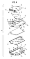
- FIG. 4 is an exploded view of the transmitter module 16. It is noted that this figure depicts the transmitter module 16 of FIG. 3 upside down.
- the transmitter module 16 is mounted as follows. First, the waterproof rubber 22 is placed in the upper body 17. The electronic substrate 21 is placed on the waterproof rubber 22. The lower body 18 is placed over the electronic substrate, and plural projections 18a to 18c formed at the sides of the lower body 18 (projections are also formed at the far sides of the lower body.) are engaged with holes 17a to 17i formed in the sides of the upper body 17, whereby the upper body 17 and the lower body 18 are unified.
- the battery 25 is loaded on the battery cover 24, which is positioned to direct the battery-25 carrying side downward and is placed on the battery receiving hole 23 of the lower body 18.
- a predetermined procedure (described hereinlater) is taken to bring the projections 26 to 28, formed at the lateral faces of the battery cover 24, into engagement with the apertures 31 to 33 formed in at least one pair of walls 29, 30 disposed on the surface of the lower body 18 substantially in parallel to each other, whereby the battery cover 24 and the lower body 18 are unified.
- FIGs. 5A and 5B is an external view of the battery cover 24 and the waterproof seal 34.
- FIG. 5A shows the battery cover 24 as viewed obliquely, the battery cover directing its battery-25 carrying side upward.
- FIG. 5B shows the waterproof seal 34 as viewed in the same direction, the seal being in a state yet to be mounted (or dismounted from the battery cover 24).
- the battery cover 24 is generally formed in one piece of the transversely elongate box shape having a thickness D, thus achieving the required mechanical strength.
- the battery cover has the projections 26 to 28 formed at the two lateral faces of the short sides thereof and is substantially centrally formed with the battery receiving portion 25a shaped like a circular hole for receiving the battery 25 therein.
- the battery cover is further formed with a groove 25b in which the waterproof seal 34 formed from the elastic material such as rubber is mounted.
- the groove 25b is formed in one surface of the battery cover 24 (battery 25 receiving surface) as continuously extended along a circumference of the battery cover, such that the waterproof seal 34 mounted in the groove 25b may provide waterproofing between the battery cover 24 and the lower body 18.
- a part of the waterproof seal 34 (the repulsive ribs 34a to 34c) is so formed as to cover the lateral face of the battery cover 24, at which face the projections 26, 27 are formed.
- the repulsive ribs 34a to 34c play an important role when the battery cover 24 is mounted to the lower body 18.
- FIGs. 6A to 6C are a group of diagrams showing the steps of the procedure of mounting the battery cover 24 to the lower body 18.
- the battery cover 24 with the battery 25 loaded thereon is first inclined in a direction of an arrow P1 and the projections 26, 27 on the one lateral face of the battery cover 24 are inserted in the apertures 31, 32 in the wall 29 of the lower body 18, as shown in FIG. 6A .
- the repulsive ribs 34a to 34c of the waterproof seal 34 are compressively deformed by applying a force in a leftward direction (direction of an arrow P2) as seen in the figure.
- the compressive deformation of the repulsive ribs 34a to 34c provides a minor clearance between the right side of the battery cover 24 as seen in the figure and the wall 30.
- the battery cover 24 is appropriately turned clockwise (direction of an arrow P3) with respect to the drawing surface about the point of engagement between the projections 26, 27 and the apertures 31, 32, as the supporting point so that the battery cover 24 is substantially brought into a horizontal position.
- the clearance between the right side of the battery cover 24 and the wall 30 is eliminated due to the repulsive force of the repulsive ribs 34a to 34c, as shown in FIG. 6C .
- the projection 28 of the battery cover 24 is engaged with the aperture 32 in the wall 30.
- the handheld device 10 is constructed such that the transmitter module 16 mounted in the case portion 13 has the two-piece structure including the upper body 17 and the lower body 18, and that at least the pair of walls 29, 30 are disposed upright on the lower body 18 in the substantial parallel relation and the battery cover 24 with the battery 25 loaded thereon is engaged with the walls 29, 30. Therefore, the device may offer an effect to prevent the electronic substrate 21 from dropping out during the replacement of the battery 25 and to prevent the waterproof seal 34 from being lost.
- the procedure of replacement of the battery 25 may be accomplished simply by inclining the battery cover 24 with a fresh battery 25 loaded thereon and bringing the projections 26, 27 of the battery cover 24 into engagement with the apertures 31, 32 in one wall 29 of the lower body 18 as compressively deforming the repulsive ribs 34a to 34c, followed by engaging the projection 28 of the battery cover 24 with the aperture 33 in the other wall 30 of the lower body 18 as maintaining the repulsive ribs 34a to 34c in compressive deformation.
- the electronic substrate 21 is firmly held between the upper body 17 and the lower body 18. Therefore, the possibility of the electronic substrate 21 dropping out is eliminated.
- the waterproof seal 34 of the embodiment which is equivalent to the O-ring 5 of the related art (see FIG. 8 ), is fitted in the groove 25b of the battery cover 24 and has a part thereof extended to one side of the battery cover 24 and constituting the repulsive ribs 34a to 34c. Therefore, the waterproof seal 34 is also prevented from dropping out during the battery replacement. This eliminates the fear of the waterproof seal being lost.
- the battery cover 24 according to the embodiment has an effect to be reduced in size as compared with the related-art battery cover (e.g., the battery cover 6 shown in FIG. 8 ).
- FIG. 7 is a diagram showing the comparison of the area of the battery cover 24.
- a dimension A of the short side of the battery cover 24 may be at least a diameter B of the battery 25 plus a space C for forming the groove 25b in which the waterproof seal 34 is fitted.
- the related-art battery cover 6 (depicted as circle for convenience) must provide not only a space for mounting the O-ring 5 but also a space for fixing the screw 7, a space for forming the projection 6a and the like. It is therefore unavoidable that the related-art battery cover has a larger dimension than the dimension A of the battery cover 24 of the embodiment.
- the handheld device 10 with the built-in mechanical key is particularly benefited from the merit (reduction of the dimension A) of the battery cover 24 according to the embodiment.
- the reason is as follows.
- the handheld device of this type is required to provide a space for the mechanical key 15 to be accommodated in the handheld device 10. As the dimension A of the battery cover 24 is reduced, it is easier for the device to provide the required space.
Landscapes
- Physics & Mathematics (AREA)
- Chemical Kinetics & Catalysis (AREA)
- Electrochemistry (AREA)
- General Chemical & Material Sciences (AREA)
- Engineering & Computer Science (AREA)
- Manufacturing & Machinery (AREA)
- Chemical & Material Sciences (AREA)
- General Physics & Mathematics (AREA)
- Battery Mounting, Suspending (AREA)
- Selective Calling Equipment (AREA)
- Transmitters (AREA)
- Casings For Electric Apparatus (AREA)
- Lock And Its Accessories (AREA)
Applications Claiming Priority (1)
| Application Number | Priority Date | Filing Date | Title |
|---|---|---|---|
| JP2007000482A JP4849624B2 (ja) | 2007-01-05 | 2007-01-05 | 携帯機 |
Publications (3)
| Publication Number | Publication Date |
|---|---|
| EP1944818A2 true EP1944818A2 (de) | 2008-07-16 |
| EP1944818A3 EP1944818A3 (de) | 2009-04-15 |
| EP1944818B1 EP1944818B1 (de) | 2011-10-19 |
Family
ID=39473171
Family Applications (1)
| Application Number | Title | Priority Date | Filing Date |
|---|---|---|---|
| EP07150035A Not-in-force EP1944818B1 (de) | 2007-01-05 | 2007-12-14 | Handgerät |
Country Status (2)
| Country | Link |
|---|---|
| EP (1) | EP1944818B1 (de) |
| JP (1) | JP4849624B2 (de) |
Cited By (5)
| Publication number | Priority date | Publication date | Assignee | Title |
|---|---|---|---|---|
| GB2473887A (en) * | 2009-09-25 | 2011-03-30 | Askey Computer Corp | Waterproof Battery Casing Fixing Structure |
| CN102005552A (zh) * | 2009-08-31 | 2011-04-06 | 佳能株式会社 | 具有可拆卸且可开闭的盖的电子设备 |
| WO2012089204A1 (de) * | 2010-12-21 | 2012-07-05 | Huf Hülsbeck & Fürst Gmbh & Co. Kg | Elektronischer schlüssel |
| WO2018214234A1 (zh) * | 2017-05-23 | 2018-11-29 | 深圳市大疆创新科技有限公司 | 一种遥控器的电池固定结构及遥控器 |
| CN113728364A (zh) * | 2019-04-29 | 2021-11-30 | 海拉有限双合股份公司 | 用于机动车的电子的钥匙系统 |
Families Citing this family (4)
| Publication number | Priority date | Publication date | Assignee | Title |
|---|---|---|---|---|
| JP5310215B2 (ja) * | 2009-04-13 | 2013-10-09 | パナソニック株式会社 | 携帯送信機 |
| DE102018100715A1 (de) * | 2018-01-15 | 2019-07-18 | Huf Hülsbeck & Fürst Gmbh & Co. Kg | Elektronisches Handgerät, insbesondere Funkschlüssel, mit einer Dichthaube |
| JP2019124040A (ja) * | 2018-01-16 | 2019-07-25 | 株式会社東海理化電機製作所 | 操作装置 |
| JP2019124081A (ja) * | 2018-01-18 | 2019-07-25 | 株式会社東海理化電機製作所 | 電子キー |
Citations (4)
| Publication number | Priority date | Publication date | Assignee | Title |
|---|---|---|---|---|
| JPH09121392A (ja) | 1995-10-26 | 1997-05-06 | Matsushita Electric Ind Co Ltd | 送信器 |
| JP2001339176A (ja) | 2000-05-29 | 2001-12-07 | Alps Electric Co Ltd | 小型電気装置 |
| JP2003090152A (ja) | 2001-09-17 | 2003-03-28 | Alps Electric Co Ltd | キーレスエントリー装置の携帯機 |
| JP2003201781A (ja) | 2002-01-08 | 2003-07-18 | Alps Electric Co Ltd | キーレスエントリの携帯機の防水構造 |
Family Cites Families (10)
| Publication number | Priority date | Publication date | Assignee | Title |
|---|---|---|---|---|
| JPH09331160A (ja) * | 1996-06-12 | 1997-12-22 | Oki Electric Ind Co Ltd | 携帯機器用電池カバー |
| JPH10163888A (ja) * | 1996-11-29 | 1998-06-19 | Denso Corp | 送信機及び自動車用キー |
| JP3614284B2 (ja) * | 1997-09-12 | 2005-01-26 | 株式会社ケンウッド | 電子機器の防水構造 |
| JP3209415B2 (ja) * | 1997-12-24 | 2001-09-17 | 東海興業株式会社 | ケース開口の防水密封構造 |
| JP2000048786A (ja) * | 1998-07-30 | 2000-02-18 | Denso Corp | 電池ケース |
| JP2001221868A (ja) * | 2000-02-07 | 2001-08-17 | Seiko Instruments Inc | 時計ケースの電池ぶた構造 |
| JP4536334B2 (ja) * | 2003-04-09 | 2010-09-01 | 日本碍子株式会社 | 電池カバー及び該電池カバーを用いた電池収納ケース |
| JP2005122917A (ja) * | 2003-10-14 | 2005-05-12 | Mitsutoyo Corp | 収納体、電池収納部、測定器および電子機器 |
| JP4182430B2 (ja) * | 2003-11-28 | 2008-11-19 | オムロン株式会社 | 送信機 |
| JP4426397B2 (ja) * | 2004-08-02 | 2010-03-03 | 矢崎総業株式会社 | 防水コネクタ |
-
2007
- 2007-01-05 JP JP2007000482A patent/JP4849624B2/ja not_active Expired - Fee Related
- 2007-12-14 EP EP07150035A patent/EP1944818B1/de not_active Not-in-force
Patent Citations (4)
| Publication number | Priority date | Publication date | Assignee | Title |
|---|---|---|---|---|
| JPH09121392A (ja) | 1995-10-26 | 1997-05-06 | Matsushita Electric Ind Co Ltd | 送信器 |
| JP2001339176A (ja) | 2000-05-29 | 2001-12-07 | Alps Electric Co Ltd | 小型電気装置 |
| JP2003090152A (ja) | 2001-09-17 | 2003-03-28 | Alps Electric Co Ltd | キーレスエントリー装置の携帯機 |
| JP2003201781A (ja) | 2002-01-08 | 2003-07-18 | Alps Electric Co Ltd | キーレスエントリの携帯機の防水構造 |
Cited By (15)
| Publication number | Priority date | Publication date | Assignee | Title |
|---|---|---|---|---|
| US8752246B2 (en) | 2009-08-31 | 2014-06-17 | Canon Kabushiki Kaisha | Electronic apparatus with detachable and openable lid |
| CN102005552A (zh) * | 2009-08-31 | 2011-04-06 | 佳能株式会社 | 具有可拆卸且可开闭的盖的电子设备 |
| CN102005552B (zh) * | 2009-08-31 | 2013-08-07 | 佳能株式会社 | 具有可拆卸且可开闭的盖的电子设备 |
| GB2473887A (en) * | 2009-09-25 | 2011-03-30 | Askey Computer Corp | Waterproof Battery Casing Fixing Structure |
| EP2902276A1 (de) * | 2010-12-21 | 2015-08-05 | Huf Hülsbeck & Fürst GmbH & Co. KG | Elektronischer Schlüssel |
| CN103237691A (zh) * | 2010-12-21 | 2013-08-07 | 霍弗·霍斯贝克及弗斯特两合公司 | 电子钥匙 |
| WO2012089204A1 (de) * | 2010-12-21 | 2012-07-05 | Huf Hülsbeck & Fürst Gmbh & Co. Kg | Elektronischer schlüssel |
| CN103237691B (zh) * | 2010-12-21 | 2015-12-16 | 霍弗·霍斯贝克及弗斯特两合公司 | 电子钥匙 |
| CN105196968A (zh) * | 2010-12-21 | 2015-12-30 | 霍弗·霍斯贝克及弗斯特两合公司 | 电子钥匙 |
| US9416562B2 (en) | 2010-12-21 | 2016-08-16 | Huf Hulsbeck & Furst Gmbh & Co. Kg | Electronic key |
| CN105196968B (zh) * | 2010-12-21 | 2017-07-11 | 霍弗·霍斯贝克及弗斯特两合公司 | 电子钥匙 |
| WO2018214234A1 (zh) * | 2017-05-23 | 2018-11-29 | 深圳市大疆创新科技有限公司 | 一种遥控器的电池固定结构及遥控器 |
| CN109891619A (zh) * | 2017-05-23 | 2019-06-14 | 深圳市大疆创新科技有限公司 | 一种遥控器的电池固定结构及遥控器 |
| CN113728364A (zh) * | 2019-04-29 | 2021-11-30 | 海拉有限双合股份公司 | 用于机动车的电子的钥匙系统 |
| CN113728364B (zh) * | 2019-04-29 | 2023-11-28 | 海拉有限双合股份公司 | 用于机动车的电子的钥匙系统 |
Also Published As
| Publication number | Publication date |
|---|---|
| JP2008167374A (ja) | 2008-07-17 |
| EP1944818A3 (de) | 2009-04-15 |
| EP1944818B1 (de) | 2011-10-19 |
| JP4849624B2 (ja) | 2012-01-11 |
Similar Documents
| Publication | Publication Date | Title |
|---|---|---|
| EP1944818B1 (de) | Handgerät | |
| US7041924B2 (en) | Housing for an electronic key | |
| AU2012367474B2 (en) | Battery holder | |
| US20080229794A1 (en) | Portable device | |
| US20110247924A1 (en) | Key button mechanism and electronic device using the same | |
| US8531845B2 (en) | Structure of anti tamper case for solid state disk | |
| US7832565B2 (en) | Structure of housing battery etc. | |
| JP2001339176A (ja) | 小型電気装置 | |
| US10843660B2 (en) | Portable device | |
| JP4019298B2 (ja) | プッシュスイッチ内蔵防水回路装置 | |
| JP2002218032A (ja) | 携帯電話のsimカード取り付け構造 | |
| JP3972570B2 (ja) | 送信機 | |
| US8165650B2 (en) | Portable electronic device | |
| US8041408B2 (en) | Battery fastening apparatus and portable terminal using the same | |
| JP4946587B2 (ja) | 携帯機 | |
| US20090151973A1 (en) | Mobile device | |
| KR101255214B1 (ko) | 배터리 개폐구조를 구비한 전자기기 | |
| JP2004339697A (ja) | 電子キー装置 | |
| JP2012144879A (ja) | 携帯機 | |
| KR101417802B1 (ko) | 전자제품의 배터리 커버 개폐 장치 | |
| JP3110649U (ja) | コンピュータマウスの電池カバーの開放と止め合わせ装置 | |
| JP2004241476A (ja) | カード型キーレスリモコン用携帯機 | |
| KR200207373Y1 (ko) | 이동통신 단말기의 배터리 고정장치 | |
| KR200333812Y1 (ko) | 후렛쉬 겸용 체인지 키 | |
| KR101032644B1 (ko) | 외장형 스피커 모듈의 보조 로킹 장치 |
Legal Events
| Date | Code | Title | Description |
|---|---|---|---|
| PUAI | Public reference made under article 153(3) epc to a published international application that has entered the european phase |
Free format text: ORIGINAL CODE: 0009012 |
|
| AK | Designated contracting states |
Kind code of ref document: A2 Designated state(s): AT BE BG CH CY CZ DE DK EE ES FI FR GB GR HU IE IS IT LI LT LU LV MC MT NL PL PT RO SE SI SK TR |
|
| AX | Request for extension of the european patent |
Extension state: AL BA HR MK RS |
|
| RIN1 | Information on inventor provided before grant (corrected) |
Inventor name: SASAKI, SATORUC/O OMRON CORPORATION Inventor name: MATSUSHITA, TAKAOC/O OMRON CORPORATION |
|
| RIN1 | Information on inventor provided before grant (corrected) |
Inventor name: SASAKI, SATORUC/O OMRON CORPORATION Inventor name: MATSUSHITA, TAKAOC/O OMRON CORPORATION |
|
| PUAL | Search report despatched |
Free format text: ORIGINAL CODE: 0009013 |
|
| AK | Designated contracting states |
Kind code of ref document: A3 Designated state(s): AT BE BG CH CY CZ DE DK EE ES FI FR GB GR HU IE IS IT LI LT LU LV MC MT NL PL PT RO SE SI SK TR |
|
| AX | Request for extension of the european patent |
Extension state: AL BA HR MK RS |
|
| 17P | Request for examination filed |
Effective date: 20091015 |
|
| AKX | Designation fees paid |
Designated state(s): DE ES FR GB IT |
|
| RAP1 | Party data changed (applicant data changed or rights of an application transferred) |
Owner name: OMRON AUTOMOTIVE ELECTRONICS CO., LTD. |
|
| GRAP | Despatch of communication of intention to grant a patent |
Free format text: ORIGINAL CODE: EPIDOSNIGR1 |
|
| RIN1 | Information on inventor provided before grant (corrected) |
Inventor name: SASAKI, SATORUC/O OMRON CORPORATION Inventor name: MATSUSHITA, TAKAOC/O OMRON CORPORATION |
|
| GRAS | Grant fee paid |
Free format text: ORIGINAL CODE: EPIDOSNIGR3 |
|
| GRAA | (expected) grant |
Free format text: ORIGINAL CODE: 0009210 |
|
| AK | Designated contracting states |
Kind code of ref document: B1 Designated state(s): DE ES FR GB IT |
|
| REG | Reference to a national code |
Ref country code: GB Ref legal event code: FG4D |
|
| REG | Reference to a national code |
Ref country code: DE Ref legal event code: R096 Ref document number: 602007017990 Country of ref document: DE Effective date: 20111222 |
|
| PLBE | No opposition filed within time limit |
Free format text: ORIGINAL CODE: 0009261 |
|
| STAA | Information on the status of an ep patent application or granted ep patent |
Free format text: STATUS: NO OPPOSITION FILED WITHIN TIME LIMIT |
|
| PG25 | Lapsed in a contracting state [announced via postgrant information from national office to epo] |
Ref country code: IT Free format text: LAPSE BECAUSE OF FAILURE TO SUBMIT A TRANSLATION OF THE DESCRIPTION OR TO PAY THE FEE WITHIN THE PRESCRIBED TIME-LIMIT Effective date: 20111019 |
|
| 26N | No opposition filed |
Effective date: 20120720 |
|
| GBPC | Gb: european patent ceased through non-payment of renewal fee |
Effective date: 20120119 |
|
| PG25 | Lapsed in a contracting state [announced via postgrant information from national office to epo] |
Ref country code: GB Free format text: LAPSE BECAUSE OF NON-PAYMENT OF DUE FEES Effective date: 20120119 |
|
| REG | Reference to a national code |
Ref country code: DE Ref legal event code: R097 Ref document number: 602007017990 Country of ref document: DE Effective date: 20120720 |
|
| REG | Reference to a national code |
Ref country code: DE Ref legal event code: R082 Ref document number: 602007017990 Country of ref document: DE Representative=s name: KILIAN KILIAN & PARTNER, DE Ref country code: DE Ref legal event code: R082 Ref document number: 602007017990 Country of ref document: DE Representative=s name: KILIAN KILIAN & PARTNER MBB PATENTANWAELTE, DE |
|
| PG25 | Lapsed in a contracting state [announced via postgrant information from national office to epo] |
Ref country code: ES Free format text: LAPSE BECAUSE OF FAILURE TO SUBMIT A TRANSLATION OF THE DESCRIPTION OR TO PAY THE FEE WITHIN THE PRESCRIBED TIME-LIMIT Effective date: 20120130 |
|
| REG | Reference to a national code |
Ref country code: DE Ref legal event code: R084 Ref document number: 602007017990 Country of ref document: DE Effective date: 20140717 |
|
| PGFP | Annual fee paid to national office [announced via postgrant information from national office to epo] |
Ref country code: DE Payment date: 20141209 Year of fee payment: 8 |
|
| PGFP | Annual fee paid to national office [announced via postgrant information from national office to epo] |
Ref country code: FR Payment date: 20141208 Year of fee payment: 8 |
|
| REG | Reference to a national code |
Ref country code: DE Ref legal event code: R119 Ref document number: 602007017990 Country of ref document: DE |
|
| REG | Reference to a national code |
Ref country code: FR Ref legal event code: ST Effective date: 20160831 |
|
| PG25 | Lapsed in a contracting state [announced via postgrant information from national office to epo] |
Ref country code: DE Free format text: LAPSE BECAUSE OF NON-PAYMENT OF DUE FEES Effective date: 20160701 |
|
| PG25 | Lapsed in a contracting state [announced via postgrant information from national office to epo] |
Ref country code: FR Free format text: LAPSE BECAUSE OF NON-PAYMENT OF DUE FEES Effective date: 20151231 |