EP1944565A1 - Vorrichtung zur Abwehr von Geschossen, insbesondere Hohlladungsgeschossen - Google Patents
Vorrichtung zur Abwehr von Geschossen, insbesondere Hohlladungsgeschossen Download PDFInfo
- Publication number
- EP1944565A1 EP1944565A1 EP07405007A EP07405007A EP1944565A1 EP 1944565 A1 EP1944565 A1 EP 1944565A1 EP 07405007 A EP07405007 A EP 07405007A EP 07405007 A EP07405007 A EP 07405007A EP 1944565 A1 EP1944565 A1 EP 1944565A1
- Authority
- EP
- European Patent Office
- Prior art keywords
- braid
- wires
- projectiles
- mesh
- projectile
- Prior art date
- Legal status (The legal status is an assumption and is not a legal conclusion. Google has not performed a legal analysis and makes no representation as to the accuracy of the status listed.)
- Granted
Links
Images
Classifications
-
- F—MECHANICAL ENGINEERING; LIGHTING; HEATING; WEAPONS; BLASTING
- F41—WEAPONS
- F41H—ARMOUR; ARMOURED TURRETS; ARMOURED OR ARMED VEHICLES; MEANS OF ATTACK OR DEFENCE, e.g. CAMOUFLAGE, IN GENERAL
- F41H5/00—Armour; Armour plates
- F41H5/013—Mounting or securing armour plates
-
- F—MECHANICAL ENGINEERING; LIGHTING; HEATING; WEAPONS; BLASTING
- F41—WEAPONS
- F41H—ARMOUR; ARMOURED TURRETS; ARMOURED OR ARMED VEHICLES; MEANS OF ATTACK OR DEFENCE, e.g. CAMOUFLAGE, IN GENERAL
- F41H11/00—Defence installations; Defence devices
- F41H11/02—Anti-aircraft or anti-guided missile or anti-torpedo defence installations or systems
-
- F—MECHANICAL ENGINEERING; LIGHTING; HEATING; WEAPONS; BLASTING
- F41—WEAPONS
- F41H—ARMOUR; ARMOURED TURRETS; ARMOURED OR ARMED VEHICLES; MEANS OF ATTACK OR DEFENCE, e.g. CAMOUFLAGE, IN GENERAL
- F41H5/00—Armour; Armour plates
- F41H5/02—Plate construction
- F41H5/023—Armour plate, or auxiliary armour plate mounted at a distance of the main armour plate, having cavities at its outer impact surface, or holes, for deflecting the projectile
- F41H5/026—Slat armour; Nets
-
- F—MECHANICAL ENGINEERING; LIGHTING; HEATING; WEAPONS; BLASTING
- F41—WEAPONS
- F41H—ARMOUR; ARMOURED TURRETS; ARMOURED OR ARMED VEHICLES; MEANS OF ATTACK OR DEFENCE, e.g. CAMOUFLAGE, IN GENERAL
- F41H7/00—Armoured or armed vehicles
- F41H7/02—Land vehicles with enclosing armour, e.g. tanks
- F41H7/04—Armour construction
-
- Y—GENERAL TAGGING OF NEW TECHNOLOGICAL DEVELOPMENTS; GENERAL TAGGING OF CROSS-SECTIONAL TECHNOLOGIES SPANNING OVER SEVERAL SECTIONS OF THE IPC; TECHNICAL SUBJECTS COVERED BY FORMER USPC CROSS-REFERENCE ART COLLECTIONS [XRACs] AND DIGESTS
- Y10—TECHNICAL SUBJECTS COVERED BY FORMER USPC
- Y10S—TECHNICAL SUBJECTS COVERED BY FORMER USPC CROSS-REFERENCE ART COLLECTIONS [XRACs] AND DIGESTS
- Y10S428/00—Stock material or miscellaneous articles
- Y10S428/911—Penetration resistant layer
Definitions
- the invention relates to a device for the defense and protection of projectiles, in particular shaped charge projectiles according to the preamble of claim 1.
- this inventive braid provides protection against shell bullets with shaped charge projectiles or similar braiding heads.
- the present invention has for its object to provide a device of the type mentioned above, which is advantageous in terms of weight, creates better visibility for the crew and provides high security for the object to be protected.
- the inventive device for the defense of projectiles in particular shaped charge projectiles whose protective wall or protective walls consists of a preferably diamond-shaped mesh-forming mesh or exist, compared to the conventional protective grids much easier, and their construction (assembly and disassembly) is much easier.
- Significantly fewer connecting parts are needed, especially if wires, cables or rods are used for attachment through edge stitches and / or through loop-type end elements.
- the device is easily transportable by aircraft, for example, because the wire mesh can be folded or rolled up. Thanks to their material properties, these special braids can also be prestressed without any plastic deformation, which facilitates installation and optimizes their function on the vehicles.
- this device offers a high level of security in the sense that such projectiles are disturbed by these braids and thus become virtually unexploded. They lose their effect because this normally occurring upon impact liquid metal jet does not occur or is greatly disturbed.
- the view is e.g. for the combat vehicle driver or for the crew much better than with the conventional protective grids.
- Fig.1 is shown as an example of a projectile, in particular shaped charge projectiles, such as grenade projectiles, to be protected object a combat vehicle 1, which is equipped with an inventive device 2 for defense of projectiles.
- the device 2 has several around the combat vehicle 1 arranged around protective walls, which consist of a wire mesh 3 according to the invention.
- wire mesh 3 is a diagonal braid
- the diamond-shaped mesh 4 forms and is preferably braided from steel wires.
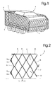
- FIG. 2 A particularly preferred embodiment of the wire mesh 3 is in Fig. 2 illustrated.
- the wire mesh 3 is braided from helically bent wires 5, 6, 7, 8, etc., which have a pitch angle ⁇ (preferably 25 ° to 35 °).
- ⁇ preferably 25 ° to 35 °.
- the wire mesh 3 has a three-dimensional structure with a thickness which is several times the wire thickness.
- the wires 5 to 8 are provided at their ends with loops or knots 5a, 6a, 7a, 8a, etc., and connected by these in pairs hinged together.
- the wire mesh 3 be easily folded or rolled up for storage and transport.
- this wire mesh with a center wire between the points of contact of the individual coil. It is also a braid with a training, which is formed of two or more wires or wire strands of steel (see EP-A-1 628 790 ).
- a wire, a rope, a rod 10 or another frame element can be looped into the helically bent edge wire 5, by means of which the wire mesh 3 can be stretched in its longitudinal extension, and then the combat vehicle 1 are attached.
- appropriate fasteners could directly hold the edge wire loops 5 '.
- the wire mesh 3 can also be fastened laterally by means of similar elements (wires, cables, rods or directly engaging fastening means) guided by the loops or knots 5a, 6a, 7a, 8a, etc.
- the individual protective walls of the device 2 can also be connected by wire mesh sections with a e.g. Be limited from frame formed frame and the device 2 are assembled from these.
- Fasteners may also be formed by ropes, wires or strands.
- the slightly round, conical, concave and / or convex clamping on a surface is also advantageous.
- the size of the diamond-shaped meshes 4, in particular their incircle diameter B ( Fig. 2 ) is chosen so that it substantially corresponds to the maximum diameter of the shell bullets to be defended or something smaller or larger than this diameter.
- the garnet can penetrate through the mesh 4, but is disturbed by touching the mesh and thereby in a sense "damaged" so that it does not come to the intended explosion or this is done only in reduced mass.
- the three-dimensional structure of the wire mesh (3) contributes to the probability that the projectile touches the wire mesh (3) is greater than in a flat, only one of the wire thickness corresponding wire mesh, especially in obliquely arriving Einschdorfn.
- the inventive device for repelling mortar shells is compared to the conventional protective grids much easier, and their construction (assembly and disassembly) is considerably easier, since much fewer connecting parts are needed, especially if the above, by the Randmaschen and / or by the loop-type end elements guided wires, ropes or rods can be used for attachment.
- the device is easily transportable by aircraft, for example, because the wire mesh can be folded or rolled up.
- the view for example for the combat vehicle driver or for the crew much better than in the conventional protective grids.
- the wire mesh can be arranged closer to the object, this due to the bias in the mesh and due to the optimal stress-strain behavior and the deformation behavior of the special braid, so that for example in a combat vehicle, its overall width can be reduced, which facilitates the use eg in cities.
- the device according to the invention can be used to defend grenade projectiles for the protection of many objects other than combat vehicles or mobile objects in general.
- strategically important objects such as monitored driveways with the inventive device be equipped (as would under certain circumstances a single wall would be sufficient) or other objects are protected only temporarily.
- the wire mesh 3 is particularly advantageous to manufacture the wire mesh 3 from wires that consist of a high-strength steel with a nominal strength between 1,000 and 3,000 N / mm 2 , which may also be spring steel wires according to DIN standard 17223. This allows much thinner wires to be used for the same strength, which reduces the likelihood of a garnet bullet striking the wire directly on the front of the firing member, resulting in a full-blown explosion.
- the total weight of the device according to the invention is further reduced and the visibility is further improved, for example for the combat vehicle driver or for the crew.
- the mesh size of a braid 3 can also be chosen so small that the braid exerts a protective shield function. In a collision of a garnet projectile always or at least for the most part a detonation arises. But due to a sufficient distance of the braid to the object 1, damage to the object can be prevented or greatly reduced.
- the mesh size or the Inn Vietnamese bemesser the braid is advantageously less than 30 mm in such a case.
- wire mesh 3 instead of individual, preferably helically bent wires and wire elements such as wire strands, wire ropes, wire bundles or the like could be used for the wire mesh 3.
- the mesh 3 can basically consist of rectangular, triangular, polygonal and / or diamond-shaped meshes 4. It could also have a honeycomb or hexagonal formation as in garden horticulture. It is also possible that from plastics and / or parts of plastics and / or parts of combined materials such braid structures are formed or otherwise produced, which then can give the already mentioned mesh forms.
- braiding may also be understood as a braid which is designed as a net, as for example in the document EP-A-0 679 457 is set forth.
Landscapes
- Engineering & Computer Science (AREA)
- General Engineering & Computer Science (AREA)
- Aviation & Aerospace Engineering (AREA)
- Radar, Positioning & Navigation (AREA)
- Remote Sensing (AREA)
- Aiming, Guidance, Guns With A Light Source, Armor, Camouflage, And Targets (AREA)
- Braiding, Manufacturing Of Bobbin-Net Or Lace, And Manufacturing Of Nets By Knotting (AREA)
Abstract
Description
- Die Erfindung betrifft eine Vorrichtung zur Abwehr und zum Schutz von Geschossen, insbesondere Hohlladungsgeschossen gemäss dem Oberbegriff des Anspruches 1.
- Es ist bekannt, zur Abwehr von Hohlladungsgeschossen beispielsweise an Kampffahrzeugen eine Art Schutzgitter rund herum bzw. mehrere gitterartige Schutzwände aus Stahlprofilen und Stahllamellen und/oder ähnlichen geschweissten Stahlelementen anzubringen, deren Zweck ist, die Geschosse zu stören und dadurch ausser Funktion zu setzen oder zumindest ihre volle Auswirkung zu verhindern. Derartige Vorrichtungen sind relativ massiv, ihre Montage nicht einfach (es werden viele Verbindungsteile benötigt) und sie beeinträchtigen oft die Sicht und reduzieren durch ihr relativ grosses Gewicht die Nutzlasten dieser Fahrzeuge.
- Insbesondere bietet dieses erfindungsgemässe Geflecht Schutz gegen Granatgeschosse mit Hohlladungsgeschossen oder ähnlichen Geflechtsköpfen.
- Weitere Anwendungsmöglichkeiten dieser speziellen Schutzgeflechte gibt es aber auch im Bereich von beispielsweise Container-Schutz, Immobilienschutz, Perimeterschutz, Schutz von maritimen Einrichtungen, Schiffen, Plattformen, Verstärkung von Fensterfronten, etc.
- Der vorliegenden Erfindung liegt die Aufgabe zugrunde, eine Vorrichtung der eingangs genannten Art zu schaffen, die gewichtmässig vorteilhaft ist, bessere Sichtverhältnisse für die Besatzung schafft und eine hohe Sicherheit für das zu schützende Objekt bietet.
- Diese Aufgabe wird erfindungsgemäss durch eine Vorrichtung mit den Merkmalen des Anspruches 1 gelöst.
- Weitere bevorzugte Ausgestaltungen der erfindungsgemässen Vorrichtung bilden den Gegenstand der abhängigen Ansprüche.
- Die erfindungsgemässe Vorrichtung zur Abwehr von Geschossen, insbesondere Hohlladungsgeschossen, deren Schutzwand bzw. Schutzwände aus einem vorzugsweise rautenförmige Maschen bildenden Geflecht besteht bzw. bestehen, ist im Vergleich zu den herkömmlichen Schutzgittern wesentlich leichter, und ihr Aufbau (Montage und Demontage) ist erheblich einfacher. Es werden wesentlich weniger Verbindungsteile gebraucht, insbesondere wenn für die Befestigung durch Randmaschen und/oder durch schlaufenartigen Endelemente geführte Drähte, Seile oder Stangen verwendet werden. Die Vorrichtung ist zum Beispiel mit dem Flugzeug leicht transportierbar, da das Drahtgeflecht zusammengelegt oder zusammengerollt werden kann. Ebenfalls können diese speziellen Geflechte dank ihrer Materialbeschaffenheit vorgespannt werden, ohne dass es gleich zu plastischen Verformungen kommt, was den Einbau erleichtert und die Funktion auf den Fahrzeugen optimiert.
- Nebst dem bietet diese Vorrichtung eine hohe Sicherheit in dem Sinne, dass solche Geschosse durch diese Geflechte gestört und dadurch quasi zu Blindgängern werden. Sie verlieren dabei ihre Wirkung, weil dieser normalerweise beim Aufprall entstehende Flüssigmetallstrahl nicht auftritt oder stark gestört wird.
- Zudem wird - wenn beispielsweise ein Kraftfahrzeug mit der erfindungsgemässen Vorrichtung geschützt wird - die Sicht z.B. für den Kampffahrzeugfahrer oder für die Besatzung wesentlich besser als bei den herkömmlichen Schutzgittern.
- Die Erfindung wird nachfolgend anhand der Zeichnung näher erläutert. Es zeigen:
- Fig. 1
- ein Kampffahrzeug als ein Ausführungsbeispiel eines vor Granatgeschossen zu schützenden Objekts, ausgerüstet mit einer erfindungsgemässen Vorrichtung zur Abwehr von Geschossen; und
- Fig. 2
- einen Teil der Vorrichtung zur Abwehr von Geschossen nach
Fig. 1 in einem vergrösserten Massstab. - In
Fig.1 ist als Beispiel eines vor Geschossen, insbesondere Hohlladungsgeschossen, wie beispielsweise Granatgeschossen, zu schützenden Objektes ein Kampffahrzeug 1 dargestellt, das mit einer erfindungsgemässen Vorrichtung 2 zur Abwehr von Geschossen ausgerüstet ist. Die Vorrichtung 2 weist mehrere rund um das Kampffahrzeug 1 herum angeordnete Schutzwände auf, die erfindungsgemäss aus einem Drahtgeflecht 3 bestehen. Beim Drahtgeflecht 3 handelt es sich um ein Diagonalgeflecht, das rautenförmige Maschen 4 bildet und vorzugsweise aus Stahldrähten geflochten ist. - Eine besonders bevorzugte Ausführungsform des Drahtgeflechtes 3 ist in
Fig. 2 veranschaulicht. GemässFig. 2 ist das Drahtgeflecht 3 aus wendelförmig gebogenen Drähten 5, 6, 7, 8 etc. geflochten, die einen Steigungswinkel α (vorzugsweise 25° bis 35°) aufweisen. Es werden jeweils zwei benachbarte Drähte 5, 6; 6, 7; 7, 8 etc. im Bereich A ihrer Biegungen zueinander gelenkig gehalten. Das Drahtgeflecht 3 weist eine dreidimensionale Struktur mit einer Dicke auf, die ein Mehrfaches der Drahtdicke beträgt. - Die Drähte 5 bis 8 sind an ihren Enden mit Schlaufen oder Knoten 5a, 6a, 7a, 8a etc. versehen und durch diese paarweise miteinander gelenkig verbunden.
- Durch die gelenkige Verbindung der benachbarten Drahtpaare sowohl in den Anlenkungsbereichen A als auch in den Endbereichen kann das Drahtgeflecht 3 problemlos für die Lagerung und den Transport zusammengelegt bzw. zusammengerollt werden.
- Es ist auch möglich, dieses Drahtgeflecht mit einem Mitteldraht zwischen den Berührungspunkten der einzelnen Wendel auszubilden. Es eignet sich zudem ein Geflecht mit einer Ausbildung, welches aus zwei oder mehreren Drähten oder Drahtlitzen aus Stahl gebildet ist (siehe
EP-A- 1 628 790 ). - Am oberen und am unteren Ende des Drahtgeflechtes 3 kann in den wendelförmig gebogenen Randdraht 5 je ein Draht, ein Seil, eine Stange 10 oder ein anderes Rahmenelement eingeschlauft werden, mittels denen das Drahtgeflecht 3 in seiner Längsstreckung gespannt werden kann, und die dann am Kampffahrzeug 1 befestigt werden. Für die Befestigung am Kampffahrzeug 1 könnten allerdings auch entsprechende Befestigungsmittel direkt die Randdrahtschlaufen 5' halten. Das Drahtgeflecht 3 kann auch seitlich mittels ähnlichen, durch die Schlaufen oder Knoten 5a, 6a, 7a, 8a etc. geführten Elementen (Drähte, Seile, Stangen oder direkt eingreifende Befestigungsmittel) befestigt werden.
- Die einzelnen Schutzwände der Vorrichtung 2 können auch durch Drahtgeflechtabschnitte mit einem z.B. aus Stangen gebildeten Rahmen begrenzt sein und die Vorrichtung 2 aus diesen zusammenmontiert werden. Befestigungselemente können auch durch Seile, Drähte oder Litzen ausgebildet sein. Je nach Anwendung ist zudem auch das leicht runde, konische, konkave und/oder konvexe Aufspannen auf eine Oberfläche vorteilhaft.
- Die Grösse der rautenförmigen Maschen 4, insbesondere ihr Inkreisdurchmesser B (
Fig. 2 ) ist so gewählt, dass sie im wesentlichen dem maximalen Durchmesser der abzuwehrenden Granatgeschosse entspricht oder etwas kleiner oder grösser ist als dieser Durchmesser. Das Granatgeschoss kann zwar durch die Masche 4 hindurchdringen, wird jedoch durch Berührung des Geflechts gestört und dabei im gewissen Sinne "beschädigt", so dass es zu der vorgesehenen Explosion gar nicht kommt oder diese nur im reduzierten Masse erfolgt. Die dreidimensionale Struktur des Drahtgeflechtes (3) trägt dazu bei, dass insbesondere bei schräg eintreffenden Einschüssen die Wahrscheinlichkeit, dass das Geschoss das Drahtgeflecht (3) berührt, grösser ist als bei einem flachen, lediglich eine der Drahtdicke entsprechende Dicke aufweisenden Drahtgeflecht. - Die erfindungsgemässe Vorrichtung zur Abwehr von Granatgeschossen ist im Vergleich zu den herkömmlichen Schutzgittern wesentlich leichter, und ihr Aufbau (Montage und Demontage) ist erheblich einfacher, da wesentlich weniger Verbindungsteile gebraucht werden, insbesondere wenn die vorstehend erwähnten, durch die Randmaschen und/oder durch die schlaufenartigen Endelemente geführten Drähte, Seile oder Stangen für die Befestigung verwendet werden.
- Die Vorrichtung ist zum Beispiel mit dem Flugzeug leicht transportierbar, da das Drahtgeflecht zusammengelegt oder zusammengerollt werden kann. Zudem wird die Sicht z.B. für den Kampffahrzeugfahrer oder für die Besatzung wesentlich besser als bei den herkömmlichen Schutzgittern. Das Drahtgeflecht kann näher zum Objekt angeordnet werden, dies aufgrund der Vorspannung im Geflecht sowie aufgrund des optimalen Spannungs-Dehnungsverhaltens sowie des Deformationsverhaltens des Spezialgeflechtes, so dass beispielsweise bei einem Kampffahrzeug seine Gesamtbreite reduziert werden kann, was den Einsatz z.B. in Städten erleichtert.
- Selbstverständlich kann die erfindungsgemässe Vorrichtung zur Abwehr von Granatgeschossen zum Schutze von vielen anderen Objekten als von Kampffahrzeugen oder fahrbaren Objekten generell eingesetzt werden. So können z.B. auch strategisch wichtige Objekte wie beispielsweise überwachte Einfahrten mit der erfindungsgemässen Vorrichtung ausgerüstet sein (da würde unter Umständen eine einzige Schutzwand ausreichen) oder andere Objekte auch nur vorübergehend geschützt werden.
- Es ist besonders vorteilhaft, das Drahtgeflecht 3 aus Drähten herzustellen, die aus einem hochfesten Stahl mit einer Nennfestigkeit zwischen 1'000 und 3'000 N/mm2 bestehen, wobei es sich auch um Federstahldrähte nach der DIN-Norm 17223 handeln kann. Dies erlaubt, bei gleicher Festigkeit wesentlich dünnere Drähte zu verwenden, wodurch die Wahrscheinlichkeit, dass ein Granatgeschoss frontal mit dem Zündteil direkt auf einen Draht auftrifft und folglich doch zu einer Vollexplosion kommt, vermindert wird. Zudem wird das Gesamtgewicht der erfindungsgemässen Vorrichtung noch weiter reduziert und die Sicht z.B. für den Kampffahrzeugfahrer oder für die Besatzung noch weiter verbessert.
- Die Maschengrösse eines Geflechtes 3 kann aber auch derart gering gewählt werden, dass das Geflecht eine Schutzschildfunktion ausübt. Bei einem Aufprall eines Granatgeschosses entsteht dann immer oder zumindest grösstenteils eine Detonation. Aber aufgrund eines ausreichenden Abstandes des Geflechtes zum Objekt 1 kann eine Beschädigung vom Objekt verhindert bzw. stark verringert werden. Die Maschengrösse respektive der Innkreisdurchmesser des Geflechtes beträgt in einem solchen Falle vorteilhaft weniger als 30 mm.
- Anstelle von einzelnen, vorzugsweise wendelförmig gebogenen Drähten könnten für das Drahtgeflecht 3 auch Drahtelemente wie Drahtlitzen, Drahtseile, Drahtbündel oder ähnlichem verwendet werden.
- Das Geflecht 3 kann grundsätzlich aus rechteckigen, dreieckigen, polygon- und/oder rautenförmigen Maschen 4 bestehen. Es könnte auch eine wabenförmige oder hexagonale Ausbildung wie bei Gartenhagnetzen aufweisen. Es ist weiter möglich, dass aus Kunststoffen und/oder Teilen von Kunststoffen und/oder Teilen von kombinierten Werkstoffen solche Geflechtsstrukturen nachgeformt oder andersartig hergestellt werden, welche dann auch die bereits erwähnten Maschenformen ergeben können.
- Als Geflecht kann grundsätzlich auch ein solches verstanden werden, welches als Netz ausgebildet ist, wie dies zum Beispiel in der Druckschrift
EP-A-0 679 457 dargelegt ist.
Claims (13)
- Vorrichtung zur Abwehr und zum Schutz von Geschossen, insbesondere Hohlladungsgeschossen, mit mindestens einer gitterartigen Schutzwand zum Schutze eines Objektes (1) durch Ablenkung, Teilauslösung, Auslösung und/oder Beschädigung der Geschosse, dadurch gekennzeichnet, dass
die Schutzwand aus einem Maschen (4) bildenden Geflecht (3) besteht. - Vorrichtung nach Anspruch 1, dadurch gekennzeichnet, dass das Geflecht (3) aus rechteckigen, dreieckigen, hexagonalen, polygon- und/ oder rautenförmigen Maschen (4) besteht.
- Vorrichtung nach Anspruch 1, dadurch gekennzeichnet, dass die Maschen (4) eine Inkreisdurchmesser (B) aufweisen, die im wesentlichen dem Geschossdurchmesser entspricht oder etwas kleiner bzw. leicht grösser ist als dieser Durchmesser.
- Vorrichtung nach einem der Ansprüche 1 bis 3, dadurch gekennzeichnet, dass das Geflecht (3) aus Stahldrähten, Seilen, Litzen und/oder aus Kunststoff geflochten ist oder aus Kunststoffen so hergestellt ist, dass sich eine Art Geflechtsstruktur ergibt.
- Vorrichtung nach einem der Ansprüche 1 bis 4, dadurch gekennzeichnet, dass das Geflecht (3) aus wendelförmig gebogenen Drähten (5, 6, 7, 8) geflochten ist, wobei jeweils zwei benachbarte wendelförmige Drähte (5, 6; 6, 7; 7, 8) zueinander gelenkig gehalten sind, wobei die Drähte (5, 6, 7, 8) an ihren Enden mit Schlaufen oder Knoten (5a, 6a, 7a, 8a) versehen sind, und die miteinander verflochtenen wendelförmigen Drähte (5, 6, 7, 8) paarweise über diese Endelemente (5a, 6a, 7a, 8a) miteinander gelenkig verbunden sind.
- Vorrichtung nach Anspruch 5, dadurch gekennzeichnet, dass das Geflecht (3) eine Dicke aufweist, die wenigstens mehr als das Doppelte der Drahtdicke beträgt.
- Vorrichtung nach Anspruch 5 oder 6, dadurch gekennzeichnet, dass die Drähte des Geflechtes (3) aus einem hochfesten Stahl mit einer Nennfestigkeit zwischen 900 und 3'000 N/mm2 bestehen.
- Vorrichtung nach einem der Ansprüche 1 bis 7, dadurch gekennzeichnet, dass das Geflecht (3) mehrere Schutzwände für das Objekt (1) bildet und am Objekt (1) befestigbar ist.
- Vorrichtung nach Anspruch 8, dadurch gekennzeichnet, dass das Geflecht (3) an einem fahrbaren Objekt (1) montierbar ist.
- Vorrichtung nach Anspruch 8 oder 9, dadurch gekennzeichnet, dass durch Randmaschen des Geflechtes (3) und/oder durch die die wendelförmigen Drähte (5, 6, 7, 8) paarweise verbindende Endelemente (5a, 6a, 7a, 8a) Drähte, Seile oder Stangen (10) geführt sind, über welche das Geflecht (3) am Objekt (1) befestigbar ist.
- Vorrichtung nach Anspruch 8 oder 9, dadurch gekennzeichnet, dass die einzelnen Schutzwände durch Geflechtabschnitte gebildet sind, die durch eine aus Stangen gebildeten Rahmen begrenzt sind, wobei die Stangen durch Randmaschen des Geflechtes (3) und durch die die wendelförmigen Drähte (5, 6, 7, 8) paarweise verbindende Endelemente (5a, 6a, 7a, 8a) hindurchgeführt sind.
- Vorrichtung nach Anspruch 1, dadurch gekennzeichnet, dass die Maschengrösse derart gering ist, dass das Geflecht eine Schutzschildfunktion ausübt, so dass bei einem Aufprall eines Granatgeschosses eine Detonation, Auslösung oder Teilauslösung des Geschosses erfolgt, dass aber aufgrund eines ausreichenden Abstandes des Geflechtes zum Objekt (1) eine Beschädigung von letzterem verhindert bzw. stark verringert werden kann.
- Vorrichtung nach Anspruch 12, dadurch gekennzeichnet, dass die Maschengrösse weniger oder leicht mehr als 30 mm beträgt.
Priority Applications (5)
| Application Number | Priority Date | Filing Date | Title |
|---|---|---|---|
| EP07405007A EP1944565B1 (de) | 2007-01-10 | 2007-01-10 | Vorrichtung zur Abwehr von Hohlladungsgeschossen |
| ES07405007T ES2388935T3 (es) | 2007-01-10 | 2007-01-10 | Dispositivo para defenderse contra proyectiles de carga hueca |
| PL07405007T PL1944565T3 (pl) | 2007-01-10 | 2007-01-10 | Urządzenie do obrony przed pociskami kumulacyjnymi |
| DK07405007.1T DK1944565T3 (da) | 2007-01-10 | 2007-01-10 | Indretning til forsvar mod hulladningsprojektiler |
| US11/668,124 US7975594B2 (en) | 2007-01-10 | 2007-01-29 | Device for defense from projectiles, particularly shaped charge projectiles |
Applications Claiming Priority (1)
| Application Number | Priority Date | Filing Date | Title |
|---|---|---|---|
| EP07405007A EP1944565B1 (de) | 2007-01-10 | 2007-01-10 | Vorrichtung zur Abwehr von Hohlladungsgeschossen |
Publications (2)
| Publication Number | Publication Date |
|---|---|
| EP1944565A1 true EP1944565A1 (de) | 2008-07-16 |
| EP1944565B1 EP1944565B1 (de) | 2012-06-13 |
Family
ID=38121887
Family Applications (1)
| Application Number | Title | Priority Date | Filing Date |
|---|---|---|---|
| EP07405007A Not-in-force EP1944565B1 (de) | 2007-01-10 | 2007-01-10 | Vorrichtung zur Abwehr von Hohlladungsgeschossen |
Country Status (5)
| Country | Link |
|---|---|
| US (1) | US7975594B2 (de) |
| EP (1) | EP1944565B1 (de) |
| DK (1) | DK1944565T3 (de) |
| ES (1) | ES2388935T3 (de) |
| PL (1) | PL1944565T3 (de) |
Cited By (4)
| Publication number | Priority date | Publication date | Assignee | Title |
|---|---|---|---|---|
| DE102009052821A1 (de) | 2009-11-13 | 2011-05-19 | Krauss-Maffei Wegmann Gmbh & Co. Kg | Schutzelement zum Schutz gegen Hohlladungsgeschosse, Schutzabdeckung für ein Schutzelement, geschütztes Objekt sowie Verfahren zum Schutz eines Objektes |
| WO2011057628A1 (de) | 2009-11-13 | 2011-05-19 | Krauss-Maffei Wegmann Gmbh & Co. Kg | Schutzelement zum schutz gegen hohlladungsgeschosse, schutzabdeckung für ein schutzelement, geschütztes objekt sowie verfahren zum schutz eines objektes |
| DE102009052820A1 (de) | 2009-11-13 | 2011-05-26 | Krauss-Maffei Wegmann Gmbh & Co. Kg | Schutzabdeckung für Schutzelemente zum Schutz gegen Hohlladungsgeschosse, Schutzelement mit einer Schutzabdeckung sowie mit einem Schutzelement geschütztes Objekt |
| EP3769030A4 (de) * | 2018-02-19 | 2022-04-06 | Robert Levy | Schutzkabelnetzsystem (pcns) |
Families Citing this family (30)
| Publication number | Priority date | Publication date | Assignee | Title |
|---|---|---|---|---|
| US20090217811A1 (en) * | 2006-01-17 | 2009-09-03 | David William Leeming | Textile armour |
| US7900548B2 (en) | 2006-02-09 | 2011-03-08 | Foster Miller, Inc. | Protection system including a net |
| US7866250B2 (en) | 2006-02-09 | 2011-01-11 | Foster-Miller, Inc. | Vehicle protection system |
| NL2000406C2 (nl) * | 2006-12-22 | 2008-06-24 | Tno | Werkwijze en inrichting voor het beschermen van objecten tegen raket-aangedreven granaten (RPG's). |
| US8011285B2 (en) * | 2008-04-16 | 2011-09-06 | Foster-Miller, Inc. | Vehicle and structure shield |
| US8443709B2 (en) * | 2008-04-16 | 2013-05-21 | QinetiQ North America, Inc. | Vehicle and structure shield hard point |
| US8453552B2 (en) | 2008-04-16 | 2013-06-04 | QinetiQ North America, Inc. | Method of designing an RPG shield |
| US8607685B2 (en) | 2008-04-16 | 2013-12-17 | QinetiQ North America, Inc. | Load sharing hard point net |
| US8615851B2 (en) | 2008-04-16 | 2013-12-31 | Foster-Miller, Inc. | Net patching devices |
| US8468927B2 (en) | 2008-04-16 | 2013-06-25 | QinetiQ North America, Inc. | Vehicle and structure shield with a cable frame |
| US8245620B2 (en) * | 2008-04-16 | 2012-08-21 | QinetiQ North America, Inc. | Low breaking strength vehicle and structure shield net/frame arrangement |
| US20110079135A1 (en) | 2008-04-16 | 2011-04-07 | Farinella Michael D | Vehicle and structure shield net/frame arrangement |
| US8464627B2 (en) | 2008-04-16 | 2013-06-18 | QinetiQ North America, Inc. | Vehicle and structure shield with improved hard points |
| WO2011142784A2 (en) * | 2009-12-15 | 2011-11-17 | Force Protection Technologies, Inc. | Apparatus for extending and retracting an armor system for defeating high energy projectiles |
| US8677882B2 (en) | 2010-09-08 | 2014-03-25 | QinetiQ North America, Inc. | Vehicle and structure shield with flexible frame |
| FR2970773B1 (fr) * | 2011-01-21 | 2015-02-20 | Nexter Systems | Grille de protection |
| JP5685475B2 (ja) * | 2011-04-11 | 2015-03-18 | 株式会社ケィズ・アロー | 防護装置 |
| US20120291616A1 (en) * | 2011-05-17 | 2012-11-22 | Andrewartha Michael I | Shield kits for projectile protection |
| US8297193B1 (en) | 2011-07-08 | 2012-10-30 | Foster-Miller, Inc. | Surrogate RPG |
| FR2978540B1 (fr) * | 2011-07-29 | 2013-07-26 | Nexter Systems | Grille de protection pour ouvrant |
| GB2494457A (en) * | 2011-09-12 | 2013-03-13 | Ten Cate Advanced Armour Uk Ltd | Armour module for a vehicle |
| WO2013043216A1 (en) * | 2011-09-22 | 2013-03-28 | QinetiQ North America, Inc. | Vehicle and structure shield with a cable frame |
| CH706178B1 (de) * | 2012-02-24 | 2016-02-15 | Geobrugg Ag | Netz, insbesondere für den Schutz-, Sicherheits-, Gewässerzucht- oder Architekturbereich, sowie eine Vorrichtung zur Herstellung des Netzes. |
| US8573125B1 (en) * | 2012-07-13 | 2013-11-05 | Blast Control Systems, L.L.C. | Blast control blanket |
| US8813631B1 (en) | 2013-02-13 | 2014-08-26 | Foster-Miller, Inc. | Vehicle and structure film/hard point shield |
| US9835417B1 (en) * | 2014-11-18 | 2017-12-05 | Ronald J. Kay | RPG shield netting and related manufacturing methods |
| DE102017101754B3 (de) * | 2017-01-30 | 2018-05-17 | Geobrugg Ag | Drahtgeflecht und Verfahren zur Herstellung einer Wendel für ein Drahtgeflecht |
| US10215536B2 (en) | 2017-04-21 | 2019-02-26 | Foster-Miller, Inc. | Hard point net |
| CN106969670A (zh) * | 2017-04-30 | 2017-07-21 | 曹伟 | 拦截巡航导弹防护网 |
| IL271158B2 (en) * | 2019-12-03 | 2024-04-01 | Cohen Michael | Composite shutter/mesh armor |
Citations (7)
| Publication number | Priority date | Publication date | Assignee | Title |
|---|---|---|---|---|
| DE218246C (de) * | ||||
| US1385897A (en) | 1918-11-19 | 1921-07-26 | Tresidder Tolmie John | Device for decapping armor-piercing shells |
| GB517911A (en) * | 1938-11-16 | 1940-02-12 | Kornelis Jacobus Huineman | Bullet-proof armour |
| DE691067C (de) * | 1935-06-16 | 1940-05-16 | Trapezdraht Sieb G M B H | Aus einem Drahtgeflecht bestehender Schutzschild gegen Geschosse |
| WO1992000496A1 (en) * | 1990-06-26 | 1992-01-09 | Passive Barriers Ltd. | Yielding barriers |
| EP1628790B1 (de) * | 2004-06-08 | 2006-09-27 | Fatzer Ag | Schutznetz, insbesondere für einen steinschlagschutz oder für eine böschungssicherung |
| WO2006135432A2 (en) * | 2004-10-21 | 2006-12-21 | Mititech Llc | Barrier system for protection against low-flying projectiles |
Family Cites Families (25)
| Publication number | Priority date | Publication date | Assignee | Title |
|---|---|---|---|---|
| US1286261A (en) * | 1916-03-17 | 1918-12-03 | Giovanni Emanuele Elia | Ship. |
| US1657915A (en) * | 1927-07-09 | 1928-01-31 | Calamita Pietro | Protective device for vessels |
| US2323853A (en) * | 1942-10-14 | 1943-07-06 | Simeone Louis | Ship guard |
| US2954964A (en) * | 1958-11-24 | 1960-10-04 | Thomas E O'haffey | Wire fences having means to render them impervious to light and air |
| AT293233B (de) * | 1968-11-02 | 1971-09-27 | Keller & Knappich Gmbh | Wasserwerferfahrzeug |
| US3769142A (en) * | 1970-12-04 | 1973-10-30 | Mc Donnell Douglas Corp | Non-woven locked ply composite structure |
| US3964197A (en) * | 1974-06-24 | 1976-06-22 | Tucker Robert F | Versatile outdoor sign |
| US3942598A (en) * | 1974-08-19 | 1976-03-09 | Council Henry M | Non-hostage vehicle |
| US4787289A (en) * | 1988-01-15 | 1988-11-29 | Duer Morris J | Bullet trap |
| CA2145829C (en) * | 1994-04-08 | 2003-03-18 | Bernhard Eicher | Method and apparatus for producing a retaining net |
| US5524694A (en) * | 1994-09-21 | 1996-06-11 | H. G. Maybeck Co., Inc. | Protective screen for vehicle window |
| US6363867B1 (en) * | 1997-03-07 | 2002-04-02 | Maoz Betzer Tsilevich | Structural protective system and method |
| US20040221712A1 (en) * | 1999-03-20 | 2004-11-11 | Stewart Ricky William | Ballistic-resistant laminate assemblies and panels |
| US6481782B2 (en) * | 2001-04-10 | 2002-11-19 | Greg Bond | Bullet resistant exterior vehicle body protector |
| US7820565B2 (en) * | 2001-05-03 | 2010-10-26 | Barrday Inc. | Densely woven quasi-unidirectional fabric for ballistic applications |
| US6568310B2 (en) * | 2001-10-25 | 2003-05-27 | Timothy W. Morgan | Lightweight armored panels and doors |
| US20060065111A1 (en) * | 2002-04-17 | 2006-03-30 | Henry James J M | Armor system |
| US6841492B2 (en) * | 2002-06-07 | 2005-01-11 | Honeywell International Inc. | Bi-directional and multi-axial fabrics and fabric composites |
| US6647855B1 (en) * | 2002-09-30 | 2003-11-18 | The United States Of America As Represented By The United States National Aeronautics And Space Administration | Apparatus and method for deploying a hypervelocity shield |
| US7100490B2 (en) * | 2003-07-01 | 2006-09-05 | Muller Jr Robert L | Body armor |
| US7076898B1 (en) * | 2003-08-26 | 2006-07-18 | Hunt Randall C | Method and apparatus for fence advertisement |
| US6973864B1 (en) * | 2003-12-19 | 2005-12-13 | The Cooper Union For The Advancement Of Science And Art | Protective structure and protective system |
| CH697125A5 (de) * | 2004-11-26 | 2008-05-15 | Fatzer Ag | Ringförmiges Element sowie ein Auffangnetz bestehend aus derartigen Elementen. |
| CH698850B1 (de) * | 2005-12-09 | 2009-11-13 | Fatzer Ag | Schutzgeflecht, insbesondere für einen Steinschlagschutz oder für die Sicherung einer Erdoberflächenschicht. |
| US7866250B2 (en) * | 2006-02-09 | 2011-01-11 | Foster-Miller, Inc. | Vehicle protection system |
-
2007
- 2007-01-10 DK DK07405007.1T patent/DK1944565T3/da active
- 2007-01-10 ES ES07405007T patent/ES2388935T3/es active Active
- 2007-01-10 EP EP07405007A patent/EP1944565B1/de not_active Not-in-force
- 2007-01-10 PL PL07405007T patent/PL1944565T3/pl unknown
- 2007-01-29 US US11/668,124 patent/US7975594B2/en not_active Expired - Fee Related
Patent Citations (7)
| Publication number | Priority date | Publication date | Assignee | Title |
|---|---|---|---|---|
| DE218246C (de) * | ||||
| US1385897A (en) | 1918-11-19 | 1921-07-26 | Tresidder Tolmie John | Device for decapping armor-piercing shells |
| DE691067C (de) * | 1935-06-16 | 1940-05-16 | Trapezdraht Sieb G M B H | Aus einem Drahtgeflecht bestehender Schutzschild gegen Geschosse |
| GB517911A (en) * | 1938-11-16 | 1940-02-12 | Kornelis Jacobus Huineman | Bullet-proof armour |
| WO1992000496A1 (en) * | 1990-06-26 | 1992-01-09 | Passive Barriers Ltd. | Yielding barriers |
| EP1628790B1 (de) * | 2004-06-08 | 2006-09-27 | Fatzer Ag | Schutznetz, insbesondere für einen steinschlagschutz oder für eine böschungssicherung |
| WO2006135432A2 (en) * | 2004-10-21 | 2006-12-21 | Mititech Llc | Barrier system for protection against low-flying projectiles |
Cited By (7)
| Publication number | Priority date | Publication date | Assignee | Title |
|---|---|---|---|---|
| DE102009052821A1 (de) | 2009-11-13 | 2011-05-19 | Krauss-Maffei Wegmann Gmbh & Co. Kg | Schutzelement zum Schutz gegen Hohlladungsgeschosse, Schutzabdeckung für ein Schutzelement, geschütztes Objekt sowie Verfahren zum Schutz eines Objektes |
| WO2011057628A1 (de) | 2009-11-13 | 2011-05-19 | Krauss-Maffei Wegmann Gmbh & Co. Kg | Schutzelement zum schutz gegen hohlladungsgeschosse, schutzabdeckung für ein schutzelement, geschütztes objekt sowie verfahren zum schutz eines objektes |
| DE102009052820A1 (de) | 2009-11-13 | 2011-05-26 | Krauss-Maffei Wegmann Gmbh & Co. Kg | Schutzabdeckung für Schutzelemente zum Schutz gegen Hohlladungsgeschosse, Schutzelement mit einer Schutzabdeckung sowie mit einem Schutzelement geschütztes Objekt |
| DE102009052821B4 (de) * | 2009-11-13 | 2012-05-24 | Krauss-Maffei Wegmann Gmbh & Co. Kg | Schutzelement zum Schutz gegen Hohlladungsgeschosse, Schutzabdeckung für ein Schutzelement, geschütztes Objekt sowie Verfahren zum Schutz eines Objektes |
| DE102009052820B4 (de) * | 2009-11-13 | 2012-06-14 | Krauss-Maffei Wegmann Gmbh & Co. Kg | Schutzabdeckung für Schutzelemente zum Schutz gegen Hohlladungsgeschosse, Schutzelement mit einer Schutzabdeckung sowie mit einem Schutzelement geschütztes Objekt |
| EP3018442A1 (de) | 2009-11-13 | 2016-05-11 | Krauss-Maffei Wegmann GmbH & Co. KG | Schutzabdeckung für ein schutzelement |
| EP3769030A4 (de) * | 2018-02-19 | 2022-04-06 | Robert Levy | Schutzkabelnetzsystem (pcns) |
Also Published As
| Publication number | Publication date |
|---|---|
| ES2388935T3 (es) | 2012-10-19 |
| PL1944565T3 (pl) | 2012-11-30 |
| US20080164379A1 (en) | 2008-07-10 |
| DK1944565T3 (da) | 2012-08-13 |
| US7975594B2 (en) | 2011-07-12 |
| EP1944565B1 (de) | 2012-06-13 |
Similar Documents
| Publication | Publication Date | Title |
|---|---|---|
| EP1944565B1 (de) | Vorrichtung zur Abwehr von Hohlladungsgeschossen | |
| EP2817455B1 (de) | Netz, insbesondere für den schutz-, sicherheits-, gewässerzucht- oder architekturbereich, sowie eine vorrichtung zur herstellung des netzes | |
| DE3049425C2 (de) | Aufprall-Schutz-Bauteil | |
| EP1795279B1 (de) | Schutznetz, insbesondere für einen Steinschlagschutz oder für die Sicherung einer Erdoberflächenschicht | |
| EP2249980B1 (de) | Vorrichtung für das explosionsumformen | |
| EP2642030B1 (de) | Schutznetz | |
| DE102009043196A1 (de) | Abwehrsystem | |
| EP2456920A2 (de) | Sicherheitsnetz auf wasser oder auf grundboden | |
| AT270394B (de) | Sprengschutzmatte | |
| DE102012004188A1 (de) | Verfahren zur Behandlung eines aus Polyethylen mit ultrahohem Molekulargewicht hergestellten Netzes | |
| EP2806245B1 (de) | Anordnung zum Schutz eines Objekts gegen anfliegende Projektile | |
| DE2448404A1 (de) | Zielanordnung fuer bogenschiessen | |
| DE2107233A1 (de) | Auffangzaun, insbesondere fur Lawinen, Steinschlag oder Langholz rutschungen | |
| EP2053340B1 (de) | Flächiges Verbundpanzerungselement | |
| DE3324153A1 (de) | Objektschutzgitter | |
| DE102010037202B4 (de) | Bauwerk, insbesondere Bauwerk eines Kernkraftwerkes | |
| CH710263A2 (de) | Auffangnetz insbesondere für Steinschlag- oder Lawinenverbauungen. | |
| DE1534538A1 (de) | Sicherheitszaun | |
| CH711370A2 (de) | Schutznetz, vorzugsweise zum Auskleiden von Tunnelwänden im Minenbau oder für die Sicherung von Erdoberflächenschichten. | |
| DE8915976U1 (de) | Stahldrahtseilnetz für Steinschlag- und Lawinenverbauungen | |
| CH708809B1 (de) | Schutznetz-Installation, insbesondere für eine Böschungssicherung, mit einem Schutznetz, sowie eine dazugehörige Krallplatte. | |
| DE1178328B (de) | Geschichtete Panzerplatte | |
| DE102010028933A1 (de) | Schutzwand | |
| DE102007050658A1 (de) | Flächiges Verbundpanzerungselement | |
| DE10231607B4 (de) | Panzerungselement |
Legal Events
| Date | Code | Title | Description |
|---|---|---|---|
| PUAI | Public reference made under article 153(3) epc to a published international application that has entered the european phase |
Free format text: ORIGINAL CODE: 0009012 |
|
| AK | Designated contracting states |
Kind code of ref document: A1 Designated state(s): AT BE BG CH CY CZ DE DK EE ES FI FR GB GR HU IE IS IT LI LT LU LV MC NL PL PT RO SE SI SK TR |
|
| AX | Request for extension of the european patent |
Extension state: AL BA HR MK RS |
|
| 17P | Request for examination filed |
Effective date: 20081217 |
|
| 17Q | First examination report despatched |
Effective date: 20090119 |
|
| AKX | Designation fees paid |
Designated state(s): AT BE BG CH CY CZ DE DK EE ES FI FR GB GR HU IE IS IT LI LT LU LV MC NL PL PT RO SE SI SK TR |
|
| GRAP | Despatch of communication of intention to grant a patent |
Free format text: ORIGINAL CODE: EPIDOSNIGR1 |
|
| RTI1 | Title (correction) |
Free format text: DEVICE FOR DEFLECTING HOLLOW CHARGE PROJECTILES |
|
| GRAS | Grant fee paid |
Free format text: ORIGINAL CODE: EPIDOSNIGR3 |
|
| GRAA | (expected) grant |
Free format text: ORIGINAL CODE: 0009210 |
|
| AK | Designated contracting states |
Kind code of ref document: B1 Designated state(s): AT BE BG CH CY CZ DE DK EE ES FI FR GB GR HU IE IS IT LI LT LU LV MC NL PL PT RO SE SI SK TR |
|
| REG | Reference to a national code |
Ref country code: GB Ref legal event code: FG4D Free format text: NOT ENGLISH |
|
| REG | Reference to a national code |
Ref country code: CH Ref legal event code: EP Ref country code: AT Ref legal event code: REF Ref document number: 562180 Country of ref document: AT Kind code of ref document: T Effective date: 20120615 |
|
| REG | Reference to a national code |
Ref country code: CH Ref legal event code: NV Representative=s name: LUCHS & PARTNER AG PATENTANWAELTE |
|
| REG | Reference to a national code |
Ref country code: IE Ref legal event code: FG4D Free format text: LANGUAGE OF EP DOCUMENT: GERMAN |
|
| REG | Reference to a national code |
Ref country code: DE Ref legal event code: R096 Ref document number: 502007010039 Country of ref document: DE Effective date: 20120809 |
|
| REG | Reference to a national code |
Ref country code: DK Ref legal event code: T3 |
|
| REG | Reference to a national code |
Ref country code: NL Ref legal event code: VDEP Effective date: 20120613 |
|
| REG | Reference to a national code |
Ref country code: ES Ref legal event code: FG2A Ref document number: 2388935 Country of ref document: ES Kind code of ref document: T3 Effective date: 20121019 |
|
| PG25 | Lapsed in a contracting state [announced via postgrant information from national office to epo] |
Ref country code: FI Free format text: LAPSE BECAUSE OF FAILURE TO SUBMIT A TRANSLATION OF THE DESCRIPTION OR TO PAY THE FEE WITHIN THE PRESCRIBED TIME-LIMIT Effective date: 20120613 Ref country code: CY Free format text: LAPSE BECAUSE OF FAILURE TO SUBMIT A TRANSLATION OF THE DESCRIPTION OR TO PAY THE FEE WITHIN THE PRESCRIBED TIME-LIMIT Effective date: 20120613 Ref country code: SE Free format text: LAPSE BECAUSE OF FAILURE TO SUBMIT A TRANSLATION OF THE DESCRIPTION OR TO PAY THE FEE WITHIN THE PRESCRIBED TIME-LIMIT Effective date: 20120613 Ref country code: LT Free format text: LAPSE BECAUSE OF FAILURE TO SUBMIT A TRANSLATION OF THE DESCRIPTION OR TO PAY THE FEE WITHIN THE PRESCRIBED TIME-LIMIT Effective date: 20120613 |
|
| REG | Reference to a national code |
Ref country code: LT Ref legal event code: MG4D Effective date: 20120613 |
|
| PG25 | Lapsed in a contracting state [announced via postgrant information from national office to epo] |
Ref country code: GR Free format text: LAPSE BECAUSE OF FAILURE TO SUBMIT A TRANSLATION OF THE DESCRIPTION OR TO PAY THE FEE WITHIN THE PRESCRIBED TIME-LIMIT Effective date: 20120914 Ref country code: SI Free format text: LAPSE BECAUSE OF FAILURE TO SUBMIT A TRANSLATION OF THE DESCRIPTION OR TO PAY THE FEE WITHIN THE PRESCRIBED TIME-LIMIT Effective date: 20120613 Ref country code: LV Free format text: LAPSE BECAUSE OF FAILURE TO SUBMIT A TRANSLATION OF THE DESCRIPTION OR TO PAY THE FEE WITHIN THE PRESCRIBED TIME-LIMIT Effective date: 20120613 |
|
| REG | Reference to a national code |
Ref country code: PL Ref legal event code: T3 |
|
| PG25 | Lapsed in a contracting state [announced via postgrant information from national office to epo] |
Ref country code: EE Free format text: LAPSE BECAUSE OF FAILURE TO SUBMIT A TRANSLATION OF THE DESCRIPTION OR TO PAY THE FEE WITHIN THE PRESCRIBED TIME-LIMIT Effective date: 20120613 Ref country code: RO Free format text: LAPSE BECAUSE OF FAILURE TO SUBMIT A TRANSLATION OF THE DESCRIPTION OR TO PAY THE FEE WITHIN THE PRESCRIBED TIME-LIMIT Effective date: 20120613 Ref country code: SK Free format text: LAPSE BECAUSE OF FAILURE TO SUBMIT A TRANSLATION OF THE DESCRIPTION OR TO PAY THE FEE WITHIN THE PRESCRIBED TIME-LIMIT Effective date: 20120613 Ref country code: IS Free format text: LAPSE BECAUSE OF FAILURE TO SUBMIT A TRANSLATION OF THE DESCRIPTION OR TO PAY THE FEE WITHIN THE PRESCRIBED TIME-LIMIT Effective date: 20121013 Ref country code: CZ Free format text: LAPSE BECAUSE OF FAILURE TO SUBMIT A TRANSLATION OF THE DESCRIPTION OR TO PAY THE FEE WITHIN THE PRESCRIBED TIME-LIMIT Effective date: 20120613 |
|
| PG25 | Lapsed in a contracting state [announced via postgrant information from national office to epo] |
Ref country code: PT Free format text: LAPSE BECAUSE OF FAILURE TO SUBMIT A TRANSLATION OF THE DESCRIPTION OR TO PAY THE FEE WITHIN THE PRESCRIBED TIME-LIMIT Effective date: 20121015 |
|
| PLBI | Opposition filed |
Free format text: ORIGINAL CODE: 0009260 |
|
| PG25 | Lapsed in a contracting state [announced via postgrant information from national office to epo] |
Ref country code: NL Free format text: LAPSE BECAUSE OF FAILURE TO SUBMIT A TRANSLATION OF THE DESCRIPTION OR TO PAY THE FEE WITHIN THE PRESCRIBED TIME-LIMIT Effective date: 20120613 |
|
| 26 | Opposition filed |
Opponent name: AMSAFE BRIDPORT LIMITED Effective date: 20130301 |
|
| PLAX | Notice of opposition and request to file observation + time limit sent |
Free format text: ORIGINAL CODE: EPIDOSNOBS2 |
|
| REG | Reference to a national code |
Ref country code: DE Ref legal event code: R026 Ref document number: 502007010039 Country of ref document: DE Effective date: 20130301 |
|
| BERE | Be: lapsed |
Owner name: FATZER A.G. DRAHTSEILFABRIK Effective date: 20130131 |
|
| PG25 | Lapsed in a contracting state [announced via postgrant information from national office to epo] |
Ref country code: BG Free format text: LAPSE BECAUSE OF FAILURE TO SUBMIT A TRANSLATION OF THE DESCRIPTION OR TO PAY THE FEE WITHIN THE PRESCRIBED TIME-LIMIT Effective date: 20120913 |
|
| PLBB | Reply of patent proprietor to notice(s) of opposition received |
Free format text: ORIGINAL CODE: EPIDOSNOBS3 |
|
| PG25 | Lapsed in a contracting state [announced via postgrant information from national office to epo] |
Ref country code: MC Free format text: LAPSE BECAUSE OF NON-PAYMENT OF DUE FEES Effective date: 20130131 |
|
| REG | Reference to a national code |
Ref country code: IE Ref legal event code: MM4A |
|
| PG25 | Lapsed in a contracting state [announced via postgrant information from national office to epo] |
Ref country code: BE Free format text: LAPSE BECAUSE OF NON-PAYMENT OF DUE FEES Effective date: 20130131 |
|
| PG25 | Lapsed in a contracting state [announced via postgrant information from national office to epo] |
Ref country code: IE Free format text: LAPSE BECAUSE OF NON-PAYMENT OF DUE FEES Effective date: 20130110 |
|
| PLBP | Opposition withdrawn |
Free format text: ORIGINAL CODE: 0009264 |
|
| PLBD | Termination of opposition procedure: decision despatched |
Free format text: ORIGINAL CODE: EPIDOSNOPC1 |
|
| PLBM | Termination of opposition procedure: date of legal effect published |
Free format text: ORIGINAL CODE: 0009276 |
|
| STAA | Information on the status of an ep patent application or granted ep patent |
Free format text: STATUS: OPPOSITION PROCEDURE CLOSED |
|
| 27C | Opposition proceedings terminated |
Effective date: 20140602 |
|
| PG25 | Lapsed in a contracting state [announced via postgrant information from national office to epo] |
Ref country code: HU Free format text: LAPSE BECAUSE OF FAILURE TO SUBMIT A TRANSLATION OF THE DESCRIPTION OR TO PAY THE FEE WITHIN THE PRESCRIBED TIME-LIMIT; INVALID AB INITIO Effective date: 20070110 Ref country code: LU Free format text: LAPSE BECAUSE OF NON-PAYMENT OF DUE FEES Effective date: 20130110 |
|
| REG | Reference to a national code |
Ref country code: FR Ref legal event code: PLFP Year of fee payment: 10 |
|
| PGFP | Annual fee paid to national office [announced via postgrant information from national office to epo] |
Ref country code: TR Payment date: 20160203 Year of fee payment: 10 Ref country code: DE Payment date: 20160119 Year of fee payment: 10 Ref country code: DK Payment date: 20160122 Year of fee payment: 10 Ref country code: IT Payment date: 20160122 Year of fee payment: 10 Ref country code: CH Payment date: 20160126 Year of fee payment: 10 Ref country code: ES Payment date: 20160122 Year of fee payment: 10 |
|
| PGFP | Annual fee paid to national office [announced via postgrant information from national office to epo] |
Ref country code: PL Payment date: 20160127 Year of fee payment: 10 Ref country code: AT Payment date: 20160120 Year of fee payment: 10 Ref country code: FR Payment date: 20160121 Year of fee payment: 10 Ref country code: GB Payment date: 20160122 Year of fee payment: 10 |
|
| REG | Reference to a national code |
Ref country code: DE Ref legal event code: R119 Ref document number: 502007010039 Country of ref document: DE |
|
| REG | Reference to a national code |
Ref country code: DK Ref legal event code: EBP Effective date: 20170131 |
|
| REG | Reference to a national code |
Ref country code: CH Ref legal event code: PL |
|
| REG | Reference to a national code |
Ref country code: AT Ref legal event code: MM01 Ref document number: 562180 Country of ref document: AT Kind code of ref document: T Effective date: 20170110 |
|
| GBPC | Gb: european patent ceased through non-payment of renewal fee |
Effective date: 20170110 |
|
| REG | Reference to a national code |
Ref country code: FR Ref legal event code: ST Effective date: 20170929 |
|
| PG25 | Lapsed in a contracting state [announced via postgrant information from national office to epo] |
Ref country code: FR Free format text: LAPSE BECAUSE OF NON-PAYMENT OF DUE FEES Effective date: 20170131 Ref country code: AT Free format text: LAPSE BECAUSE OF NON-PAYMENT OF DUE FEES Effective date: 20170110 Ref country code: LI Free format text: LAPSE BECAUSE OF NON-PAYMENT OF DUE FEES Effective date: 20170131 Ref country code: CH Free format text: LAPSE BECAUSE OF NON-PAYMENT OF DUE FEES Effective date: 20170131 |
|
| PG25 | Lapsed in a contracting state [announced via postgrant information from national office to epo] |
Ref country code: GB Free format text: LAPSE BECAUSE OF NON-PAYMENT OF DUE FEES Effective date: 20170110 Ref country code: DE Free format text: LAPSE BECAUSE OF NON-PAYMENT OF DUE FEES Effective date: 20170801 |
|
| PG25 | Lapsed in a contracting state [announced via postgrant information from national office to epo] |
Ref country code: DK Free format text: LAPSE BECAUSE OF NON-PAYMENT OF DUE FEES Effective date: 20170131 |
|
| PG25 | Lapsed in a contracting state [announced via postgrant information from national office to epo] |
Ref country code: IT Free format text: LAPSE BECAUSE OF NON-PAYMENT OF DUE FEES Effective date: 20170110 |
|
| PG25 | Lapsed in a contracting state [announced via postgrant information from national office to epo] |
Ref country code: ES Free format text: LAPSE BECAUSE OF NON-PAYMENT OF DUE FEES Effective date: 20170111 |
|
| PG25 | Lapsed in a contracting state [announced via postgrant information from national office to epo] |
Ref country code: PL Free format text: LAPSE BECAUSE OF NON-PAYMENT OF DUE FEES Effective date: 20170110 |
|
| REG | Reference to a national code |
Ref country code: ES Ref legal event code: FD2A Effective date: 20181119 |
|
| PG25 | Lapsed in a contracting state [announced via postgrant information from national office to epo] |
Ref country code: TR Free format text: LAPSE BECAUSE OF NON-PAYMENT OF DUE FEES Effective date: 20170110 |