EP1936767B1 - Einrichtung zur kabelunterstützung - Google Patents
Einrichtung zur kabelunterstützung Download PDFInfo
- Publication number
- EP1936767B1 EP1936767B1 EP06780958.2A EP06780958A EP1936767B1 EP 1936767 B1 EP1936767 B1 EP 1936767B1 EP 06780958 A EP06780958 A EP 06780958A EP 1936767 B1 EP1936767 B1 EP 1936767B1
- Authority
- EP
- European Patent Office
- Prior art keywords
- cable
- supporting
- opening
- guide member
- spherical
- Prior art date
- Legal status (The legal status is an assumption and is not a legal conclusion. Google has not performed a legal analysis and makes no representation as to the accuracy of the status listed.)
- Not-in-force
Links
- 238000003780 insertion Methods 0.000 claims description 4
- 230000037431 insertion Effects 0.000 claims description 4
- 238000007599 discharging Methods 0.000 claims description 3
- 230000002093 peripheral effect Effects 0.000 claims description 3
- 238000006073 displacement reaction Methods 0.000 description 12
- 238000010276 construction Methods 0.000 description 8
- 238000005452 bending Methods 0.000 description 4
- 238000010586 diagram Methods 0.000 description 4
- 230000010485 coping Effects 0.000 description 3
- 239000000428 dust Substances 0.000 description 3
- 239000004576 sand Substances 0.000 description 3
- XLYOFNOQVPJJNP-UHFFFAOYSA-N water Substances O XLYOFNOQVPJJNP-UHFFFAOYSA-N 0.000 description 3
- 239000011347 resin Substances 0.000 description 2
- 229920005989 resin Polymers 0.000 description 2
- 238000004891 communication Methods 0.000 description 1
- 230000000694 effects Effects 0.000 description 1
- 239000011796 hollow space material Substances 0.000 description 1
- 238000009434 installation Methods 0.000 description 1
- 230000002452 interceptive effect Effects 0.000 description 1
- 238000004519 manufacturing process Methods 0.000 description 1
- 238000004804 winding Methods 0.000 description 1
Images


Classifications
-
- H—ELECTRICITY
- H02—GENERATION; CONVERSION OR DISTRIBUTION OF ELECTRIC POWER
- H02G—INSTALLATION OF ELECTRIC CABLES OR LINES, OR OF COMBINED OPTICAL AND ELECTRIC CABLES OR LINES
- H02G11/00—Arrangements of electric cables or lines between relatively-movable parts
-
- B—PERFORMING OPERATIONS; TRANSPORTING
- B60—VEHICLES IN GENERAL
- B60R—VEHICLES, VEHICLE FITTINGS, OR VEHICLE PARTS, NOT OTHERWISE PROVIDED FOR
- B60R16/00—Electric or fluid circuits specially adapted for vehicles and not otherwise provided for; Arrangement of elements of electric or fluid circuits specially adapted for vehicles and not otherwise provided for
- B60R16/02—Electric or fluid circuits specially adapted for vehicles and not otherwise provided for; Arrangement of elements of electric or fluid circuits specially adapted for vehicles and not otherwise provided for electric constitutive elements
- B60R16/0207—Wire harnesses
- B60R16/0215—Protecting, fastening and routing means therefor
-
- H—ELECTRICITY
- H02—GENERATION; CONVERSION OR DISTRIBUTION OF ELECTRIC POWER
- H02G—INSTALLATION OF ELECTRIC CABLES OR LINES, OR OF COMBINED OPTICAL AND ELECTRIC CABLES OR LINES
- H02G11/00—Arrangements of electric cables or lines between relatively-movable parts
- H02G11/006—Arrangements of electric cables or lines between relatively-movable parts using extensible carrier for the cable, e.g. self-coiling spring
-
- Y—GENERAL TAGGING OF NEW TECHNOLOGICAL DEVELOPMENTS; GENERAL TAGGING OF CROSS-SECTIONAL TECHNOLOGIES SPANNING OVER SEVERAL SECTIONS OF THE IPC; TECHNICAL SUBJECTS COVERED BY FORMER USPC CROSS-REFERENCE ART COLLECTIONS [XRACs] AND DIGESTS
- Y10—TECHNICAL SUBJECTS COVERED BY FORMER USPC
- Y10T—TECHNICAL SUBJECTS COVERED BY FORMER US CLASSIFICATION
- Y10T403/00—Joints and connections
- Y10T403/32—Articulated members
- Y10T403/32606—Pivoted
- Y10T403/32631—Universal ball and socket
Definitions
- the present invention relates to a cable supporting device and is particularly designed to support a cable spanning between a slide door of a vehicle and a vehicle body in such a manner as to be able to follow the cable when the cable changes its angle in vertical, transverse and oblique directions as the slide door is opened and closed.
- Electrical parts such as a power window and a door lock are installed in a door of an automotive vehicle, and a cable (door harness) for constantly feeding power is connected with these electrical parts.
- the cable is arranged to extend toward the vehicle body and connected with a power-supply side cable in the vehicle body.
- the door is a slide door, it may move in vertical direction normal to a sliding direction and transverse direction at the time of being closed and opened.
- the angle of the cable spanning between the slide door and the vehicle body changes with respect to transverse and vertical directions.
- the cable spanning between the slide door and the vehicle body is fixed to and supported on the vehicle body, but it is necessary to provide a mechanism capable of following the angular change of the cable in vertical, transverse and oblique directions in the supporting device.
- Japanese Unexamined Patent Publication No. 2004-40862 proposes a device shown in FIG. 7 as a cable supporting device of this type.
- a cable spanning between a vehicle body and a slide door is covered by a cable guide 2 formed by connecting a plurality of link members 1, one end of the cable guide 2 is connected with a supporting member 3 fixed to the vehicle body and the cable inserted through the cable guide 2 is passed through the supporting member 3.
- connection pin P1 extending in horizontal direction
- the link member 1 is swingably connected with the supporting member 3 in vertical direction so as to follow the angular change of the cable in vertical direction.
- connection pins P2 extending in vertical direction so as to be able to follow the angular change of the cable in transverse direction.
- a mechanism can follow the angular change of the cable in vertical and transverse directions.
- An amount of vertical angular change of a slide door of an automotive vehicle differs depending on the vehicle type. Further, the slide door is constructed to obliquely move with respect to vertical direction as being slid from a closed state to an open state. This angle of inclination also differs depending on the vehicle type. Further, the mounting position and mounting angle of the cable supporting device on the vehicle also differ.
- the link member 1 a at the leading end of the cable guide 2 is swingably connected with the cable supporting member 3 in vertical direction, and the link members 1 successively connected with the vertically swingable link member 1a in forward and backward directions are swingably connected in transverse direction.
- the cable passing through the link member 1 a at the leading end is swung in vertical direction, but cannot be swung in transverse direction, and a transverse swinging movement is caused by the link member 1 connected with the link member 1a and the following link members 1. Therefore, the cable can make no transverse swinging movement at a position proximate to the cable supporting member 3, thereby being twisted in the link members.
- the present invention was developed to solve the above problems of document 1 and an object thereof is to provide a cable supporting device capable of coping with amounts of vertical and transverse angular changes of a cable despite their magnitudes, coping with angular changes of the cable in oblique directions and, hence, sufficiently coping with angular changes of the cable even if the mounting position and mounting angle thereof on a vehicle slightly differ.
- the invention is directed to a cable supporting device for supporting a cable arranged between a vehicle body and a movable member movably connected to the vehicle body, comprising:
- the cable is supported by being inserted through the hollow portion of the rotatably supported guide member as described above, thereby being able to change its angle over wide ranges in vertical, transverse and oblique directions.
- the supporting device of the present invention can cope with any angular changes in vertical, transverse and oblique directions over wide ranges, it is not necessary to consider the mounting position and mounting angle of the supporting device on a vehicle or the like and assemblability at the time of manufacturing can be improved.
- the cable supporting device of the present invention is suitably used in the case of being mounted on the vehicle body and/or a slide door to support the cable arranged between the movable member, which is the slide door, and the vehicle body.
- the cable is bent by about 90° upon being arranged in the vehicle body and the door by way of the supporting device from the position of arrangement between the slide door and the vehicle body. Therefore, the first and second openings of the guide member are preferably located at orthogonal positions spaced apart by 90°.
- the cable is covered by a corrugate tube between the slide door and the vehicle body in some cases other than by the covering member made of the chained link member disclosed in the prior art.
- the corrugate tube can follow the cable not only in transverse direction, but also in vertical direction, but its angular ranges are limited. Therefore, by supporting the cable covered by the corrugate tube in the vehicle body and/or the slide door using the cable supporting device of the present invention, the supporting device can follow the angular changes of the cable over wider ranges.
- the corrugate tube instead of the covering member in the form of the chained link member in this way, it is preferable to restrict the bending direction of the corrugate tube to prevent the corrugate tube from coming into contact with an external interfering member, for example, by forming ribs extending in lengthwise direction in a specified section to project at a required position of the outer circumferential surface of the corrugate tube.
- leading-end link rotates only in directions different from the other links in patent document 1, whereas the leading-end link rotates in the same directions as the other links in the case of using the supporting device of the present invention.
- an arrangement space can be reduced.
- the spherical guide member as the guide member itself rotates in the supporting device of the present invention, the arrangement space can be further reduced if the spherical guide member is rotated in the same direction as the links.
- the cable is preferably fixed to the second supporting member by providing the second supporting member with a tubular portion communicating with the second opening of the spherical guide member, and providing a fixing piece for the cable projecting from the upper end of the tubular portion.
- the cable since the cable is fixed to the second supporting member, the cable can be prevented from slackening to get entangled or jammed in the spherical guide member, wherefore the spherical guide member can smoothly rotate.
- tubular portion may be provided separately from a tightly holding portion of the spherical guide member and the separate tubular portion may be assembled with the tightly holding portion.
- a plurality of locking pieces project from the peripheral edge of the spherical opening of either one of the first and second supporting members while being circumferentially spaced apart, whereas locking holes engageable with the locking pieces are formed in the other of the first and second supporting members, and the first and second supporting members are connected with the spherical guide member surrounded and held by the locking pieces.
- the spherical guide member and the first and second supporting members at the opposite sides can be integrally assembled beforehand and fixed to the vehicle body in this state.
- assemblability can be improved.
- the spherical guide member can be so stably tightly held as to be rotatable by the first and second supporting members.
- fixing holes are formed at the opposite sides of the spherical opening in each of the first and second supporting members and brought into communication, and fastening members are inserted therethrough to fix the supporting device to the vehicle body and/or the movable member by means of the fastening members.
- the supporting device can be easily fixed to the vehicle body and/or the movable member using the fastening members and the first and second supporting members can be connected with an increased force by such fixation using the fastening members. Therefore, the first and second supporting members can be more firmly connected.
- a supporting surface of the supporting member for rotatably supporting the arcuate surface of the guide member is preferably formed with grooves for discharging foreign matters.
- the cable supporting device of the present invention constructed as described above can be optimally used as the one for a cable arranged between a vehicle body and a slide door, and the angular change of the cable can be followed by the rotation of the spherical guide member as the slide door is opened and closed by fixing the supporting member rotatably tightly holding the guide member to the vehicle body and/or the door.
- the cable may be a flat cable in which conductive members are arranged in parallel and laminated with an insulating resin sheet or an insulated round wire.
- the cable is supported by being inserted through the hollow portion of the guide member rotatably supported by the supporting member.
- the angle of the cable changes, such an angular change can be followed by the rotation of the spherical guide member, wherefore no excessive load such as a twist is exerted on the cable.
- displacements in vertical and transverse directions can be coped with despite their magnitudes and angular changes of the cable in oblique directions can be coped with.
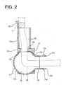
- FIGS. 1 to 5 show a first embodiment of the present invention, and a cable supporting device 10 (hereinafter, referred to as a "supporting device 10") is for supporting a cable 20 arranged to span between an automotive vehicle body (not shown) and a slide door (not shown) slidably connected to the vehicle body by allowing the cable to be inserted therethrough.
- a cable supporting device 10 hereinafter, referred to as a "supporting device 10”
- a cable supporting device 10 is for supporting a cable 20 arranged to span between an automotive vehicle body (not shown) and a slide door (not shown) slidably connected to the vehicle body by allowing the cable to be inserted therethrough.
- the supporting device 10 includes a spherical guide member 11 made of resin and a pair of first and second supporting members 12, 13 rotatably holding the spherical guide member 11 therebetween.
- the spherical guide member 11 has a spherical frame body 11a, a first opening 11 b communicating with a spherical hollow portion S1 of the frame body 11 a is formed in one side surface of the frame body 11a, and a second opening 11c communicating with the hollow portion S1 is formed in the upper side spaced apart by 90° from the first opening 11b.
- the first opening 11b is a rectangular opening, and a pair of connecting pieces 11d project from the opposite upper and lower edges of the first opening 11b and include pin-shaped projections 11e.
- the cable 20 is covered by a chained link member 22 in which a multitude of link members are successively rotatably connected.
- the pair of connecting pieces 11d are placed on and rotatably connected with a leading-end link member 21A of this chained link member 22.
- the chained link member 22 is so connected with the spherical guide member 11 as to be able to change its angle in transverse direction (swingable in transverse direction).
- the first supporting member 12 for tightly holding the spherical guide member 11 at one side includes a supporting portion 12a in the form of a thick plate for supporting the spherical guide member 11 and vehicle-body fixing portions 12b in the form of thin plates projecting sideways from the opposite left and right sides of the supporting portion 12a, and a fitting recess 12f to be fitted to the second supporting member 13 is formed in the inner surface of the supporting portion 12a.
- a spherical opening 12c is formed in the center of the supporting portion 12a, and the inner circumferential surface of the spherical opening 12c is formed into a curved surface in conformity with the outer circumferential surface of the spherical guide member 11.
- a plurality of grooves 12g extending from one end to the other end of the supporting member 12a in thickness direction and adapted to discharge foreign matters are formed in the inner circumferential surface of the spherical opening 12c while being circumferentially spaced apart.
- Four locking holes 12d used for the connection with the second supporting member 13 are formed around the spherical opening 12c while being circumferential spaced apart.
- bolt holes 12e are formed in the vehicle-body fixing portions 12b of the first supporting member 12.
- the second supporting member 13 for tightly holding the spherical guide member 11 at the other side includes a supporting portion 13a in the form of a thick plate for supporting the spherical guide member 11, vehicle-body fixing portions 13b in the form of thin plates projecting sideways from the opposite left and right sides of the supporting portion 13a, and a tubular portion 13c projecting upward from the upper side of the supporting portion 13a.
- a spherical opening 13d is formed in the center of the supporting portion 13a, and the inner circumferential surface of the spherical opening 13d is formed into a curved surface in conformity with the outer circumferential surface of the spherical guide member 11.
- a plurality of grooves 13i extending from one end to the other end of the supporting member 13a in thickness direction and adapted to discharge foreign matters are formed in the inner circumferential surface of the spherical opening 13d while being circumferentially spaced apart.
- a projection 13h having an arcuately curved surface in conformity with the outer circumferential surface of the spherical guide member 11 projects from the peripheral edge of the spherical opening 13d. This projection 13h is fitted into the fitting recess 12f of the first supporting member.
- the vehicle-body fixing portions 13b are held in contact with the vehicle-body fixing portions 12b of the first supporting member 12 and bolt holes 13g formed in the vehicle-body fixing portions 13b communicate with the bolt holes 12e of the vehicle-body fixing portions 12b.
- four locking pieces 13e to be inserted into the locking holes 12d of the first supporting member 12 for locking engagement are formed on the supporting portion 13b of the second supporting member 13 while being circumferential spaced apart.
- the bottom end of a hollow portion S2 of the tubular portion 13c projecting upward from the supporting portion 13a communicates with the spherical opening 13d, and a fixing piece 13f, to which the cable 20 inserted through the hollow portion S2 is fixed by taping, projects from the upper end of the tubular portion 13c.
- the grooves 12g formed in the inner circumferential surface of the spherical opening 12c of the first supporting member 12 and the grooves 13i formed in the inner circumferential surface of the spherical opening 13d of the second supporting member communicate, so that dust, sand, water and the like having entered between the spherical guide member 11 and the spherical openings 12c, 13d can be discharged to the outside through the grooves 12g, 13i.
- the cable 20 as a bundle of a plurality of wires arranged between the slide door and the vehicle body is inserted through the supporting device 10 having the spherical guide member 11 and the first and second supporting members 12, 13 assembled as above.
- the cable 20 inserted into the hollow portion S1 of the spherical guide member 11 from the first opening 11b is bent at 90° and inserted into the hollow space S2 of the tubular portion 13c through the second opening 11c, and the cable 20 pulled out from the upper end of the tubular portion 13c is fixed to the fixing piece 13f by winding a tape T.
- the supporting device 10 is fixed to a vehicle body panel by inserting unillustrated bolts (fastening members) through the communicating bolt holes 12e, 13g.
- the cable 20 pulled out from the tubular portion 13c of the second supporting member 13 of the supporting device 10 is arranged in the vehicle body to be connected with a floor harness (not shown) by means of a connector, whereas the cable 20 inserted into the first opening 11b of the spherical guide member 11 is arranged to span between the vehicle body and the slide door and connected with a door harness (not shown) by means of a connector. In this way, the floor harness and the door harness are electrically connected via the cable 20.
- the cable 20 inserted into the first opening 11b is covered by the chained link member 22 in which a plurality of link members 21 are connected.
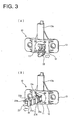
- the link members 21 have a rectangular tubular shape. As shown in FIG. 3(B) , a round through hole 21a is formed at the front or rear side of each of the upper and lower walls opposed to each other, and a pin-shaped projection 21b is provided on the opposite side thereof.
- a plurality of link members are so connected with each other as to be rotatable in transverse direction by fitting the pin-shaped projections 21b of one link member 21 into the through holes 21a of the adjacent link member 21.
- the through holes 21a of the leading-end link member 21A of the chained link member 22 covering the cable 20 are engaged with the pin-shaped projections 11e of the connecting pieces 11d of the spherical guide member 11 to rotatably connect the leading-end link member 21A.
- the chained link member 22 can be bent in transverse direction.
- link members and the leading-end link member and the spherical guide member 11 may be rotatably connected using separate pins.
- the cable 20 spanning between the vehicle body and the slide door is covered by the chained link member 22, inserted into the first opening 11b of the spherical guide member 11 connected with the leading-end link member of the chained link member at the vehicle body side, brought to the second opening 11c after passing the hollow portion S1 and pulled out through the hollow portion S2 of the tubular portion 13c from the second opening 11c.
- the chained link member 22 is bendable only in transverse direction, but the spherical guide member 11 is rotatably supported by the first and second supporting members 12, 13 so as to be rotatable in vertical, transverse and oblique directions.
- the spherical guide member 11 rotates to follow this angular change, wherefore the angle of the cable 20 smoothly changes.
- the spherical guide member 11 rotates in transverse direction in the first and second supporting members 12, 13 as shown in FIGS. 3 , whereby the angle changes in transverse direction over a wider range as compared to the transverse angular displacement only by the chained link member 22 to follow the angular change of the cable 20 in transverse direction.
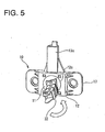
- the spherical guide member 11 rotates in circumferential direction in the first and second supporting members 12, 13 with respect to the spherical opening 12c as shown in FIG. 5 , whereby the angle of the chained link member 22 changes to follow the angular displacement of the cable 20 in an oblique direction.
- the angular changes of the cable in vertical, transverse and oblique directions can be followed by the rotation of the spherical guide member 11 and the amount of displacement of the cable is large. Therefore, this supporting device 10 can be used for other types of vehicles.
- the leading-end link member can have the same shape as the other link members, wherefore the number of parts can be reduced and the leading-end link member and the supporting member can be easily connected.
- the supporting device 10 is fixed to the vehicle body in this embodiment, it may be provided on the slide door depending on the vehicle type or may be provided on both the vehicle body and the slide door. If the supporting device 10 is provided on both the vehicle body and the slide door, the movable range of the cable can be widened.
- FIG. 6 shows a second embodiment of the present invention.
- the covering member covering the cable drawn out from the spherical guide member 11 of the supporting device 10 differs from that of the first embodiment.
- a corrugate tube 30, in which projected portions and recessed portions are alternately arranged in longitudinal direction, is mounted instead of the chained link member, and an end of the corrugate tube 30 toward the spherical guide member 11 is fitted and fixed in the first opening 11b of the spherical guide member 11.
- the corrugate tube 30 has an oblong cross-sectional shape along a direction normal to the longitudinal direction thereof, wherein the major axis direction of the corrugate tube 30 is a vertical direction and the minor axis direction thereof is a horizontal direction.
- ribs 31 extending in longitudinal direction are provided at the opposite upper and lower ends of the outer circumferential surface of the corrugate tube 30, thereby making the corrugate tube 30 difficult to vertically bend and easy to transversely bend for the restriction of the bending direction.
- the cross-sectional shape of the corrugate tube along the direction normal to longitudinal direction is not limited to the oblong shape, and may be an elliptical shape or a rectangular shape. If the bending direction can be restricted by the cross-sectional shape of the corrugate tube, it is not necessary to provide the ribs on the outer circumferential surface.
- the cable is not shown in FIG. 6 .
- the bending direction of the corrugate tube 30 is restricted to transverse direction, wherefore the cable can be bent in vertical direction and oblique direction by the rotation of the spherical guide member 11 while being prevented from hanging down.
Landscapes
- Engineering & Computer Science (AREA)
- Mechanical Engineering (AREA)
- Electric Cable Arrangement Between Relatively Moving Parts (AREA)
Claims (7)
- Kabelstütz- bzw. -trägervorrichtung zum Stützen bzw. Tragen eines Kabels (20), das zwischen einem Fahrzeugaufbau und einem beweglichen Glied angeordnet ist, das beweglich mit dem Fahrzeugaufbau verbunden ist, umfassend:ein Führungsglied (11), das eine erste Öffnung (11 b), die in einer Seitenfläche bzw. -oberfläche eines Rahmenkörpers (11a) gebildet ist, mit einem hohlen Abschnitt des Rahmenkörpers (11a) kommuniziert und zum Einsetzen des Kabels (20) verwendet wird, und eine zweite Öffnung (11c) enthält, die in einer oberen oder unteren Seite des Rahmenkörpers (11 a) gebildet ist, mit dem hohlen Abschnitt kommuniziert und zum Einsetzen des Kabels (20) verwendet wird,gekennzeichnet durcheine dreidimensionale bogenförmige Fläche bzw. Oberfläche an der äußeren Fläche bzw. Oberfläche des Rahmenkörpers (11a), undein Stütz- bzw. Trägerglied (12) zum drehbaren festen Halten der bogenförmigen Fläche bzw. Oberfläche des Führungsglieds (11), wobei das Stütz- bzw. Trägerglied (12) an dem Fahrzeugaufbau und/oder beweglichen Glied fixiert bzw. befestigt ist,wobei das Kabel (20) von der ersten Öffnung (11 b) des Führungsglieds (11) zu der zweiten Öffnung (11c) durch den hohlen Abschnitt eingesetzt wird, so dass das Führungsglied (11) Winkeländerungen des Kabels (20) in vertikaler Richtung, Querrichtung und schräger Richtung folgen kann.
- Kabelträgervorrichtung nach Anspruch 1, wobei:die erste Öffnung (11 b) und die zweite Öffnung (11 c) des Führungsglieds (11) sich an orthogonalen Positionen befinden, unddas Führungsende eines Abdeckungsglieds, das ein verkettetes Glied bzw. Kettenglied (21) oder gewelltes Rohr bzw. Wellrohr (30) ist, welches das Kabel (20) abdeckt, mit der ersten Öffnung (11 b) verbunden ist, um innerhalb eines spezifizierten Winkelbereichs drehbar zu sein, wohingegen das Kabel (20), das sich von dem Führungsende des Abdeckungsglieds erstreckt, durch den hohlen Abschnitt des Führungsglieds (11) von bzw. aus der ersten Öffnung (11) geführt ist und aus der zweiten Öffnung (11c) herausgezogen ist, um an dem Trägerglied (12) fixiert bzw. befestigt zu sein.
- Kabelträgervorrichtung nach Anspruch 1, wobei:das Führungsglied (11) ein sphärisches Führungsglied ist, das einen sphärischen Rahmenkörper (11 a) enthält, und das Trägerglied (12) ein erstes Trägerglied (12) und ein zweites Trägerglied (13) enthält, mit Öffnungen zum drehbaren Stützen bzw. Tragen der Außenumfangsfläche bzw. -oberfläche des sphärischen Führungsglieds an den gegenüberliegenden bzw. entgegengesetzten Seiten im Inneren bzw. auf der Innenseite,die erste Öffnung (11 b) des sphärischen Führungsglieds in einer Seitenfläche bzw. -oberfläche gebildet ist und ein Paar Verbindungsstücke von den gegenüberliegenden bzw. entgegengesetzten oberen und unteren Kanten bzw. Rändern der ersten Öffnung (11 b) vorspringt, veranlasst wird, aus einer sphärischen Öffnung des ersten Trägerglieds (12) vorzuspringen und drehbar mit einem Führungsendbindeglied des Kettenglieds (21) verbunden sind, welches das Kabel (20) abdeckt, so dass das Führungsendbindeglied drehbar in Querrichtung verbunden ist und die angrenzenden bzw. benachbarten Bindeglieder des Kettenglieds (21), die sukzessive bzw. nacheinander mit dem Führungsendbindeglied verbunden sind, ebenfalls drehbar in Querrichtung verbunden sind,wohingegen die zweite Öffnung (11c) des sphärischen Führungsglieds an einer oberen Seite beabstandet um ca. 90° von der ersten Öffnung (11 b) gebildet ist und das Kabel (20), das von bzw. aus der ersten Öffnung (11 b) eingesetzt ist, ist aus der zweiten Öffnung (11 c) herausgezogen nachdem es um ca. 90° in dem hohlen Abschnitt des sphärischen Führungsglieds gebogen ist, so dass sich das sphärische Führungsglied in vertikaler Richtung, Querrichtung und schräger Richtung dreht, um der Winkeländerung des Kabels (20) in vertikaler Richtung, Querrichtung und schräger Richtung zu folgen.
- Kabelträgervorrichtung nach Anspruch 3, wobei das Kabel (20) an dem zweiten Trägerglied (13) fixiert bzw. befestigt ist durch Bereitstellen bzw. Versehen des zweiten Trägerglieds (13) mit einem rohrförmigen Abschnitt, der mit der zweiten Öffnung (11c) des sphärischen Führungsglieds kommuniziert und nach oben vorspringt, und Bereitstellen eines Fixier- bzw. Befestigungsstücks (13f) für das Kabel (20), das von dem oberen Ende des rohrförmigen Abschnitts vorspringt.
- Kabelträgervorrichtung nach Anspruch 3 oder 4, wobei:eine Mehrzahl von Verriegelungsstücken (13e) von der Umfangskante bzw. -rand der sphärischen Öffnung von einem des ersten und des zweiten Trägerglieds (12, 13) vorspringt, während sie umfangsmäßig voneinander beabstandet sind, wohingegen Verriegelungslöcher (12d), die mit den Verriegelungsstücken (13e) in Eingriff bringbar sind, in dem anderen des ersten und des zweiten Trägerglieds (12, 13) gebildet sind, unddas erste und das zweite Trägerglied (12, 13) mit dem sphärischen Führungsglied verbunden sind, das von den Verriegelungsstücken (13e) umgeben und gehalten ist.
- Kabelträgervorrichtung nach einem der Ansprüche 1 bis 5, wobei eine Stütz- bzw. Trägerfläche des Trägerglieds (12) zum drehbaren Stützen bzw. Tragen der bogenförmigen Fläche des Führungsglieds (11) mit Nuten bzw. Rillen zum Ausstoßen von Fremdstoffen gebildet ist.
- Kabelträgervorrichtung nach einem der Ansprüche 1 bis 6, wobei:das Kabel (20) zwischen dem Fahrzeugaufbau und einer Schiebetür angeordnet ist,das Trägerglied (12) zum drehbaren festen Halten des Führungsglieds (11) an dem Fahrzeugaufbau und/oder der Schiebetür fixiert bzw. befestigt ist, undsich das Führungsglied (11) dreht, um der Winkeländerung des Kabels (20) zu folgen, wenn die Schiebetür geöffnet oder geschlossen ist bzw. wird.
Applications Claiming Priority (2)
| Application Number | Priority Date | Filing Date | Title |
|---|---|---|---|
| JP2005300613A JP4442545B2 (ja) | 2005-10-14 | 2005-10-14 | ケーブルの支持装置 |
| PCT/JP2006/313737 WO2007043225A1 (ja) | 2005-10-14 | 2006-07-11 | ケーブルの支持装置 |
Publications (3)
| Publication Number | Publication Date |
|---|---|
| EP1936767A1 EP1936767A1 (de) | 2008-06-25 |
| EP1936767A4 EP1936767A4 (de) | 2010-07-28 |
| EP1936767B1 true EP1936767B1 (de) | 2014-08-20 |
Family
ID=37942487
Family Applications (1)
| Application Number | Title | Priority Date | Filing Date |
|---|---|---|---|
| EP06780958.2A Not-in-force EP1936767B1 (de) | 2005-10-14 | 2006-07-11 | Einrichtung zur kabelunterstützung |
Country Status (5)
| Country | Link |
|---|---|
| US (1) | US7861508B2 (de) |
| EP (1) | EP1936767B1 (de) |
| JP (1) | JP4442545B2 (de) |
| CN (1) | CN101288214B (de) |
| WO (1) | WO2007043225A1 (de) |
Cited By (1)
| Publication number | Priority date | Publication date | Assignee | Title |
|---|---|---|---|---|
| EP4104266B1 (de) * | 2020-02-16 | 2024-07-24 | Newfrey LLC | Kabelführung und kraftfahrzeug |
Families Citing this family (24)
| Publication number | Priority date | Publication date | Assignee | Title |
|---|---|---|---|---|
| JP5012063B2 (ja) * | 2007-02-05 | 2012-08-29 | 住友電装株式会社 | 自動車用ワイヤハーネスの配索構造 |
| JP4442622B2 (ja) * | 2007-03-13 | 2010-03-31 | 三菱自動車工業株式会社 | 電気自動車用ケーブル接続構造 |
| JP5040434B2 (ja) * | 2007-05-16 | 2012-10-03 | 住友電装株式会社 | スライドドア用ハーネスの配索構造 |
| JP5091061B2 (ja) * | 2008-09-02 | 2012-12-05 | 矢崎総業株式会社 | スライドドア部の給電構造 |
| CN101994896A (zh) * | 2009-08-17 | 2011-03-30 | 鸿富锦精密工业(深圳)有限公司 | 连接装置 |
| JP5434556B2 (ja) * | 2009-12-16 | 2014-03-05 | 住友電装株式会社 | ワイヤーハーネス支持具及び導電経路装置 |
| JP5929029B2 (ja) * | 2011-08-04 | 2016-06-01 | 住友電装株式会社 | ワイヤーハーネス配索装置 |
| US8753030B2 (en) * | 2012-03-01 | 2014-06-17 | U.S.T.E., Inc. | Mounting knuckle |
| JP6029138B2 (ja) * | 2013-01-22 | 2016-11-24 | 矢崎総業株式会社 | 給電装置 |
| JP6146909B2 (ja) * | 2013-10-11 | 2017-06-14 | 矢崎総業株式会社 | 給電装置及び給電装置の組立方法 |
| JP6211375B2 (ja) * | 2013-10-11 | 2017-10-11 | 矢崎総業株式会社 | 給電装置 |
| JP6161033B2 (ja) | 2013-10-11 | 2017-07-12 | 矢崎総業株式会社 | 給電装置 |
| KR101667559B1 (ko) * | 2015-04-23 | 2016-10-19 | 주식회사 성우하이텍 | 브레이크 케이블 가이드 유닛 |
| US9956928B2 (en) * | 2015-06-30 | 2018-05-01 | Fca Us Llc | Track assembly for sliding vehicle door |
| JP6488981B2 (ja) * | 2015-10-13 | 2019-03-27 | 住友電装株式会社 | 電線配索装置 |
| CN105762751B (zh) * | 2016-04-29 | 2017-10-13 | 山东博特精工股份有限公司 | 淬火机床变压器移动淬火电缆的安装装置 |
| JP6644240B2 (ja) * | 2016-12-06 | 2020-02-12 | トヨタ車体株式会社 | ワイヤハーネスの支持具 |
| CN107508161A (zh) * | 2017-09-04 | 2017-12-22 | 浙江麦浪电气股份有限公司 | 一种便于安装布线的高低压柜 |
| US11904781B2 (en) * | 2019-03-27 | 2024-02-20 | Sumitomo Wiring Systems, Limited | Wire harness with body protrusion |
| CN111071088B (zh) * | 2019-12-30 | 2023-08-15 | 无锡道驰光电科技有限公司 | 一种电动车自动充电方法和装置 |
| CN111114359B (zh) * | 2019-12-30 | 2023-08-22 | 无锡道驰光电科技有限公司 | 用于充电桩和充电机器人的充电线缆跟随方法和机构 |
| US11464131B2 (en) * | 2020-02-07 | 2022-10-04 | Seagate Technology Llc | Cable management assembly |
| JP7078659B2 (ja) * | 2020-03-03 | 2022-05-31 | 矢崎総業株式会社 | 本体側ユニットおよびワイヤハーネスの配索構造 |
| CN111577493B (zh) * | 2020-05-15 | 2022-02-15 | 浙江博弈科技股份有限公司 | 一种带万向线束卡扣的进气歧管 |
Family Cites Families (12)
| Publication number | Priority date | Publication date | Assignee | Title |
|---|---|---|---|---|
| US3215405A (en) * | 1962-11-06 | 1965-11-02 | Breeze Corp | Fleet angle control device |
| JP2000291626A (ja) * | 1999-04-08 | 2000-10-20 | Minebea Co Ltd | ケーブル案内用ボールジョイント |
| JP3467465B2 (ja) | 2000-09-27 | 2003-11-17 | 矢崎総業株式会社 | ワイヤーハーネス巻取り装置の異物排出構造 |
| JP3743279B2 (ja) | 2000-10-30 | 2006-02-08 | 日産自動車株式会社 | スライドドアのドアハーネス配索構造 |
| JP3836758B2 (ja) | 2002-07-01 | 2006-10-25 | 本田技研工業株式会社 | ケーブル支持部構造 |
| JP4261947B2 (ja) | 2003-03-14 | 2009-05-13 | 矢崎総業株式会社 | スライドドア給電用のハーネス固定具とそれを用いた給電構造 |
| JP2005000810A (ja) | 2003-06-12 | 2005-01-06 | Hiroe Tsunoda | 生物廃棄物処理法、生物廃棄物処理法による生成物、生成物加工品 |
| JP4102714B2 (ja) * | 2003-06-18 | 2008-06-18 | 矢崎総業株式会社 | スライドドア給電用のハーネス保護構造 |
| JP2005148932A (ja) * | 2003-11-12 | 2005-06-09 | Toshiba Corp | 支持装置 |
| JP2006327328A (ja) * | 2005-05-24 | 2006-12-07 | Honda Motor Co Ltd | ハーネスの配索構造 |
| US7302907B2 (en) * | 2005-07-25 | 2007-12-04 | Correct Craft, Inc. | Mounting system and method for rigidly attaching a water sports towing frame to a vessel |
| JP4235205B2 (ja) * | 2006-01-11 | 2009-03-11 | 矢崎総業株式会社 | ハーネス外装部材とそれを用いたハーネス配索構造 |
-
2005
- 2005-10-14 JP JP2005300613A patent/JP4442545B2/ja active Active
-
2006
- 2006-07-11 US US12/083,316 patent/US7861508B2/en active Active
- 2006-07-11 CN CN2006800381420A patent/CN101288214B/zh active Active
- 2006-07-11 EP EP06780958.2A patent/EP1936767B1/de not_active Not-in-force
- 2006-07-11 WO PCT/JP2006/313737 patent/WO2007043225A1/ja active Application Filing
Cited By (1)
| Publication number | Priority date | Publication date | Assignee | Title |
|---|---|---|---|---|
| EP4104266B1 (de) * | 2020-02-16 | 2024-07-24 | Newfrey LLC | Kabelführung und kraftfahrzeug |
Also Published As
| Publication number | Publication date |
|---|---|
| US7861508B2 (en) | 2011-01-04 |
| WO2007043225A1 (ja) | 2007-04-19 |
| JP2007110851A (ja) | 2007-04-26 |
| EP1936767A4 (de) | 2010-07-28 |
| CN101288214B (zh) | 2010-09-29 |
| JP4442545B2 (ja) | 2010-03-31 |
| US20090121093A1 (en) | 2009-05-14 |
| EP1936767A1 (de) | 2008-06-25 |
| CN101288214A (zh) | 2008-10-15 |
Similar Documents
| Publication | Publication Date | Title |
|---|---|---|
| EP1936767B1 (de) | Einrichtung zur kabelunterstützung | |
| EP1944198B1 (de) | Kabelstützvorrichtung | |
| US9150168B2 (en) | Sliding door wire harness routing structure | |
| US8070212B2 (en) | Arranging structure of wire harness for motor vehicle | |
| EP1241054B1 (de) | Kabelbaumanordnung für eine Kraftfahrzeugschiebetür | |
| EP1731373B1 (de) | Kabelbaum-Haltevorrichtung | |
| US20070158092A1 (en) | Harness wire cover and harness wiring structure having the same | |
| US7381898B2 (en) | Electrical connection structure | |
| JP3831198B2 (ja) | スライドドアへのハーネス配索構造 | |
| WO2007029705A1 (ja) | スライドドア用給電装置 | |
| US9178302B2 (en) | Wire cover, wiring method of wires and electrical connector | |
| EP2045139B1 (de) | Kabelbaumschutzstruktur für Verbindungsstück | |
| CN112238825A (zh) | 滑动门线束 | |
| US6809264B2 (en) | Feeder assembly of car sliding door | |
| JP2007159372A (ja) | ケーブルのガイド装置 | |
| JP2007159369A (ja) | ケーブルのガイド装置 | |
| WO2020174831A1 (ja) | ワイヤハーネス用プロテクタおよびワイヤハーネス装置 | |
| JP4893332B2 (ja) | ワイヤハーネスの配索支持装置 | |
| JP2007181333A (ja) | スライド構造体用の給電装置 | |
| CN113453957B (zh) | 电缆导向件及线束装置 | |
| WO2023112556A1 (ja) | プロテクタ | |
| EP4016775B1 (de) | Verbinder für vorrichtung | |
| WO2022172705A1 (ja) | スライドドア給電装置 | |
| JP2024133785A (ja) | プロテクタおよびワイヤハーネス | |
| JP2004248431A (ja) | スライドドアの給電構造 |
Legal Events
| Date | Code | Title | Description |
|---|---|---|---|
| PUAI | Public reference made under article 153(3) epc to a published international application that has entered the european phase |
Free format text: ORIGINAL CODE: 0009012 |
|
| 17P | Request for examination filed |
Effective date: 20080417 |
|
| AK | Designated contracting states |
Kind code of ref document: A1 Designated state(s): DE FR |
|
| DAX | Request for extension of the european patent (deleted) | ||
| RBV | Designated contracting states (corrected) |
Designated state(s): DE FR |
|
| A4 | Supplementary search report drawn up and despatched |
Effective date: 20100624 |
|
| RIN1 | Information on inventor provided before grant (corrected) |
Inventor name: KOBAYASHI, YOSHINAO Inventor name: MURAYAMA, SHIGEKI |
|
| GRAP | Despatch of communication of intention to grant a patent |
Free format text: ORIGINAL CODE: EPIDOSNIGR1 |
|
| INTG | Intention to grant announced |
Effective date: 20140227 |
|
| GRAS | Grant fee paid |
Free format text: ORIGINAL CODE: EPIDOSNIGR3 |
|
| GRAA | (expected) grant |
Free format text: ORIGINAL CODE: 0009210 |
|
| AK | Designated contracting states |
Kind code of ref document: B1 Designated state(s): DE FR |
|
| REG | Reference to a national code |
Ref country code: DE Ref legal event code: R096 Ref document number: 602006042770 Country of ref document: DE Effective date: 20141002 |
|
| REG | Reference to a national code |
Ref country code: DE Ref legal event code: R097 Ref document number: 602006042770 Country of ref document: DE |
|
| PLBE | No opposition filed within time limit |
Free format text: ORIGINAL CODE: 0009261 |
|
| STAA | Information on the status of an ep patent application or granted ep patent |
Free format text: STATUS: NO OPPOSITION FILED WITHIN TIME LIMIT |
|
| 26N | No opposition filed |
Effective date: 20150521 |
|
| REG | Reference to a national code |
Ref country code: FR Ref legal event code: PLFP Year of fee payment: 11 |
|
| PGFP | Annual fee paid to national office [announced via postgrant information from national office to epo] |
Ref country code: FR Payment date: 20160613 Year of fee payment: 11 |
|
| PGFP | Annual fee paid to national office [announced via postgrant information from national office to epo] |
Ref country code: DE Payment date: 20160705 Year of fee payment: 11 |
|
| REG | Reference to a national code |
Ref country code: DE Ref legal event code: R119 Ref document number: 602006042770 Country of ref document: DE |
|
| REG | Reference to a national code |
Ref country code: FR Ref legal event code: ST Effective date: 20180330 |
|
| PG25 | Lapsed in a contracting state [announced via postgrant information from national office to epo] |
Ref country code: DE Free format text: LAPSE BECAUSE OF NON-PAYMENT OF DUE FEES Effective date: 20180201 |
|
| PG25 | Lapsed in a contracting state [announced via postgrant information from national office to epo] |
Ref country code: FR Free format text: LAPSE BECAUSE OF NON-PAYMENT OF DUE FEES Effective date: 20170731 |