EP1933010B1 - Motorrad - Google Patents
Motorrad Download PDFInfo
- Publication number
- EP1933010B1 EP1933010B1 EP07023188A EP07023188A EP1933010B1 EP 1933010 B1 EP1933010 B1 EP 1933010B1 EP 07023188 A EP07023188 A EP 07023188A EP 07023188 A EP07023188 A EP 07023188A EP 1933010 B1 EP1933010 B1 EP 1933010B1
- Authority
- EP
- European Patent Office
- Prior art keywords
- conduit
- secondary air
- inducting
- engine
- disposed
- Prior art date
- Legal status (The legal status is an assumption and is not a legal conclusion. Google has not performed a legal analysis and makes no representation as to the accuracy of the status listed.)
- Not-in-force
Links
Images




Classifications
-
- F—MECHANICAL ENGINEERING; LIGHTING; HEATING; WEAPONS; BLASTING
- F01—MACHINES OR ENGINES IN GENERAL; ENGINE PLANTS IN GENERAL; STEAM ENGINES
- F01N—GAS-FLOW SILENCERS OR EXHAUST APPARATUS FOR MACHINES OR ENGINES IN GENERAL; GAS-FLOW SILENCERS OR EXHAUST APPARATUS FOR INTERNAL-COMBUSTION ENGINES
- F01N3/00—Exhaust or silencing apparatus having means for purifying, rendering innocuous, or otherwise treating exhaust
- F01N3/08—Exhaust or silencing apparatus having means for purifying, rendering innocuous, or otherwise treating exhaust for rendering innocuous
- F01N3/10—Exhaust or silencing apparatus having means for purifying, rendering innocuous, or otherwise treating exhaust for rendering innocuous by thermal or catalytic conversion of noxious components of exhaust
- F01N3/24—Exhaust or silencing apparatus having means for purifying, rendering innocuous, or otherwise treating exhaust for rendering innocuous by thermal or catalytic conversion of noxious components of exhaust characterised by constructional aspects of converting apparatus
- F01N3/30—Arrangements for supply of additional air
- F01N3/34—Arrangements for supply of additional air using air conduits or jet air pumps, e.g. near the engine exhaust port
-
- F—MECHANICAL ENGINEERING; LIGHTING; HEATING; WEAPONS; BLASTING
- F01—MACHINES OR ENGINES IN GENERAL; ENGINE PLANTS IN GENERAL; STEAM ENGINES
- F01N—GAS-FLOW SILENCERS OR EXHAUST APPARATUS FOR MACHINES OR ENGINES IN GENERAL; GAS-FLOW SILENCERS OR EXHAUST APPARATUS FOR INTERNAL-COMBUSTION ENGINES
- F01N13/00—Exhaust or silencing apparatus characterised by constructional features
- F01N13/009—Exhaust or silencing apparatus characterised by constructional features having two or more separate purifying devices arranged in series
-
- F—MECHANICAL ENGINEERING; LIGHTING; HEATING; WEAPONS; BLASTING
- F01—MACHINES OR ENGINES IN GENERAL; ENGINE PLANTS IN GENERAL; STEAM ENGINES
- F01N—GAS-FLOW SILENCERS OR EXHAUST APPARATUS FOR MACHINES OR ENGINES IN GENERAL; GAS-FLOW SILENCERS OR EXHAUST APPARATUS FOR INTERNAL-COMBUSTION ENGINES
- F01N3/00—Exhaust or silencing apparatus having means for purifying, rendering innocuous, or otherwise treating exhaust
- F01N3/08—Exhaust or silencing apparatus having means for purifying, rendering innocuous, or otherwise treating exhaust for rendering innocuous
- F01N3/10—Exhaust or silencing apparatus having means for purifying, rendering innocuous, or otherwise treating exhaust for rendering innocuous by thermal or catalytic conversion of noxious components of exhaust
-
- B—PERFORMING OPERATIONS; TRANSPORTING
- B62—LAND VEHICLES FOR TRAVELLING OTHERWISE THAN ON RAILS
- B62J—CYCLE SADDLES OR SEATS; AUXILIARY DEVICES OR ACCESSORIES SPECIALLY ADAPTED TO CYCLES AND NOT OTHERWISE PROVIDED FOR, e.g. ARTICLE CARRIERS OR CYCLE PROTECTORS
- B62J17/00—Weather guards for riders; Fairings or stream-lining parts not otherwise provided for
- B62J17/02—Weather guards for riders; Fairings or stream-lining parts not otherwise provided for shielding only the rider's front
-
- F—MECHANICAL ENGINEERING; LIGHTING; HEATING; WEAPONS; BLASTING
- F01—MACHINES OR ENGINES IN GENERAL; ENGINE PLANTS IN GENERAL; STEAM ENGINES
- F01N—GAS-FLOW SILENCERS OR EXHAUST APPARATUS FOR MACHINES OR ENGINES IN GENERAL; GAS-FLOW SILENCERS OR EXHAUST APPARATUS FOR INTERNAL-COMBUSTION ENGINES
- F01N2230/00—Combination of silencers and other devices
- F01N2230/04—Catalytic converters
-
- F—MECHANICAL ENGINEERING; LIGHTING; HEATING; WEAPONS; BLASTING
- F01—MACHINES OR ENGINES IN GENERAL; ENGINE PLANTS IN GENERAL; STEAM ENGINES
- F01N—GAS-FLOW SILENCERS OR EXHAUST APPARATUS FOR MACHINES OR ENGINES IN GENERAL; GAS-FLOW SILENCERS OR EXHAUST APPARATUS FOR INTERNAL-COMBUSTION ENGINES
- F01N2340/00—Dimensional characteristics of the exhaust system, e.g. length, diameter or volume of the exhaust apparatus; Spatial arrangements of exhaust apparatuses
- F01N2340/04—Arrangement of the exhaust system relative to a vehicle or parts thereof
-
- F—MECHANICAL ENGINEERING; LIGHTING; HEATING; WEAPONS; BLASTING
- F01—MACHINES OR ENGINES IN GENERAL; ENGINE PLANTS IN GENERAL; STEAM ENGINES
- F01N—GAS-FLOW SILENCERS OR EXHAUST APPARATUS FOR MACHINES OR ENGINES IN GENERAL; GAS-FLOW SILENCERS OR EXHAUST APPARATUS FOR INTERNAL-COMBUSTION ENGINES
- F01N2590/00—Exhaust or silencing apparatus adapted to particular use, e.g. for military applications, airplanes, submarines
- F01N2590/04—Exhaust or silencing apparatus adapted to particular use, e.g. for military applications, airplanes, submarines for motorcycles
-
- Y—GENERAL TAGGING OF NEW TECHNOLOGICAL DEVELOPMENTS; GENERAL TAGGING OF CROSS-SECTIONAL TECHNOLOGIES SPANNING OVER SEVERAL SECTIONS OF THE IPC; TECHNICAL SUBJECTS COVERED BY FORMER USPC CROSS-REFERENCE ART COLLECTIONS [XRACs] AND DIGESTS
- Y02—TECHNOLOGIES OR APPLICATIONS FOR MITIGATION OR ADAPTATION AGAINST CLIMATE CHANGE
- Y02A—TECHNOLOGIES FOR ADAPTATION TO CLIMATE CHANGE
- Y02A50/00—TECHNOLOGIES FOR ADAPTATION TO CLIMATE CHANGE in human health protection, e.g. against extreme weather
- Y02A50/20—Air quality improvement or preservation, e.g. vehicle emission control or emission reduction by using catalytic converters
-
- Y—GENERAL TAGGING OF NEW TECHNOLOGICAL DEVELOPMENTS; GENERAL TAGGING OF CROSS-SECTIONAL TECHNOLOGIES SPANNING OVER SEVERAL SECTIONS OF THE IPC; TECHNICAL SUBJECTS COVERED BY FORMER USPC CROSS-REFERENCE ART COLLECTIONS [XRACs] AND DIGESTS
- Y02—TECHNOLOGIES OR APPLICATIONS FOR MITIGATION OR ADAPTATION AGAINST CLIMATE CHANGE
- Y02T—CLIMATE CHANGE MITIGATION TECHNOLOGIES RELATED TO TRANSPORTATION
- Y02T10/00—Road transport of goods or passengers
- Y02T10/10—Internal combustion engine [ICE] based vehicles
- Y02T10/12—Improving ICE efficiencies
Definitions
- the present invention relates to a straddle type vehicle, for example, a motorcycle.
- Prior art document EP 1 749 988 A1 discloses a straddle type vehicle comprising an engine disposed between front and rear wheels, and first and second catalytic converters disposed in an exhaust conduit of the engine, wherein a secondary air inducting conduit is provided for supplying secondary air to the exhaust conduit at a position between the first and second catalytic converters, and wherein a part of the secondary air inducting conduit is exposed at least either forward or sideward in the vehicle in the rear of the front wheel to form a secondary air cooling conduit.
- Prior art document US 5396767 discloses an engine exhaust gas cleaning system including a converter section that is disposed at the rear end of the exhaust pipe and which has an outer shell that is surrounded by a further outer shell having a rearwardly disposed atmospheric air inlet and a forwardly disposed atmospheric air outlet that communicates with the inlet of the converter through a venturi section. This heats the air admitted to the converter and also insures that any exhaust sound or exhaust leakage will be disposed rearwardly.
- a catalytic converter (catalyzer) is provided in a midway of an exhaust conduit, through which exhaust gas from the engine is emitted, and the purification is made by the catalyzer (for example, see Patent Document 1).
- Patent Document 1 JP-A-2001-130474
- the vehicle has a construction such that the secondary air inducting conduit extending downward from an air cleaner toward the exhaust conduit is covered from the front and the side by a vehicle cover and the like.
- the vehicle cover hinders heat at a high temperature from being emitted outside, and the heat at a high temperature is apt to directly transmit to the secondary air inducting conduit.
- a straddle type vehicle comprising an engine disposed between front and rear wheels, and first and second catalytic connectors disposed in an exhaust conduit of the engine, wherein a secondary air inducting conduit is provided for supplying secondary air to the exhaust conduit at a position between the first and second catalytic converters, and wherein a part of the secondary air inducting conduit is exposed at least either forward or sideward in the vehicle in the rear of the front wheel to form a secondary air cooling conduit.
- the first and second catalytic converters are a front catalytic converter and a rear catalytic converter spaced apart in the fore to aft direction in a midway part of an exhaust conduit of the engine, and wherein a downstream end of the secondary air inducting conduit is connected to the exhaust conduit in a position between the front catalytic converter and the rear catalytic converter.
- At least one conduit section of a secondary air inducting conduit is exposed to the space in the rear of a front wheel and in front of an engine to become the secondary air cooling conduit section for cooling down secondary air, to cool down secondary air flowing thought the secondary air inducting conduit, and to increase the oxygen concentration of secondary air.
- At least one conduit section is exposed to an inside of a space formed on a front part of the vehicle body and in the rear of the front wheel, and constructs the secondary air cooling conduit.
- At least one conduit section is disposed to be exposed to a space on a side of the vehicle body in the rear of the front wheel.
- the secondary air cooling conduit section is at least partially formed with a metal pipe.
- connection part of the secondary air inducting conduit which is connected to the exhaust conduit, is disposed below the engine, and the secondary air inducting conduit is formed to extend from the connection part in the horizontal direction below the engine.
- a part of the secondary air inducting conduit is formed to extend from either one of the right side and the left side to the other side traversing a center of the vehicle.
- a frame is formed with right and left frames, at least a part of the secondary air inducting conduit is disposed to overlap the right and left frames in a side view.
- a motorcycle 1 according to the embodiment of the present teaching includes a frame 10, an engine 20, an exhaust conduit 30, a front catalyzer 40, a rear catalyzer 50, and a secondary air inducting conduit 80.
- the frame 10 includes a head pipe 11, a left frame 12 formed with a generally parallelogram-shaped frame body, and a right frame 13 similarly formed with a generally parallelogram-shaped frame body (see FIGs. 2 and 3 ).
- the left frame 12 is connected to an upper end of the head pipe 11 at its front end.
- the left frame 12 includes a first frame part 12A extending rearward obliquely downward therefrom, a second frame part 12B extending rearward obliquely downward from a rear end of the first frame part 12A curving in a dog leg shape and curvedly extending forward obliquely downward at its lower end, a third frame part 12C curvedly extending forward from the lower end of the second frame part 12B in a generally horizontal direction, and a fourth frame part 12D curvedly extending forward obliquely upward from a front end of the third frame part 12C and connected to a lower end of the head pipe 11 at its upper end.
- the left frame 12 includes a seat rail 12E connected to a boundary part between the first frame part 12A and the second frame part 12B at its front end and extending rearward in a generally horizontal direction therefrom, and a backstay 12F connected to a middle part of the second frame part 12B in the direction of the length at its front end and extending rearward obliquely upward therefrom.
- the seat rail 12E is connected to a midway part (not shown) of the backstay 12F at its rear end.
- the right frame 13 similarly to the left frame 12, the right frame 13 includes a first frame part 13A, a second frame part 13B, a third frame part 13C, a fourth frame part 13D, a seat rail 13E, and a backstay 13F.
- a rotating shaft (not shown) provided on handlebars 14 is rotatably fitted into the head pipe 11.
- the rotating shaft of the handlebars 14 is fixed to a middle part of an upper bracket 15 in the direction of the length and a middle part of an under bracket 16 in the direction of the length.
- parts around upper ends of left and right front forks 17 are inserted and fixed to both left and right ends of those brackets 15 and 16.
- a front wheel 60 is rotatably coupled to lower ends of the front forks 17.
- Front ends of a swing arm 18 are swingably coupled to and supported by the second frame part 12B of the left frame 12 and the second frame part 13B of the right frame 13.
- a rear wheel 70 is rotatably coupled to rear ends of the swing arm 18.
- an air cleaner 19 is disposed in a position in the rear of the engine 20 between the seat rail 12 E and the backstay 12F of the frame 10.
- the air cleaner 19 removes debris such as dust contained in air supplied to the engine 20 and the secondary air inducting conduit 80.
- the engine 20 is disposed inside each of the left frame 12 and the right frame 13 formed with generally rectangular frame bodies (see FIG. 2 ), and is suspended by those frames 12 and 13. As shown in FIGs. 1 and 2 , the engine 20 includes a crankcase 21 and a cylinder 22 provided on an upper part of the crankcase 21.
- the exhaust conduit 30 includes a first pipe 31 extending forward from the cylinder 22 of the engine 20 curving in an arc shape, a second pipe 32 extending rearward obliquely downward from the first pipe 31, a third pipe 33 extending rearward from the second pipe 32 in a generally horizontal direction and connected to the front catalyzer 40, a fourth pipe 34 extending rearward from the front catalyzer 40 in a generally horizontal direction, a fifth pipe 35 curvedly extending rearward obliquely upward from the fourth pipe 34, and a muffler 36 connected to the fifth pipe 35.
- the exhaust conduit 30 discharges exhaust gas from the engine 20 outside via the front catalyzer 40, the rear catalyzer 50 and the muffler 36.
- the front catalyzer 40 is disposed in a position below the crankcase 21 between the third pipe 33 and the fourth pipe 34 of the exhaust conduit 30.
- the front catalyzer 40 is formed into a flat shape in which a width in the transverse direction is larger than a height in the vertical direction. Therefore, the front catalyzer 40 does not protrude more downward than the third pipe 33 and the fourth pipe 34 of the exhaust conduit 30 extending in the horizontal direction below the crankcase 21, and thereby a minimum height of the vehicle body from the ground is assured.
- the rear catalyzer 50 is disposed in the muffler 36 of the exhaust conduit 30 positioned downstream of the front catalyzer 40.
- the front catalyzer 40 and the rear catalyzer 50 facilitate combustion of deleterious elements (HC, NO x and so forth) included in exhaust gas discharged from the engine 20, and thereby purify the exhaust gas.
- the secondary air inducting conduit 80 inducts outside air passed through the air cleaner 19 into the rear catalyzer 50 via the fourth pipe 34 of the exhaust conduit 30, and enhances combustion efficiency of exhaust gas in the rear catalyzer 50.
- the secondary air inducting conduit 80 is formed with a metal pipe, rubber hose, or the like as shown in FIGs. 2 through 5 .
- the secondary air inducting conduit 80 is connected to a front end of the air cleaner 19 at its upstream end.
- the secondary air inducting conduit 80 includes a first conduit section 80A extending forward obliquely rightward therefrom, a second conduit section 80B extending from the first conduit section 80A gradually curving in an arc shape in a part above and the right of the cylinder 22, a third conduit section 80C extending from the second conduit section 80B, which is on one side (right side) in the right to left direction, to the other side in the right to left direction (left side) and traversing the center line L of the vehicle (see FIG. 4 ) in front of the cylinder 22, and a fourth conduit section 80D drooping from the third conduit section 80C.
- the secondary air inducting conduit 80 includes a fifth conduit section 80E extending rearward obliquely downward from the fourth conduit section 80D curving in a dog leg shape, a sixth conduit section 80F extending rearward from the fifth conduit section 80E in a generally horizontal direction curving in a L shape and partly overlapping the third frame 12C of the left frame 12 in a side view, and a seventh conduit section 80G (see FIG. 3 ) extending rightward from the sixth conduit section 80F in the horizontal direction curving in an arc shape, of which a downstream end 80G1 that is a connection part is connected to the fourth pipe 34 of the exhaust conduit 30 positioned between the front catalyzer 40 and the rear catalyzer 50.
- the connection part 80G1 of the seventh conduit section 80G is disposed below the crankcase 21.
- the third through the fifth conduit sections 80C through 80E of the secondary air inducting conduit 80 are disposed to expose toward an inside of a space S formed on a front part of the vehicle body between the front wheel 60 and the engine 20.
- Those third through fifth conduit sections 80C through 80E are not covered by a vehicle cover or the like, and can be visually recognized from places in the front and on the side of the vehicle, which are places outside the vehicle.
- the first conduit section 80A, the second conduit section 80B, the third conduit section 80C, the fourth conduit section 80D, a lower part 80E1 of the fifth conduit section 80E, a rear part 80F1 of the sixth conduit section 80F, and the seventh conduit section 80G of the secondary air inducting conduit 80 are formed with metal pipes. Thereby, secondary air flowing in those conduit sections can be effectively cooled down.
- an upper part 80E2 of the fifth conduit section 80E and a front part 80F2 of the sixth conduit section 80F are formed with rubber hoses.
- secondary air flowing in the secondary air inducting conduit 80 is cooled down from its outside by cold air of the space S while passing through the third through fifth conduit sections 80C through 80E. Accordingly, those third through fifth conduit sections 80C through 80E have a function as a secondary air cooling conduit section for cooling down secondary air.
- the third through the fifth conduit sections 80C through 80E of the secondary air inducting conduit 80 are exposed to the space S more rearward than the front wheel and more forward than the engine 20. Therefore, secondary air is cooled down by the third through the fifth conduit sections 80C through 80E of the secondary air inducting conduit 80, and thereby an oxygen concentration of secondary air can be increased.
- combustion efficiency of exhaust gas by secondary air can be sufficiently enhanced when secondary air inducted from the secondary air inducting conduit 80 into the exhaust conduit 30 passes through the rear catalyzer 50, and purification of exhaust gas by the rear catalyzer 50 can be effectively made.
- FIGs. 6 through 8 show a second embodiment of the present teaching but does not illustrate the combination of the features of independent claim 1.
- a frame 110 of a motorcycle 100 has a main frame 111.
- the main frame 111 is provided to extend obliquely downward from a front part of the vehicle in a front half part of the vehicle.
- a head pipe 127 is provided at its front end.
- the head pipe 127 pivotally supports a front fork 105.
- Handlebars 109 are provided at an upper end of the front fork 105.
- a front wheel 123 is pivotally supported at a lower end of the front fork 105.
- the frame 110 has a seat rail 112.
- the seat rail 112 is connected to a midway part of the main frame 111, and extends rearward obliquely upward therefrom.
- a seat 113 is disposed above the seat rail 112.
- the frame 110 has a backstay 114.
- the backstay 114 is connected to a rear end of the main frame 111, and extends rearward obliquely upward therefrom.
- a rear end of the backstay 114 is connected to the seat rail 112.
- a rear arm bracket 117 is mounted on a rear end of the main frame 111.
- An engine 130 is disposed below a rear part of the main frame 111.
- the engine 130 is positioned in a vicinity of the center in the fore to aft direction of the motorcycle 100.
- the engine 130 is suspended by midway parts 111B and 111C of the main frame 111, supported by the rear arm bracket 117, and fixed to the frame 110.
- a rear arm 119 is mounted on the rear arm bracket 117 via a pivot shaft 104.
- the other end of the rear arm 119 pivotally supports a rear wheel 121.
- the rear arm 119 and the rear wheel 121 are swingable relative to the frame 110 with the pivot shaft 104 provided on the rear arm bracket 117 being a fulcrum.
- a rear suspension 118 is provided between the rear arm 119 and the seat rail 112.
- the frame 110 is covered by a vehicle cover 106 and a leg shield 108.
- the leg shield 108 is mounted on a front part of the vehicle cover 106.
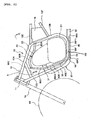
- the leg shield 108 opens forward, and is a rectangular shape in a front view (see FIG. 7 ). Also, the leg shield 108 is formed to gradually taper forward.
- FIG. 7 shows ridge lines 108B and 108C of the leg shield 108.
- the engine 130 is a single cylinder four-cycle engine, and includes a crankcase 131 for housing a crankshaft and a transmission inside and a cylinder 132 provided on an upper part of the crankcase 131 and having a cylinder body inside.
- An intake port for inducting air and fuel into the engine 130 is formed in the cylinder 132.
- a manifold is connected to the intake port.
- a throttle body 135, in which an injector is provided, is connected to a part upstream of the manifold.
- a combustion chamber for combusting fuel supplied from the intake port with air is formed inside the cylinder 132.
- Exhaust gas generated by combustion of fuel is discharged outside the engine 130 from an exhaust port formed in a front part of the cylinder 132.
- An exhaust conduit 150 is connected to the exhaust port formed in the cylinder 132.
- the exhaust conduit 150 extends forward obliquely downward from the exhaust port, then curves, and further extends rearward obliquely downward. Thereafter, the exhaust conduit 150 further curves and extends rearward below the crankcase 131.
- a part of the exhaust conduit 150 more rearward than the crankcase 131 is housed in a silencer 140 disposed on a side of the rear wheel 121.
- a front catalyzer housing part 151 and a rear catalyzer housing part 152 disposed more downstream than the front catalyzer housing part 151 are provided in the exhaust conduit 150.
- the front catalyzer housing part 151 has a front catalyzer 151A mainly having reducing effect inside.
- the rear catalyzer housing part 152 has a rear catalyzer 152A mainly having oxidizing effect inside.
- a secondary air inducting conduit 160 for supplying secondary air for exhaust gas is connected to the exhaust conduit 150.
- a downstream part (a part close to the exhaust conduit 150) of the secondary air inducting conduit 160 is disposed more forward than the crankcase 131 and above a lower surface of the crankcase 131. Its downstream end is connected to a part of the exhaust conduit 150 disposed more forward than the crankcase 131.
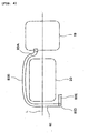
- the secondary air inducting conduit 160 includes a first conduit section 160A extending inward in the vehicle width direction from its connection part with the front catalyzer housing part 151 and then curvedly extending upward of the vehicle, a second conduit section 160B curving upward from the first conduit section 160A in a crank shape and connected to a reed valve assembly 161 disposed on a side of the engine 130 at its upstream end, and a third conduit section 160C extending rearward from the reed valve assembly 161 and connected to an air cleaner (not shown).
- first conduit section 160A and the second conduit section 160B of the secondary air inducting conduit 160 are exposed to an inside of a space S1 formed on a front part of the vehicle body and in the rear of the front wheel 23, and construct the secondary air cooling conduit.
- first conduit section 160A and the second conduit section 160B are disposed in positions that can be visually recognized from the front of the vehicle through an opening end 108D in front of the leg shield 108.
- an opening is formed on a side surface of the third conduit section 160C for connecting the reed valve assembly 161 and the air cleaner together.
- a box-shaped resonator 165 mounted on a lower part of the throttle body 135 is connected to the opening.
- a part of secondary air flowing into the exhaust conduit 150 flows from the third conduit section 160C into the resonator 165.
- the first conduit section 160A and the second conduit section 160B of the secondary air inducting conduit 160 are exposed to an inside of the space S1 formed on a front part of the vehicle body and in the rear of the front wheel 23.
- the secondary air inducting conduit 160 can be effectively cooled down, and the effect generally the same as the first embodiment can be realized.
- FIG. 9 shows a third embodiment of the present teaching but does not illustrate the combination of the features of independent claim 1.
- the same reference numerals and symbols are given to the parts same as FIGs.6 through 8 , and detailed descriptions will not be made hereinafter.
- an upstream end of a secondary air inducting conduit 263 is connected to a part of an exhaust conduit 50 between a front catalyzer housing part 51 and a rear catalyzer housing part 52.
- a downstream end of the secondary air inducting conduit 263 is connected to an air cleaner (not shown).
- the secondary air inducting conduit 263 is disposed to be exposed to a space on a side of the vehicle body in the rear of a front wheel 123.
- the secondary air inducting conduit 263 is disposed in a position that can be visually recognized from a side of the vehicle.
- the secondary air inducting conduit 263 is disposed to be exposed to the space on a side of the vehicle in the rear of the front wheel 123. Therefore, the secondary air inducting conduit 263 can be effectively cooled down, and the effect generally the same as the first embodiment can be realized.
- the present teaching is not limited to this construction, but also can be applied to straddle type vehicles, for example, unit swing type vehicles, in which an entire engine unit swings together with a rear wheel, such as many scooters.
- a motorcycle as a straddle type vehicle as an example.
- the present teaching is not limited to motorcycles, but also can be applied to other straddle type vehicles, for example, three-wheeled motor vehicles, buggies, and so forth.
- an embodiment of a straddle type vehicle including: an engine disposed between a front wheel and a rear wheel, a front catalytic converter and a rear catalytic converter spaced apart in the fore to aft direction in a midway part of an exhaust conduit of the engine, and a secondary air inducting conduit, of which a downstream end is connected to the exhaust conduit in a position between the front catalytic converter and the rear catalytic converter, in which a part of the secondary air inducting conduit is a secondary air cooling conduit section exposed at least either forward or sideward of the vehicle in the rear of the front wheel.
- the secondary air cooling conduit section which is a part of the secondary air inducting conduit, is exposed at least either forward or sideward of the vehicle in the rear of the front wheel.
- the secondary air cooling conduit section can be effectively cooled down, and an oxygen concentration of secondary air flowing through the secondary air cooling conduit section can be increased.
- combustion efficiency of exhaust gas by secondary air can be sufficiently enhanced when secondary air inducted from the secondary air inducting conduit to the exhaust conduit flows through the rear catalyzer.
- the secondary air cooling conduit section can be provided in a position more forward than the engine.
- a contact of a rearward hot air flow from the engine due to traveling with the secondary air cooling conduit section can be prevented. Thereby, without being affected by heat of the engine, the secondary air cooling conduit section can be more efficiently cooled down.
- an air cleaner can be disposed more rearward than the engine, and an upstream end of the secondary air inducting conduit can be connected to the air cleaner.
- the secondary air cooling conduit section can be formed with a metal pipe.
- the secondary air cooling conduit section can be formed with a metal pipe, which has high thermal conductivity. Thereby, secondary air flowing through the secondary air cooling conduit section can be more effectively cooled down.
- connection part of the secondary air inducting conduit which is connected to the exhaust conduit, can be disposed below the engine, and the secondary air inducting conduit can be formed to extend from the connection part in the horizontal direction below the engine.
- the secondary air inducting conduit can be lengthened to extend upstream from the connection part to the exhaust conduit in the horizontal direction, and thereby a sufficient length can be obtained for the inducting pipe for cooling down secondary air flowing in the secondary air inducting conduit. Accordingly, secondary air can be more efficiently cooled down.
- the secondary air inducting conduit can be formed to extend from either one of the right side and the left side to the other side traversing a center of the vehicle.
- the secondary air inducting conduit can be formed to extend from either one of the right side and the left side to the other side traversing a center of the vehicle, and thus an entire length of the secondary air inducting conduit can be enlarged. Thereby, secondary air flowing in the secondary air inducting conduit can be sufficiently cooled down.
- the frame is formed with right and left frames
- at least a part of the secondary air inducting conduit can be disposed to overlap the right and left frames in a side view.
- the secondary air inducting conduit can be protected from shocks from outside and so forth by the right and left frames.
- the straddle type vehicle has a construction such that the secondary air cooling conduit section of the secondary air inducting conduit is exposed at least either forward or sideward of the vehicle in the rear of the front wheel.
- an oxygen concentration of secondary air flowing through the secondary air cooling conduit section can be increased. Therefore, combustion efficiency of exhaust gas by secondary air can be sufficiently enhanced when secondary air inducted from the secondary air inducting conduit to the exhaust conduit flows through the rear catalyzer, and further assures purification of exhaust gas by the rear catalyzer.
- the description further discloses, according to a preferred first aspect, an engine disposed between a front wheel and a rear wheel; a front catalytic converter and a rear catalytic converter spaced apart in the fore to aft direction in a midway part of an exhaust conduit of the engine; and a secondary air inducting conduit, of which a downstream end is connected to the exhaust conduit in a position between the front catalytic converter and the rear catalytic converter, wherein a part of the secondary air inducting conduit is a secondary air cooling conduit section exposed at least either forward or sideward in the vehicle in the rear of the front wheel.
- the secondary air cooling conduit section is provided in a position more forward than the engine.
- At least a part of an air cleaner is disposed more rearward than the engine, and an upstream end of the secondary air inducting conduit is connected to the air cleaner.
- the secondary air cooling conduit section is formed with a metal pipe.
- connection part of the secondary air inducting conduit which is connected to the exhaust conduit, is disposed below the engine, and the secondary air inducting conduit is formed to extend from the connection part in the horizontal direction below the engine.
- the secondary air inducting conduit is formed to extend from either one of the right side and the left side to the other side traversing a center of the vehicle.
- a frame is formed with right and left frames, at least a part of the secondary air inducting conduit is disposed to overlap the right and left frames in a side view.
- the description still further discloses, in order to realize effective cooling of oxygen in air flowing through a secondary air inducting conduit, and enhance combustion efficiency of exhaust gas by secondary air in a catalyzer, according to a particularly preferred embodiment, that third through fifth conduit sections 80C through 80E of a secondary air inducting conduit 80 are exposed to a space S in the rear of a front wheel 60 and in front of an engine 20, and thus the third through the fifth conduit sections 80C through 80E become a secondary air cooling conduit section for cooling down secondary air.
- secondary air flowing through the secondary air inducting conduit is cooled down by the third through the fifth conduit sections 80C through 80E, and an oxygen concentration of secondary air is increased.
Landscapes
- Engineering & Computer Science (AREA)
- Chemical & Material Sciences (AREA)
- Mechanical Engineering (AREA)
- Chemical Kinetics & Catalysis (AREA)
- Combustion & Propulsion (AREA)
- General Engineering & Computer Science (AREA)
- Health & Medical Sciences (AREA)
- Toxicology (AREA)
- Exhaust Gas After Treatment (AREA)
- Axle Suspensions And Sidecars For Cycles (AREA)
- Motor Or Generator Cooling System (AREA)
- Cooling, Air Intake And Gas Exhaust, And Fuel Tank Arrangements In Propulsion Units (AREA)
Claims (6)
- Fahrzeug vom Spreizsitz- Typ, aufweisend eine Brennkraftmaschine (20), angeordnet zwischen vorderen und hinteren Rädern, und einem ersten und einem zweiten katalytischen Wandler (40, 50), angeordnet in einer Abgasleitung (30) der Brennkraftmaschine (20), wobei eine Sekundärluft- Einleitungsleitung (80) zum Zuführen von Sekundärluft in die Abgasleitung (30) an einer Position zwischen dem ersten und dem zweiten katalytischen Wandler (40, 50) vorgesehen ist,
wobei ein Teil der Sekundärluft- Einleitungsleitung (80) in einer Position weiter vorn als die Brennkraftmaschine (20) und hinter dem Vorderrad vorgesehen ist und zumindest ein Teil des Luftfilters (19) weiter hinten als die Brennkraftmaschine (20) angeordnet ist und ein stromaufwärtiges Ende (80A) der Sekundärluft- Einleitungsleitung (80) mit dem Luftfilter (19) verbunden ist. - Fahrzeug vom Spreizsitz- Typ nach Anspruch 1, wobei der erste und zweite katalytischen Wandler (40, 50) ein vorderer katalytischer Wandler (40) und ein hinterer katalytischer Wandler (50) ist, beabstandet in der Vorwärts-Rückwärts-Richtung in einem mittleren Teil (34) einer Abgasleitung (30) der Brennkraftmaschine (20), und ein stromabwärtiges Ende (80G) der Sekundärluft- Einleitungsleitung (80) mit der Abgasleitung (30) in einer Position zwischen dem vorderen katalytischen Wandler (40) und dem hinteren katalytischen Wandler (50) verbunden ist.
- Fahrzeug vom Spreizsitz- Typ nach Anspruch 1 oder 2, wobei der Sekundärluft- Einleitungsabschnitt zumindest teilweise mit einem Metallrohr gebildet ist.
- Fahrzeug vom Spreizsitz- Typ nach zumindest einem der Ansprüche 1 bis 3, wobei ein Verbindungsteil (80G1) der Sekundärluft- Einleitungsleitung (80), das mit der Abgasleitung (30) verbunden ist, unter der Brennkraftmaschine (20) angeordnet ist und die Sekundärluft- Einleitungsleitung (80) ausgebildet ist, sich von dem Verbindungsteil (80G1) in der horizontalen Richtung unter der Brennkraftmaschine (20) zu erstrecken.
- Fahrzeug vom Spreizsitz- Typ nach Anspruch 4, wobei ein Teil (80C) der Sekundärluft- Einleitungsleitung (80) ausgebildet ist, sich von einer Seite der rechten Seite oder der linken Seite zu der anderen Seite, eine Mitte des Fahrzeuges überquerend, zu erstrecken.
- Fahrzeug vom Spreizsitz- Typ nach zumindest einem der Ansprüche 1 bis 5, wobei ein Rahmen mit einem rechten und einem linken Rahmen (12, 13) gebildet ist, wobei zumindest ein Teil (80E) der Sekundärluft- Einleitungsleitung (80) vorgesehen ist, dem rechten und linken Rahmen in einer Seitensicht zu überlappen.
Applications Claiming Priority (1)
| Application Number | Priority Date | Filing Date | Title |
|---|---|---|---|
| JP2006330004A JP4871107B2 (ja) | 2006-12-06 | 2006-12-06 | 鞍乗り型車両 |
Publications (2)
| Publication Number | Publication Date |
|---|---|
| EP1933010A1 EP1933010A1 (de) | 2008-06-18 |
| EP1933010B1 true EP1933010B1 (de) | 2010-06-23 |
Family
ID=39027553
Family Applications (1)
| Application Number | Title | Priority Date | Filing Date |
|---|---|---|---|
| EP07023188A Not-in-force EP1933010B1 (de) | 2006-12-06 | 2007-11-29 | Motorrad |
Country Status (8)
| Country | Link |
|---|---|
| US (1) | US8439142B2 (de) |
| EP (1) | EP1933010B1 (de) |
| JP (1) | JP4871107B2 (de) |
| CN (1) | CN101239642B (de) |
| AT (1) | ATE472048T1 (de) |
| BR (1) | BRPI0704401B1 (de) |
| DE (1) | DE602007007283D1 (de) |
| ES (1) | ES2346357T3 (de) |
Families Citing this family (10)
| Publication number | Priority date | Publication date | Assignee | Title |
|---|---|---|---|---|
| ES2359470T3 (es) * | 2008-08-29 | 2011-05-23 | YAMAHA MOTOR RESEARCH & DEVELOPMENT EUROPE S.R.L. (YMRE) | Aparato de purificar gases de escape para una motocicleta y una motocleta equipada con dicho aparato de purificación de gases de escape. |
| JP5362694B2 (ja) * | 2010-12-07 | 2013-12-11 | 本田技研工業株式会社 | 鞍乗型車両 |
| CN102996296B (zh) * | 2011-09-16 | 2015-07-01 | 雅马哈发动机株式会社 | 摩托车 |
| JP6231751B2 (ja) * | 2013-01-30 | 2017-11-15 | 本田技研工業株式会社 | 自動二輪車の排気ガスセンサ配置構造 |
| JP2017150311A (ja) * | 2014-07-04 | 2017-08-31 | ヤマハ発動機株式会社 | エンジンユニット及び鞍乗型車両 |
| JP2017150309A (ja) * | 2014-07-04 | 2017-08-31 | ヤマハ発動機株式会社 | エンジンユニットおよび鞍乗型車両 |
| WO2016098900A1 (ja) * | 2014-12-19 | 2016-06-23 | ヤマハ発動機株式会社 | 鞍乗型車両 |
| JP2020131839A (ja) * | 2019-02-15 | 2020-08-31 | 本田技研工業株式会社 | 車両の吸気ダクト構造 |
| CN114605040A (zh) * | 2022-03-31 | 2022-06-10 | 青岛宝菲尔物流装备有限公司 | 一种水处理集装箱 |
| JP2025015167A (ja) * | 2023-07-20 | 2025-01-30 | スズキ株式会社 | 空気制御装置の設置構造 |
Family Cites Families (28)
| Publication number | Priority date | Publication date | Assignee | Title |
|---|---|---|---|---|
| US3061416A (en) * | 1957-11-22 | 1962-10-30 | George P Kazokas | Catalytic muffler |
| US3672172A (en) * | 1971-03-15 | 1972-06-27 | Gary L Hammond | Simplified supercharged internal combustion engine with emissions control |
| GB1469527A (en) * | 1973-03-30 | 1977-04-06 | Atomic Energy Authority Uk | Manufacture of catalysts |
| JPS52102920A (en) * | 1976-02-26 | 1977-08-29 | Toyota Motor Corp | Secondary-air supply system for exhaust gas cleaner |
| JPS5741416A (en) * | 1980-08-22 | 1982-03-08 | Honda Motor Co Ltd | Discharge gas cleaner of internal combustion engine with multi-cylinder for motorcycle |
| JPS5832913A (ja) * | 1981-08-24 | 1983-02-26 | Honda Motor Co Ltd | 内燃機関における排気浄化装置 |
| JPS595709U (ja) * | 1982-07-05 | 1984-01-14 | 本田技研工業株式会社 | 自動二輪車用排気浄化装置の二次空気供給装置 |
| JPS62284917A (ja) * | 1986-06-02 | 1987-12-10 | Yamaha Motor Co Ltd | 自動二輪車の排気浄化用二次空気供給装置 |
| JPH04140413A (ja) * | 1990-10-01 | 1992-05-14 | Yamaha Motor Co Ltd | 内燃機関の排気ガス浄化装置 |
| JP3008488B2 (ja) * | 1990-11-22 | 2000-02-14 | スズキ株式会社 | 二サイクルエンジンの二次空気供給装置 |
| JP3314241B2 (ja) | 1992-04-06 | 2002-08-12 | ヤマハ発動機株式会社 | 自動二輪車用エンジンの排気浄化装置 |
| JP3302047B2 (ja) * | 1992-06-19 | 2002-07-15 | ヤマハ発動機株式会社 | 自動二輪車の排気浄化装置 |
| JP3281190B2 (ja) * | 1994-07-27 | 2002-05-13 | ヤマハ発動機株式会社 | 自動二輪車用内燃機関の排気浄化装置 |
| JP3616683B2 (ja) * | 1995-11-16 | 2005-02-02 | 本田技研工業株式会社 | 内燃エンジンのエアポンプの異常検出装置 |
| JP4540762B2 (ja) * | 1999-01-18 | 2010-09-08 | 本田技研工業株式会社 | 排気2次空気弁を備えた鞍乗型車両 |
| JP3631035B2 (ja) * | 1999-02-22 | 2005-03-23 | 本田技研工業株式会社 | 内燃機関の排気2次空気供給制御装置 |
| JP2000282855A (ja) * | 1999-03-29 | 2000-10-10 | Yamaha Motor Co Ltd | 鞍乗型車両の排気浄化装置 |
| JP3427824B2 (ja) | 2000-09-18 | 2003-07-22 | スズキ株式会社 | スクータの排気ガス浄化装置 |
| DE10048580A1 (de) * | 2000-09-30 | 2002-04-11 | Volkswagen Ag | Abgasanlage einer Brennkraftmaschine mit Katalysator |
| JP2002161737A (ja) * | 2000-11-29 | 2002-06-07 | Sanshin Ind Co Ltd | エンジンにおける排気浄化装置、およびこの装置を搭載した小型船舶 |
| FR2827908B1 (fr) * | 2001-07-26 | 2004-02-13 | Peugeot Motocycles Sa | Systeme de purification des gaz d'echappement d'un moteur thermique a deux temps, notamment pour vehicule a deux roues |
| JP4177157B2 (ja) * | 2003-04-24 | 2008-11-05 | トヨタ自動車株式会社 | 二次空気供給装置の異常判定装置 |
| MY141622A (en) * | 2003-06-19 | 2010-05-31 | Yamaha Motor Co Ltd | Exhaust system for an engine |
| JP2005138820A (ja) * | 2003-10-16 | 2005-06-02 | Yamaha Motor Co Ltd | 鞍乗り型車両 |
| ATE513120T1 (de) * | 2004-02-24 | 2011-07-15 | Yamaha Motor Co Ltd | Abgasreinigungsvorrichtung für einen motor |
| US7263826B2 (en) * | 2004-07-13 | 2007-09-04 | Sentec E&E Co., Ltd. | Muffler device with catalysts for improving purifying exhaust gas of nitrogen oxides within a motorcycle exhaust pipe |
| JP4545013B2 (ja) * | 2005-02-21 | 2010-09-15 | 本田技研工業株式会社 | 自動2輪車の排気2次エア導入構造 |
| JP2007040249A (ja) | 2005-08-04 | 2007-02-15 | Yamaha Motor Co Ltd | 排気ガス浄化機能を有するエンジン及び車両 |
-
2006
- 2006-12-06 JP JP2006330004A patent/JP4871107B2/ja not_active Expired - Fee Related
-
2007
- 2007-11-29 DE DE602007007283T patent/DE602007007283D1/de active Active
- 2007-11-29 ES ES07023188T patent/ES2346357T3/es active Active
- 2007-11-29 EP EP07023188A patent/EP1933010B1/de not_active Not-in-force
- 2007-11-29 AT AT07023188T patent/ATE472048T1/de not_active IP Right Cessation
- 2007-12-03 BR BRPI0704401-1A patent/BRPI0704401B1/pt not_active IP Right Cessation
- 2007-12-04 CN CN2007101865085A patent/CN101239642B/zh not_active Expired - Fee Related
- 2007-12-05 US US11/951,220 patent/US8439142B2/en not_active Expired - Fee Related
Also Published As
| Publication number | Publication date |
|---|---|
| US20080135317A1 (en) | 2008-06-12 |
| US8439142B2 (en) | 2013-05-14 |
| EP1933010A1 (de) | 2008-06-18 |
| CN101239642B (zh) | 2011-06-08 |
| BRPI0704401A (pt) | 2008-07-22 |
| CN101239642A (zh) | 2008-08-13 |
| DE602007007283D1 (de) | 2010-08-05 |
| ES2346357T3 (es) | 2010-10-14 |
| ATE472048T1 (de) | 2010-07-15 |
| BRPI0704401B1 (pt) | 2019-07-16 |
| JP4871107B2 (ja) | 2012-02-08 |
| JP2008144613A (ja) | 2008-06-26 |
Similar Documents
| Publication | Publication Date | Title |
|---|---|---|
| US8439142B2 (en) | Straddle type vehicle | |
| US7882700B2 (en) | Exhaust pipe structure | |
| US20120267182A1 (en) | Motorcycle with supercharger | |
| US8584788B2 (en) | Exhaust system for motorcycle | |
| US7513328B2 (en) | Cowling of motorcycle | |
| EP2159393B1 (de) | Abgasreinigungsvorrichtung für ein Motorrad und mit einer solchen Abgasreinigungsvorrichtung ausgestattetes Motorrad | |
| JPS6353193A (ja) | 自動二輪車のエアクリーナ装置 | |
| JP2002303133A (ja) | 自動二輪車の排気系構造 | |
| EP1749988B1 (de) | Abgasreinigungssystem | |
| US8074756B2 (en) | Straddle-type rough-road running vehicle | |
| US6382197B1 (en) | Secondary air supply system for engine of motorcycle | |
| JP2000204939A (ja) | 排気2次空気弁を備えた鞍乗型車両 | |
| JP4151261B2 (ja) | 小型車両のエンジン排気装置 | |
| US7896124B2 (en) | Exhaust systems and motorcycles including same | |
| JP3143323U (ja) | 排気ガス浄化機能を有する鞍乗型車両 | |
| JP2007040250A (ja) | 排気ガス浄化機能を有する鞍乗型車両 | |
| JP3890898B2 (ja) | スクータ型自動二輪車の2次空気供給装置 | |
| JP7491176B2 (ja) | 二次エア供給装置 | |
| EP4545764B1 (de) | Motor | |
| JP7819572B2 (ja) | 鞍乗型車両 | |
| CN223072674U (zh) | 鞍乘型车辆 | |
| US20260002500A1 (en) | Cover structure | |
| US20260091840A1 (en) | Saddled vehicle | |
| JP7275775B2 (ja) | 自動二輪車 | |
| JP2007118653A (ja) | 鞍乗型車両のエンジン冷却構造 |
Legal Events
| Date | Code | Title | Description |
|---|---|---|---|
| PUAI | Public reference made under article 153(3) epc to a published international application that has entered the european phase |
Free format text: ORIGINAL CODE: 0009012 |
|
| 17P | Request for examination filed |
Effective date: 20080319 |
|
| AK | Designated contracting states |
Kind code of ref document: A1 Designated state(s): AT BE BG CH CY CZ DE DK EE ES FI FR GB GR HU IE IS IT LI LT LU LV MC MT NL PL PT RO SE SI SK TR |
|
| AX | Request for extension of the european patent |
Extension state: AL BA HR MK RS |
|
| 17Q | First examination report despatched |
Effective date: 20080728 |
|
| AKX | Designation fees paid |
Designated state(s): AT BE BG CH CY CZ DE DK EE ES FI FR GB GR HU IE IS IT LI LT LU LV MC MT NL PL PT RO SE SI SK TR |
|
| GRAP | Despatch of communication of intention to grant a patent |
Free format text: ORIGINAL CODE: EPIDOSNIGR1 |
|
| GRAC | Information related to communication of intention to grant a patent modified |
Free format text: ORIGINAL CODE: EPIDOSCIGR1 |
|
| GRAS | Grant fee paid |
Free format text: ORIGINAL CODE: EPIDOSNIGR3 |
|
| GRAA | (expected) grant |
Free format text: ORIGINAL CODE: 0009210 |
|
| AK | Designated contracting states |
Kind code of ref document: B1 Designated state(s): AT BE BG CH CY CZ DE DK EE ES FI FR GB GR HU IE IS IT LI LT LU LV MC MT NL PL PT RO SE SI SK TR |
|
| REG | Reference to a national code |
Ref country code: CH Ref legal event code: EP |
|
| REG | Reference to a national code |
Ref country code: IE Ref legal event code: FG4D |
|
| REF | Corresponds to: |
Ref document number: 602007007283 Country of ref document: DE Date of ref document: 20100805 Kind code of ref document: P |
|
| REG | Reference to a national code |
Ref country code: ES Ref legal event code: FG2A Ref document number: 2346357 Country of ref document: ES Kind code of ref document: T3 |
|
| REG | Reference to a national code |
Ref country code: NL Ref legal event code: VDEP Effective date: 20100623 |
|
| PG25 | Lapsed in a contracting state [announced via postgrant information from national office to epo] |
Ref country code: LT Free format text: LAPSE BECAUSE OF FAILURE TO SUBMIT A TRANSLATION OF THE DESCRIPTION OR TO PAY THE FEE WITHIN THE PRESCRIBED TIME-LIMIT Effective date: 20100623 Ref country code: SE Free format text: LAPSE BECAUSE OF FAILURE TO SUBMIT A TRANSLATION OF THE DESCRIPTION OR TO PAY THE FEE WITHIN THE PRESCRIBED TIME-LIMIT Effective date: 20100623 |
|
| LTIE | Lt: invalidation of european patent or patent extension |
Effective date: 20100623 |
|
| PG25 | Lapsed in a contracting state [announced via postgrant information from national office to epo] |
Ref country code: FI Free format text: LAPSE BECAUSE OF FAILURE TO SUBMIT A TRANSLATION OF THE DESCRIPTION OR TO PAY THE FEE WITHIN THE PRESCRIBED TIME-LIMIT Effective date: 20100623 Ref country code: LV Free format text: LAPSE BECAUSE OF FAILURE TO SUBMIT A TRANSLATION OF THE DESCRIPTION OR TO PAY THE FEE WITHIN THE PRESCRIBED TIME-LIMIT Effective date: 20100623 Ref country code: SI Free format text: LAPSE BECAUSE OF FAILURE TO SUBMIT A TRANSLATION OF THE DESCRIPTION OR TO PAY THE FEE WITHIN THE PRESCRIBED TIME-LIMIT Effective date: 20100623 Ref country code: AT Free format text: LAPSE BECAUSE OF FAILURE TO SUBMIT A TRANSLATION OF THE DESCRIPTION OR TO PAY THE FEE WITHIN THE PRESCRIBED TIME-LIMIT Effective date: 20100623 |
|
| PG25 | Lapsed in a contracting state [announced via postgrant information from national office to epo] |
Ref country code: PL Free format text: LAPSE BECAUSE OF FAILURE TO SUBMIT A TRANSLATION OF THE DESCRIPTION OR TO PAY THE FEE WITHIN THE PRESCRIBED TIME-LIMIT Effective date: 20100623 |
|
| PG25 | Lapsed in a contracting state [announced via postgrant information from national office to epo] |
Ref country code: GR Free format text: LAPSE BECAUSE OF FAILURE TO SUBMIT A TRANSLATION OF THE DESCRIPTION OR TO PAY THE FEE WITHIN THE PRESCRIBED TIME-LIMIT Effective date: 20100924 Ref country code: EE Free format text: LAPSE BECAUSE OF FAILURE TO SUBMIT A TRANSLATION OF THE DESCRIPTION OR TO PAY THE FEE WITHIN THE PRESCRIBED TIME-LIMIT Effective date: 20100623 Ref country code: NL Free format text: LAPSE BECAUSE OF FAILURE TO SUBMIT A TRANSLATION OF THE DESCRIPTION OR TO PAY THE FEE WITHIN THE PRESCRIBED TIME-LIMIT Effective date: 20100623 |
|
| PG25 | Lapsed in a contracting state [announced via postgrant information from national office to epo] |
Ref country code: SK Free format text: LAPSE BECAUSE OF FAILURE TO SUBMIT A TRANSLATION OF THE DESCRIPTION OR TO PAY THE FEE WITHIN THE PRESCRIBED TIME-LIMIT Effective date: 20100623 Ref country code: PT Free format text: LAPSE BECAUSE OF FAILURE TO SUBMIT A TRANSLATION OF THE DESCRIPTION OR TO PAY THE FEE WITHIN THE PRESCRIBED TIME-LIMIT Effective date: 20101025 Ref country code: RO Free format text: LAPSE BECAUSE OF FAILURE TO SUBMIT A TRANSLATION OF THE DESCRIPTION OR TO PAY THE FEE WITHIN THE PRESCRIBED TIME-LIMIT Effective date: 20100623 Ref country code: BE Free format text: LAPSE BECAUSE OF FAILURE TO SUBMIT A TRANSLATION OF THE DESCRIPTION OR TO PAY THE FEE WITHIN THE PRESCRIBED TIME-LIMIT Effective date: 20100623 Ref country code: CY Free format text: LAPSE BECAUSE OF FAILURE TO SUBMIT A TRANSLATION OF THE DESCRIPTION OR TO PAY THE FEE WITHIN THE PRESCRIBED TIME-LIMIT Effective date: 20100623 Ref country code: CZ Free format text: LAPSE BECAUSE OF FAILURE TO SUBMIT A TRANSLATION OF THE DESCRIPTION OR TO PAY THE FEE WITHIN THE PRESCRIBED TIME-LIMIT Effective date: 20100623 Ref country code: IS Free format text: LAPSE BECAUSE OF FAILURE TO SUBMIT A TRANSLATION OF THE DESCRIPTION OR TO PAY THE FEE WITHIN THE PRESCRIBED TIME-LIMIT Effective date: 20101023 |
|
| PG25 | Lapsed in a contracting state [announced via postgrant information from national office to epo] |
Ref country code: DK Free format text: LAPSE BECAUSE OF FAILURE TO SUBMIT A TRANSLATION OF THE DESCRIPTION OR TO PAY THE FEE WITHIN THE PRESCRIBED TIME-LIMIT Effective date: 20100623 |
|
| PLBE | No opposition filed within time limit |
Free format text: ORIGINAL CODE: 0009261 |
|
| STAA | Information on the status of an ep patent application or granted ep patent |
Free format text: STATUS: NO OPPOSITION FILED WITHIN TIME LIMIT |
|
| 26N | No opposition filed |
Effective date: 20110324 |
|
| PG25 | Lapsed in a contracting state [announced via postgrant information from national office to epo] |
Ref country code: MC Free format text: LAPSE BECAUSE OF NON-PAYMENT OF DUE FEES Effective date: 20101130 |
|
| REG | Reference to a national code |
Ref country code: DE Ref legal event code: R097 Ref document number: 602007007283 Country of ref document: DE Effective date: 20110323 |
|
| PG25 | Lapsed in a contracting state [announced via postgrant information from national office to epo] |
Ref country code: IE Free format text: LAPSE BECAUSE OF NON-PAYMENT OF DUE FEES Effective date: 20101129 |
|
| PG25 | Lapsed in a contracting state [announced via postgrant information from national office to epo] |
Ref country code: IT Free format text: LAPSE BECAUSE OF NON-PAYMENT OF DUE FEES Effective date: 20101129 Ref country code: MT Free format text: LAPSE BECAUSE OF FAILURE TO SUBMIT A TRANSLATION OF THE DESCRIPTION OR TO PAY THE FEE WITHIN THE PRESCRIBED TIME-LIMIT Effective date: 20100623 |
|
| REG | Reference to a national code |
Ref country code: CH Ref legal event code: PL |
|
| PG25 | Lapsed in a contracting state [announced via postgrant information from national office to epo] |
Ref country code: LI Free format text: LAPSE BECAUSE OF NON-PAYMENT OF DUE FEES Effective date: 20111130 Ref country code: CH Free format text: LAPSE BECAUSE OF NON-PAYMENT OF DUE FEES Effective date: 20111130 |
|
| PG25 | Lapsed in a contracting state [announced via postgrant information from national office to epo] |
Ref country code: HU Free format text: LAPSE BECAUSE OF FAILURE TO SUBMIT A TRANSLATION OF THE DESCRIPTION OR TO PAY THE FEE WITHIN THE PRESCRIBED TIME-LIMIT Effective date: 20101224 Ref country code: BG Free format text: LAPSE BECAUSE OF FAILURE TO SUBMIT A TRANSLATION OF THE DESCRIPTION OR TO PAY THE FEE WITHIN THE PRESCRIBED TIME-LIMIT Effective date: 20100623 Ref country code: LU Free format text: LAPSE BECAUSE OF NON-PAYMENT OF DUE FEES Effective date: 20101129 |
|
| PG25 | Lapsed in a contracting state [announced via postgrant information from national office to epo] |
Ref country code: TR Free format text: LAPSE BECAUSE OF FAILURE TO SUBMIT A TRANSLATION OF THE DESCRIPTION OR TO PAY THE FEE WITHIN THE PRESCRIBED TIME-LIMIT Effective date: 20100623 |
|
| PG25 | Lapsed in a contracting state [announced via postgrant information from national office to epo] |
Ref country code: BG Free format text: LAPSE BECAUSE OF FAILURE TO SUBMIT A TRANSLATION OF THE DESCRIPTION OR TO PAY THE FEE WITHIN THE PRESCRIBED TIME-LIMIT Effective date: 20100923 |
|
| REG | Reference to a national code |
Ref country code: FR Ref legal event code: PLFP Year of fee payment: 9 |
|
| REG | Reference to a national code |
Ref country code: FR Ref legal event code: PLFP Year of fee payment: 10 |
|
| REG | Reference to a national code |
Ref country code: FR Ref legal event code: PLFP Year of fee payment: 11 |
|
| PGFP | Annual fee paid to national office [announced via postgrant information from national office to epo] |
Ref country code: IT Payment date: 20221124 Year of fee payment: 16 Ref country code: GB Payment date: 20221122 Year of fee payment: 16 Ref country code: FR Payment date: 20221128 Year of fee payment: 16 Ref country code: DE Payment date: 20220620 Year of fee payment: 16 |
|
| PGFP | Annual fee paid to national office [announced via postgrant information from national office to epo] |
Ref country code: ES Payment date: 20230125 Year of fee payment: 16 |
|
| REG | Reference to a national code |
Ref country code: DE Ref legal event code: R119 Ref document number: 602007007283 Country of ref document: DE |
|
| GBPC | Gb: european patent ceased through non-payment of renewal fee |
Effective date: 20231129 |
|
| PG25 | Lapsed in a contracting state [announced via postgrant information from national office to epo] |
Ref country code: DE Free format text: LAPSE BECAUSE OF NON-PAYMENT OF DUE FEES Effective date: 20240601 |
|
| PG25 | Lapsed in a contracting state [announced via postgrant information from national office to epo] |
Ref country code: GB Free format text: LAPSE BECAUSE OF NON-PAYMENT OF DUE FEES Effective date: 20231129 |
|
| PG25 | Lapsed in a contracting state [announced via postgrant information from national office to epo] |
Ref country code: FR Free format text: LAPSE BECAUSE OF NON-PAYMENT OF DUE FEES Effective date: 20231130 |
|
| PG25 | Lapsed in a contracting state [announced via postgrant information from national office to epo] |
Ref country code: GB Free format text: LAPSE BECAUSE OF NON-PAYMENT OF DUE FEES Effective date: 20231129 Ref country code: FR Free format text: LAPSE BECAUSE OF NON-PAYMENT OF DUE FEES Effective date: 20231130 Ref country code: DE Free format text: LAPSE BECAUSE OF NON-PAYMENT OF DUE FEES Effective date: 20240601 |
|
| PG25 | Lapsed in a contracting state [announced via postgrant information from national office to epo] |
Ref country code: IT Free format text: LAPSE BECAUSE OF NON-PAYMENT OF DUE FEES Effective date: 20231129 |
|
| PG25 | Lapsed in a contracting state [announced via postgrant information from national office to epo] |
Ref country code: IT Free format text: LAPSE BECAUSE OF NON-PAYMENT OF DUE FEES Effective date: 20231129 |
|
| REG | Reference to a national code |
Ref country code: ES Ref legal event code: FD2A Effective date: 20250103 |
|
| PG25 | Lapsed in a contracting state [announced via postgrant information from national office to epo] |
Ref country code: ES Free format text: LAPSE BECAUSE OF NON-PAYMENT OF DUE FEES Effective date: 20231130 |
|
| PG25 | Lapsed in a contracting state [announced via postgrant information from national office to epo] |
Ref country code: ES Free format text: LAPSE BECAUSE OF NON-PAYMENT OF DUE FEES Effective date: 20231130 |