EP1928049A1 - Pile à combustible à oxyde solide mince - Google Patents
Pile à combustible à oxyde solide mince Download PDFInfo
- Publication number
- EP1928049A1 EP1928049A1 EP06024338A EP06024338A EP1928049A1 EP 1928049 A1 EP1928049 A1 EP 1928049A1 EP 06024338 A EP06024338 A EP 06024338A EP 06024338 A EP06024338 A EP 06024338A EP 1928049 A1 EP1928049 A1 EP 1928049A1
- Authority
- EP
- European Patent Office
- Prior art keywords
- layer
- electrolyte
- cell
- solid oxide
- thin
- Prior art date
- Legal status (The legal status is an assumption and is not a legal conclusion. Google has not performed a legal analysis and makes no representation as to the accuracy of the status listed.)
- Withdrawn
Links
- 239000007787 solid Substances 0.000 title claims abstract description 56
- 239000003792 electrolyte Substances 0.000 claims abstract description 82
- 239000012528 membrane Substances 0.000 claims abstract description 63
- 239000003054 catalyst Substances 0.000 claims abstract description 41
- 238000004519 manufacturing process Methods 0.000 claims abstract description 38
- 239000000463 material Substances 0.000 claims abstract description 37
- 238000000926 separation method Methods 0.000 claims abstract description 34
- 229910052751 metal Inorganic materials 0.000 claims abstract description 33
- 239000002184 metal Substances 0.000 claims abstract description 33
- 239000002001 electrolyte material Substances 0.000 claims abstract description 27
- MCMNRKCIXSYSNV-UHFFFAOYSA-N Zirconium dioxide Chemical compound O=[Zr]=O MCMNRKCIXSYSNV-UHFFFAOYSA-N 0.000 claims abstract description 16
- 239000004020 conductor Substances 0.000 claims abstract description 16
- 230000002441 reversible effect Effects 0.000 claims abstract description 14
- 239000002243 precursor Substances 0.000 claims description 33
- 239000000203 mixture Substances 0.000 claims description 28
- 238000010345 tape casting Methods 0.000 claims description 28
- CETPSERCERDGAM-UHFFFAOYSA-N ceric oxide Chemical compound O=[Ce]=O CETPSERCERDGAM-UHFFFAOYSA-N 0.000 claims description 26
- 229910000422 cerium(IV) oxide Inorganic materials 0.000 claims description 26
- 238000005245 sintering Methods 0.000 claims description 25
- 238000005470 impregnation Methods 0.000 claims description 24
- 239000000446 fuel Substances 0.000 claims description 16
- 238000000034 method Methods 0.000 claims description 15
- 229910052759 nickel Inorganic materials 0.000 claims description 15
- 229910052712 strontium Inorganic materials 0.000 claims description 11
- 229910052746 lanthanum Inorganic materials 0.000 claims description 9
- 229910045601 alloy Inorganic materials 0.000 claims description 6
- 239000000956 alloy Substances 0.000 claims description 6
- 229910052802 copper Inorganic materials 0.000 claims description 6
- 229910052748 manganese Inorganic materials 0.000 claims description 6
- 229910052750 molybdenum Inorganic materials 0.000 claims description 6
- 229910052721 tungsten Inorganic materials 0.000 claims description 6
- 229910052776 Thorium Inorganic materials 0.000 claims description 4
- 229910052770 Uranium Inorganic materials 0.000 claims description 4
- 229910052758 niobium Inorganic materials 0.000 claims description 4
- 229910052720 vanadium Inorganic materials 0.000 claims description 4
- 229910052684 Cerium Inorganic materials 0.000 claims description 3
- 239000012078 proton-conducting electrolyte Substances 0.000 claims description 3
- 229910052782 aluminium Inorganic materials 0.000 claims description 2
- 238000005096 rolling process Methods 0.000 claims description 2
- 229910052715 tantalum Inorganic materials 0.000 claims description 2
- 229910052719 titanium Inorganic materials 0.000 claims description 2
- 229910052727 yttrium Inorganic materials 0.000 claims description 2
- 229910052726 zirconium Inorganic materials 0.000 claims description 2
- 229910000859 α-Fe Inorganic materials 0.000 claims description 2
- 239000010410 layer Substances 0.000 description 348
- 239000000725 suspension Substances 0.000 description 59
- 238000010438 heat treatment Methods 0.000 description 34
- 230000008595 infiltration Effects 0.000 description 31
- 238000001764 infiltration Methods 0.000 description 31
- 239000000843 powder Substances 0.000 description 29
- XEEYBQQBJWHFJM-UHFFFAOYSA-N iron Substances [Fe] XEEYBQQBJWHFJM-UHFFFAOYSA-N 0.000 description 24
- LFQSCWFLJHTTHZ-UHFFFAOYSA-N Ethanol Chemical compound CCO LFQSCWFLJHTTHZ-UHFFFAOYSA-N 0.000 description 22
- 229920002037 poly(vinyl butyral) polymer Polymers 0.000 description 22
- 229920000036 polyvinylpyrrolidone Polymers 0.000 description 22
- 239000001267 polyvinylpyrrolidone Substances 0.000 description 22
- 235000013855 polyvinylpyrrolidone Nutrition 0.000 description 22
- 239000011888 foil Substances 0.000 description 21
- 239000002245 particle Substances 0.000 description 17
- 229910002651 NO3 Inorganic materials 0.000 description 15
- NHNBFGGVMKEFGY-UHFFFAOYSA-N Nitrate Chemical compound [O-][N+]([O-])=O NHNBFGGVMKEFGY-UHFFFAOYSA-N 0.000 description 15
- 238000000354 decomposition reaction Methods 0.000 description 15
- PXHVJJICTQNCMI-UHFFFAOYSA-N nickel Substances [Ni] PXHVJJICTQNCMI-UHFFFAOYSA-N 0.000 description 15
- 150000002823 nitrates Chemical group 0.000 description 15
- 239000000654 additive Substances 0.000 description 14
- 238000003475 lamination Methods 0.000 description 14
- 238000002791 soaking Methods 0.000 description 14
- QVGXLLKOCUKJST-UHFFFAOYSA-N atomic oxygen Chemical compound [O] QVGXLLKOCUKJST-UHFFFAOYSA-N 0.000 description 11
- 238000000498 ball milling Methods 0.000 description 11
- 238000001816 cooling Methods 0.000 description 11
- 239000001301 oxygen Substances 0.000 description 11
- 229910052760 oxygen Inorganic materials 0.000 description 11
- 238000004080 punching Methods 0.000 description 10
- 229910052688 Gadolinium Inorganic materials 0.000 description 9
- 238000005266 casting Methods 0.000 description 9
- 229910000604 Ferrochrome Inorganic materials 0.000 description 7
- 238000001035 drying Methods 0.000 description 7
- 239000007789 gas Substances 0.000 description 6
- 239000001257 hydrogen Substances 0.000 description 6
- 229910052739 hydrogen Inorganic materials 0.000 description 6
- 229910052742 iron Inorganic materials 0.000 description 6
- 239000000919 ceramic Substances 0.000 description 5
- 239000003610 charcoal Substances 0.000 description 5
- 239000000758 substrate Substances 0.000 description 5
- OKTJSMMVPCPJKN-UHFFFAOYSA-N Carbon Chemical compound [C] OKTJSMMVPCPJKN-UHFFFAOYSA-N 0.000 description 4
- 230000015572 biosynthetic process Effects 0.000 description 4
- 230000006835 compression Effects 0.000 description 4
- 238000007906 compression Methods 0.000 description 4
- 229910002804 graphite Inorganic materials 0.000 description 4
- 239000010439 graphite Substances 0.000 description 4
- 150000002431 hydrogen Chemical class 0.000 description 4
- VNWKTOKETHGBQD-UHFFFAOYSA-N methane Chemical compound C VNWKTOKETHGBQD-UHFFFAOYSA-N 0.000 description 4
- 238000003786 synthesis reaction Methods 0.000 description 4
- 239000010419 fine particle Substances 0.000 description 3
- 229910052763 palladium Inorganic materials 0.000 description 3
- 239000011148 porous material Substances 0.000 description 3
- 229910002449 CoO3−δ Inorganic materials 0.000 description 2
- UFHFLCQGNIYNRP-UHFFFAOYSA-N Hydrogen Chemical compound [H][H] UFHFLCQGNIYNRP-UHFFFAOYSA-N 0.000 description 2
- 230000000996 additive effect Effects 0.000 description 2
- 238000005868 electrolysis reaction Methods 0.000 description 2
- 238000010030 laminating Methods 0.000 description 2
- 229910052747 lanthanoid Inorganic materials 0.000 description 2
- 230000000873 masking effect Effects 0.000 description 2
- 229910052697 platinum Inorganic materials 0.000 description 2
- 229910001220 stainless steel Inorganic materials 0.000 description 2
- 229910001316 Ag alloy Inorganic materials 0.000 description 1
- 229910002161 La0.75Sr0.25Cr0.5Mn0.5O3-δ Inorganic materials 0.000 description 1
- 229910002160 La0.75Sr0.25Cr0.5Mn0.5O3−δ Inorganic materials 0.000 description 1
- 229910052772 Samarium Inorganic materials 0.000 description 1
- 241000968352 Scandia <hydrozoan> Species 0.000 description 1
- 238000007792 addition Methods 0.000 description 1
- PNEYBMLMFCGWSK-UHFFFAOYSA-N aluminium oxide Inorganic materials [O-2].[O-2].[O-2].[Al+3].[Al+3] PNEYBMLMFCGWSK-UHFFFAOYSA-N 0.000 description 1
- 230000003197 catalytic effect Effects 0.000 description 1
- 238000006243 chemical reaction Methods 0.000 description 1
- 229910052804 chromium Inorganic materials 0.000 description 1
- UBEWDCMIDFGDOO-UHFFFAOYSA-N cobalt(II,III) oxide Inorganic materials [O-2].[O-2].[O-2].[O-2].[Co+2].[Co+3].[Co+3] UBEWDCMIDFGDOO-UHFFFAOYSA-N 0.000 description 1
- 238000004320 controlled atmosphere Methods 0.000 description 1
- 230000001351 cycling effect Effects 0.000 description 1
- 239000002019 doping agent Substances 0.000 description 1
- 239000007772 electrode material Substances 0.000 description 1
- 239000002737 fuel gas Substances 0.000 description 1
- 239000010416 ion conductor Substances 0.000 description 1
- -1 lanthanide strontium iron cobalt oxide Chemical class 0.000 description 1
- 150000002602 lanthanoids Chemical class 0.000 description 1
- 239000011159 matrix material Substances 0.000 description 1
- 230000003647 oxidation Effects 0.000 description 1
- 238000007254 oxidation reaction Methods 0.000 description 1
- HJGMWXTVGKLUAQ-UHFFFAOYSA-N oxygen(2-);scandium(3+) Chemical compound [O-2].[O-2].[O-2].[Sc+3].[Sc+3] HJGMWXTVGKLUAQ-UHFFFAOYSA-N 0.000 description 1
- 238000003825 pressing Methods 0.000 description 1
- 239000002356 single layer Substances 0.000 description 1
- 239000002904 solvent Substances 0.000 description 1
- 229910002076 stabilized zirconia Inorganic materials 0.000 description 1
- 238000003860 storage Methods 0.000 description 1
- IGPAMRAHTMKVDN-UHFFFAOYSA-N strontium dioxido(dioxo)manganese lanthanum(3+) Chemical compound [Sr+2].[La+3].[O-][Mn]([O-])(=O)=O IGPAMRAHTMKVDN-UHFFFAOYSA-N 0.000 description 1
- RUDFQVOCFDJEEF-UHFFFAOYSA-N yttrium(III) oxide Inorganic materials [O-2].[O-2].[O-2].[Y+3].[Y+3] RUDFQVOCFDJEEF-UHFFFAOYSA-N 0.000 description 1
Images
Classifications
-
- H—ELECTRICITY
- H01—ELECTRIC ELEMENTS
- H01M—PROCESSES OR MEANS, e.g. BATTERIES, FOR THE DIRECT CONVERSION OF CHEMICAL ENERGY INTO ELECTRICAL ENERGY
- H01M8/00—Fuel cells; Manufacture thereof
- H01M8/10—Fuel cells with solid electrolytes
- H01M8/12—Fuel cells with solid electrolytes operating at high temperature, e.g. with stabilised ZrO2 electrolyte
- H01M8/1213—Fuel cells with solid electrolytes operating at high temperature, e.g. with stabilised ZrO2 electrolyte characterised by the electrode/electrolyte combination or the supporting material
-
- H—ELECTRICITY
- H01—ELECTRIC ELEMENTS
- H01M—PROCESSES OR MEANS, e.g. BATTERIES, FOR THE DIRECT CONVERSION OF CHEMICAL ENERGY INTO ELECTRICAL ENERGY
- H01M8/00—Fuel cells; Manufacture thereof
- H01M8/10—Fuel cells with solid electrolytes
- H01M8/12—Fuel cells with solid electrolytes operating at high temperature, e.g. with stabilised ZrO2 electrolyte
-
- B—PERFORMING OPERATIONS; TRANSPORTING
- B01—PHYSICAL OR CHEMICAL PROCESSES OR APPARATUS IN GENERAL
- B01D—SEPARATION
- B01D67/00—Processes specially adapted for manufacturing semi-permeable membranes for separation processes or apparatus
- B01D67/0039—Inorganic membrane manufacture
- B01D67/0041—Inorganic membrane manufacture by agglomeration of particles in the dry state
- B01D67/00411—Inorganic membrane manufacture by agglomeration of particles in the dry state by sintering
-
- B—PERFORMING OPERATIONS; TRANSPORTING
- B01—PHYSICAL OR CHEMICAL PROCESSES OR APPARATUS IN GENERAL
- B01D—SEPARATION
- B01D67/00—Processes specially adapted for manufacturing semi-permeable membranes for separation processes or apparatus
- B01D67/0039—Inorganic membrane manufacture
- B01D67/0046—Inorganic membrane manufacture by slurry techniques, e.g. die or slip-casting
-
- B—PERFORMING OPERATIONS; TRANSPORTING
- B01—PHYSICAL OR CHEMICAL PROCESSES OR APPARATUS IN GENERAL
- B01D—SEPARATION
- B01D69/00—Semi-permeable membranes for separation processes or apparatus characterised by their form, structure or properties; Manufacturing processes specially adapted therefor
- B01D69/12—Composite membranes; Ultra-thin membranes
- B01D69/1216—Three or more layers
-
- B—PERFORMING OPERATIONS; TRANSPORTING
- B01—PHYSICAL OR CHEMICAL PROCESSES OR APPARATUS IN GENERAL
- B01D—SEPARATION
- B01D71/00—Semi-permeable membranes for separation processes or apparatus characterised by the material; Manufacturing processes specially adapted therefor
- B01D71/02—Inorganic material
- B01D71/024—Oxides
- B01D71/0271—Perovskites
-
- H—ELECTRICITY
- H01—ELECTRIC ELEMENTS
- H01M—PROCESSES OR MEANS, e.g. BATTERIES, FOR THE DIRECT CONVERSION OF CHEMICAL ENERGY INTO ELECTRICAL ENERGY
- H01M4/00—Electrodes
- H01M4/86—Inert electrodes with catalytic activity, e.g. for fuel cells
- H01M4/8605—Porous electrodes
- H01M4/8621—Porous electrodes containing only metallic or ceramic material, e.g. made by sintering or sputtering
-
- H—ELECTRICITY
- H01—ELECTRIC ELEMENTS
- H01M—PROCESSES OR MEANS, e.g. BATTERIES, FOR THE DIRECT CONVERSION OF CHEMICAL ENERGY INTO ELECTRICAL ENERGY
- H01M4/00—Electrodes
- H01M4/86—Inert electrodes with catalytic activity, e.g. for fuel cells
- H01M4/88—Processes of manufacture
- H01M4/8878—Treatment steps after deposition of the catalytic active composition or after shaping of the electrode being free-standing body
- H01M4/8882—Heat treatment, e.g. drying, baking
- H01M4/8885—Sintering or firing
-
- H—ELECTRICITY
- H01—ELECTRIC ELEMENTS
- H01M—PROCESSES OR MEANS, e.g. BATTERIES, FOR THE DIRECT CONVERSION OF CHEMICAL ENERGY INTO ELECTRICAL ENERGY
- H01M4/00—Electrodes
- H01M4/86—Inert electrodes with catalytic activity, e.g. for fuel cells
- H01M4/90—Selection of catalytic material
-
- H—ELECTRICITY
- H01—ELECTRIC ELEMENTS
- H01M—PROCESSES OR MEANS, e.g. BATTERIES, FOR THE DIRECT CONVERSION OF CHEMICAL ENERGY INTO ELECTRICAL ENERGY
- H01M4/00—Electrodes
- H01M4/86—Inert electrodes with catalytic activity, e.g. for fuel cells
- H01M4/90—Selection of catalytic material
- H01M4/9016—Oxides, hydroxides or oxygenated metallic salts
- H01M4/9025—Oxides specially used in fuel cell operating at high temperature, e.g. SOFC
- H01M4/9033—Complex oxides, optionally doped, of the type M1MeO3, M1 being an alkaline earth metal or a rare earth, Me being a metal, e.g. perovskites
-
- H—ELECTRICITY
- H01—ELECTRIC ELEMENTS
- H01M—PROCESSES OR MEANS, e.g. BATTERIES, FOR THE DIRECT CONVERSION OF CHEMICAL ENERGY INTO ELECTRICAL ENERGY
- H01M4/00—Electrodes
- H01M4/86—Inert electrodes with catalytic activity, e.g. for fuel cells
- H01M4/90—Selection of catalytic material
- H01M4/9041—Metals or alloys
- H01M4/905—Metals or alloys specially used in fuel cell operating at high temperature, e.g. SOFC
- H01M4/9066—Metals or alloys specially used in fuel cell operating at high temperature, e.g. SOFC of metal-ceramic composites or mixtures, e.g. cermets
-
- H—ELECTRICITY
- H01—ELECTRIC ELEMENTS
- H01M—PROCESSES OR MEANS, e.g. BATTERIES, FOR THE DIRECT CONVERSION OF CHEMICAL ENERGY INTO ELECTRICAL ENERGY
- H01M8/00—Fuel cells; Manufacture thereof
- H01M8/02—Details
-
- H—ELECTRICITY
- H01—ELECTRIC ELEMENTS
- H01M—PROCESSES OR MEANS, e.g. BATTERIES, FOR THE DIRECT CONVERSION OF CHEMICAL ENERGY INTO ELECTRICAL ENERGY
- H01M8/00—Fuel cells; Manufacture thereof
- H01M8/10—Fuel cells with solid electrolytes
- H01M8/12—Fuel cells with solid electrolytes operating at high temperature, e.g. with stabilised ZrO2 electrolyte
- H01M8/1213—Fuel cells with solid electrolytes operating at high temperature, e.g. with stabilised ZrO2 electrolyte characterised by the electrode/electrolyte combination or the supporting material
- H01M8/122—Corrugated, curved or wave-shaped MEA
-
- B—PERFORMING OPERATIONS; TRANSPORTING
- B01—PHYSICAL OR CHEMICAL PROCESSES OR APPARATUS IN GENERAL
- B01D—SEPARATION
- B01D2323/00—Details relating to membrane preparation
- B01D2323/46—Impregnation
-
- B—PERFORMING OPERATIONS; TRANSPORTING
- B01—PHYSICAL OR CHEMICAL PROCESSES OR APPARATUS IN GENERAL
- B01D—SEPARATION
- B01D2325/00—Details relating to properties of membranes
- B01D2325/08—Patterned membranes
-
- B—PERFORMING OPERATIONS; TRANSPORTING
- B01—PHYSICAL OR CHEMICAL PROCESSES OR APPARATUS IN GENERAL
- B01D—SEPARATION
- B01D2325/00—Details relating to properties of membranes
- B01D2325/10—Catalysts being present on the surface of the membrane or in the pores
-
- H—ELECTRICITY
- H01—ELECTRIC ELEMENTS
- H01M—PROCESSES OR MEANS, e.g. BATTERIES, FOR THE DIRECT CONVERSION OF CHEMICAL ENERGY INTO ELECTRICAL ENERGY
- H01M2300/00—Electrolytes
- H01M2300/0088—Composites
- H01M2300/0094—Composites in the form of layered products, e.g. coatings
-
- H—ELECTRICITY
- H01—ELECTRIC ELEMENTS
- H01M—PROCESSES OR MEANS, e.g. BATTERIES, FOR THE DIRECT CONVERSION OF CHEMICAL ENERGY INTO ELECTRICAL ENERGY
- H01M4/00—Electrodes
- H01M4/86—Inert electrodes with catalytic activity, e.g. for fuel cells
- H01M4/8647—Inert electrodes with catalytic activity, e.g. for fuel cells consisting of more than one material, e.g. consisting of composites
- H01M4/8652—Inert electrodes with catalytic activity, e.g. for fuel cells consisting of more than one material, e.g. consisting of composites as mixture
-
- H—ELECTRICITY
- H01—ELECTRIC ELEMENTS
- H01M—PROCESSES OR MEANS, e.g. BATTERIES, FOR THE DIRECT CONVERSION OF CHEMICAL ENERGY INTO ELECTRICAL ENERGY
- H01M4/00—Electrodes
- H01M4/86—Inert electrodes with catalytic activity, e.g. for fuel cells
- H01M4/90—Selection of catalytic material
- H01M4/9016—Oxides, hydroxides or oxygenated metallic salts
-
- Y—GENERAL TAGGING OF NEW TECHNOLOGICAL DEVELOPMENTS; GENERAL TAGGING OF CROSS-SECTIONAL TECHNOLOGIES SPANNING OVER SEVERAL SECTIONS OF THE IPC; TECHNICAL SUBJECTS COVERED BY FORMER USPC CROSS-REFERENCE ART COLLECTIONS [XRACs] AND DIGESTS
- Y02—TECHNOLOGIES OR APPLICATIONS FOR MITIGATION OR ADAPTATION AGAINST CLIMATE CHANGE
- Y02E—REDUCTION OF GREENHOUSE GAS [GHG] EMISSIONS, RELATED TO ENERGY GENERATION, TRANSMISSION OR DISTRIBUTION
- Y02E60/00—Enabling technologies; Technologies with a potential or indirect contribution to GHG emissions mitigation
- Y02E60/30—Hydrogen technology
- Y02E60/50—Fuel cells
-
- Y—GENERAL TAGGING OF NEW TECHNOLOGICAL DEVELOPMENTS; GENERAL TAGGING OF CROSS-SECTIONAL TECHNOLOGIES SPANNING OVER SEVERAL SECTIONS OF THE IPC; TECHNICAL SUBJECTS COVERED BY FORMER USPC CROSS-REFERENCE ART COLLECTIONS [XRACs] AND DIGESTS
- Y02—TECHNOLOGIES OR APPLICATIONS FOR MITIGATION OR ADAPTATION AGAINST CLIMATE CHANGE
- Y02P—CLIMATE CHANGE MITIGATION TECHNOLOGIES IN THE PRODUCTION OR PROCESSING OF GOODS
- Y02P70/00—Climate change mitigation technologies in the production process for final industrial or consumer products
- Y02P70/50—Manufacturing or production processes characterised by the final manufactured product
Definitions
- the present invention relates to a thin and in principle unsupported solid oxide cell (SOC) and a method for preparing same.
- SOC solid oxide cell
- the present invention further relates to a thin separation membrane which may be used as an oxygen separation membrane, especially for the production of oxygen or synthesis gas, or may be used as a hydrogen separation membrane for the production of high purity hydrogen, and a method for preparing same.
- Solid oxide cells generally include cells designed for different applications, such as solid oxide fuel cells (SOFC's), solid oxide electrolysis cells (SOEC's), or membranes. Due to their common basic structure, the same cell may, for example, be used in SOFC applications as well as SOEC applications. Since in SOFC's fuel is fed into the cell and converted into power, while in SOEC's power is applied to produce fuel, these cells are referred to as 'reversible'.
- Solid oxide fuel cells are well known in the art and come in various designs. Typical configurations include an electrolyte layer being sandwiched between two electrodes. During operation, usually at temperatures of about 500°C to about 1100°C, one electrode is in contact with oxygen or air, while the other electrode is in contact with a fuel gas.
- the most common manufacture processes suggested in the prior art comprise the manufacture of single cells.
- a support is provided, on which an anode layer is formed, followed by the application of an electrolyte layer.
- the so formed half cell is dried and afterwards sintered, in some cases in a reducing atmosphere.
- a cathode layer is formed thereon so as to obtain a complete cell.
- one of the electrode layers or the electrolyte layer may be used as a support layers, having a thickness of about 300 ⁇ m or more.
- This approach requires a relatively thick support layer to provide mechanical stability of the obtained cell, thereby increasing the overall thickness of the single cells. Further, to obtain high voltage and power, many cells are stacked together in series. However, a large thickness of the individual cells will limit the cell performance and will decrease the power/volume or power/weight of the cell stack. Furthermore, a large thickness also translates into use of more material and thus adds to the overall costs of the stack.
- US-A-2004/00115503 discloses an electrochemical device assembly, comprising a porous electrically conductive support layer; a prefabricated electrochemical device layer; and a bonding layer between said support layer and said electrochemical device layer.
- the conductive support layer has a thickness of from 50 to 750 ⁇ m.
- US-A-2002/0048699 relates to a SOFC, comprising a ferritic stainless steel support substrate including a porous region and a non-porous region bounding the porous region; a ferritic stainless steel bi-polar plate located under one surface of the porous region of the substrate and being sealingly attached to the non-porous region of the substrate about the porous region thereof; a first electrode layer located over the other surface of the porous region of the substrate; an electrolyte layer located over the first electrode layer; and a second electrode layer located over the electrolyte layer.
- the substrate preferably has a thickness of from 50 to 250 ⁇ m.
- US-A-2004/0166380 relates to a method of producing porous electrodes for use in solid oxide fuel cells.
- the electrodes are formed from a powder of the electrolyte material, and tape cast to form a two-layer green tape. One of said layers will be the later electrode layer, the other layer the electrolyte layer.
- the obtained green tape is then sintered to form a porous matrix of the electrolyte material near the surface of the first layer and a dense layer of the electrolyte material from the second layer.
- the final electrode is formed by impregnating the porous portion with electron conducting material.
- US patent 5,273,837 relates to thermal-shock-resistant fuel cell designs comprising flat and corrugated ceramic sheets combined to form channelled structures, the sheets being provided as thin, flexible ceramics.
- Said flexible, pre-sintered ceramic sheets are used as electrolytes or electrolyte substructures and can be produced as free-standing sheets of high strength but very slight thickness not exceeding about 45 ⁇ m. Combined with the electrode layers, the thickness of said substructure does not exceed 150 ⁇ m.
- separation membranes comprise a thin membrane layer sandwiched by electrodes.
- Such separation membranes may, for example, be used to produce synthesis gas, which is a mixture of CO and H 2 . Air and methane are supplied at the cathode and anode, respectively, and synthesis gas is obtained via a partial oxidation of the methane. Separation membranes may also used for hydrogen separation for the production of high purity hydrogen. In this case the membrane material must be proton conducting.
- a support layer having a thickness of about 300 ⁇ m or more is used to support the membrane and to provide the required strength.
- one of the electrode layers may be used as the support, being of corresponding thickness.
- metal electrodes have been proposed as an electrode material since metal is mechanically more robust than a ceramic layer.
- a thin solid oxide cell comprising at least a porous anode layer, an electrolyte layer and a porous cathode layer, wherein the anode layer and the cathode layer comprise an electrolyte material, at least one metal and a catalyst material, and wherein the overall thickness of the thin reversible cell is about 150 ⁇ m or less.
- a thin solid oxide cell comprising at least a porous anode layer, an electrolyte layer and a porous cathode layer, wherein the anode layer and the cathode layer comprise an electrolyte material, and a catalyst material, wherein the electrolyte material is doped ceria, and wherein the overall thickness of the thin reversible cell is about 150 ⁇ m or less.
- a thin separation membrane comprising at least a porous anode layer, a membrane layer comprising a mixed conducting material and a porous cathode layer, wherein the anode layer and the cathode layer comprise the mixed conducting material and a catalyst material, and wherein the overall thickness of the thin separation membrane is about 150 ⁇ m or less.
- the present invention is directed to a thin, and in principal unsupported solid oxide cell, comprising at least a porous anode layer, an electrolyte layer and a porous cathode layer, wherein the anode layer and the cathode layer comprise an electrolyte material, at least one metal and a catalyst material, and wherein the overall thickness of the thin reversible cell is about 150 ⁇ m or less.
- the present invention is further directed to a thin, and in principal unsupported solid oxide cell, comprising at least a porous anode layer, an electrolyte layer and a porous cathode layer, wherein the anode layer and the cathode layer comprise an electrolyte material, and a catalyst material, wherein the electrolyte material is doped ceria, and wherein the overall thickness of the thin reversible cell is about 150 ⁇ m or less.
- the solid oxide cell is preferably a solid oxide fuel cell (SOFC). Also preferred is the solid oxide cell being a solid oxide electrolysis cell (SOEC). In a further preferred embodiment, the solid oxide cell is 'reversible', i.e. may be employed in SOFC applications as well as SOEC applications. Thus, the same basic cell design allows for a broad spectrum of applications.
- SOFC solid oxide fuel cell
- SOEC solid oxide electrolysis cell
- the SOC's and membrane of the present invention are in principle 'unsupported'. No additional support layer is necessary, and the disadvantages outlined above connected with the additional support layer can be effectively avoided. Moreover, since advantageously none of the electrode layers functions as a support layer, i.e. has to have an increased layer thickness in order to function as a support, the overall thickness of the SOC or membrane is reduced to a great extend. This is in sharp contrast to prior art designs also omitting an additional support layer, but instead still requiring one of the electrode layer to have an increased thickness in order to support the cell. For the present invention sufficient strength is achieved via the sandwich trilayer (or multi-layer) comprising electrolyte layer and the backbone structure in the two electrode established using the same material.
- the cells may be combined to form a stack to increase the overall output.
- the present invention is also directed to such a stack formed from multiple cells connected in series.
- the electrolyte layer of the SOC has a thickness of about 2 to about 20 ⁇ m, more preferably of about 6 to about 18 ⁇ m.
- the cathode layer and/or the anode layer preferably have a thickness of about 65 ⁇ m or less, more preferably of about 45 ⁇ m or less, and even more preferably of about 40 ⁇ m or less.
- the overall thickness of the thin solid oxide cell is about 150 ⁇ m or less, preferably, 120 ⁇ m or less, and more preferably 100 ⁇ m or less. Most preferred is the overall thickness being less than 100 ⁇ m.
- Both electrode precursor layers are porous and have the same composition. Catalytic activity (and in some cases increased electronic conductivity) is achieved by impregnating the two porous electrode precursor layers with suitable materials. Prior to the impregnation the cell is symmetrical. This ensures that the mechanical forces exerted on the electrolyte layer during the temperature cycling in use are symmetrical. Furthermore, since the thermal expansion of the electrode layers is larger than the thermal expansion of the electrolyte layer sandwiched in between, the electrolyte layer is under compression during cooling of the cell. Both advantageously results in an improved mechanical strength of the cell.
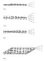
- the electrode layers may be formed as a single layer 2 and 3. However, as may be seen from Figure 2, the electrode layers may also be formed as a multilayer structure comprising the same number of layers on each side. As shown in Figure 2, each electrode comprises two layers 5,7 and 6,8. Each electrode may of course have more than two layers if desired.
- the anode layer and the cathode layer both comprise an electrolyte material, at least one metal and a catalyst material.
- the at least one metal is preferably selected from the group consisting of Ni, a FeCrMx alloy, and a NiCrMx alloy, wherein Mx is selected from the group consisting of Ni, Ti, Ce, Mn, Mo, W, Co, La, Y, Zr, Al, and mixtures thereof. More preferably, the at least one metal is a FeCrMx alloy.
- the finally obtained electrode structure comprises three independent percolating phases, namely electrolyte material, metal and porosity.
- the electrolyte material is preferably selected from the group consisting of doped zirconia, doped ceria, gallates and proton conducting electrolytes.
- the catalyst particles needed for the electrode function may also be preferably formed in a chemical reaction between a precursor added by impregnation and elements being exsolved from the metal phase or the electrolyte material in the backbone structure during use or during a specific heating cycle in controlled atmosphere.
- Mn, Ni or Co is supplied to the catalyst particles from the metal.
- the electrode layers advantageously comprise an electrolyte material, at least one metal and a catalyst material.
- the electrode layers comprising said electrolyte material thus provide ionic conductivity and, at the same time, provide good bonding to the electrolyte layer.
- the metal on the other hand provides electronic conductivity and increases the thermal expansion coefficient of the electrode layers. Furthermore, since the metal is part of the sintered electrode layers, there is no need of percolating the catalyst material in the final cell.
- the catalyst material may be formed as very fine particles during the impregnation step since the metal provides percolating electronic conductivity to the electrode layer.
- a disadvantageous coarsening of the catalyst particles can be efficiently reduced or avoided.
- less amount of catalyst is needed, further reducing the manufacturing costs.
- the electrolyte material of the thin solid oxide cell specifically comprises doped ceria.
- the anode layer and the cathode layer to comprise at least one metal.
- metal may be added if desired, depending on the application purpose.
- the above described thin solid oxide cell is obtainable by a method comprising the steps of:
- the first and second electrode layer and said electrolyte layer are manufactured independently, for example by tape-casting, and are subsequently laminated, i.e. by rolling, to form the thin solid oxide fuel cell.
- steps of tape casting the electrode layers and electrolyte layer being carried out by co-casting of the respective layers directly on top of each other. This can be done by tape casting including "wet on dry” casting and "wet on wet” casting. It is further preferred to employ wet on wet tape casting.
- the electrolyte layer of the thin reversible solid oxide fuel cell is a multilayer structure comprising at least two layers, as illustrated by layers 9 and 10 in Figure 3.
- the overall thickness of said multilayer structure is still about 2 to about 20 ⁇ m, more preferably of about 6 to about 18 ⁇ m, as mentioned above.
- the electrolyte layer may, for example, be formed from two layers each having a thickness of about 5 ⁇ m.
- the electrode layers may also be multilayer structures comprising at least two layers each, as illustrated by electrode layers 5,7 and 6,8 in Figure 2, having the same overall thickness of about 65 ⁇ m or less, more preferred of about 40 ⁇ m or less, respectively. More preferred is a multilayer structure wherein the at least two layers have a different thermal expansion coefficient (TEC). This may, for instance, be achieved by a different amount of metal in the respective layers.
- TEC thermal expansion coefficient
- the TEC of the outer electrode layer 7,8 is smaller than the TEC of the electrode layers 5,6 being in contact with the electrolyte layer 4.
- Electrolyte layer 4 has the lowest TEC.
- the cathode layer and the anode layer comprise two different layers each, as shown in Figure 2, wherein the respective layers directly in contact with the electrolyte layer have identical thermal expansion coefficient the value of which is larger than the thermal expansion coefficient of the electrolyte layer, and larger than the thermal expansion coefficient of the respective second layers of the electrodes. Furthermore, the thermal expansion coefficients of the respective second layers are also identical.
- each further layer has a thermal expansion coefficient being smaller than the one of the layer on the side closer to the electrolyte layer, while maintaining an overall symmetrical cell structure.
- the final cell structure is a symmetrical structure, with the electrolyte layer being sandwiched by the at least two electrode layers as described above, the respective layers having a smaller TEC than the two layers in contact with the electrolyte layer will be under compression during cooling. This is due to the outermost layer on each side of the electrolyte having a smaller thermal expansion coefficient, as compared to the inner layers. Consequently, the cell advantageously exhibits an improved stability, resulting in a longer cell life.
- the manufactured cell structure is profiled prior to sintering so as to obtain a patterned structure.
- Patterned structures include a ribbon structure or egg tray structure, as illustrated by Figure 4.
- the pattern may advantageously act as gas channels in the cell during later use. Said pattern contributes to the overall stiffness and handling strength of the cell.
- the profiling of the cell further increases the power/volume performance of the stack which is highly advantageous in certain applications.
- the respective interconnects separating the individual cells which are stacked in series may be flat foils and do not have to have a structure including said gas channels. This reduces the costs of the interconnector and makes the overall production method more cost effective.
- a combination of co-casting and laminating the layers may be employed.
- the respective electrode multilayer structures may be co-cast and then laminated to the electrolyte layer, which is preferred.
- the electrolyte layers may be co-cast and then laminated to the electrode layers.
- the electrode layers are impregnated with a catalyst or precursor thereof. This can be done by masking the first electrode layer, impregnating the unmasked second electrode layer, followed by demasking the first and masking the second, now impregnated electrode layer, then impregnating the second electrode layer, and finally demasking the first electrode layer.
- the catalyst material may be formed as very fine particles during the impregnation step since the metal provides electronic conductivity.
- a disadvantageous coarsening of the catalyst particles which otherwise occurs when sintering the cell, can be efficiently reduced or avoided.
- less amount of catalyst is needed, further reducing the manufacturing costs of the cell.
- the catalyst or precursor thereof for the impregnation of the first or second electrode layer which will function as the cathode layer is selected from the group consisting of manganites, ferrites, cobaltites and nickelates or mixtures thereof.
- Examples include lanthanum strontium manganate, lanthanide strontium iron cobalt oxide, (Gd 1x Ca x )Fe 1-y Co y O 3 , (La 1-x Sr x )MnO 3- ⁇ ), (Ln 1-x Sr x )MnO 3- ⁇ , (La 1-x Sr x ) Fe 1-y Co y O 3- ⁇ , (Ln 1-x Sr x )Fe 1-y Co y O 3- ⁇ , (Y 1-x Ca x )Fe 1-y Co y O 3- ⁇ , (Gd 1-x Sr x )Fe 1-y Co y O 3- ⁇ , (Gd 1-x Sr x )Fe 1-y Co y O 3- ⁇ , (Gd
- electrolyte materials such as doped zirconia or doped ceria may also be impregnated.
- the catalyst or precursor thereof for the impregnation of the first or second electrode layer which will function as the anode layer is selected from the group consisting of Ni, Fe x Ni 1-x alloys and a mixture of Ni and doped ceria/zirconia or a mixture of Cu and Cu and doped zirconia/ceria.
- the sintering step prior to impregnation is preferably carried out at a temperature of from about 900°C to about 1500°C, preferably from about 1000°C to about 1400°C.
- Additions may be added to the layer compositions if needed, such as pore formers, sintering additives, solvents and the like as is well known to the skilled person.
- the present invention is also directed to a thin and in principle unsupported separation membrane, comprising at least a porous anode layer, a membrane layer comprising a mixed conducting material and a porous cathode layer, wherein the anode layer and the cathode layer comprise the mixed conducting material and a catalyst material, and wherein the overall thickness of the thin separation membrane is about 150 ⁇ m or less.
- the thin separation membrane can be used as an oxygen separation membrane, especially for the production of oxygen or synthesis gas, in case the membrane is designed as an oxygen ion conductor.
- the membrane may, if instead based on a proton conducting material alternatively be used as a hydrogen separation membrane, especially for the production of high purity hydrogen for e.g. storage or use in a low-temperature fuel cell.
- the anode layer and the cathode layer comprise at least one metal.
- the at least one metal is the same as outlined in detail above for the SOC.
- the mixed conducting material is preferably selected from the group consisting of doped ceria, gallates and proton conducting electrolytes.
- the electrolyte being doped ceria.
- Preferred dopants for the doped ceria are Sm or Gd.
- the component comprising doped ceria as the mixed conducting material of the membrane layer and electrode layers is that said structure may be used as a high temperature oxygen separation membrane at temperatures of from about 550 to about 1000°C due to the increase of the electronic conductivity of the ceria.
- ceria exhibits mainly ionic conductivity, and thus said component can be used as a reversible SOFC at said temperatures instead.
- the membrane layer comprises doped ceria as the mixed conducting material.
- the anode layer and cathode layer comprise at least one metal when the membrane layer comprises doped ceria.
- the thin separation membrane is obtainable by a method comprising the steps of:
- Example 1 Manufacture of a thin solid oxide cell
- the first step comprises tape-casting of two layers (layer 1 - electrode precursor layer, and layer 2 - electrolyte layer).
- Suspensions for tape-casting are manufactured by means of ball milling of powders with polyvinyl pyrrolidone (PVP), polyvinyl butyral (PVB) and EtOH + MEK as additives. After control of particle size, the suspensions are tape-cast using a double doctor blade set-up and the tapes are subsequently dried.
- Layer 1 The suspension comprises SYSZ (scandia and yttria doped stabilized zirconia) and FeCr powder in a 1:1 volume ratio.
- the green thickness is about 40 ⁇ m.
- the sintered porosity of the layer is about 50%.
- Layer 2 The suspension is based on SYSZ powder with AI 2 O 3 as sintering additive.
- the green thickness of the foil is about 15 ⁇ m.
- the sintered density of the layer is >96 % of the theoretical density.
- the second step comprises the lamination of the above mentioned foils into a layered structure comprising an electrolyte layer (1) sandwiched between two electrode precursor layers (2, 3), as shown in Fig. 1.
- the lamination is performed by the use of heated rolls in a double roll set-up and takes place in one pass.
- the laminated tapes are cut into square pieces. This is done by knife punching resulting in sintered areas in the range of 12x12 to 30x30 cm 2 .
- the fourth step comprises sintering.
- the laminate is heated at with a temperature increase of about 50 °C/h to about 500 °C under flowing air. After 2 hours of soaking, the furnace is evacuated and H 2 introduced. After 3 hours soaking time, the furnace is heated to about 1200 °C with a temperature increase of 100 °C/h and left for 5 hours before cooling to room temperature.
- the fifth step is the impregnation of the cathode.
- the sintered cell is closed on one side.
- a nitrate solution of La, Sr, Co and Fe is vacuum infiltrated into the porous structure.
- the infiltration is performed six times with an intermediate heating step for decomposition of the nitrates.
- the resulting composition of the impregnated perovskite cathode is: (La 0.6 Sr 0.4 )(Co 0.2 Fe 0.8 )O 3- ⁇ .
- the anode is impregnated.
- the cathode impregnated side is closed.
- a nitrate solution of Ni, Ce and Gd is vacuum infiltrated into the porous structure.
- the infiltration is performed five times with an intermediate heating schedule between each infiltration for decomposition of the impregnated nitrates.
- the resulting composition of the impregnated anode part is 40 vol% Ni and 60 vol% (Ce 0.9 Gd 0.1 )O 2- ⁇ (after reduction of NiO).
- the so formed cell has a thickness of about 90 microns and is ready to be built into a stack of cells. No heat treatment prior to stacking is required.
- Example 2 Manufacture of a thin solid oxide cell
- the cell is produced as outlined above for Example 1, with the exception that in step five the cathode is impregnated.
- the sintered cell is closed on one side.
- a colloidal suspension of (La 0.6 Sr 0,4 )(Co 0.2 Fe 0.8 )O 3- ⁇ and (Ce 0.9 Sm 0.1 )O 2- ⁇ is vacuum infiltrated into the porous structure. The infiltration is performed six times with an intermediate heating step.
- the obtained cell has a thickness of about 95 microns and is ready to be built into a stack of cells. No heat treatment prior to stacking is required.
- Example 3 Manufacture of a thin solid oxide cell
- the manufacturing is carried out as described in Example 1 for steps one to four.
- the fifth step is the impregnation of the cathode.
- the sintered cell is closed on one side by a polymeric seal.
- a colloidal suspension of (La 0.75 Sr 0.25 )MnO 3- ⁇ is vacuum infiltrated into the porous structure. The infiltration is performed six times with an intermediate drying between each infiltration.
- the cell is completed as described in Example 1.
- the obtained cell has a thickness of about 100 microns and is ready to be built into a stack of cells. No heat treatment prior to stacking is required.
- Example 4 Manufacture of a thin solid oxide cell
- the first step comprises tape-casting of two layers (layer 1 - electrode precursor layer, and layer 2 - electrolyte layer).
- Suspensions for tape-casting are manufactured by means of ball milling of powders with polyvinyl pyrrolidone (PVP), polyvinyl butyral (PVB) and EtOH + MEK as additives. After control of particle size, the suspensions are tape-cast using a double doctor blade set-up and the tapes are subsequently dried.
- Layer 1 The suspension is based on (Ce 0.9 Gd 0.1 )O 2- ⁇ with FeCr metal powder using charcoal as a pore-former.
- the green thickness is about 40 ⁇ m.
- the sintered porosity of the layer is about 50%.
- Layer 2 The suspension is based on (Ce 0.9 Gd 0.1 )O 2- ⁇ powder.
- the green thickness of the foil is about 12 ⁇ m.
- the sintered density of the layer is >96 % of the theoretical density.
- the second step comprises the lamination of the above mentioned foils into a layered structure comprising an electrolyte layer (1) sandwiched between two electrode precursor layers (2, 3), as shown in Fig. 1.
- the lamination is performed by the use of heated rolls in a double roll set-up and takes place in one pass.
- the laminated tapes are cut into square pieces. This is done by knife punching resulting in sintered areas in the range of 12x12 to 30x30 cm 2 .
- the fourth step comprises sintering.
- the laminate is heated at a temperature increase of about 50 °C/h to about 500 °C under flowing air. After 2 hours of soaking, the furnace is evacuated and H 2 introduced. After 3 hours soaking time, the furnace is heated to about 1200 °C with a temperature increase of 100 °C/h and left for 5 hours before cooling to room temperature.
- the fifth step is the impregnation of the cathode.
- the sintered cell is closed on one side.
- a nitrate solution of La, Sr, Co and Fe is vacuum infiltrated into the porous structure.
- the infiltration is performed six times with an intermediate heating step for decomposition of the nitrates.
- the resulting composition of the impregnated perovskite cathode is: (La 0.6 Sr 0.4 )(CO 0.2 Fe 0.8 )O 3- ⁇ .
- the anode is impregnated.
- the cathode impregnated side is closed.
- a nitrate solution of Ni, Ce and Gd is vacuum infiltrated into the porous structure.
- the infiltration is performed five times with an intermediate heating schedule between each infiltration for decomposition of the impregnated nitrates.
- the resulting composition of the impregnated anode part is 40 vol% Ni and 60 vol% (Ce 0.9 Gd 0.1 )O 2- ⁇ (after reduction of NiO).
- the so formed cell is about 100 microns thick and ready to be build into a stack of cells. No heat treatment prior to stacking is required.
- Example 5 Manufacture of a thin solid oxide cell having a very thin electrolyte layer
- the first step comprises tape-casting of two layers (layer 1 - electrode precursor layer, and layer 2 - electrolyte layer).
- Suspensions for tape-casting are manufactured by means of ball milling of powders with polyvinyl pyrrolidone (PVP), polyvinyl butyral (PVB) and EtOH + MEK as additives. After control of particle size, the suspensions are tape-cast using a double doctor blade set-up and the tapes are subsequently dried.
- Layer 1 The suspension comprises SYSZ and FeCr powder in a 1:1 volume ratio.
- the green thickness is about 40 ⁇ m.
- the sintered porosity of the layer is about 50%.
- Layer 2 The suspension is based on Zr 0.78 Sc 0.2 Y 0.02 O 2- ⁇ powder.
- the green thickness of the foil is about 5 ⁇ m.
- the sintered density of the layer is >96 % of the theoretical density.
- the cell is completed as described in Example 1.
- the so formed cell is about 80 microns thick and ready to be build into a stack of cells. No heat treatment prior to stacking is required.
- Example 6 Manufacture of a thin solid oxide cell having multi layer electrodes
- the first step comprises tape-casting of three layers; two metal containing electrode precursor layers (layer 1 and 2) and one electrolyte layer (layer 3).
- Suspensions for tape-casting are manufactured by means of ball milling of powders with polyvinyl pyrrolidone (PVP), polyvinyl butyral (PVB) and EtOH + MEK as additives.
- PVP polyvinyl pyrrolidone
- PVB polyvinyl butyral
- EtOH + MEK EtOH + MEK
- Layer 1 The suspension comprises SYSZ and FeCr powder in a 1:1 volume ratio. 20 vol% graphite is used as pore former. The green thickness is about 30 ⁇ m. The sintered porosity of the layer is about 50%.
- Layer 2 The suspension is based on SYSZ and FeCr powder in a 1:1.1 volume ratio. 15% graphite is used as a pore-former. The green thickness of the foil is about 25 ⁇ m. The sintered porosity of the layer is about 50%.
- Layer 3 The suspension is based on SYSZ powder.
- the green thickness of the foil is about 10 ⁇ m.
- the sintered density of the layer is >96 % of the theoretical density.
- the second step comprises the lamination of the above mentioned foils into a layered structure comprising an electrolyte layer (sandwiched between two electrode precursor layers on each side in the order Layer 1 - Layer 2 - Layer 3 - Layer 2 - Layer 1 .
- This layer structure corresponds to layers 4 to 8 as shown in Fig. 2.
- the lamination is performed by the use of heated rolls in a double roll set-up and takes place in one pass.
- the laminated tapes are cut into square pieces. This is done by knife punching of samples with an area of about 600 cm 2 .
- the cell is completed as described in Example 1.
- the obtained cell is about 120 microns thick and ready to be build into a stack of cells. No heat treatment prior to stacking is required.
- Example 7 Manufacture of a thin solid oxide cell having a multilayer electrolyte
- the first step comprises tape-casting of two layers (layer 1 - electrode precursor layer, and layer 2 - electrolyte layer).
- Suspensions for tape-casting are manufactured by means of ball milling of powders with polyvinyl pyrrolidone (PVP), polyvinyl butyral (PVB) and EtOH + MEK as additives. After control of particle size, the suspensions are tape-cast using a double doctor blade set-up and the tapes are subsequently dried.
- Layer 1 The suspension comprises SYSZ and FeCr powder in a 1:1 volume ratio.
- the green thickness is about 40 ⁇ m.
- the sintered porosity of the layer is about 50%.
- Layer 2 The suspension is based on SYSZ powder.
- the green thickness of the foil is about 3 ⁇ m (sintered thickness is about 2 ⁇ m).
- the sintered density of the layer is >96 % of the theoretical density.
- the second step comprises the lamination of the above mentioned foils into a layered structure comprising two electrolyte layers (9, 10) sandwiched between two electrode precursor layers (11, 12), as shown in Fig. 3.
- the lamination is performed by the use of heated rolls in a double roll set-up and takes place in one pass.
- the laminated tapes are cut into square pieces. This is done by knife punching resulting in sintered areas in the range of 12x12 to 30x30 cm 2 .
- the fourth step comprises sintering.
- the laminate is heated at an increase of about 50 °C/h to about 500 °C under flowing air. After 2 hours of soaking, the furnace is evacuated and H 2 introduced. After 3 hours soaking time, the furnace is heated to about 1200 °C with a temperature increase of 100 °C/h and left for 5 hours before cooling to room temperature.
- the fifth step is the impregnation of the cathode.
- the sintered cell is closed on one side by a rubber seal.
- a nitrate solution of Gd, Sr, Co and Fe is vacuum infiltrated into the porous structure.
- the infiltration is performed six times with an intermediate heating step for decomposition of the nitrates.
- the resulting composition of the impregnated perovskite cathode is: (Gd 0.6 Sr 0,4 )(CO 0.2 Fe 0.8 )O 3- ⁇ .
- the anode is impregnated.
- the cathode impregnated side is closed by a rubber seal.
- a nitrate solution of Cu, Ni, Ce and Gd is vacuum infiltrated into the porous structure.
- the infiltration is performed six times with an intermediate heating schedule between each infiltration for decomposition of the impregnated nitrates.
- the resulting composition of the impregnated anode part is 4 vol% Cu, 38 vol% Ni and 58 vol% (Ce 0.9 Gd 0.1 )O 2- ⁇ (after reduction of NiO).
- the obtained cell is about 100 microns thick and ready to be build into a stack of cells. No heat treatment prior to stacking is required.
- Example 8 Manufacture of a thin solid oxide cell with a patterned profiled structure
- the laminated tapes are cut into pieces. This is done by knife punching resulting in sintered areas in the range up to 40x40 cm 2 .
- the laminated structures are given an egg tray pattern profiled structure by pressing, electrolyte layer (13) and two electrode precursor layers (14,15), as shown in Fig. 4.
- the fifth step comprises sintering.
- the laminate is heated at an increase of about 50 °C/h to about 500 °C under flowing air. After 2 hours of soaking, the furnace is evacuated and H 2 introduced. After 3 hours soaking time, the furnace is heated to about 1200 °C with a temperature increase of 100 °C/h and left for 5 hours before cooling to room temperature.
- the sixth step is the impregnation of the cathode.
- the sintered cell is closed on one side by a rubber seal.
- a nitrate solution of Gd, Sr, Co and Fe is vacuum infiltrated into the porous structure. The infiltration is performed six times with an intermediate heating step for decomposition of the nitrates.
- the resulting composition of the impregnated perovskite cathode is: (Gd 0.6 Sr 0,4 )(Co 0.2 Fe 0.8 )O 3- ⁇ .
- the anode is impregnated.
- the cathode impregnated side is closed by a rubber seal.
- a nitrate solution of Ni, Ce and Gd is vacuum infiltrated into the porous structure.
- the infiltration is performed seven times with an intermediate heating schedule between each infiltration for decomposition of the impregnated nitrates.
- the resulting composition of the impregnated anode part is 50 vol% Ni and 50 vol% (Ce 0.9 Gd 0.1 )O 2- ⁇ (after reduction of NiO).
- the obtained cell is about 95 microns thick and ready to be build into a stack of cells. No heat treatment prior to stacking is required.
- Example 9 Manufacture of a ceria - low T SOFC, high T oxygen separation membrane
- the first step comprises tape-casting of two layers (layer 1 - electrode precursor layer, and layer 2 - electrolyte layer).
- Suspensions for tape-casting are manufactured by means of ball milling of powders with polyvinyl pyrrolidone (PVP), polyvinyl butyral (PVB) and EtOH + MEK as additives. After control of particle size, the suspensions are tape-cast using a double doctor blade set-up and the tapes are subsequently dried.
- Layer 1 The suspension comprises pre-calcined (Ce 0.9 Gd 0.1 )O 2- ⁇ and 10 vol% charcoal as a pore-former.
- the green thickness is about 40 ⁇ m.
- the sintered porosity of the layer is about 50%.
- Layer 2 The suspension is based on (Ce 0.9 Gd 0.1 )O 2- ⁇ powder.
- the green thickness of the foil is about 12 ⁇ m.
- the sintered density of the layer is >96 % of the theoretical density.
- Step two to four are carried out as described in Example 1.
- the fifth step is the impregnation of the cathode.
- the sintered cell is closed on one side by a rubber seal.
- a nitrate solution of La, Sr, Co and Fe is vacuum infiltrated into the porous structure.
- the infiltration is performed six times with an intermediate heating step for decomposition of the nitrates.
- the resulting composition of the impregnated perovskite cathode is: (La 0.6 Sr 0.4 )(Co 0.2 Fe 0.8 )O 3- ⁇ .
- the anode is impregnated.
- the cathode impregnated side is closed by a rubber seal.
- a colloidal suspension of NiO and (Sr 0.8 La 0.2 )(Nb 0.1 Ti 0.9 )O 3- ⁇ is vacuum infiltrated into the porous structure. The infiltration is performed five times with an intermediate drying between each infiltration. The volume ratio of NiO:SLNT is 1:10.
- the obtained membrane is about 100 microns thick and ready to be build into a stack of cells. No heat treatment prior to stacking is required.
- Example 10 Manufacture of a ceria - low T SOFC, high T oxygen separation membrane
- the membrane was obtained as described in Example 9, with the exception that a mixture of (Ce 0.9 Gd 0.1 )O 2- ⁇ and FeCr powder in a 1:1 volume is used in layer 1.
- Example 11 Manufacture of a ceria - low T SOFC, high T oxygen separation membrane
- the first step comprises co-casting of a three layered structure (layer 1 and 3 - electrode precursor layer, and layer 2 - electrolyte layer) with intermediate drying after tape-casting of each layer.
- Suspensions for tape-casting are manufactured by means of ball milling of powders with polyvinyl pyrrolidone (PVP), polyvinyl butyral (PVB) and EtOH + MEK as additives. After control of particle size, the suspensions are tape-cast using a double doctor blade set-up as described below and the cast is subsequently dried.
- Suspension 1, Layer 1 and 3 The suspension comprises pre-calcined (Ce 0.9 Gd 0.1 )O 2- ⁇ and 10 vol% charcoal as a pore-former.
- the green thickness is about 40 ⁇ m.
- the sintered porosity of the layer is about 50%.
- Suspension 2 Layer 2: The suspension is based on (Ce 0.9 Gd 0.1 )O 2- ⁇ with Co 3 O 4 as sintering additive The green thickness of the foil is about 12 ⁇ m. The sintered density of the layer is >96 % of the theoretical density.
- Layer 1 is tape-cast onto a polymeric foil. After drying, Layer 2 is tape-cast directly onto Layer 1, and after a subsequent drying Layer 3 (Suspension 1) is tape-cast directly onto the two layered structure comprising Layer 1 of Layer 2.
- Layer 3 (Suspension 1) is tape-cast directly onto the two layered structure comprising Layer 1 of Layer 2.
- the co-cast tapes are cut into square pieces. This is done by knife punching resulting in sintered areas in the range of 200-600 cm 2 .
- the third step comprises sintering.
- the laminate is heated at an increase of about 50 °C/h to about 500 °C under flowing air. After 2 hours of soaking, the furnace is to about 1150 °C with a temperature increase of 100 °C/h and left for 5 hours before cooling to room temperature.
- the fifth step is the impregnation of the cathode.
- the sintered cell is closed on one side.
- a nitrate solution of La, Sr and Co is vacuum infiltrated into the porous structure.
- the infiltration is performed six times with an intermediate heating step for decomposition of the nitrates.
- the resulting composition of the impregnated perovskite cathode is: (La 0.6 Sr 0,4 )CoO 3- ⁇ .
- the anode is impregnated.
- the cathode impregnated side is closed.
- a nitrate solution of Ni, Ce and Gd is vacuum infiltrated into the porous structure.
- the infiltration is performed five times with an intermediate heating schedule between each infiltration for decomposition of the impregnated nitrates.
- the resulting composition of the impregnated anode part is 50 vol% Ni and 50 vol% (Ce 0.9 Gd 0.1 )O 2- ⁇ (after reduction of NiO).
- the obtained membrane is about 100 microns thick and ready to be build into a stack of cells. No heat treatment prior to stacking is required.
- Example 12 Manufacture of a (ceria - low T SOFC, high T oxygen separation membrane
- the first step comprises co-casting of a three layered structure (layer 1 and 3 - electrode precursor layer, and layer 2 - electrolyte layer) without intermediate drying.
- Suspensions for tape-casting are manufactured by means of ball milling of powders with polyvinyl pyrrolidone (PVP), polyvinyl butyral (PVB) and EtOH + MEK as additives. After control of particle size, the suspensions are tape-cast using a double doctor blade set-up as described below and the cast is subsequently dried.
- Suspension 1, Layer 1 and 3 The suspension comprises pre-calcined (Ce 0.9 Gd 0.1 )O 2- ⁇ and 10 vol% charcoal as a pore-former.
- the green thickness is about 40 ⁇ m.
- the sintered porosity of the layer is about 50% with.
- Suspension 2 Layer 2: The suspension is based on (Ce 0.9 Gd 0.1 )O 2- ⁇ .
- the green thickness of the foil is about 12 ⁇ m.
- the sintered density of the layer is >96 % of the theoretical density.
- the co-cast tapes are cut into square pieces. This is done by knife punching resulting in sintered areas in the range of 200-600 cm 2 .
- the third step comprises sintering.
- the laminate is heated at an increase of about 50 °C/h to about 500 °C under flowing air. After 2 hours of soaking, the furnace is heated to about 1150 °C with a temperature increase of 100 °C/h and left for 5 hours before cooling to room temperature.
- the fifth step is the impregnation of the cathode.
- the sintered cell is closed on one side.
- a nitrate solution of La, Sr and Co is vacuum infiltrated into the porous structure.
- the infiltration is performed six times with an intermediate heating step for decomposition of the nitrates.
- the resulting composition of the impregnated perovskite cathode is: (La 0.6 Sr 0,4 )CoO 3- ⁇ .
- the anode is impregnated.
- the cathode impregnated side is closed.
- a nitrate solution of Ni, Ce and Gd is vacuum infiltrated into the porous structure.
- the infiltration is performed five times with an intermediate heating schedule between each infiltration for decomposition of the impregnated nitrates.
- the resulting composition of the impregnated anode part is 50 vol% Ni and 50 vol% (Ce 0.9 Gd 0.1 )O 2- ⁇ (after reduction of NiO).
- the obtained membrane is about 100 microns thick and ready to be build into a stack of cells. No heat treatment prior to stacking is required.
- the first step comprises tape-casting of two layers (layer 1 - electrode precursor layer, and layer 2 - electrolyte layer).
- Suspensions for tape-casting are manufactured by means of ball milling of powders with polyvinyl pyrrolidone (PVP), polyvinyl butyral (PVB) and EtOH + MEK as additives. After control of particle size, the suspensions are tape-cast using a double doctor blade set-up and the tapes are subsequently dried.
- the green thickness is about 40 ⁇ m.
- the sintered porosity of the layer is about 50%.
- Layer 2 The suspension is based on (La 0.85 Sr 0.15 Ga 0.8 Mg 0.2 O 3 ). powder using charcoal as a pore-former. The green thickness of the foil is about 12 ⁇ m. The sintered density of the layer is >96 % of the theoretical density.
- the second step comprises the lamination of the above mentioned foils into a layered structure comprising an electrolyte layer (1) sandwiched between two electrode precursor (2, 3) layers, as shown in Fig. 1.
- the lamination is performed by the use of heated rolls in a double roll set-up and takes place in one pass.
- the laminated tapes are cut into square pieces. This is done by knife punching resulting in sintered areas in the range of 12x12 to 30x30 cm 2 .
- the fourth step comprises sintering.
- the laminate is heated at an increase of about 50 °C/h to about 500 °C under flowing air. After 2 hours of soaking, the furnace is to about (1400 °C) with a temperature increase of 100 °C/h and left for 4 hours before cooling to room temperature.
- the fifth step is the impregnation of the cathode.
- the sintered cell is closed on one side by a rubber seal.
- a nitrate solution of La, Sr, Fe, Co is vacuum infiltrated into the porous structure.
- the infiltration is performed six times with an intermediate heating step for decomposition of the nitrates.
- the resulting composition of the impregnated cathode is: (La 0.6 Sr 0,4 )(Co 0.2 Fe 0.8 )O 3- ⁇ .
- the anode is impregnated.
- the cathode impregnated side is closed by a rubber seal.
- a nitrate solution of La, Sr, Mn and Cr is vacuum infiltrated into the porous structure. The infiltration is performed five times with an intermediate heating schedule between each infiltration for decomposition of the impregnated nitrates.
- the obtained cell is about 100 microns thick and ready to be build into a stack of cells s. No heat treatment prior to stacking is required.
- Example 14 Manufacture of a thin solid oxide cell (Proton conductor)
- the first step comprises tape-casting of two layers (layer 1 - electrode precursor layer, and layer 2 - electrolyte layer).
- Suspensions for tape-casting are manufactured by means of ball milling of powders with polyvinyl pyrrolidone (PVP), polyvinyl butyral (PVB) and EtOH + MEK as additives. After control of particle size, the suspensions are tape-cast using a double doctor blade set-up and the tapes are subsequently dried.
- Layer 1 The suspension comprises pre-calcined SrCe 0.95 Yb 0.05 O 3- ⁇ and 20 vol% graphite as a pore-former.
- the green thickness is about 40 ⁇ m.
- the sintered porosity of the layer is about 50%.
- Layer 2 The suspension is based on SrCe 0.95 Yb 0.05 O 3- ⁇ powder
- the green thickness of the foil is about 15 ⁇ m.
- the sintered density of the layer is >96 % of the theoretical density.
- the second step comprises the lamination of the above mentioned foils into a layered structure comprising an electrolyte layer (1) sandwiched between two electrode precursor layers (2, 3), as shown in FIG 1.
- the lamination is performed by the use of heated rolls in a double roll set-up and takes place in one pass.
- the laminated tapes are cut into square pieces. This is done by knife punching resulting in sintered areas in the range of 12x12 to 30x30 cm 2 .
- the fourth step comprises sintering.
- the laminate is heated at an increase of about 50 °C/h to about 500 °C under flowing air. After 2 hours of soaking, the furnace is to about (1600 °C) with a temperature increase of 100 °C/h and left for 4 hours before cooling to room temperature.
- the fifth step is the impregnation of the cathode.
- the sintered cell is closed on one side by a rubber seal.
- a colloidal suspension of Pd or Pt is vacuum infiltrated into the porous structure. The infiltration is performed six times with an intermediate heating step
- the anode is impregnated.
- the cathode impregnated side is closed by a rubber seal.
- a colloidal suspension of Pd or Pt is vacuum infiltrated into the porous structure. The infiltration is performed six times with an intermediate heating step.
- the obtained cell is about 100 microns thick and ready to be build into a stack of cells. No heat treatment prior to stacking is required.
- Example 15 Manufacture of a thin proton membrane cell (Proton membrane)
- the first step comprises tape-casting of two layers (layer 1 - electrode precursor layer, and layer 2 - electrolyte layer).
- Suspensions for tape-casting are manufactured by means of ball milling of powders with polyvinyl pyrrolidone (PVP), polyvinyl butyral (PVB) and EtOH + MEK as additives. After control of particle size, the suspensions are tape-cast using a double doctor blade set-up and the tapes are subsequently dried.
- Layer 1 The suspension comprises Sr-zirconate and Fe 2 Cr powder in a 1:1 volume ratio.
- the green thickness is about 40 ⁇ m.
- the sintered porosity of the layer is about 50% with a pore size in the range of 1-2 ⁇ m.
- Layer 2 The suspension is based on Sr-zirconate powder.
- the green thickness of the foil is about 15 ⁇ m.
- the sintered density of the layer is >96 % of the theoretical density.
- the second step comprises the lamination of the above mentioned foils into a layered structure comprising an electrolyte layer (1) sandwiched between two electrode precursor layers (2, 3), as shown in Fig. 1.
- the lamination is performed by the use of heated rolls in a double roll set-up and takes place in one pass.
- the laminated tapes are cut into square pieces. This is done by knife punching resulting in sintered areas in the range of 200-600 cm 2 .
- the fourth step comprises sintering.
- the laminate is heated at an increase of about 50 °C/h to about 500 °C under flowing air. After 2 hours of soaking, the furnace is evacuated and H 2 introduced. After 3 hours soaking time, the furnace is heated to about 1300 °C with a temperature increase of 100 °C/h and left for 5 hours before cooling to room temperature.
- the fifth step is the impregnation of the electrodes.
- a colloidal suspension of Pd or Pd-Ag alloy is vacuum infiltrated into the porous structures.
- the infiltration is performed five times with an intermediate heating schedule between each infiltration.
- the so formed membrane is about 90 microns thick and ready to be built into a stack of cells. No heat treatment prior to stacking is required.
- the present invention provides a thin, preferably reversible and in principle unsupported solid oxide cell, particularly solid oxide fuel cell, which is very thin, i.e. has an overall thickness of about 150 ⁇ m or less. Due to the very thin cell, less material is needed for a given rated power, reducing the manufacturing costs of the cell.
- the electrode layers advantageously comprise an electrolyte material, in one embodiment at least one metal and a catalyst material. Since metal is in this case part of the sintered electrode layers, electronic conductivity is provided without the need of percolating the catalyst material.
- the electronic conductivity of the electrode layers is higher as compared to electrode layers which do not contain metal and are only impregnated after the sintering, leading to an overall improved performance of the cell.
- the catalyst material may be formed as very fine particles during the impregnation step since the metal provides electronic conductivity.
- a disadvantageous coarsening of the catalyst particles during sintering of the cell can be efficiently reduced or avoided. Additionally, less catalyst is needed, further reducing the manufacturing costs.
- redox-stability of the anode may be obtained as the nickel particles not necessarily constitute a percolating network.
- the electrode layer comprises doped ceria
- the electrode layers advantageously comprise an electrolyte material and a catalyst material.
Landscapes
- Chemical & Material Sciences (AREA)
- Engineering & Computer Science (AREA)
- Chemical Kinetics & Catalysis (AREA)
- General Chemical & Material Sciences (AREA)
- Electrochemistry (AREA)
- Manufacturing & Machinery (AREA)
- Materials Engineering (AREA)
- Inorganic Chemistry (AREA)
- Sustainable Energy (AREA)
- Sustainable Development (AREA)
- Life Sciences & Earth Sciences (AREA)
- Ceramic Engineering (AREA)
- Composite Materials (AREA)
- Physics & Mathematics (AREA)
- Thermal Sciences (AREA)
- Inert Electrodes (AREA)
- Fuel Cell (AREA)
- Separation Using Semi-Permeable Membranes (AREA)
Priority Applications (14)
| Application Number | Priority Date | Filing Date | Title |
|---|---|---|---|
| EP06024338A EP1928049A1 (fr) | 2006-11-23 | 2006-11-23 | Pile à combustible à oxyde solide mince |
| CA002669811A CA2669811A1 (fr) | 2006-11-23 | 2007-11-23 | Pile a oxyde solide mince |
| CN201410088244.XA CN103861470A (zh) | 2006-11-23 | 2007-11-23 | 薄层分离膜及其制备方法 |
| EP07846794A EP2084772A2 (fr) | 2006-11-23 | 2007-11-23 | Pile à oxyde solide mince |
| CN200780043660.6A CN101563805B (zh) | 2006-11-23 | 2007-11-23 | 薄层固体氧化物电池 |
| JP2009537554A JP5219298B2 (ja) | 2006-11-23 | 2007-11-23 | 薄い固体酸化物電池 |
| AU2007323291A AU2007323291B2 (en) | 2006-11-23 | 2007-11-23 | Thin solid oxide cell |
| US12/515,816 US9496576B2 (en) | 2006-11-23 | 2007-11-23 | Thin solid oxide cell |
| RU2009119261/07A RU2427945C2 (ru) | 2006-11-23 | 2007-11-23 | Тонкослойный твердооксидный элемент |
| KR1020097012019A KR101172362B1 (ko) | 2006-11-23 | 2007-11-23 | 얇은 고체 산화물 전지 |
| CA2797177A CA2797177A1 (fr) | 2006-11-23 | 2007-11-23 | Pile a oxyde solide mince |
| PCT/EP2007/010194 WO2008061782A2 (fr) | 2006-11-23 | 2007-11-23 | Pile à oxyde solide mince |
| EP13005452.1A EP2701227A1 (fr) | 2006-11-23 | 2007-11-23 | Pile à combustible à oxyde solide mince |
| NO20091876A NO20091876L (no) | 2006-11-23 | 2009-05-13 | Tynn fast oksidcelle |
Applications Claiming Priority (1)
| Application Number | Priority Date | Filing Date | Title |
|---|---|---|---|
| EP06024338A EP1928049A1 (fr) | 2006-11-23 | 2006-11-23 | Pile à combustible à oxyde solide mince |
Publications (1)
| Publication Number | Publication Date |
|---|---|
| EP1928049A1 true EP1928049A1 (fr) | 2008-06-04 |
Family
ID=37714681
Family Applications (3)
| Application Number | Title | Priority Date | Filing Date |
|---|---|---|---|
| EP06024338A Withdrawn EP1928049A1 (fr) | 2006-11-23 | 2006-11-23 | Pile à combustible à oxyde solide mince |
| EP07846794A Withdrawn EP2084772A2 (fr) | 2006-11-23 | 2007-11-23 | Pile à oxyde solide mince |
| EP13005452.1A Withdrawn EP2701227A1 (fr) | 2006-11-23 | 2007-11-23 | Pile à combustible à oxyde solide mince |
Family Applications After (2)
| Application Number | Title | Priority Date | Filing Date |
|---|---|---|---|
| EP07846794A Withdrawn EP2084772A2 (fr) | 2006-11-23 | 2007-11-23 | Pile à oxyde solide mince |
| EP13005452.1A Withdrawn EP2701227A1 (fr) | 2006-11-23 | 2007-11-23 | Pile à combustible à oxyde solide mince |
Country Status (10)
| Country | Link |
|---|---|
| US (1) | US9496576B2 (fr) |
| EP (3) | EP1928049A1 (fr) |
| JP (1) | JP5219298B2 (fr) |
| KR (1) | KR101172362B1 (fr) |
| CN (2) | CN103861470A (fr) |
| AU (1) | AU2007323291B2 (fr) |
| CA (2) | CA2797177A1 (fr) |
| NO (1) | NO20091876L (fr) |
| RU (1) | RU2427945C2 (fr) |
| WO (1) | WO2008061782A2 (fr) |
Cited By (9)
| Publication number | Priority date | Publication date | Assignee | Title |
|---|---|---|---|---|
| EP2103582A1 (fr) * | 2008-03-18 | 2009-09-23 | Technical University of Denmark | Procédé de production d'une structure multicouche |
| WO2009115319A1 (fr) * | 2008-03-18 | 2009-09-24 | Technical University Of Denmark | Pile à combustible à oxyde solide entièrement en céramique |
| EP2194597A1 (fr) | 2008-12-03 | 2010-06-09 | Technical University of Denmark | Cellule d'oxyde solide et pile de cellules d'oxyde solide |
| EP2338201A2 (fr) * | 2008-10-14 | 2011-06-29 | University of Florida Research Foundation, Inc. | Conception et matériaux avancés pour sofc à basse température |
| WO2015059166A1 (fr) * | 2013-10-22 | 2015-04-30 | Danmarks Tekniske Universitet | Corps précurseur en forme de demi-pile plane |
| WO2015110598A1 (fr) * | 2014-01-24 | 2015-07-30 | Danmarks Tekniske Universitet | Membrane de transport d'oxygène |
| EP2960977A1 (fr) * | 2014-06-27 | 2015-12-30 | Haldor Topsøe A/S | Fluage de support d'anode |
| EP2641291A4 (fr) * | 2010-11-16 | 2016-04-27 | Saint Gobain Ceramics | Cellules uniques sensiblement plates pour empilements de piles à combustible à oxyde solide |
| US9496576B2 (en) | 2006-11-23 | 2016-11-15 | Technical University Of Denmark | Thin solid oxide cell |
Families Citing this family (39)
| Publication number | Priority date | Publication date | Assignee | Title |
|---|---|---|---|---|
| JP5383232B2 (ja) * | 2009-01-30 | 2014-01-08 | 三菱重工業株式会社 | 固体電解質型燃料電池の発電膜及びこれを備える固体電解質型燃料電池 |
| KR101177621B1 (ko) * | 2010-06-25 | 2012-08-27 | 한국생산기술연구원 | 고체산화물 연료전지 단위셀의 제조방법 |
| US9642192B2 (en) * | 2011-08-04 | 2017-05-02 | Fuelcell Energy, Inc. | Method and manufacturing assembly for sintering fuel cell electrodes and impregnating porous electrodes with electrolyte powders by induction heating for mass production |
| US20140255736A1 (en) * | 2011-10-12 | 2014-09-11 | Toyota Jidosha Kabushiki Kaisha | Non-aqueous electrolyte secondary battery |
| CN102347495B (zh) * | 2011-10-19 | 2014-01-08 | 华北电力大学 | 固体氧化物燃料电池结构及其制备方法 |
| US20130316264A1 (en) * | 2012-05-24 | 2013-11-28 | Phillips 66 Company | Functionally layered electrolyte for solid oxide fuel cells |
| CN103872366B (zh) * | 2012-12-12 | 2016-12-07 | 中国科学院上海硅酸盐研究所 | 一种金属支撑固体氧化物燃料电池及其制备方法 |
| RU2522188C1 (ru) * | 2013-03-26 | 2014-07-10 | Федеральное государственное бюджетное учреждение науки Институт высокотемпературной электрохимии Уральского отделения Российской Академии наук | Способ получения двухслойного несущего катода для твердооксидных топливных элементов |
| WO2015054024A1 (fr) | 2013-10-08 | 2015-04-16 | Phillips 66 Company | Modification en phase gazeuse de piles à combustibles à oxydes solides |
| US9660273B2 (en) | 2013-10-08 | 2017-05-23 | Phillips 66 Company | Liquid phase modification of solid oxide fuel cells |
| US10418657B2 (en) | 2013-10-08 | 2019-09-17 | Phillips 66 Company | Formation of solid oxide fuel cells by spraying |
| US9574274B2 (en) * | 2014-04-21 | 2017-02-21 | University Of South Carolina | Partial oxidation of methane (POM) assisted solid oxide co-electrolysis |
| CN105226295B (zh) * | 2015-09-10 | 2019-05-03 | 江西赛瓷材料有限公司 | 一种基于空气制氧的电解质膜以及制氧方法 |
| US20180019494A1 (en) * | 2016-07-12 | 2018-01-18 | Lg Fuel Cell Systems Inc. | Regeneration of fuel cell electrodes |
| KR101872475B1 (ko) | 2016-07-20 | 2018-06-28 | 한국과학기술연구원 | 전해질용 소결체의 제조방법 및 이를 이용한 연료전지용 전해질 |
| CN106654362B (zh) * | 2016-12-07 | 2019-07-19 | 珠海光宇电池有限公司 | 复合固态电解质膜、制备方法及锂离子电池 |
| EP3757254A1 (fr) * | 2017-04-19 | 2020-12-30 | Ph Matter, LLC | Procédé d'utilisation d'une cellule électrochimique |
| JP6924391B2 (ja) * | 2017-05-25 | 2021-08-25 | 日産自動車株式会社 | 燃料電池セル |
| KR101992635B1 (ko) * | 2017-12-28 | 2019-06-25 | 한국에너지기술연구원 | 이산화탄소가 포함된 바이오가스로부터 합성가스 생산을 위한 soec와 rwgs를 결합한 촉매 전극 반응기 |
| CN108242554B (zh) * | 2018-01-10 | 2020-07-17 | 郑州大学 | 一种铈酸钡基电解质材料及其制备方法和应用 |
| KR101879152B1 (ko) * | 2018-01-18 | 2018-07-16 | 포항공과대학교 산학협력단 | 산화 전극, 이의 제조 방법, 및 이를 포함하는 전기 분해 장치 |
| US11767600B2 (en) * | 2018-11-06 | 2023-09-26 | Utility Global, Inc. | Hydrogen production system |
| US11761100B2 (en) * | 2018-11-06 | 2023-09-19 | Utility Global, Inc. | Electrochemical device and method of making |
| CN109742414A (zh) * | 2019-01-09 | 2019-05-10 | 渤海大学 | 一种中温固体氧化物燃料电池阴极材料及其制备方法与应用 |
| CN109755615B (zh) * | 2019-01-24 | 2021-05-28 | 深圳市致远动力科技有限公司 | 具有三维微纳结构的全固态薄膜燃料电池的制备方法 |
| CN110098434B (zh) * | 2019-04-09 | 2021-04-27 | 中国科学院合肥物质科学研究院 | 全固态锂电池中电极-电解质双层平整块材及其制备方法 |
| DE102019129070A1 (de) | 2019-10-28 | 2021-04-29 | Forschungszentrum Jülich GmbH | Elektrodenmaterial, Verfahren zu dessen Herstellung und dessen Verwendung |
| CN110828669A (zh) * | 2019-11-15 | 2020-02-21 | 中南大学 | 一种低温介孔碳基钙钛矿太阳能电池及其制备方法 |
| CN111416138A (zh) * | 2020-03-12 | 2020-07-14 | 西安交通大学 | 一种质子陶瓷膜燃料电池及其制备方法 |
| RU2735327C1 (ru) * | 2020-05-12 | 2020-10-30 | Федеральное государственное бюджетное учреждение науки Институт физики твердого тела Российской академии наук (ИФТТ РАН) | Способ изготовления двухслойной анодной подложки с тонкопленочным электролитом для твердооксидного топливного элемента |
| RU2766871C1 (ru) * | 2021-05-18 | 2022-03-16 | Федеральное государственное бюджетное учреждение науки Институт электрофизики Уральского отделения Российской академии наук | Структура активной части элементов твердооксидных устройств с плотным электродным текстурированным слоем (варианты) |
| CN113564625A (zh) * | 2021-09-14 | 2021-10-29 | 北京思伟特新能源科技有限公司 | 质子传导型固体氧化物电解池及其制备方法 |
| CN113667998A (zh) * | 2021-09-15 | 2021-11-19 | 北京思伟特新能源科技有限公司 | 一种可逆型固体氧化物电解池及其制备方法 |
| CN113937318B (zh) * | 2021-10-14 | 2024-04-19 | 东莞华创教育科技有限公司 | 一种电解质支撑型固体氧化物燃料单元电池的制程方法 |
| CN114182288B (zh) * | 2021-12-15 | 2023-09-12 | 中国科学院大连化学物理研究所 | 一种固体氧化物电解池氧电极及其制备方法 |
| CN114597462B (zh) * | 2022-03-08 | 2023-05-16 | 中国科学技术大学先进技术研究院 | 对称型固体氧化物电池 |
| CN114622231A (zh) * | 2022-03-31 | 2022-06-14 | 中国科学技术大学先进技术研究院 | 陶瓷氢泵及氢氧燃料电池的氢气提纯装置 |
| CN114634164B (zh) * | 2022-03-31 | 2024-04-30 | 合肥氢成科技有限公司 | 陶瓷氧泵及氢氧燃料电池的氧气提纯装置 |
| CN114583226B (zh) * | 2022-03-31 | 2024-07-12 | 电堆科技(合肥)有限公司 | 一种金属支撑质子导体固体氧化物电池及其制备方法 |
Citations (6)
| Publication number | Priority date | Publication date | Assignee | Title |
|---|---|---|---|---|
| GB1000576A (fr) * | ||||
| US5273837A (en) * | 1992-12-23 | 1993-12-28 | Corning Incorporated | Solid electrolyte fuel cells |
| US6017647A (en) * | 1995-11-16 | 2000-01-25 | The Dow Chemical Company | Electrode structure for solid state electrochemical devices |
| WO2005122300A2 (fr) * | 2004-06-10 | 2005-12-22 | Risoe National Laboratory | Pile a combustible a oxyde solide |
| WO2006082057A2 (fr) * | 2005-02-02 | 2006-08-10 | Technical University Of Denmark | Procede permettant de produire une pile a combustible a oxyde solide reversible |
| US20060257718A1 (en) * | 2005-05-12 | 2006-11-16 | Kazunori Sato | Electrode material and fuel cell |
Family Cites Families (45)
| Publication number | Priority date | Publication date | Assignee | Title |
|---|---|---|---|---|
| US4329403A (en) * | 1981-04-27 | 1982-05-11 | Energy Research Corporation | Electrolyte-electrode assembly for fuel cells |
| US5591315A (en) * | 1987-03-13 | 1997-01-07 | The Standard Oil Company | Solid-component membranes electrochemical reactor components electrochemical reactors use of membranes reactor components and reactor for oxidation reactions |
| US5306411A (en) * | 1989-05-25 | 1994-04-26 | The Standard Oil Company | Solid multi-component membranes, electrochemical reactor components, electrochemical reactors and use of membranes, reactor components, and reactor for oxidation reactions |
| JP2695641B2 (ja) | 1988-03-04 | 1998-01-14 | 三菱重工業株式会社 | 固体電解質燃料電池の製造方法 |
| JPH07118327B2 (ja) * | 1990-07-07 | 1995-12-18 | 日本碍子株式会社 | 固体電解質型燃料電池及びこれに用いる多孔質電極体 |
| JPH05151981A (ja) | 1991-11-26 | 1993-06-18 | Sanyo Electric Co Ltd | 固体電解質型燃料電池 |
| NL9202087A (nl) * | 1992-12-01 | 1994-07-01 | Stichting Energie | Werkwijze voor het aanbrengen van een cermet electrodelaag op een gesinterd elektroliet. |
| JPH07240217A (ja) | 1994-02-28 | 1995-09-12 | Mitsubishi Heavy Ind Ltd | 電解質基板及び平板型セルの製造方法 |
| WO1996028856A1 (fr) * | 1995-03-16 | 1996-09-19 | British Nuclear Fuels Plc | Cellule electrochimique a oxyde solide avec couches d'electrodes specifiques |
| US5543239A (en) * | 1995-04-19 | 1996-08-06 | Electric Power Research Institute | Electrode design for solid state devices, fuel cells and sensors |
| US5993986A (en) * | 1995-11-16 | 1999-11-30 | The Dow Chemical Company | Solide oxide fuel cell stack with composite electrodes and method for making |
| US6257718B1 (en) * | 1996-01-24 | 2001-07-10 | Made In The Shades Optical, Inc. | Clip-on sunglasses with bridge mounting |
| JPH09245811A (ja) | 1996-03-12 | 1997-09-19 | Murata Mfg Co Ltd | 固体電解質型燃料電池の製造方法 |
| DE19782271B4 (de) | 1997-04-30 | 2009-04-02 | Dow Global Technologies, Inc., Midland | Sauerstoffverbundelektroden/Elektrolyt-Struktur und Verfahren zu deren Herstellung |
| JP3917717B2 (ja) * | 1997-07-04 | 2007-05-23 | 株式会社日本触媒 | 固体電解質型電解セルおよびその製造方法 |
| US6638654B2 (en) * | 1999-02-01 | 2003-10-28 | The Regents Of The University Of California | MEMS-based thin-film fuel cells |
| US6682842B1 (en) * | 1999-07-31 | 2004-01-27 | The Regents Of The University Of California | Composite electrode/electrolyte structure |
| US6558831B1 (en) | 2000-08-18 | 2003-05-06 | Hybrid Power Generation Systems, Llc | Integrated SOFC |
| GB2368450B (en) | 2000-10-25 | 2004-05-19 | Imperial College | Fuel cells |
| US6485857B2 (en) | 2000-12-29 | 2002-11-26 | Utc Fuel Cells, Llc | Fuel cell hybrid flow field humidification zone |
| US6632554B2 (en) | 2001-04-10 | 2003-10-14 | Hybrid Power Generation Systems, Llc | High performance cathodes for solid oxide fuel cells |
| US6677070B2 (en) * | 2001-04-19 | 2004-01-13 | Hewlett-Packard Development Company, L.P. | Hybrid thin film/thick film solid oxide fuel cell and method of manufacturing the same |
| KR100424194B1 (ko) * | 2001-11-01 | 2004-03-24 | 한국과학기술연구원 | 다공성 이온 전도성 세리아 막 코팅으로 삼상 계면이 확장된 미세구조의 전극부 및 그의 제조방법 |
| US20050051914A1 (en) * | 2003-09-08 | 2005-03-10 | Gordon Larry R. | Control for evaporative cooling apparatus |
| US6893762B2 (en) * | 2002-01-16 | 2005-05-17 | Alberta Research Council, Inc. | Metal-supported tubular micro-fuel cell |
| US20040018409A1 (en) * | 2002-02-28 | 2004-01-29 | Shiqiang Hui | Solid oxide fuel cell components and method of manufacture thereof |
| JP2003257437A (ja) | 2002-03-04 | 2003-09-12 | Mitsubishi Materials Corp | 固体酸化物形燃料電池の電極および固体酸化物形燃料電池 |
| WO2003092046A2 (fr) | 2002-04-24 | 2003-11-06 | The Regents Of The University Of California | Dispositif electrochimique planaire |
| US6958196B2 (en) * | 2003-02-21 | 2005-10-25 | Trustees Of The University Of Pennsylvania | Porous electrode, solid oxide fuel cell, and method of producing the same |
| JP2004281172A (ja) * | 2003-03-14 | 2004-10-07 | Nissan Motor Co Ltd | 燃料電池用セル体及びその製造方法 |
| US7351491B2 (en) * | 2003-04-28 | 2008-04-01 | Battelle Memorial Institute | Supporting electrodes for solid oxide fuel cells and other electrochemical devices |
| CA2538224C (fr) | 2003-09-10 | 2012-01-24 | Btu International, Inc. | Procede de fabrication d'une pile a combustible a oxyde solide |
| JP4887600B2 (ja) * | 2003-11-10 | 2012-02-29 | トヨタ自動車株式会社 | 燃料電池、その分解方法およびそのセパレータ |
| US7476461B2 (en) | 2003-12-02 | 2009-01-13 | Nanodynamics Energy, Inc. | Methods for the electrochemical optimization of solid oxide fuel cell electrodes |
| US7595085B2 (en) * | 2004-03-09 | 2009-09-29 | Delphi Technologies, Inc. | Ceramic assembly with a stabilizer layer |
| US7871735B2 (en) * | 2004-10-29 | 2011-01-18 | Nextech Materials, Ltd. | Ceramic laminate structures |
| US7303833B2 (en) * | 2004-12-17 | 2007-12-04 | Corning Incorporated | Electrolyte sheet with a corrugation pattern |
| US7595019B2 (en) | 2005-03-01 | 2009-09-29 | Air Products And Chemicals, Inc. | Method of making an ion transport membrane oxygen separation device |
| US7767358B2 (en) * | 2005-05-31 | 2010-08-03 | Nextech Materials, Ltd. | Supported ceramic membranes and electrochemical cells and cell stacks including the same |
| US20090169942A1 (en) | 2005-07-18 | 2009-07-02 | Massachusetts Institute Of Technology | Physical Vapor Deposited Nano-Composites for Solid Oxide Fuel Cell Electrodes |
| US7637967B2 (en) * | 2005-12-08 | 2009-12-29 | Siemens Energy, Inc. | Stepped gradient fuel electrode and method for making the same |
| JP5151981B2 (ja) | 2006-08-30 | 2013-02-27 | 株式会社ニコン | 露光装置及びデバイス製造方法 |
| EP1928049A1 (fr) | 2006-11-23 | 2008-06-04 | Technical University of Denmark | Pile à combustible à oxyde solide mince |
| US20090148743A1 (en) | 2007-12-07 | 2009-06-11 | Day Michael J | High performance multilayer electrodes for use in oxygen-containing gases |
| EP2104165A1 (fr) * | 2008-03-18 | 2009-09-23 | The Technical University of Denmark | Pile à combustible à oxyde solide tout céramique |
-
2006
- 2006-11-23 EP EP06024338A patent/EP1928049A1/fr not_active Withdrawn
-
2007
- 2007-11-23 AU AU2007323291A patent/AU2007323291B2/en not_active Ceased
- 2007-11-23 CN CN201410088244.XA patent/CN103861470A/zh active Pending
- 2007-11-23 WO PCT/EP2007/010194 patent/WO2008061782A2/fr active Application Filing
- 2007-11-23 EP EP07846794A patent/EP2084772A2/fr not_active Withdrawn
- 2007-11-23 CN CN200780043660.6A patent/CN101563805B/zh not_active Expired - Fee Related
- 2007-11-23 US US12/515,816 patent/US9496576B2/en not_active Expired - Fee Related
- 2007-11-23 KR KR1020097012019A patent/KR101172362B1/ko not_active IP Right Cessation
- 2007-11-23 CA CA2797177A patent/CA2797177A1/fr not_active Abandoned
- 2007-11-23 EP EP13005452.1A patent/EP2701227A1/fr not_active Withdrawn
- 2007-11-23 JP JP2009537554A patent/JP5219298B2/ja not_active Expired - Fee Related
- 2007-11-23 RU RU2009119261/07A patent/RU2427945C2/ru not_active IP Right Cessation
- 2007-11-23 CA CA002669811A patent/CA2669811A1/fr not_active Abandoned
-
2009
- 2009-05-13 NO NO20091876A patent/NO20091876L/no not_active Application Discontinuation
Patent Citations (6)
| Publication number | Priority date | Publication date | Assignee | Title |
|---|---|---|---|---|
| GB1000576A (fr) * | ||||
| US5273837A (en) * | 1992-12-23 | 1993-12-28 | Corning Incorporated | Solid electrolyte fuel cells |
| US6017647A (en) * | 1995-11-16 | 2000-01-25 | The Dow Chemical Company | Electrode structure for solid state electrochemical devices |
| WO2005122300A2 (fr) * | 2004-06-10 | 2005-12-22 | Risoe National Laboratory | Pile a combustible a oxyde solide |
| WO2006082057A2 (fr) * | 2005-02-02 | 2006-08-10 | Technical University Of Denmark | Procede permettant de produire une pile a combustible a oxyde solide reversible |
| US20060257718A1 (en) * | 2005-05-12 | 2006-11-16 | Kazunori Sato | Electrode material and fuel cell |
Cited By (20)
| Publication number | Priority date | Publication date | Assignee | Title |
|---|---|---|---|---|
| US9496576B2 (en) | 2006-11-23 | 2016-11-15 | Technical University Of Denmark | Thin solid oxide cell |
| EP2103582A1 (fr) * | 2008-03-18 | 2009-09-23 | Technical University of Denmark | Procédé de production d'une structure multicouche |
| WO2009115319A1 (fr) * | 2008-03-18 | 2009-09-24 | Technical University Of Denmark | Pile à combustible à oxyde solide entièrement en céramique |
| WO2009115318A1 (fr) * | 2008-03-18 | 2009-09-24 | Technical University Of Denmark | Procédé de production d’une structure multicouche |
| US8741425B2 (en) | 2008-03-18 | 2014-06-03 | Technical University Of Denmark | All ceramics solid oxide fuel cell |
| EP2338201A2 (fr) * | 2008-10-14 | 2011-06-29 | University of Florida Research Foundation, Inc. | Conception et matériaux avancés pour sofc à basse température |
| KR20110086016A (ko) * | 2008-10-14 | 2011-07-27 | 유니버시티 오브 플로리다 리서치 파운데이션, 인크. | 저온 고체 산화물형 연료전지(sofc)에 사용되는 개선된 물질 및 설계 |
| EP2338201A4 (fr) * | 2008-10-14 | 2014-04-23 | Univ Florida | Conception et matériaux avancés pour sofc à basse température |
| US9343746B2 (en) | 2008-10-14 | 2016-05-17 | University Of Florida Research Foundation, Inc. | Advanced materials and design for low temperature SOFCs |
| US8304128B2 (en) | 2008-12-03 | 2012-11-06 | Topsoe Fuel Cell A/S | Solid oxide cell and solid oxide cell stack |
| CN101752586B (zh) * | 2008-12-03 | 2014-03-12 | 丹麦技术大学 | 固体氧化物电池和固体氧化物电池堆 |
| AU2009243474B2 (en) * | 2008-12-03 | 2011-06-02 | Technical University Of Denmark | Solid oxide cell and solid oxide cell stack |
| EP2194597A1 (fr) | 2008-12-03 | 2010-06-09 | Technical University of Denmark | Cellule d'oxyde solide et pile de cellules d'oxyde solide |
| EP2641291A4 (fr) * | 2010-11-16 | 2016-04-27 | Saint Gobain Ceramics | Cellules uniques sensiblement plates pour empilements de piles à combustible à oxyde solide |
| WO2015059166A1 (fr) * | 2013-10-22 | 2015-04-30 | Danmarks Tekniske Universitet | Corps précurseur en forme de demi-pile plane |
| WO2015110598A1 (fr) * | 2014-01-24 | 2015-07-30 | Danmarks Tekniske Universitet | Membrane de transport d'oxygène |
| WO2015197767A1 (fr) * | 2014-06-27 | 2015-12-30 | Haldor Topsøe A/S | Fluage de support d'anode |
| EP2960977A1 (fr) * | 2014-06-27 | 2015-12-30 | Haldor Topsøe A/S | Fluage de support d'anode |
| CN106463747A (zh) * | 2014-06-27 | 2017-02-22 | 托普索公司 | 阳极支撑体蠕变 |
| CN106463747B (zh) * | 2014-06-27 | 2020-03-10 | 托普索公司 | 阳极支撑体蠕变 |
Also Published As
| Publication number | Publication date |
|---|---|
| RU2427945C2 (ru) | 2011-08-27 |
| US20100062312A1 (en) | 2010-03-11 |
| CN101563805A (zh) | 2009-10-21 |
| KR20090094273A (ko) | 2009-09-04 |
| JP5219298B2 (ja) | 2013-06-26 |
| CN101563805B (zh) | 2015-09-02 |
| AU2007323291A1 (en) | 2008-05-29 |
| KR101172362B1 (ko) | 2012-08-08 |
| EP2084772A2 (fr) | 2009-08-05 |
| WO2008061782A3 (fr) | 2008-12-24 |
| EP2701227A1 (fr) | 2014-02-26 |
| AU2007323291B2 (en) | 2011-07-07 |
| CA2797177A1 (fr) | 2008-05-29 |
| JP2010510635A (ja) | 2010-04-02 |
| CN103861470A (zh) | 2014-06-18 |
| CA2669811A1 (fr) | 2008-05-29 |
| WO2008061782A2 (fr) | 2008-05-29 |
| US9496576B2 (en) | 2016-11-15 |
| NO20091876L (no) | 2009-07-28 |
| RU2009119261A (ru) | 2010-12-27 |
Similar Documents
| Publication | Publication Date | Title |
|---|---|---|
| US9496576B2 (en) | Thin solid oxide cell | |
| US8741425B2 (en) | All ceramics solid oxide fuel cell | |
| AU2006287617B2 (en) | Ceramic membranes with integral seals and support, and electrochemical cells and electrochemical cell stacks including the same | |
| EP1920492B1 (fr) | Empilement reversible de piles a combustible a oxyde solide et procede de preparation | |
| KR101162806B1 (ko) | 자가-지지형 세라믹 멤브레인 및 전기화학 전지 및 이것을포함하는 전기화학 전지 적층체 | |
| EP2503631A1 (fr) | Procédé de fabrication de dispositifs céramiques par frittage dans une atmosphère à faible pression partielle de O2 et à l'aide d'additifs de frittage comprenant un métal de transition | |
| EP2030668A1 (fr) | Structure de membrane de conduction mixte robuste |
Legal Events
| Date | Code | Title | Description |
|---|---|---|---|
| PUAI | Public reference made under article 153(3) epc to a published international application that has entered the european phase |
Free format text: ORIGINAL CODE: 0009012 |
|
| AK | Designated contracting states |
Kind code of ref document: A1 Designated state(s): AT BE BG CH CY CZ DE DK EE ES FI FR GB GR HU IE IS IT LI LT LU LV MC NL PL PT RO SE SI SK TR |
|
| AX | Request for extension of the european patent |
Extension state: AL BA HR MK RS |
|
| AKX | Designation fees paid | ||
| STAA | Information on the status of an ep patent application or granted ep patent |
Free format text: STATUS: THE APPLICATION IS DEEMED TO BE WITHDRAWN |
|
| 18D | Application deemed to be withdrawn |
Effective date: 20081205 |
|
| REG | Reference to a national code |
Ref country code: DE Ref legal event code: 8566 |