EP1925877A1 - Beleuchtungsvorrichtung - Google Patents
Beleuchtungsvorrichtung Download PDFInfo
- Publication number
- EP1925877A1 EP1925877A1 EP06796715A EP06796715A EP1925877A1 EP 1925877 A1 EP1925877 A1 EP 1925877A1 EP 06796715 A EP06796715 A EP 06796715A EP 06796715 A EP06796715 A EP 06796715A EP 1925877 A1 EP1925877 A1 EP 1925877A1
- Authority
- EP
- European Patent Office
- Prior art keywords
- luminous
- light
- transparent body
- lighting device
- bodies
- Prior art date
- Legal status (The legal status is an assumption and is not a legal conclusion. Google has not performed a legal analysis and makes no representation as to the accuracy of the status listed.)
- Withdrawn
Links
Images


Classifications
-
- G—PHYSICS
- G02—OPTICS
- G02B—OPTICAL ELEMENTS, SYSTEMS OR APPARATUS
- G02B6/00—Light guides; Structural details of arrangements comprising light guides and other optical elements, e.g. couplings
- G02B6/0001—Light guides; Structural details of arrangements comprising light guides and other optical elements, e.g. couplings specially adapted for lighting devices or systems
- G02B6/0011—Light guides; Structural details of arrangements comprising light guides and other optical elements, e.g. couplings specially adapted for lighting devices or systems the light guides being planar or of plate-like form
- G02B6/0013—Means for improving the coupling-in of light from the light source into the light guide
- G02B6/0015—Means for improving the coupling-in of light from the light source into the light guide provided on the surface of the light guide or in the bulk of it
- G02B6/002—Means for improving the coupling-in of light from the light source into the light guide provided on the surface of the light guide or in the bulk of it by shaping at least a portion of the light guide, e.g. with collimating, focussing or diverging surfaces
- G02B6/0021—Means for improving the coupling-in of light from the light source into the light guide provided on the surface of the light guide or in the bulk of it by shaping at least a portion of the light guide, e.g. with collimating, focussing or diverging surfaces for housing at least a part of the light source, e.g. by forming holes or recesses
-
- G—PHYSICS
- G01—MEASURING; TESTING
- G01N—INVESTIGATING OR ANALYSING MATERIALS BY DETERMINING THEIR CHEMICAL OR PHYSICAL PROPERTIES
- G01N21/00—Investigating or analysing materials by the use of optical means, i.e. using sub-millimetre waves, infrared, visible or ultraviolet light
- G01N21/84—Systems specially adapted for particular applications
- G01N21/88—Investigating the presence of flaws or contamination
- G01N21/8806—Specially adapted optical and illumination features
-
- G—PHYSICS
- G02—OPTICS
- G02B—OPTICAL ELEMENTS, SYSTEMS OR APPARATUS
- G02B6/00—Light guides; Structural details of arrangements comprising light guides and other optical elements, e.g. couplings
- G02B6/0001—Light guides; Structural details of arrangements comprising light guides and other optical elements, e.g. couplings specially adapted for lighting devices or systems
- G02B6/0011—Light guides; Structural details of arrangements comprising light guides and other optical elements, e.g. couplings specially adapted for lighting devices or systems the light guides being planar or of plate-like form
- G02B6/0013—Means for improving the coupling-in of light from the light source into the light guide
- G02B6/0023—Means for improving the coupling-in of light from the light source into the light guide provided by one optical element, or plurality thereof, placed between the light guide and the light source, or around the light source
- G02B6/0031—Reflecting element, sheet or layer
-
- G—PHYSICS
- G02—OPTICS
- G02B—OPTICAL ELEMENTS, SYSTEMS OR APPARATUS
- G02B6/00—Light guides; Structural details of arrangements comprising light guides and other optical elements, e.g. couplings
- G02B6/0001—Light guides; Structural details of arrangements comprising light guides and other optical elements, e.g. couplings specially adapted for lighting devices or systems
- G02B6/0011—Light guides; Structural details of arrangements comprising light guides and other optical elements, e.g. couplings specially adapted for lighting devices or systems the light guides being planar or of plate-like form
- G02B6/0066—Light guides; Structural details of arrangements comprising light guides and other optical elements, e.g. couplings specially adapted for lighting devices or systems the light guides being planar or of plate-like form characterised by the light source being coupled to the light guide
- G02B6/0068—Arrangements of plural sources, e.g. multi-colour light sources
Definitions
- This invention relates to a lighting device that surface-emits the light and that is preferably used in case of inspecting a product by making use of backlight lighting.
- a method for inspecting a surface of a product generally known conventional method is a method wherein the light is irradiated on the product from upward by the use of a lighting device having a luminous section on its lower surface and inspection is conducted by means of monitoring or filming the reflecting light at a position near the lighting device. At this time, if the luminous intensity on the surface to be inspected is uneven, there might be a case of failing in detecting a minute flaw on a surface to be inspected or a defect of finishing.
- multiple luminous bodies such as multiple LEDs are used as the luminous section wherein the multiple luminous bodies are arranged on the under surface of the lighting device thoroughly, the luminous bodies emit light downward and the luminous intensity on the surface to be inspected is kept even and constant.
- the lighting device of the above-mentioned arrangement since the luminous bodies are arranged on the under surface of the lighting device thoroughly, a large number of the luminous bodies is required, thereby taking considerable time for assembling.
- the luminous intensity on the surface to be inspected becomes uneven to some extent and the unevenness of the luminous intensity on the surface to be inspected might be further promoted due to fluctuation of the direction in which each luminous body is mounted when assembling the lighting device, precise assembly accuracy is also required.
- the surface to be inspected is a gloss surface
- the luminous body itself is reflected on the gloss surface, thereby failing in detecting the surface state of the specimen.
- the present claimed inventor has developed a lighting device (patent document 1) wherein multiple luminous bodies are arranged on an outer surrounding surface of a plate-shaped transparent body having a center bore and light is emitted toward the center bore from the luminous bodies arranged on the outer surrounding surface so that a lower surface of the transparent body surface-emits the light.
- a prior lighting device an effect can be produced that the luminous surface emits the light with an even luminous intensity.
- Patent document 1 Japan Patent Laid-open number 10-21717
- an area on which light is irradiated may be smaller than that of the prior lighting device depending on a shape of the object to be inspected or a portion to be inspected.
- a lighting device that can produce the same effect as that of the prior lighting device with less number of luminous bodies and at a lower cost. More specifically, it is enough for a backlighting used at a time of inspecting a notch for positioning of a silicon wafer to irradiate the light on only a surrounding section of the silicon wafer and there is no need of irradiating the light on a whole area of the silicon wafer.
- a main object of the present claimed invention is to provide a compact and low-cost lighting device that surface-emits the light evenly with less number of luminous bodies.
- the lighting device in accordance with this invention comprises a transparent body for light diffusion in a shape of a body of rotation having a center bore and provided with a luminous surface and a light introducing surface, and multiple luminous bodies that introduce the light into the light introducing surface of the transparent body and make the luminous surface of the transparent body surface-emit the light, and is characterized by that the light introducing surface is arranged on an inner peripheral section forming the center bore of the transparent body, a reflecting layer is arranged to reflect the light on a surface other than the light introducing surface and the luminous surface of the transparent body, and the light from the luminous bodies is emitted toward an outer surrounding surface of the transparent body.
- the lighting device in accordance with the present claimed invention wherein the light is introduced from inside toward outside can reduce unevenness of the luminous intensity on the luminous surface and the luminous surface can emit light evenly compared with a prior lighting device wherein the luminous bodies are arranged on the outer surrounding surface of the transparent body.
- the lighting device wherein the luminous bodies are arranged on the outer surrounding section of the transparent body to enlarge a radius of the body of rotation compared with the lighting device wherein the luminous bodies are arranged on the inner peripheral section of the transparent body.
- the lighting device in accordance with this invention in case that the luminous surface is arranged on the surrounding section of the transparent body, since the distance between the luminous bodies can be secured and the light can be fully stirred on the reflecting layer even though the size of the transparent body is small and almost the same as that of an object to be irradiated, it is possible to surface-emit the light evenly with a downsized structure, less number of luminous bodies and at a lower cost.
- the reflecting layers arranged on the surface other than the light introducing surface and the luminous surface scatter-reflects the light, the light emitted from the luminous bodies is fully scattered and stirred in the transparent body prior to leading out from the luminous surface, then the luminous surface emits the light with more even luminous intensity.
- the luminous body and the transparent body are filled with transparent resin such as silicone resin having a refractive index approximate to that of the transparent body, the light emitted from the luminous bodies is introduced into the transparent body without loss, thereby enabling the luminous surface to surface-emit the light effectively with less number of the luminous bodies.
- transparent resin such as silicone resin having a refractive index approximate to that of the transparent body
- a shape of the transparent body used for the lighting device in accordance with this invention is not particularly limited as far as a body of rotation having a center bore, however, if the transparent body is in a shape of a disk and the luminous surface is set on a surface perpendicular to the center axis, it is possible to obtain an excellent surface light source wherein the light travels toward the specimen from one direction.
- the luminous surface of the transparent body is in a shape of a concave surface of a circular cone with its head cut, since the luminous surface is tilted to lower from the surrounding edge section toward the center bore, if a specimen to be backlighted is wet and droplet is dropped on the luminous surface from the specimen, the droplet can be discharged through the center bore.
- the lighting device having the above arrangement can be used for the lighting device for backlight, and can be preferably used for inspection of, for example, a notch for positioning of a silicon wafer.
- the luminous bodies are LEDs that emit the red light or the infrared light.
- a lighting device comprising a transparent body for light diffusion having a center bore and provided with a luminous surface and a light introducing surface, and multiple luminous bodies that introduce the light into the light introducing surface of the transparent body and make the luminous surface of the transparent body surface-emit the light, wherein the light introducing surface is arranged on an inner peripheral section forming the center bore of the transparent body, a reflecting layer is arranged to reflect the light on a surface other than the light introducing surface and the luminous surface of the transparent body, and the light from the luminous bodies is emitted toward an outer surrounding surface of the transparent body.
- a lighting device 1 in accordance with this embodiment comprises, as shown in Fig. 1 and Fig. 2 , a transparent body 2 in a shape of a disk having a center bore 11 and multiple luminous bodies 3 such as LEDs arranged to face an inner peripheral section, more specifically, an inner peripheral surface 2b that is parallel to the center axis of the transparent body 2 and whose light is introduced in a direction orthogonal to the center of axle of the center bore 11 toward an outer surrounding surface 2e of the transparent body 2.
- the inner peripheral surface 2b of the transparent body 2 becomes the light introducing surface 2b that introduces the light emitted from the luminous bodies 3 into the transparent body 2 and an upper surface of the transparent body 2 becomes a luminous surface 2c that leads the light emitted from the luminous bodies 3 outside of the transparent body 2.
- the transparent body 2 comprises a light introducing section 21 arranged in a certain area of an inner peripheral side of the transparent body 2, a luminous section 22 arranged in an outer surrounding side of the light introducing section 21 and a flange 23 arranged to protrude on a surface extending from the luminous surface 2c so as to be orthogonal to the light introducing surface 2b from the light introducing surface 2b toward the center bore 11.
- a reflecting layer 41 that is made of a mirror or a transparent body and that regular-reflects the light is arranged on an upper surface and a lower surface of the light introducing section 21 and the outer surrounding surface 2e, and a reflecting layer 42 that is coated in white and that scatter-reflects the light is arranged on a lower surface of the luminous section 22, more specifically, a surface facing the luminous surface 2c.
- microscopical concavity and convexity are arranged on the luminous surface 2c of the transparent body 2 so that the luminous surface 2c is in a state of a frosted glass surface.
- An internally threaded bore 61 on the lower surface of the light introducing section 21 is to mount the lighting device 1 of this embodiment.
- the luminous bodies 3 are loaded on a flexible luminous body mounting substrate 5 such as a flexible substrate and arranged to face the light introducing surface 2b of the transparent body 2, and transparent resin such as silicone resin whose refraction index is close to that of the transparent body 2 is filled in a space between the luminous body 3 and the transparent body 2. Electric power is supplied to each luminous body 3 from an electric supply cable 8 through the luminous body mounting substrate 5.
- a flexible luminous body mounting substrate 5 such as a flexible substrate and arranged to face the light introducing surface 2b of the transparent body 2, and transparent resin such as silicone resin whose refraction index is close to that of the transparent body 2 is filled in a space between the luminous body 3 and the transparent body 2. Electric power is supplied to each luminous body 3 from an electric supply cable 8 through the luminous body mounting substrate 5.
- the inner peripheral section of the transparent body 2 comprising the light introducing surface 2b and the flange 23 that is orthogonal to the light introducing surface 2b of the transparent body 2 is blocked off by a cover section 7 with accommodating the luminous bodies 3.
- the cover section 7 is fixed to the inner peripheral section of the transparent body 2 by means of a screw hole 62.
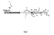
- each luminous body 3 travels inside the transparent resin without almost any loss and is introduced into inside of the transparent body 2 through the light introducing surface 2b and then diffuses in the direction of right, left, up or down. Then as shown by the light beam BM in Fig.
- the light emitted from the luminous bodies 3 is regular-reflected on the reflecting layer 41 arranged on the upper and lower surfaces of the light introducing section 21 and the outer surrounding surface 2e of the transparent body 2, travels inside the transparent body 2 until it reaches near the luminous surface 2c, and is further scatter-reflected on the reflecting layer 42 arranged to face the luminous surface 2c of the luminous section 22 of the transparent body 2, a part of the light is scattered also on the luminous surface 2c of the transparent body 2, and is finally emitted from the luminous surface 2c of the transparent body 2 uniformly.
- the light is emitted from the luminous surface 2c, since the luminous surface 2c is in a state of the frosted glass, the light is further scattered. As a result, whole of the luminous surface 2c surface-emits the light with a uniform luminous intensity.
- the lighting device 1 since the light emitted from the luminous bodies 3 is regular-reflected and stirred on the reflecting layer 41 arranged on the upper and lower surfaces of the light introducing section 21 and the outer surrounding surface 2e of the transparent body 2 and introduced inside the transparent body 2 without loss until it reaches the luminous surface 2c, it is possible to maintain the luminous intensity of the luminous surface 2c even though a total number of the luminous bodies is reduced.
- the light since the light travels while being regular-reflected on the reflecting layer 41 and scatter-reflected on the reflecting layer 42 even though a direction to which each luminous body 3 faces deviates to some extent, it is unlikely to generate unevenness in the luminous intensity.
- a thickness of the lighting device 1 can be set to be almost the same as an outer size of the luminous body 3, the lighting device 1 can be made low-bulky and eventually downsized.
- the transparent body 2 is assembled with the following procedures; first the luminous body mounting substrate 5 is arranged linearly as shown in Fig.
- each luminous body 3 is mounted on the luminous body mounting substrate 5 in line, next the luminous body mounting substrate 5 loaded with the luminous bodies 3 is placed on the flange 23 so that the luminous bodies 3 locate outside and face the light introducing surface 2b of the transparent body 2 by making use of a characteristic that the luminous body mounting substrate 5 is made of a flexible material such as a flexible substrate, and transparent silicon is filled into a space between the luminous bodies 3 and the transparent body 2, finally the cover section 7 is mounted.
- the reflecting layers 41, 42 may be previously arranged or may be arranged after the luminous bodies 3 are mounted.
- the electric power cable 8 is loaded on the luminous body mounting substrate 5 at the same time when the luminous bodies 3 are loaded at a time shown in Fig. 4 .
- the lighting device 1 in accordance with this invention is completed.
- a total number of the luminous bodies 3 is low as mentioned above and restrictions of assembling the lighting device 1 is reduced because the fluctuation affects the performance of the lighting device 1 is small even though each luminous body 3 is loaded in a direction with some fluctuation, time required for assembling becomes short and assembling procedure becomes simple as well.
- the present claimed invention is not limited to the above-mentioned embodiment.
- the luminous surface 2c may be in a shape of a concave of a circular cone with its head cut as shown in Fig. 6 .
- droplet that drops on a luminous surface 2c from the specimen slips off toward the center bore 11 and is discharged from the center bore 11 with ease.
- a side view style of a luminous body may be used as the luminous body 3 and the luminous body mounting substrate 5 may be disk-shaped.
- the luminous bodies 3 mount on the substrate 5 of a disk shape having a center bore in a standing posture along an outer circumference of the substrate 5 so that a luminous surface of the luminous body 3 faces a direction of the outer circumference by fittingly inserting a lead L of the luminous body 3 into a through hole (not shown in drawings) arranged on the substrate 5.
- the lighting device 1 is assembled by fittingly inserting the substrate 5 on which the luminous bodies 3 are mounted into the center bore 11 of the transparent body 2.
- the transparent body 2 may be colored in an arbitrary color.
- the luminous bodies 3 may be stroboscopically illuminated and may be set circumferentially in multiple lines if a bigger luminous intensity is required.
- the luminous body 3 is not limited to a monochromatic light, and red, blue and green may be used by mixture and the luminous surface 2c may emit the light in an arbitrary color by making use of its mixing ratio.
- the space between the transparent body 2 and the luminous body 3 may not be filled with the transparent resin. In this case, some uneven light emission might be generated near the light introducing surface 2b of the transparent body 2, however, enough lighting performance can be produced depending on an object to be inspected.
- Multiple concave sections may be arranged on the inner peripheral section of the transparent body 2 and the luminous body 3 may be accommodated in each of the concave sections.
- a ratio of the light introducing section 21 and the luminous section 22 of the transparent body 2 can be varied arbitrarily according to an object to be illuminated and the luminous section 22, namely the luminous surface 2c may be further narrowed.
- a shape of the transparent body used for the lighting device in accordance with this invention is not especially limited to a body of rotation having a center bore, and may be, for example, rectangle as shown in Fig. 8 .
- a shape of the center bore for monitoring or filming the specimen such as a product is circle in plane view, however, it is not limited to this and may be, for example, rectangle in plane view.
- the lighting device having the above arrangement in accordance with the present claimed invention can be used as a backlight lighting device and preferably used, for example, in case of inspecting a notch for positioning of a silicon wafer.
Applications Claiming Priority (2)
| Application Number | Priority Date | Filing Date | Title |
|---|---|---|---|
| JP2005245204 | 2005-08-26 | ||
| PCT/JP2006/316602 WO2007023891A1 (ja) | 2005-08-26 | 2006-08-24 | 照明装置 |
Publications (2)
| Publication Number | Publication Date |
|---|---|
| EP1925877A1 true EP1925877A1 (de) | 2008-05-28 |
| EP1925877A4 EP1925877A4 (de) | 2010-08-11 |
Family
ID=37771634
Family Applications (1)
| Application Number | Title | Priority Date | Filing Date |
|---|---|---|---|
| EP06796715A Withdrawn EP1925877A4 (de) | 2005-08-26 | 2006-08-24 | Beleuchtungsvorrichtung |
Country Status (4)
| Country | Link |
|---|---|
| US (1) | US7806540B2 (de) |
| EP (1) | EP1925877A4 (de) |
| JP (1) | JPWO2007023891A1 (de) |
| WO (1) | WO2007023891A1 (de) |
Cited By (4)
| Publication number | Priority date | Publication date | Assignee | Title |
|---|---|---|---|---|
| WO2013005151A1 (en) * | 2011-07-05 | 2013-01-10 | Koninklijke Philips Electronics N.V. | Lighting module |
| WO2013064948A1 (en) * | 2011-11-03 | 2013-05-10 | Koninklijke Philips Electronics N.V. | Led rear lamp, in particular for a bicycle |
| CN105074329A (zh) * | 2013-01-03 | 2015-11-18 | 标致·雪铁龙汽车公司 | 包括带有一个或多个发光边缘的屏幕的照明装置 |
| US9927446B2 (en) | 2006-05-30 | 2018-03-27 | Antibosyshop A/S | Methods and devices for rapid assessment of severity of injury |
Families Citing this family (24)
| Publication number | Priority date | Publication date | Assignee | Title |
|---|---|---|---|---|
| US7604361B2 (en) * | 2001-09-07 | 2009-10-20 | Litepanels Llc | Versatile lighting apparatus and associated kit |
| JP2009032430A (ja) * | 2007-07-25 | 2009-02-12 | Casio Comput Co Ltd | 照光装置 |
| TW201003006A (en) * | 2008-07-01 | 2010-01-16 | Pegatron Corp | Light guiding element, light emitting module and electronic apparatus |
| CN101738678A (zh) * | 2008-11-26 | 2010-06-16 | 鸿富锦精密工业(深圳)有限公司 | 导光板及显示装置 |
| US20100242337A1 (en) * | 2009-03-30 | 2010-09-30 | Steve Cummings | Ice fishing device |
| US8322884B2 (en) * | 2010-03-31 | 2012-12-04 | Abl Ip Holding Llc | Solid state lighting with selective matching of index of refraction |
| JP4975136B2 (ja) * | 2010-04-13 | 2012-07-11 | シャープ株式会社 | 照明装置 |
| CN102418888B (zh) * | 2010-08-23 | 2015-06-24 | 东芝照明技术株式会社 | 照明器具 |
| JP2012069511A (ja) * | 2010-08-23 | 2012-04-05 | Toshiba Lighting & Technology Corp | 照明器具 |
| JP5645684B2 (ja) * | 2011-01-27 | 2014-12-24 | 三菱電機株式会社 | 照明用光源及び照明装置 |
| CN102052622B (zh) * | 2011-01-30 | 2012-12-05 | 陈晓锋 | 新型多光效的灯具 |
| CN102052623A (zh) * | 2011-01-30 | 2011-05-11 | 陈晓锋 | 一种新型装饰照明灯 |
| JP5733509B2 (ja) | 2011-03-22 | 2015-06-10 | ミネベア株式会社 | 照明装置 |
| US9618678B1 (en) * | 2012-10-23 | 2017-04-11 | Cooper Technologies Company | Waveguide light fixtures |
| JP5496315B2 (ja) * | 2012-12-27 | 2014-05-21 | 三菱電機株式会社 | 導光体、照明ユニットおよび画像読取用照明装置 |
| JP6002071B2 (ja) * | 2013-03-26 | 2016-10-05 | 株式会社東芝 | 照明装置及び導光部材 |
| JP6136502B2 (ja) | 2013-04-15 | 2017-05-31 | ソニー株式会社 | 照明装置、照明システム |
| US9222627B2 (en) * | 2013-04-19 | 2015-12-29 | Abl Ip Holding Llc | Annulus shaped luminaire |
| USD725305S1 (en) | 2014-04-21 | 2015-03-24 | Abl Ip Holding Llc | Annulus shaped luminaire |
| USD725304S1 (en) | 2014-04-21 | 2015-03-24 | Abl Ip Holding Llc | Annulus shaped luminaire |
| US9765958B2 (en) * | 2015-05-21 | 2017-09-19 | Séura, Inc. | Illuminated mirror |
| US10073212B1 (en) * | 2017-06-09 | 2018-09-11 | Opto Tech Corporation | Lamp structure |
| CA3154642A1 (en) * | 2019-09-10 | 2021-03-18 | Hubbell Lighting, Inc. | Canopy luminaire |
| US11549680B2 (en) | 2020-07-08 | 2023-01-10 | Feit Electric Company, Inc. | Mirror with light emitting elements and stand |
Citations (4)
| Publication number | Priority date | Publication date | Assignee | Title |
|---|---|---|---|---|
| EP0732679A1 (de) * | 1995-03-16 | 1996-09-18 | Hayashi Telempu Co., Ltd. | Anzeigeeinrichtung für in Fahrzeuge eingebaute Instrumente |
| US5899557A (en) * | 1994-08-11 | 1999-05-04 | Mcdermott; Kevin | Multi-source lighting device |
| US6053621A (en) * | 1996-07-08 | 2000-04-25 | Ccs Co., Ltd. | Lighting unit for inspecting a surface |
| US6647199B1 (en) * | 1996-12-12 | 2003-11-11 | Teledyne Lighting And Display Products, Inc. | Lighting apparatus having low profile |
Family Cites Families (6)
| Publication number | Priority date | Publication date | Assignee | Title |
|---|---|---|---|---|
| JPH04138612A (ja) * | 1990-09-29 | 1992-05-13 | Mitsubishi Electric Corp | 照明装置 |
| JPH0563050A (ja) | 1991-08-29 | 1993-03-12 | Adotetsuku Eng:Kk | Icリードフレームの状態測定方法及び装置 |
| JPH0563050U (ja) * | 1992-01-31 | 1993-08-20 | エヌティエヌ株式会社 | バックライト付テーブル |
| AU695608B2 (en) * | 1995-06-07 | 1998-08-20 | Toyoda Gosei Co. Ltd. | Light-driven display device |
| US6900059B1 (en) * | 1999-11-26 | 2005-05-31 | Associates Of Cape Cod, Inc. | Reader for conducting assays |
| KR100634514B1 (ko) * | 2002-12-16 | 2006-10-16 | 가시오게산키 가부시키가이샤 | 조명장치 및 전자기기 |
-
2006
- 2006-08-24 WO PCT/JP2006/316602 patent/WO2007023891A1/ja active Application Filing
- 2006-08-24 JP JP2007532165A patent/JPWO2007023891A1/ja active Pending
- 2006-08-24 US US12/064,696 patent/US7806540B2/en not_active Expired - Fee Related
- 2006-08-24 EP EP06796715A patent/EP1925877A4/de not_active Withdrawn
Patent Citations (4)
| Publication number | Priority date | Publication date | Assignee | Title |
|---|---|---|---|---|
| US5899557A (en) * | 1994-08-11 | 1999-05-04 | Mcdermott; Kevin | Multi-source lighting device |
| EP0732679A1 (de) * | 1995-03-16 | 1996-09-18 | Hayashi Telempu Co., Ltd. | Anzeigeeinrichtung für in Fahrzeuge eingebaute Instrumente |
| US6053621A (en) * | 1996-07-08 | 2000-04-25 | Ccs Co., Ltd. | Lighting unit for inspecting a surface |
| US6647199B1 (en) * | 1996-12-12 | 2003-11-11 | Teledyne Lighting And Display Products, Inc. | Lighting apparatus having low profile |
Non-Patent Citations (1)
| Title |
|---|
| See also references of WO2007023891A1 * |
Cited By (8)
| Publication number | Priority date | Publication date | Assignee | Title |
|---|---|---|---|---|
| US9927446B2 (en) | 2006-05-30 | 2018-03-27 | Antibosyshop A/S | Methods and devices for rapid assessment of severity of injury |
| US11125761B2 (en) | 2006-05-30 | 2021-09-21 | Antibodyshop A/S | Methods and devices for rapid assessment of severity of injury |
| WO2013005151A1 (en) * | 2011-07-05 | 2013-01-10 | Koninklijke Philips Electronics N.V. | Lighting module |
| WO2013064948A1 (en) * | 2011-11-03 | 2013-05-10 | Koninklijke Philips Electronics N.V. | Led rear lamp, in particular for a bicycle |
| CN103890622A (zh) * | 2011-11-03 | 2014-06-25 | 皇家飞利浦有限公司 | 特别地用于自行车的led尾灯 |
| US9156511B2 (en) | 2011-11-03 | 2015-10-13 | Koninklijke Philips N.V. | LED rear lamp, in particular for a bicycle |
| CN105074329A (zh) * | 2013-01-03 | 2015-11-18 | 标致·雪铁龙汽车公司 | 包括带有一个或多个发光边缘的屏幕的照明装置 |
| CN105074329B (zh) * | 2013-01-03 | 2018-08-17 | 标致·雪铁龙汽车公司 | 包括带有一个或多个发光边缘的屏幕的照明装置 |
Also Published As
| Publication number | Publication date |
|---|---|
| JPWO2007023891A1 (ja) | 2009-02-26 |
| US20090129121A1 (en) | 2009-05-21 |
| US7806540B2 (en) | 2010-10-05 |
| EP1925877A4 (de) | 2010-08-11 |
| WO2007023891A1 (ja) | 2007-03-01 |
Similar Documents
| Publication | Publication Date | Title |
|---|---|---|
| EP1925877A1 (de) | Beleuchtungsvorrichtung | |
| US10288798B2 (en) | Illumination device in which source light injection is non-parallel to device's optical axis | |
| US6053621A (en) | Lighting unit for inspecting a surface | |
| JP5254744B2 (ja) | 照明用レンズおよびこれを備えた照明装置 | |
| KR100644935B1 (ko) | 평판형 발광 소자 | |
| JP4981064B2 (ja) | 放射状プリズム光偏向器を有するled発光体 | |
| EP3327339A1 (de) | Lichtleiterbeleuchtungsvorrichtung zur direkten-indirekten beleuchtung | |
| JP2008066032A (ja) | 照明装置 | |
| CN111025743B (zh) | 光源模块及显示装置 | |
| JP6481471B2 (ja) | 光学部材、発光装置及び照明装置 | |
| JP2010217109A (ja) | 発光素子測定装置 | |
| US11668647B2 (en) | Illumination unit with multiple light sources for generating a uniform illumination spot | |
| JP2012515897A (ja) | 楔状支持体を通した生体試料アレイの空間的に制御された照明 | |
| CN101341602A (zh) | Led光约束元件 | |
| TWI725321B (zh) | 照明裝置 | |
| JP6968330B2 (ja) | Led照明装置 | |
| US20080266877A1 (en) | Optical plate and backlight module using the same | |
| JP2010203922A (ja) | 検査用照明装置 | |
| WO2022202232A1 (ja) | 導光体、照明装置、イメージセンサおよび読取装置 | |
| JP2010204109A (ja) | 検査用照明装置 | |
| JP2022038514A (ja) | 照明器具 | |
| JP2009277614A (ja) | バックライト装置及び光測定装置 |
Legal Events
| Date | Code | Title | Description |
|---|---|---|---|
| PUAI | Public reference made under article 153(3) epc to a published international application that has entered the european phase |
Free format text: ORIGINAL CODE: 0009012 |
|
| 17P | Request for examination filed |
Effective date: 20080312 |
|
| AK | Designated contracting states |
Kind code of ref document: A1 Designated state(s): AT BE BG CH CY CZ DE DK EE ES FI FR GB GR HU IE IS IT LI LT LU LV MC NL PL PT RO SE SI SK TR |
|
| A4 | Supplementary search report drawn up and despatched |
Effective date: 20100714 |
|
| RIC1 | Information provided on ipc code assigned before grant |
Ipc: F21V 8/00 20060101AFI20070521BHEP Ipc: G02B 6/00 20060101ALI20100708BHEP Ipc: F21Y 101/02 20060101ALI20100708BHEP Ipc: G01N 21/84 20060101ALI20100708BHEP |
|
| 17Q | First examination report despatched |
Effective date: 20110308 |
|
| DAX | Request for extension of the european patent (deleted) | ||
| STAA | Information on the status of an ep patent application or granted ep patent |
Free format text: STATUS: THE APPLICATION IS DEEMED TO BE WITHDRAWN |
|
| 18D | Application deemed to be withdrawn |
Effective date: 20121016 |