EP1914847A2 - Connecteur de câble pour porte de véhicule - Google Patents
Connecteur de câble pour porte de véhicule Download PDFInfo
- Publication number
- EP1914847A2 EP1914847A2 EP07118229A EP07118229A EP1914847A2 EP 1914847 A2 EP1914847 A2 EP 1914847A2 EP 07118229 A EP07118229 A EP 07118229A EP 07118229 A EP07118229 A EP 07118229A EP 1914847 A2 EP1914847 A2 EP 1914847A2
- Authority
- EP
- European Patent Office
- Prior art keywords
- connector
- female connector
- male connector
- recesses
- vehicle body
- Prior art date
- Legal status (The legal status is an assumption and is not a legal conclusion. Google has not performed a legal analysis and makes no representation as to the accuracy of the status listed.)
- Granted
Links
Images


Classifications
-
- B—PERFORMING OPERATIONS; TRANSPORTING
- B60—VEHICLES IN GENERAL
- B60R—VEHICLES, VEHICLE FITTINGS, OR VEHICLE PARTS, NOT OTHERWISE PROVIDED FOR
- B60R16/00—Electric or fluid circuits specially adapted for vehicles and not otherwise provided for; Arrangement of elements of electric or fluid circuits specially adapted for vehicles and not otherwise provided for
- B60R16/02—Electric or fluid circuits specially adapted for vehicles and not otherwise provided for; Arrangement of elements of electric or fluid circuits specially adapted for vehicles and not otherwise provided for electric constitutive elements
- B60R16/0207—Wire harnesses
- B60R16/0215—Protecting, fastening and routing means therefor
-
- H—ELECTRICITY
- H01—ELECTRIC ELEMENTS
- H01R—ELECTRICALLY-CONDUCTIVE CONNECTIONS; STRUCTURAL ASSOCIATIONS OF A PLURALITY OF MUTUALLY-INSULATED ELECTRICAL CONNECTING ELEMENTS; COUPLING DEVICES; CURRENT COLLECTORS
- H01R13/00—Details of coupling devices of the kinds covered by groups H01R12/70 or H01R24/00 - H01R33/00
- H01R13/73—Means for mounting coupling parts to apparatus or structures, e.g. to a wall
- H01R13/74—Means for mounting coupling parts in openings of a panel
- H01R13/741—Means for mounting coupling parts in openings of a panel using snap fastening means
- H01R13/743—Means for mounting coupling parts in openings of a panel using snap fastening means integral with the housing
-
- B—PERFORMING OPERATIONS; TRANSPORTING
- B60—VEHICLES IN GENERAL
- B60J—WINDOWS, WINDSCREENS, NON-FIXED ROOFS, DOORS, OR SIMILAR DEVICES FOR VEHICLES; REMOVABLE EXTERNAL PROTECTIVE COVERINGS SPECIALLY ADAPTED FOR VEHICLES
- B60J5/00—Doors
- B60J5/04—Doors arranged at the vehicle sides
-
- H—ELECTRICITY
- H01—ELECTRIC ELEMENTS
- H01R—ELECTRICALLY-CONDUCTIVE CONNECTIONS; STRUCTURAL ASSOCIATIONS OF A PLURALITY OF MUTUALLY-INSULATED ELECTRICAL CONNECTING ELEMENTS; COUPLING DEVICES; CURRENT COLLECTORS
- H01R13/00—Details of coupling devices of the kinds covered by groups H01R12/70 or H01R24/00 - H01R33/00
- H01R13/62—Means for facilitating engagement or disengagement of coupling parts or for holding them in engagement
- H01R13/629—Additional means for facilitating engagement or disengagement of coupling parts, e.g. aligning or guiding means, levers, gas pressure electrical locking indicators, manufacturing tolerances
- H01R13/62905—Additional means for facilitating engagement or disengagement of coupling parts, e.g. aligning or guiding means, levers, gas pressure electrical locking indicators, manufacturing tolerances comprising a camming member
- H01R13/62911—U-shaped sliding element
-
- H—ELECTRICITY
- H02—GENERATION; CONVERSION OR DISTRIBUTION OF ELECTRIC POWER
- H02G—INSTALLATION OF ELECTRIC CABLES OR LINES, OR OF COMBINED OPTICAL AND ELECTRIC CABLES OR LINES
- H02G3/00—Installations of electric cables or lines or protective tubing therefor in or on buildings, equivalent structures or vehicles
- H02G3/02—Details
- H02G3/06—Joints for connecting lengths of protective tubing or channels, to each other or to casings, e.g. to distribution boxes; Ensuring electrical continuity in the joint
-
- H—ELECTRICITY
- H01—ELECTRIC ELEMENTS
- H01R—ELECTRICALLY-CONDUCTIVE CONNECTIONS; STRUCTURAL ASSOCIATIONS OF A PLURALITY OF MUTUALLY-INSULATED ELECTRICAL CONNECTING ELEMENTS; COUPLING DEVICES; CURRENT COLLECTORS
- H01R13/00—Details of coupling devices of the kinds covered by groups H01R12/70 or H01R24/00 - H01R33/00
- H01R13/46—Bases; Cases
- H01R13/52—Dustproof, splashproof, drip-proof, waterproof, or flameproof cases
- H01R13/5202—Sealing means between parts of housing or between housing part and a wall, e.g. sealing rings
-
- H—ELECTRICITY
- H01—ELECTRIC ELEMENTS
- H01R—ELECTRICALLY-CONDUCTIVE CONNECTIONS; STRUCTURAL ASSOCIATIONS OF A PLURALITY OF MUTUALLY-INSULATED ELECTRICAL CONNECTING ELEMENTS; COUPLING DEVICES; CURRENT COLLECTORS
- H01R2201/00—Connectors or connections adapted for particular applications
- H01R2201/26—Connectors or connections adapted for particular applications for vehicles
Definitions
- the present invention relates to a cable connector for a vehicle door, and more particularly, to a cable connector for a vehicle door which enables a worker to simply assemble a female connector and a male connector without using any coupling means such as a bolt, and to install a male connector to a panel of a vehicle body without any mistake.
- a door of a vehicle is provided with operating devices, such as a power window device, a door locking device, a side mirror adjusting device, etc., which are operated by a power source.
- the respective operating devices are connected to a main controller mounted in a vehicle body by cables so as to be controlled by a driver.
- the cables are drawn out from a side portion of the vehicle body, and are put into the door.
- a panel of the vehicle body is provided with cable connectors to connect the cables drawn out from the vehicle body and the cables extending from the respective operating devices mounted in the door.
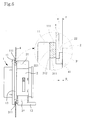
- FIG. 8 is a schematic view illustrating an installed state of a conventional cable connector of a vehicle
- FIG. 9 is an exploded perspective view illustrating an installed state of the conventional cable connector.
- the conventional cable connector includes a male connector 300 which is connected with a cable 10 drawn out from the interior of a vehicle body 100, and a female connector 400 which is connected with a cable 10 drawn out from the interior of a door 200 and is inserted into the male connector 300.
- the male connector 300 is provided with flanges 301 extending outwardly.
- the flanges 301 are formed with fixing holes 302 through which bolts 303 are tightened.
- the male connector 300 When mounting the conventional cable connector as structured above, the male connector 300, connected with the cable 10 drawn out from the vehicle body 100, is fitted through the connector mounting hole 102 formed at the panel 101 of the vehicle body, and then the flanges 301 of the male connector 300 are fixed to the panel 101 of the vehicle body by tightening the bolts 303 through the fixing holes 302 formed at the flanges 301.
- the female connector 400 connected with the cable 10 drawn out from the door 200 is engaged with the male connector 300, thereby completing the process of assembling the cable connector.
- the above conventional cable connector has the problem of taking much time to assemble, because the male connector is fixed to the panel of the vehicle body by tightening the bolts.
- the present invention has been made in view of the above problems, and it is an object of the present invention to provide a cable connector for a vehicle door that enables a worker to simply assemble a female connector and a male connector without using any coupling means such as a bolt.
- a cable connector for a vehicle door comprising: a male connector including a contact terminal, a fitting part, a flange provided between the contact terminal and the fitting part, and a waterproof seal; a female connector engageable with the fitting part of the male connector, the female connector including a contact terminal; a plurality of elastic members formed on an outer surface of the fitting part, the elastic members including latching recesses in which an edge or end of a connecter mounting hole of a panel of a vehicle body is fittable and a guide connecting device including cam recesses and locking recesses formed on the outer surface of the fitting part, and a slide lever slidably provided in the female connector, the slide lever having guide protrusions moveable along the cam recesses and locking protrusions lockable in the locking recesses.
- the female connector may be provided with at least one protruding portion at an end thereof to press the panel of the vehicle body so that the edge or end of the connector mounting hole can be fitted in the latching recesses of the elastic members.
- the protruding portion may have a protruding length which is equal to or longer than a distance between the end of the female connector and a latching end of each of the latching recesses when the female connector and the male connector are engaged.
- the protruding portion may include plural protruding portions which protrude from the end of the female connector.
- the protruding portion may be provided as a single body which protrudes from a whole circumference of the end of the female connector.
- a connector according to the first embodiment, shown in FIGS 1 to 3b includes a male connector 1 which is fitted through a connector mounting hole 41 formed in a panel 4 of a vehicle body and connected with a cable 10, a female connector 2 which fixes the male connector 1 to the connector mounting hole 41 and is connected with a cable 10, and a guide connecting device 3 which is provided at the female connector 2 and the male connector 1 to connect the female connector 2 and the male connector 1.
- the male connector 1 includes a contact terminal 12, a fitting part 13, a flange 11 provided between the contact terminal 12 and the fitting part 13, and a waterproof seal 111.
- the contact terminal 12 is connected with the cable 10 drawn out from the vehicle body, and the fitting part 13 is formed so as to be fitted through the connector mounting hole 41 formed in the panel 4 of the vehicle body.
- the waterproof seal 111 is provided on side portions of the flange 11 so that when the male connector 1 is fitted through the connector mounting hole 41 of the panel 4 of the vehicle body, the waterproof seal 111 closely contacts the panel 4 of the vehicle body around the connector mounting hole 41.
- the female connector 2 includes a contact terminal 23 which is inserted into the fitting part 13 of the male connector 1.
- the contact terminal 23 of the female connector 2 is connected with the cable 10 drawn out from the vehicle door.
- the cables 10 drawn out from the vehicle body and the door are connected to each other through the engagement of the female connector 2 and the male connector 1.
- the guide connecting device 3 includes cam recesses 32 and locking recesses 33 which are formed on the outer surface of the fitting part 13 of the male connector 1, and a slide lever 34 which is slidably provided in the female connector 2 and has guide protrusions 341 moveable along the cam recesses 32 and locking protrusions 342 lockable in the locking recesses 33.
- the cam recesses 32 and the locking recesses 33 are formed symmetrically on both the outer side surfaces of the fitting part 13 of the male connector 1.
- the guide protrusions 341 and the locking protrusions 342 are formed symmetrically on both the inner side surfaces of the slide lever 34, which is slidably provided in the female connector 2, so as to be moveable along the cam recesses 32 and to be lockable in the locking recesses 33 of the male connector 1.
- FIG. 3a and 3b illustrate a process of assembling the connector in accordance with the first embodiment of the present invention. More particularly, FIG. 3a illustrates a step of installing the male connector to the panel of the vehicle body and a step of temporarily engaging the female connector with the male connector, and FIG. 3b illustrates a step of assembling the connector.
- the male connector 1 is installed to the panel 4 of the vehicle body by inserting the fitting part 13 of the male connector 1 through the connector mounting hole 41 from the interior of the panel 4 of the vehicle body to the exterior.
- the female connector 2 is temporarily engaged with the fitting part 13 of the male connector 1.
- the female connector 2 and the male connector 1 are manufactured so that when the female connector 2 and the male connector 1 are engaged, a distance d between the end of the female connector 2 and a latching end 312 formed at the latching recess 311 of the male connector 1 is larger than zero, to generate a gap.
- the assembly defect of the female connector 2 and the male connector 1 can be prevented in advance by manufacturing the female and male connectors 2 and 1 so that the aforesaid distance d is set to be larger than zero.
- the connector according to the first embodiment of the present invention has an advantage of improving an assembly efficiency of the connector to the maximum, by enabling a worker to securely install the female and male connectors 2 and 1 to the panel 4 of the vehicle body by only the engaging process of the female and male connectors 2 and 1 without using any coupling means such as a bolt.
- FIGS 4 to 7c The connector according to the second embodiment is shown in FIGS 4 to 7c.
- the connector according to the second embodiment includes fundamentally all constituent components of the connector according to the first embodiment.
- the connector according to the second embodiment is constituted such that the distance d between the end of the female connector 2 and the latching end 312 formed at the latching recess 311 of the male connector 1 is larger than zero, to generate a gap, and a protruding portion 22 is provided at the end of the female connector 2 to press the panel 4 of the vehicle body so that the end of the connector mounting hole 41 can be perfectly fitted in the latching recesses 311 of the elastic members 31.
- the protruding portion 22 has a protruding length h which is equal to or longer than the distance d between the end of the female connector 2 and the latching end 312 of the latching recess 311 when the female connector 2 and the male connector 1 are engaged.
- the protruding length h is a length from the end of the female connector 2 to an end 221 of the protruding portion 22.
- the protruding portion 22 is provided in plural numbers on the end of the female connector 2. However, although it is not shown in the drawings, the protruding portion 22 may be provided in a single body which protrudes from the whole circumference of the end of the female connector 2.
- FIGS. 7a, 7b and 7c illustrate the process of assembling the connector in accordance with the second embodiment of the present invention. More particularly, FIG. 7a illustrates a step of installing the male connector to the panel of the vehicle body, FIG. 7b illustrates a step of engaging the female connector with the male connector, and FIG. 7c illustrates a step of assembling the connector.
- the female connector 2 and the male connector 1 can be assembled without a defect.
- the end of the connector mounting hole 41 can be fitted in the latching recesses 311 of the elastic members 31 through the operation of the slide lever 34.
- the protruding portion 22 of the female connector 2 pushes the panel 4 of the vehicle body. Through the process of pushing the panel 4 of the vehicle body by the protruding portion 22, the male connector 1 is pulled toward the female connector 2.
- the elastic members 31 provided at the male connector 1 are bent inwardly.
- the end of the connector mounting hole 41 of the panel 4 of the vehicle body is fitted in the latching recesses 311 of the elastic members 31.
- the protruding length h of the protruding portion 22 formed on the end of the female connector 2 is equal to or longer than the distance d between the end of the female connector 2 and the latching end 312 of the latching recess 311 when the female connector 2 and the male connector 1 are engaged, at the moment when the male connector 1 has been pulled completely to its fully seated position, the end of the connector mounting hole 41 of the panel 4 of the vehicle body is securely fitted in the latching recesses 311 of the elastic members 31.
- the male connector 1 can be securely fixed in the connector mounting hole 41 of the panel 4 of the vehicle body without a defect.
- the waterproof seal 111 provided on the flange 11 of the male connector 1 can closely contact the panel 4 of the vehicle body because the protruding length h of the protruding portion 22 is equal to or longer than the distance d between the end of the female connector 2 and the latching end 312 of the latching recess 311.
- the cable connector for a vehicle door can improve an assembly efficiency of the connector by enabling a worker to securely install the male connector to the panel of the vehicle body by only the engaging process of the female connector and the male connector without using a coupling means such as a bolt.
Landscapes
- Engineering & Computer Science (AREA)
- Mechanical Engineering (AREA)
- Architecture (AREA)
- Civil Engineering (AREA)
- Structural Engineering (AREA)
- Connector Housings Or Holding Contact Members (AREA)
- Details Of Connecting Devices For Male And Female Coupling (AREA)
Applications Claiming Priority (1)
| Application Number | Priority Date | Filing Date | Title |
|---|---|---|---|
| KR1020060101540A KR101552353B1 (ko) | 2006-10-18 | 2006-10-18 | 차량 도어용 케이블 연결 커넥터 |
Publications (3)
| Publication Number | Publication Date |
|---|---|
| EP1914847A2 true EP1914847A2 (fr) | 2008-04-23 |
| EP1914847A3 EP1914847A3 (fr) | 2008-10-15 |
| EP1914847B1 EP1914847B1 (fr) | 2013-01-23 |
Family
ID=38982638
Family Applications (1)
| Application Number | Title | Priority Date | Filing Date |
|---|---|---|---|
| EP07118229A Not-in-force EP1914847B1 (fr) | 2006-10-18 | 2007-10-10 | Connecteur de câble pour porte de véhicule |
Country Status (5)
| Country | Link |
|---|---|
| US (1) | US7520764B2 (fr) |
| EP (1) | EP1914847B1 (fr) |
| JP (1) | JP5211341B2 (fr) |
| KR (1) | KR101552353B1 (fr) |
| CN (1) | CN101286595B (fr) |
Cited By (5)
| Publication number | Priority date | Publication date | Assignee | Title |
|---|---|---|---|---|
| EP2456018A1 (fr) * | 2009-07-17 | 2012-05-23 | Yazaki Corporation | Structure imperméable |
| WO2013087472A1 (fr) * | 2011-12-13 | 2013-06-20 | Tyco Electronics Amp Gmbh | Adaptateur de fiche |
| EP2939883A1 (fr) * | 2014-04-29 | 2015-11-04 | Delphi Technologies, Inc. | Système d'étanchéité et de fixation de connecteur de porte |
| EP2998166A1 (fr) * | 2014-09-16 | 2016-03-23 | Delphi Technologies, Inc. | Système de fixation utilisable pour des connecteurs |
| CN110289524A (zh) * | 2018-03-19 | 2019-09-27 | 现代自动车株式会社 | 连接器的连接结构 |
Families Citing this family (23)
| Publication number | Priority date | Publication date | Assignee | Title |
|---|---|---|---|---|
| KR101455866B1 (ko) * | 2008-06-30 | 2014-11-03 | 타이코에이엠피(유) | 도어 커넥터 |
| JP5572372B2 (ja) * | 2009-12-07 | 2014-08-13 | 矢崎総業株式会社 | ワイヤハーネスの配索構造及びワイヤハーネス |
| KR200457449Y1 (ko) * | 2010-04-21 | 2012-01-06 | 히로세코리아 주식회사 | 단자 이중 지지 및 작업성 향상 구조를 갖는 커넥터 |
| JP5603152B2 (ja) * | 2010-06-25 | 2014-10-08 | 矢崎総業株式会社 | パッド部材の取り付け構造 |
| JP5654306B2 (ja) * | 2010-09-30 | 2015-01-14 | 矢崎総業株式会社 | 導電路接続構造 |
| JP5761035B2 (ja) * | 2012-01-10 | 2015-08-12 | 住友電装株式会社 | レバー式コネクタ |
| US9033729B2 (en) * | 2012-01-26 | 2015-05-19 | Tyco Electronics Corporation | Panel mounted connector assembly |
| CN103944005B (zh) * | 2013-01-23 | 2016-07-06 | 泰科电子(上海)有限公司 | 一种锁定机构 |
| KR102127388B1 (ko) * | 2013-11-04 | 2020-06-26 | 엘지전자 주식회사 | 커넥터 및 상기 커넥터가 구비된 의류처리장치 |
| KR102158689B1 (ko) * | 2013-11-04 | 2020-09-22 | 엘지전자 주식회사 | 커넥터 및 상기 커넥터가 구비된 의류처리장치 |
| CN103738272A (zh) * | 2013-12-25 | 2014-04-23 | 柳州正菱集团有限公司 | 一种汽车驾驶室出线结构 |
| KR101510044B1 (ko) * | 2014-02-21 | 2015-04-07 | 현대자동차주식회사 | 차량용 도어 커넥터 |
| KR102309292B1 (ko) * | 2015-01-05 | 2021-10-06 | 엘지전자 주식회사 | 의류처리장치 및 그 도어 |
| JP6607088B2 (ja) * | 2016-03-04 | 2019-11-20 | 住友電装株式会社 | コネクタ |
| WO2017173309A1 (fr) * | 2016-03-31 | 2017-10-05 | Molex, Llc | Connecteur à montage de panneau |
| CN107571813A (zh) | 2016-07-05 | 2018-01-12 | 福特环球技术公司 | 用于车辆的连接组件、线束夹组件及内饰组件 |
| CN106129734B (zh) * | 2016-08-31 | 2018-03-23 | 南京康尼科技实业有限公司 | 一种后安装式的矩形连接器 |
| JP6650115B2 (ja) * | 2016-11-02 | 2020-02-19 | 住友電装株式会社 | コネクタ |
| JP6592475B2 (ja) * | 2017-04-27 | 2019-10-16 | 矢崎総業株式会社 | レバー嵌合式コネクタ |
| CN108871261A (zh) * | 2018-07-23 | 2018-11-23 | 广州树熊文化传播有限公司 | 一种新型多面检测仪 |
| KR102238051B1 (ko) * | 2019-04-29 | 2021-04-08 | 현대자동차주식회사 | 차량용 고전압 정션박스 |
| JP7068243B2 (ja) * | 2019-08-09 | 2022-05-16 | ヒロセ電機株式会社 | 電気コネクタ組立体及びこれを有する電子機器 |
| JP7230753B2 (ja) * | 2019-09-26 | 2023-03-01 | 住友電装株式会社 | コネクタ |
Citations (2)
| Publication number | Priority date | Publication date | Assignee | Title |
|---|---|---|---|---|
| US5588858A (en) | 1995-03-15 | 1996-12-31 | Itt Corporation | Connector system with wedge and grommet retainer |
| US6183275B1 (en) | 1997-10-01 | 2001-02-06 | Sumitomo Wiring Systems, Ltd. | Panel mounted lever connector |
Family Cites Families (12)
| Publication number | Priority date | Publication date | Assignee | Title |
|---|---|---|---|---|
| US4586771A (en) * | 1985-03-04 | 1986-05-06 | Amp Incorporated | Connector assembly having camming system for mating and unmating |
| JPS6454275U (fr) * | 1987-09-25 | 1989-04-04 | ||
| US4973268A (en) * | 1989-10-10 | 1990-11-27 | Amp Incorporated | Multi-contact electrical connector with secondary lock |
| GB9219328D0 (en) * | 1992-09-11 | 1992-10-28 | Amp Gmbh | Automotive door-to-body electrical |
| JPH06215827A (ja) * | 1993-01-18 | 1994-08-05 | Amp Japan Ltd | カム部材付きコネクタ |
| FR2730588B1 (fr) * | 1995-02-13 | 1997-03-28 | Cinch Connecteurs Sa | Perfectionnements aux connecteurs electriques |
| JP3399305B2 (ja) * | 1997-08-11 | 2003-04-21 | 住友電装株式会社 | コネクタ |
| JP3865278B2 (ja) | 1998-03-11 | 2007-01-10 | 矢崎総業株式会社 | 自動車ドア用コネクタの接続構造 |
| JP3541695B2 (ja) * | 1998-11-11 | 2004-07-14 | 住友電装株式会社 | パネル取付型コネクタ |
| DE29823075U1 (de) | 1998-12-24 | 2000-05-04 | Grote & Hartmann Gmbh & Co Kg, 42369 Wuppertal | Steckverbindergehäusekupplung |
| US6860759B2 (en) * | 2001-12-17 | 2005-03-01 | Sumitomo Wiring Systems, Ltd. | Connector and method of mounting a connector housing on a panel |
| JP4285376B2 (ja) * | 2004-09-06 | 2009-06-24 | 住友電装株式会社 | レバー式コネクタ |
-
2006
- 2006-10-18 KR KR1020060101540A patent/KR101552353B1/ko active IP Right Grant
-
2007
- 2007-10-04 JP JP2007260568A patent/JP5211341B2/ja not_active Expired - Fee Related
- 2007-10-10 US US11/869,953 patent/US7520764B2/en active Active
- 2007-10-10 EP EP07118229A patent/EP1914847B1/fr not_active Not-in-force
- 2007-10-18 CN CN2007101800663A patent/CN101286595B/zh active Active
Patent Citations (2)
| Publication number | Priority date | Publication date | Assignee | Title |
|---|---|---|---|---|
| US5588858A (en) | 1995-03-15 | 1996-12-31 | Itt Corporation | Connector system with wedge and grommet retainer |
| US6183275B1 (en) | 1997-10-01 | 2001-02-06 | Sumitomo Wiring Systems, Ltd. | Panel mounted lever connector |
Cited By (10)
| Publication number | Priority date | Publication date | Assignee | Title |
|---|---|---|---|---|
| EP2456018A1 (fr) * | 2009-07-17 | 2012-05-23 | Yazaki Corporation | Structure imperméable |
| EP2456018A4 (fr) * | 2009-07-17 | 2012-11-28 | Yazaki Corp | Structure imperméable |
| US8808026B2 (en) | 2009-07-17 | 2014-08-19 | Yazaki Corporation | Waterproof structure |
| WO2013087472A1 (fr) * | 2011-12-13 | 2013-06-20 | Tyco Electronics Amp Gmbh | Adaptateur de fiche |
| EP2939883A1 (fr) * | 2014-04-29 | 2015-11-04 | Delphi Technologies, Inc. | Système d'étanchéité et de fixation de connecteur de porte |
| WO2015165917A1 (fr) * | 2014-04-29 | 2015-11-05 | Delphi Technologies, Inc. | Système de fixation et d'étanchéité pour raccord de porte |
| EP2998166A1 (fr) * | 2014-09-16 | 2016-03-23 | Delphi Technologies, Inc. | Système de fixation utilisable pour des connecteurs |
| US9590348B2 (en) | 2014-09-16 | 2017-03-07 | Delphi Technologies, Inc. | Serviceable fixing system for connectors |
| CN110289524A (zh) * | 2018-03-19 | 2019-09-27 | 现代自动车株式会社 | 连接器的连接结构 |
| CN110289524B (zh) * | 2018-03-19 | 2022-04-01 | 现代自动车株式会社 | 连接器的连接结构 |
Also Published As
| Publication number | Publication date |
|---|---|
| EP1914847A3 (fr) | 2008-10-15 |
| CN101286595A (zh) | 2008-10-15 |
| KR20080035199A (ko) | 2008-04-23 |
| US7520764B2 (en) | 2009-04-21 |
| KR101552353B1 (ko) | 2015-09-10 |
| CN101286595B (zh) | 2013-08-28 |
| JP2008103325A (ja) | 2008-05-01 |
| US20080096407A1 (en) | 2008-04-24 |
| EP1914847B1 (fr) | 2013-01-23 |
| JP5211341B2 (ja) | 2013-06-12 |
Similar Documents
| Publication | Publication Date | Title |
|---|---|---|
| EP1914847A2 (fr) | Connecteur de câble pour porte de véhicule | |
| EP0572012B1 (fr) | Connecteur monté sur un bâti | |
| US6183275B1 (en) | Panel mounted lever connector | |
| US6203364B1 (en) | Electrical connector having slide clip attachment | |
| US6217358B1 (en) | Connector coupling structure | |
| JP2008533684A (ja) | コネクタ位置保証装置を有するレバー嵌合型コネクタ組立体 | |
| KR20170120115A (ko) | 체결 장치를 구비하는 플러그 커넥터 | |
| US20170155210A1 (en) | Cable strain relief | |
| JP4343197B2 (ja) | ロック機構を備えた接続装置 | |
| US9048577B2 (en) | Lever connector with waterproofing | |
| JPH09245869A (ja) | 端子係止具付きコネクタ | |
| KR20090112479A (ko) | 자동차용 도어 커넥터 | |
| EP1006380B1 (fr) | Connecteur électrique et/ou optique | |
| JPH10261464A (ja) | コネクタ装置 | |
| US20010021607A1 (en) | Electrical plug-in connector for providing an electrical connection between two regions separated by a partition wall | |
| CA2637423A1 (fr) | Dispositif de commutation de distribution electrique avec boitier isolant | |
| JPH10321281A (ja) | コネクタ | |
| KR101373424B1 (ko) | 차량 도어용 케이블 연결 커넥터 | |
| EP1955417B1 (fr) | Connecteur électrique pour montage dans une découpe de panneau | |
| JP3901956B2 (ja) | 補器のブラケット結合構造 | |
| JP7477611B2 (ja) | 送電線のシールド導体のための接続デバイス | |
| JP4177059B2 (ja) | コネクタ及びコネクタを備えたモジュール | |
| JP5180553B2 (ja) | コネクタ | |
| JP2024153314A (ja) | コネクタ | |
| JP2857732B2 (ja) | 電気コネクタ |
Legal Events
| Date | Code | Title | Description |
|---|---|---|---|
| PUAI | Public reference made under article 153(3) epc to a published international application that has entered the european phase |
Free format text: ORIGINAL CODE: 0009012 |
|
| AK | Designated contracting states |
Kind code of ref document: A2 Designated state(s): AT BE BG CH CY CZ DE DK EE ES FI FR GB GR HU IE IS IT LI LT LU LV MC MT NL PL PT RO SE SI SK TR |
|
| AX | Request for extension of the european patent |
Extension state: AL BA HR MK RS |
|
| PUAL | Search report despatched |
Free format text: ORIGINAL CODE: 0009013 |
|
| AK | Designated contracting states |
Kind code of ref document: A3 Designated state(s): AT BE BG CH CY CZ DE DK EE ES FI FR GB GR HU IE IS IT LI LT LU LV MC MT NL PL PT RO SE SI SK TR |
|
| AX | Request for extension of the european patent |
Extension state: AL BA HR MK RS |
|
| 17P | Request for examination filed |
Effective date: 20090313 |
|
| 17Q | First examination report despatched |
Effective date: 20090417 |
|
| AKX | Designation fees paid |
Designated state(s): CZ DE SK |
|
| GRAJ | Information related to disapproval of communication of intention to grant by the applicant or resumption of examination proceedings by the epo deleted |
Free format text: ORIGINAL CODE: EPIDOSDIGR1 |
|
| GRAP | Despatch of communication of intention to grant a patent |
Free format text: ORIGINAL CODE: EPIDOSNIGR1 |
|
| GRAP | Despatch of communication of intention to grant a patent |
Free format text: ORIGINAL CODE: EPIDOSNIGR1 |
|
| RAP1 | Party data changed (applicant data changed or rights of an application transferred) |
Owner name: TYCO ELECTRONICS AMP KOREA LIMITED |
|
| GRAS | Grant fee paid |
Free format text: ORIGINAL CODE: EPIDOSNIGR3 |
|
| GRAA | (expected) grant |
Free format text: ORIGINAL CODE: 0009210 |
|
| AK | Designated contracting states |
Kind code of ref document: B1 Designated state(s): CZ DE SK |
|
| REG | Reference to a national code |
Ref country code: DE Ref legal event code: R096 Ref document number: 602007028188 Country of ref document: DE Effective date: 20130321 |
|
| REG | Reference to a national code |
Ref country code: SK Ref legal event code: T3 Ref document number: E 13907 Country of ref document: SK |
|
| PLBE | No opposition filed within time limit |
Free format text: ORIGINAL CODE: 0009261 |
|
| STAA | Information on the status of an ep patent application or granted ep patent |
Free format text: STATUS: NO OPPOSITION FILED WITHIN TIME LIMIT |
|
| 26N | No opposition filed |
Effective date: 20131024 |
|
| REG | Reference to a national code |
Ref country code: DE Ref legal event code: R097 Ref document number: 602007028188 Country of ref document: DE Effective date: 20131024 |
|
| PGFP | Annual fee paid to national office [announced via postgrant information from national office to epo] |
Ref country code: CZ Payment date: 20180918 Year of fee payment: 12 Ref country code: SK Payment date: 20180917 Year of fee payment: 12 |
|
| PGFP | Annual fee paid to national office [announced via postgrant information from national office to epo] |
Ref country code: DE Payment date: 20180925 Year of fee payment: 12 |
|
| REG | Reference to a national code |
Ref country code: DE Ref legal event code: R119 Ref document number: 602007028188 Country of ref document: DE |
|
| REG | Reference to a national code |
Ref country code: SK Ref legal event code: MM4A Ref document number: E 13907 Country of ref document: SK Effective date: 20191010 |
|
| PG25 | Lapsed in a contracting state [announced via postgrant information from national office to epo] |
Ref country code: CZ Free format text: LAPSE BECAUSE OF NON-PAYMENT OF DUE FEES Effective date: 20191010 Ref country code: DE Free format text: LAPSE BECAUSE OF NON-PAYMENT OF DUE FEES Effective date: 20200501 |
|
| PG25 | Lapsed in a contracting state [announced via postgrant information from national office to epo] |
Ref country code: SK Free format text: LAPSE BECAUSE OF NON-PAYMENT OF DUE FEES Effective date: 20191010 |