EP1908862B1 - Système d'entraînement de lames pour métier à tisser - Google Patents
Système d'entraînement de lames pour métier à tisser Download PDFInfo
- Publication number
- EP1908862B1 EP1908862B1 EP06021001A EP06021001A EP1908862B1 EP 1908862 B1 EP1908862 B1 EP 1908862B1 EP 06021001 A EP06021001 A EP 06021001A EP 06021001 A EP06021001 A EP 06021001A EP 1908862 B1 EP1908862 B1 EP 1908862B1
- Authority
- EP
- European Patent Office
- Prior art keywords
- cam
- section
- shaft
- drive
- gear
- Prior art date
- Legal status (The legal status is an assumption and is not a legal conclusion. Google has not performed a legal analysis and makes no representation as to the accuracy of the status listed.)
- Not-in-force
Links
- 230000008878 coupling Effects 0.000 claims description 26
- 238000010168 coupling process Methods 0.000 claims description 26
- 238000005859 coupling reaction Methods 0.000 claims description 26
- 238000000926 separation method Methods 0.000 claims description 10
- 238000009941 weaving Methods 0.000 claims description 6
- 230000033001 locomotion Effects 0.000 description 10
- 230000005540 biological transmission Effects 0.000 description 9
- 238000005452 bending Methods 0.000 description 3
- 230000002093 peripheral effect Effects 0.000 description 3
- 238000005096 rolling process Methods 0.000 description 2
- 230000000712 assembly Effects 0.000 description 1
- 238000000429 assembly Methods 0.000 description 1
- 230000000295 complement effect Effects 0.000 description 1
- 230000001419 dependent effect Effects 0.000 description 1
- 238000009434 installation Methods 0.000 description 1
- 230000003534 oscillatory effect Effects 0.000 description 1
Images


Classifications
-
- D—TEXTILES; PAPER
- D03—WEAVING
- D03C—SHEDDING MECHANISMS; PATTERN CARDS OR CHAINS; PUNCHING OF CARDS; DESIGNING PATTERNS
- D03C5/00—Cam or other direct-acting shedding mechanisms, i.e. operating heald frames without intervening power-supplying devices
- D03C5/02—Cam or other direct-acting shedding mechanisms, i.e. operating heald frames without intervening power-supplying devices operated by rotating cams
Definitions
- the invention relates to a transmission for a loom.
- the DE 1 535 221 A1 describes a dobby of a loom.
- the Schaftmaschiene far more connected via gearbox with a common driven shaft Wellenanodnungen on.
- the shaft assemblies each consist of a permanently coupled to the driven shaft Drive section, which can be coupled via a coupling with a Kurvenlyanisme.
- On the cam carrier section sits a cam, which serves to move an associated weaving shank.
- Each weave of the loom is associated with a shaft assembly with a cam.
- a shaft gear which comprises a gear rack with a rotatably mounted shaft carrying a plurality of cams.
- the cams are associated with cam follower means which operate rockers.
- On the wings of a linkage for transmitting the drive movement is connected to the respective weaving shank.
- the shaft is driven via a bevel gear, which is formed by a ring gear and a bevel gear, by a drive shaft which is connected to a prime mover.
- each cam determines the shape of the vibration of the associated heald. Occasionally the task is to change the form of the movement. For this purpose, the cams must be replaced.
- the above-mentioned document proposes to provide the shaft at its end remote from the angular gear with a removable end piece which is mounted in a bearing device, which in turn is releasably held on the gear frame. If the cams are to be replaced, the bearing device is released from the gear frame. Furthermore, the tail is released from the shaft. Thereafter, the existing end piece and bearing unit can be removed, leaving a narrow gap between the free end of the shaft and the gear rack. Through this single, axially withdrawn from the shaft cams from the Gearbox removed and reversed new cams are applied to the shaft.
- the shaft gear according to the invention uses as a shaft for a plurality of cams a shaft arrangement, which can also be regarded as a split shaft.
- the shaft is thus subdivided into a cam carrier section and a drive section which, in use, are non-rotatably connected to one another at a separation point, for example by means of a suitable coupling device, and are preferably connected to one another in a bending-resistant manner. If one or more cams are to be exchanged, the cam carrier section and the drive section of the shaft arrangement are separated from one another. While the cam carrier portion and the cams may be removed from the gear rack, the drive portion may remain in the stem gear. Therefore, the gears of the gear train remain engaged with each other. After reassembly, the existing backlash of the gears, which has been kept very accurately, must not be readjusted.
- a plurality of cams are provided which form a package which is releasably connected to the cam carrier portion.
- the cams can sit on a bush, which is axially slidably connected to the cam carrier portion but rotatably connected.
- the cam carrier section can then be pulled axially during disassembly out of the package of cams, after which the cams or the package formed from the cams can be taken laterally out of the installation space.
- the drive section of the shaft assembly is preferably associated with at least one bearing device which is arranged between the separation point and the gear. It holds the drive section in the gear rack while the cam carrier section and cams may be taken out of the gear rack.
- the drive portion forms only a short, little or not beyond the bearing means out standing stub shaft.
- the separation point or coupling device is thus preferably arranged directly next to the bearing device, which is arranged between the cam plate and the gear. This can be done by removing the Cam carrier section of the free space between the two storage facilities along the entire length of the cam disc set are made free.
- the cam carrier section is preferably held axially displaceably in a bearing device.
- the axial position of the shaft assembly is preferably determined by the bearing means between the cam and gear. After releasing the separation point between the cam carrier section and the drive section, the cam carrier section can be pulled axially out of its bearing device.
- the disassembly and assembly of the shaft assembly is particularly simple.
- a coupling device is preferably provided which may be designed as a friction-locked and / or as a positive-locking coupling.
- the coupling device may include a backlash-free frictional coupling, e.g. be in the form of a cone clutch.
- a tightening screw or other suitable tensioning means can secure the cam carrier section and the drive section to one another and thus hold the coupling device in the engaged state.
- a suitable Abdschreibstoffstoff allows, if necessary, the separation of the cone connection.
- the coupling device can be designed as a positive toothed coupling.
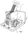
- FIG. 1 is a belonging to a loom arrangement consisting of a weaving shank 1, a drive serving him linkage 2 and a shaft gear 3 illustrated.
- the shaft gear 3 has, for each heald shaft to be driven, a rocker 4 which, as indicated by an arrow 5, performs a swinging reciprocating movement which is transmitted to the heald 1 via the linkage 2.
- the shaft gear 3 derives this oscillating movement from the uniformly rotating movement of a drive shaft 6, which is connected to an electric motor, not further illustrated.
- the electric motor may be a separate, only the shaft gear 3 driving motor or the main drive of the loom.
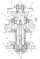
- FIG. 2 shows, via a gear transmission 7, a shaft assembly 8, for example according to FIG. 3 , at.
- the drive shaft 6 and the shaft assembly 8 are rotatably mounted in a gear frame 9, the in FIG. 2 illustrated with removed hood.
- the gear transmission 7 is formed as an angle gear. It has a ring gear 10 which is rotatably connected to the shaft assembly 8. It meshes with a pinion 11 which is rotatably connected to the drive shaft 6.
- the bearing device 12 is preferably designed as a ball bearing, while the bearing device 13 may be, for example, a needle or roller bearings. While the storage device 13 in the substantially flat wall 15 arranged flush on both sides may be, the wall 14 preferably has a in the direction of the ring gear 10 projecting pipe flange 16 which carries at its end facing the ring gear 10, the ball bearing of the bearing device 12.
- the bearing device 12 secures the axial position of the shaft assembly 8 and thus of the ring gear 10 and thus defines the backlash of the gear transmission 7.
- the shaft assembly 8 is how FIG. 3 illustrated by an example, shared. It has a drive section 17 and a cam carrier section 18 which are non-rotatably connected by a coupling device 19 in use, bending resistant and axially fixed together and both are arranged coaxially to a rotation axis 20, which is determined by the storage facilities 12, 13.
- the drive section 17 is screwed to the ring gear 10.
- washers 21, a receiving cone 22, a plurality of screws 23 and a clamping piece 24 serve.
- a pressure sleeve 25 carries on its outer peripheral surface, the ball bearing of the bearing device 12, whose inner ring is between a radial flange of the pressure sleeve 25 and a threaded ring 26 taken outside of the pressure sleeve 25 sits.
- the pressure sleeve finds its axial abutment on a corresponding shoulder 27 of the drive portion 17th
- the cam carrier portion 18 of the shaft assembly 8 carries on its outer peripheral surface a package 28 of at least one, preferably a plurality of cams 29 to 29i, which can sit on a common carrier sleeve 30 to form a package. These serve to drive the rocker. 4 and the other wings 4a to 4i. Except for the optionally individual shape of the cam plates 29 or 29a to 29i, the gear arrangements formed from the respective cam plate 29 to 29i and the rocker 4 to 4i coincide with one another.
- FIG. 5 illustrates such a gear assembly 31 using the example of the rocker 4 and the cam 29.
- the cam plate 29, which is formed of two complementary disks 29 ', 29 ", two cam followers 32, 33 are associated in the form of rollers, with parallel axes of rotation at a Rocker 34 are mounted and roll on the non-circular outer peripheral surface of the cam 29. This rotates about the rotation axis 20, which is oriented parallel to the axes of rotation of the cam followers 32, 33.
- the rocker 4 On the rocker 34, the rocker 4 is fixed, corresponding to the radial evasive movement of Cam follower 32, 33 performs a swinging motion when the cam 29 rotates.
- the package 28 is seated between two discs 35, 36 fixed to the carrier sleeve 30.
- the cams 29 to 29i may also be connected to the carrier sleeve in fixed rotational positions.
- the cam disks 29 to 29i can be relatively positioned relative to each other by index bolts or other alignment means.
- they can be secured by a profile toothing, index pin or other means in a fixed rotational position with respect to the carrier sleeve 30.
- the carrier sleeve 30 can turn be secured by suitable means, such as tongue and groove connection, spline, clamping screw, pin connections or the like rotatably on the cam carrier portion 18.
- the cam carrier portion 18 of the shaft assembly 8 is a preferably centrally hollow drilled shaft which extends through the bearing means 13. He can wear an inner ring 37, on the outer periphery of the rolling elements of the bearing device 13 roll. However, the inner ring 37 can be seated on the cam carrier section 18 in a play-like or clearance-free manner and can be placed on a radial collar 38 of the cam carrier section 18.
- the other end of the cam carrier section 18 is connected to the drive section 17.
- it is preferably cone-shaped, so that a cone 39 is formed.
- the cone 39 and the recess 40 are arranged coaxially to the rotation axis 20 and form the coupling device 19 in Shape of a cone clutch or a tapered joint connection. It causes in the coupled state a rotationally fixed and bending-resistant connection of the drive portion 17 and the cam carrier portion 18 with each other.
- the cone clutch has the merit of being connected to the cam support portion 18 in each relative rotational position of the drive portion 17, i. can be engaged. If a specific rotational position is to be specified, a positive-locking means can also be provided, which allows the engagement only in a certain rotational position.
- a suitable securing means 41 is provided, for example in the form of a securing bolt 42 extending through the central bore of the cam carrier section 18 into a threaded blind bore 43 extends into it.
- the bolt 42 is tightened in the threaded blind bore 43, so that its head 44 exerts axial pressure on the cam carrier portion 18 and clamps the cone 39 in the recess 40.
- the execution according to FIG. 3 requires that the distance between the inner shoulder of the radial collar 38 and the end 45 of the drive portion 17 with the width of the package 28 and the width of the discs 35 and 36 and the width of the inner ring 37 matches, so that the bolt 42 clamps these parts together. This is necessary if there is only a frictional connection between the cams 29 and the carrier sleeve 30, ie the cams 29 are slid onto the carrier sleeve 30 without play.
- the bolt 42 simultaneously braces the cam carrier section 18 with the drive section 17 and the cam track 28.
- the cam carrier portion 18 end with its end 46 within the inner ring 37. He thus has no radial collar 38.
- the curve package 28 is clamped between the discs 35 and 36 and the inner ring 37 by means of a clamping plate 47. This is fastened with fastening means 48 in threaded bores 49 of the cam carrier section 18. Otherwise, the previous description applies on the basis of the same reference numerals accordingly.
- the shaft gear 3 described so far operates as follows:
- the drive shaft 6 rotates via the gear transmission 7, the shaft assembly 8 and with this the cam 29 to 29i. Accordingly, perform the swing 4 to 4i oscillatory movements, which are transmitted to the corresponding heald frames.
- the package 28 is replaced.
- the machine is stopped and the hood of the shaft gear 3 removed. Thereafter, the bolt 44 is released. If the cone 39 is stuck in the recess 40, it is released.
- the through bore of the cam carrier section 18 may be provided with an internal thread into which a bolt is screwed, which is supported with a tapered smooth end at the bottom of the threaded blind bore 43.
- one or more tapped holes may pass through the cam carrier section 18 parallel to the central bore, into which jacking screws are inserted. Further possibilities for releasing a cone connection are familiar to the person skilled in the art.
- the cam carrier section 18 can be pulled out of the bearing device 13 axially.
- the package 28 is free and can be out as a whole from the space between the walls 14, 15 laterally out.
- the coupling means 19 is disposed in the space enclosed by the pipe flange 16 between the package 28 and the ring gear 10 outside of the space enclosed by the package 29.
- the coupling device 19 is preferably located between the bearing device 12 and the package 28, as shown.
- a shaft gear 3 for a loom has a shaft assembly 8 which carries at one end a ring gear 10 for driving the shaft assembly 8.
- the shaft assembly 8 is supported by means of two bearing devices 12, 13, between which on the shaft assembly 8, a package 28 is held rotatably with cams 29 to 29i.
- the package 28 carrying part 18 of the shaft assembly 8 is connected to the remaining part 17 of the shaft assembly 8 via a coupling device 19 which forms a separation point.
- the coupling device 19 is formed, for example, as a frictional coupling with cone 39 and corresponding recess 40 and secured with a one of an end of the shaft assembly 8 to be actuated securing means 41 in the connected state.
- connection can be released and the cam carrier portion 18 are removed from the shaft gear 3, wherein the drive portion 17 remains in the shaft gear 3.
- the package 18 can thus be changed as a whole, without having to disassemble the gear drive, which drives the shaft assembly 8.
Landscapes
- Engineering & Computer Science (AREA)
- Textile Engineering (AREA)
- Looms (AREA)
Claims (9)
- Mécanisme (3) d'entraînement de lames destiné à un métier à tisser automatique, comportant un châssis de mécanisme (9),
ledit mécanisme étant doté d'un dispositif (8) d'arbres qui est monté à rotation dans le châssis de mécanisme (9) et qui présente au moins une section (18) de support de cames et une section d'entraînement (17), qui peuvent être séparées l'une de l'autre,
comportant plusieurs disques de came (29 ... 29i) qui sont maintenus sur la première section (18) de support de cames, les disques de came (29 ... 29i) formant un paquet (28) qui est relié de façon démontable à la section (18) de support de cames,
comportant un engrenage à roues dentées (7) qui comprend au moins deux roues dentées (10, 11) qui sont en prise glissante et dont une est reliée de façon fixe en rotation avec la section d'entraînement (17) du dispositif d'arbres (8) et dont l'autre est reliée de façon fixe en rotation à un arbre d'entraînement (6). - Mécanisme d'entraînement de lames selon la revendication 1, caractérisé en ce qu'un point de séparation est déterminé entre la première section (18) de support de cames et la section d'entraînement (17), lequel point de séparation est disposé entre le disque de came (29) et la roue dentée (10) reliée à la section d'entraînement (17).
- Mécanisme d'entraînement de lames selon la revendication 1, caractérisé en ce qu'au moins un dispositif de palier (12) est affecté à la section d'entraînement (17), en ce qu'un point de séparation est prévu entre la section (18) de support de cames et la section d'entraînement (17) et en ce que le point de séparation est agencé entre le dispositif de palier (12) et le disque de came (29).
- Mécanisme d'entraînement de lames selon la revendication 1, caractérisé en ce qu'un dispositif de palier (13) est affecté à la section (18) de support de cames et en ce que la section (18) de support de cames est maintenue dans le dispositif de palier (13) de manière à pouvoir coulisser axialement.
- Mécanisme d'entraînement de lames selon la revendication 1, caractérisé en ce qu'un dispositif d'accouplement (19) est réalisé entre la section (18) de support de cames et la section d'entraînement (17), lequel dispositif d'accouplement (19), à l'état accouplé, relie entre elles de façon rigide la section (18) de support de cames et la section d'entraînement (17).
- Mécanisme d'entraînement de lames selon la revendication 5, caractérisé en ce que le dispositif d'accouplement (19) est un embrayage à friction sans jeu.
- Mécanisme d'entraînement de lames selon la revendication 5, caractérisé en ce que le dispositif d'accouplement (19) est un embrayage conique.
- Mécanisme d'entraînement de lames selon la revendication 5, caractérisé en ce que le dispositif d'accouplement (19) présente un moyen de serrage (41) destiné à assurer l'état serré du dispositif d'accouplement (19).
- Mécanisme d'entraînement de lames selon la revendication 1, caractérisé en ce que l'engrenage (7) à roues dentées est un engrenage d'angle.
Priority Applications (5)
| Application Number | Priority Date | Filing Date | Title |
|---|---|---|---|
| EP06021001A EP1908862B1 (fr) | 2006-10-06 | 2006-10-06 | Système d'entraînement de lames pour métier à tisser |
| DE502006006342T DE502006006342D1 (de) | 2006-10-06 | 2006-10-06 | Schaftgetriebe für eine Webmaschine |
| CN200710163079XA CN101161888B (zh) | 2006-10-06 | 2007-09-30 | 用于织机的轴传动装置 |
| JP2007261914A JP4617340B2 (ja) | 2006-10-06 | 2007-10-05 | 織機用シャフト伝動装置 |
| US11/907,035 US7594522B2 (en) | 2006-10-06 | 2007-10-09 | Shaft transmission for a weaving machine |
Applications Claiming Priority (1)
| Application Number | Priority Date | Filing Date | Title |
|---|---|---|---|
| EP06021001A EP1908862B1 (fr) | 2006-10-06 | 2006-10-06 | Système d'entraînement de lames pour métier à tisser |
Publications (2)
| Publication Number | Publication Date |
|---|---|
| EP1908862A1 EP1908862A1 (fr) | 2008-04-09 |
| EP1908862B1 true EP1908862B1 (fr) | 2010-03-03 |
Family
ID=37813515
Family Applications (1)
| Application Number | Title | Priority Date | Filing Date |
|---|---|---|---|
| EP06021001A Not-in-force EP1908862B1 (fr) | 2006-10-06 | 2006-10-06 | Système d'entraînement de lames pour métier à tisser |
Country Status (5)
| Country | Link |
|---|---|
| US (1) | US7594522B2 (fr) |
| EP (1) | EP1908862B1 (fr) |
| JP (1) | JP4617340B2 (fr) |
| CN (1) | CN101161888B (fr) |
| DE (1) | DE502006006342D1 (fr) |
Families Citing this family (6)
| Publication number | Priority date | Publication date | Assignee | Title |
|---|---|---|---|---|
| EP2180092B1 (fr) * | 2008-10-24 | 2012-11-21 | Groz-Beckert KG | Tendeur de largeur doté d'un dispositif de serrage et d'ouvrir |
| EP2322702B1 (fr) * | 2009-11-13 | 2013-04-10 | Groz-Beckert KG | Machine de formation de la foule et procédé de montage et de démontage de disques à came |
| CN102912504A (zh) * | 2012-10-22 | 2013-02-06 | 江苏万工科技集团有限公司 | 一种带移动副的平开口机构 |
| DE102013225708A1 (de) * | 2013-12-12 | 2015-06-18 | Zf Friedrichshafen Ag | Antrieb für ein Flurförderfahrzeug |
| EP3341510B1 (fr) * | 2015-08-26 | 2020-03-04 | Picanol | Mécanisme d'entraînement destiné à entraîner un cadre de lisses de métier à tisser |
| CN112899847B (zh) * | 2021-03-23 | 2022-11-01 | 绍兴佳宝纺织机械科技有限公司 | 一种伺服电机直驱提花机的动力传动与减速机构 |
Family Cites Families (29)
| Publication number | Priority date | Publication date | Assignee | Title |
|---|---|---|---|---|
| FR44148E (fr) * | 1933-02-16 | 1934-10-16 | ||
| US2087449A (en) * | 1933-04-01 | 1937-07-20 | Walter A Rice | Pile wire loom and method of weaving |
| US2022225A (en) * | 1933-04-03 | 1935-11-26 | Reynolds Wire Co | Wire weaving machine and method of weaving wire cloth |
| US2186814A (en) * | 1934-08-16 | 1940-01-09 | Herman Epstein | Textile fabric manufacture |
| US2639732A (en) * | 1945-03-05 | 1953-05-26 | Sulzer Ag | Weaving machinery and control |
| US2437379A (en) * | 1946-04-08 | 1948-03-09 | Marshall Field And Company | Loom for weaving pile fabric |
| US2631616A (en) * | 1948-02-20 | 1953-03-17 | Wormalds & Walker Ltd | Shuttle-box motion for looms |
| US2633874A (en) * | 1951-01-24 | 1953-04-07 | Collins & Aikman Corp | Shedding mechanism for looms |
| US2687148A (en) * | 1952-05-20 | 1954-08-24 | Sulzer Ag | Mechanism for actuating the heedle frames in looms |
| US2819734A (en) * | 1953-02-21 | 1958-01-14 | Sulzer Ag | Apparatus for controlling the warp in a loom for weaving |
| US3192957A (en) * | 1963-10-15 | 1965-07-06 | Continental Elastic Corp | High speed pattern changer |
| DE1535221A1 (de) | 1965-06-04 | 1970-07-02 | Gold Zack Werke Ag | Mit einer Schaftmaschine ausgeruesteter Webstuhl |
| CH463422A (de) * | 1966-09-30 | 1968-09-30 | Sulzer Ag | Antrieb für Webmaschinen |
| CH484305A (it) * | 1968-03-06 | 1970-01-15 | Brevitex Ets | Dispositivo per comandare l'apertura del passo in un telaino per la produzione di tessuti a nastro |
| FR1585278A (fr) * | 1968-09-23 | 1970-01-16 | ||
| US3753451A (en) * | 1969-04-03 | 1973-08-21 | Teijin Ltd | Let-off motion in loom |
| US3695304A (en) * | 1970-05-18 | 1972-10-03 | Carlo Menegatto | Dobby mechanism for looms |
| DE2852510C2 (de) * | 1978-12-05 | 1983-10-27 | Kunz Maschinen- und Apparatebau GmbH, 7850 Lörrach | Vorrichtung zum Kuppeln von Wickelstäben |
| CH654039A5 (de) * | 1980-12-23 | 1986-01-31 | Saurer Ag Adolph | Zweiphasen-greiferwebmaschine und verfahren zu ihrem betrieb. |
| JPS5959946A (ja) * | 1982-09-24 | 1984-04-05 | 日産自動車株式会社 | 織機の経系送り出し装置における織機停止時の制御方法 |
| DE3301930C1 (de) * | 1982-10-26 | 1984-02-09 | Textilma AG, 6052 Hergiswil | Getriebe zur Erzeugung eines ungleichfoermigen Abtriebes aus einem gleichfoermigen Antrieb |
| US4850399A (en) * | 1987-06-27 | 1989-07-25 | Lindauer Dorner Gesellschaft M.B.H. | Weaving loom with pneumatic weft thread injection |
| DE3826156A1 (de) * | 1987-09-23 | 1989-04-20 | Dornier Gmbh Lindauer | Getriebe fuer schuetzenlose webmaschinen mit abwechselnd ins webfach vor- und zurueckschiebbaren schussfadeneintragorganen |
| IT1223621B (it) * | 1987-12-30 | 1990-09-29 | Baruffaldi Spa | Giunto a doppio innesto, particolarmente per telai da tessitura |
| FR2732698B1 (fr) * | 1995-04-05 | 1997-05-23 | Staubli Sa Ets | Systeme pour l'entrainement des mecaniques pour la formation de la foule sur les metiers a tisser |
| JP3167943B2 (ja) * | 1996-09-26 | 2001-05-21 | 津田駒工業株式会社 | 位置決め機能付きのカム開口装置 |
| EP0872585B1 (fr) * | 1997-04-16 | 2000-07-19 | Sulzer Textil Ag | Métier à tisser avec mécanique d'armures ainsi que procédé de commande d'un tel métier |
| CN2625402Y (zh) * | 2003-05-20 | 2004-07-14 | 常熟纺织机械厂有限公司 | 凸轮传动机构 |
| FR2868088B1 (fr) * | 2004-03-29 | 2006-05-26 | Staubli Faverges Sca | Mecanisme d'armure a cames, metier a tisser equipe d'une telle mecanique et procede d'assemblage d'une telle mecanique |
-
2006
- 2006-10-06 DE DE502006006342T patent/DE502006006342D1/de active Active
- 2006-10-06 EP EP06021001A patent/EP1908862B1/fr not_active Not-in-force
-
2007
- 2007-09-30 CN CN200710163079XA patent/CN101161888B/zh not_active Expired - Fee Related
- 2007-10-05 JP JP2007261914A patent/JP4617340B2/ja not_active Expired - Fee Related
- 2007-10-09 US US11/907,035 patent/US7594522B2/en not_active Expired - Fee Related
Also Published As
| Publication number | Publication date |
|---|---|
| US7594522B2 (en) | 2009-09-29 |
| CN101161888B (zh) | 2011-09-28 |
| EP1908862A1 (fr) | 2008-04-09 |
| CN101161888A (zh) | 2008-04-16 |
| DE502006006342D1 (de) | 2010-04-15 |
| JP2008095271A (ja) | 2008-04-24 |
| US20080083472A1 (en) | 2008-04-10 |
| JP4617340B2 (ja) | 2011-01-26 |
Similar Documents
| Publication | Publication Date | Title |
|---|---|---|
| DE4430121C2 (de) | Tufting-Maschine | |
| EP1285752B1 (fr) | Organe d'entraínement d'un composant rotatif faisant partie d'une machine à imprimer | |
| DE69220549T2 (de) | Vorrichtung zum Injizieren von Lake | |
| DE3545530A1 (de) | Naehmaschine | |
| EP1908862B1 (fr) | Système d'entraînement de lames pour métier à tisser | |
| DE3308413C1 (de) | Spielfrei einstellbarer Schwenkantrieb fuer mindestens eine Hauptachse von Manipulatoren | |
| EP0956974B1 (fr) | Dispositif d'entrainement pour une assembleuse et brocheuse combinées à pas variable | |
| DE2511081A1 (de) | Schlitz- oder stemm-maschine | |
| DE19814628B4 (de) | Vorrichtung zum Antreiben einer Spannvorrichtung zum Fixieren einer Druckplatte auf einem Plattenzylinder einer Druckmaschine | |
| DE4308419A1 (de) | Werkzeugrevolver | |
| DE3818691C2 (de) | Nähgutvorschubvorrichtung für eine Nähmaschine | |
| DE3321708A1 (de) | Getriebe mit einer vorrichtung fuer einen beschaedigungsfreien eingriff eines zahnrades | |
| DE69702860T2 (de) | Vorrichtung zum verschieben eines teils einer maschine und ausüben einer kraft am bewegungsende | |
| DE2148801B2 (de) | Abhebeeinrichtung für das Schneidrad einer Zahnradwälzstoßmaschine | |
| EP2280780B1 (fr) | Broyeur à cylindre | |
| DE3715676A1 (de) | Halterung fuer drehend antreibbare werkzeuge an einem revolverkopf einer drehbank zum automatischen auswechseln von werkzeugeinsaetzen | |
| DE69814079T2 (de) | Befestigungsvorrichtung | |
| DE517136C (de) | Antriebsvorrichtung fuer aus mehreren Teilen bestehende Papiermaschinen | |
| DE69907389T2 (de) | Trommeldruckmaschine mit einem Mechanismus zum einstellen der transversalen Position eines Druckbildes auf einer Druckform. | |
| EP0666345A1 (fr) | Dispositif pour accoupler un élément d'entraînement à un arbre d'ensouple dans un métier à tisser | |
| DE10329949B4 (de) | Heftapparat mit einem wenigstens einen Heftkopf tragenden Heftzylinder | |
| DE3228476C2 (fr) | ||
| DE4244042C1 (de) | Vorrichtung zum Trennen oder Abstechen vergleichsweise langer Werkstücke | |
| DE204186C (fr) | ||
| DE3702095C2 (fr) |
Legal Events
| Date | Code | Title | Description |
|---|---|---|---|
| PUAI | Public reference made under article 153(3) epc to a published international application that has entered the european phase |
Free format text: ORIGINAL CODE: 0009012 |
|
| 17P | Request for examination filed |
Effective date: 20071116 |
|
| AK | Designated contracting states |
Kind code of ref document: A1 Designated state(s): AT BE BG CH CY CZ DE DK EE ES FI FR GB GR HU IE IS IT LI LT LU LV MC NL PL PT RO SE SI SK TR |
|
| AX | Request for extension of the european patent |
Extension state: AL BA HR MK RS |
|
| AKX | Designation fees paid |
Designated state(s): BE CH CZ DE FR IT LI |
|
| 17Q | First examination report despatched |
Effective date: 20090210 |
|
| GRAP | Despatch of communication of intention to grant a patent |
Free format text: ORIGINAL CODE: EPIDOSNIGR1 |
|
| GRAS | Grant fee paid |
Free format text: ORIGINAL CODE: EPIDOSNIGR3 |
|
| GRAA | (expected) grant |
Free format text: ORIGINAL CODE: 0009210 |
|
| AK | Designated contracting states |
Kind code of ref document: B1 Designated state(s): BE CH CZ DE FR IT LI |
|
| REG | Reference to a national code |
Ref country code: CH Ref legal event code: EP |
|
| REF | Corresponds to: |
Ref document number: 502006006342 Country of ref document: DE Date of ref document: 20100415 Kind code of ref document: P |
|
| REG | Reference to a national code |
Ref country code: CH Ref legal event code: NV Representative=s name: KIRKER & CIE S.A. |
|
| PLBE | No opposition filed within time limit |
Free format text: ORIGINAL CODE: 0009261 |
|
| STAA | Information on the status of an ep patent application or granted ep patent |
Free format text: STATUS: NO OPPOSITION FILED WITHIN TIME LIMIT |
|
| 26N | No opposition filed |
Effective date: 20101206 |
|
| REG | Reference to a national code |
Ref country code: FR Ref legal event code: PLFP Year of fee payment: 10 |
|
| REG | Reference to a national code |
Ref country code: FR Ref legal event code: PLFP Year of fee payment: 11 |
|
| PGFP | Annual fee paid to national office [announced via postgrant information from national office to epo] |
Ref country code: CZ Payment date: 20160914 Year of fee payment: 11 Ref country code: FR Payment date: 20160919 Year of fee payment: 11 |
|
| PGFP | Annual fee paid to national office [announced via postgrant information from national office to epo] |
Ref country code: BE Payment date: 20160913 Year of fee payment: 11 |
|
| PGFP | Annual fee paid to national office [announced via postgrant information from national office to epo] |
Ref country code: DE Payment date: 20161031 Year of fee payment: 11 Ref country code: CH Payment date: 20161013 Year of fee payment: 11 |
|
| PGFP | Annual fee paid to national office [announced via postgrant information from national office to epo] |
Ref country code: IT Payment date: 20161024 Year of fee payment: 11 |
|
| PG25 | Lapsed in a contracting state [announced via postgrant information from national office to epo] |
Ref country code: CZ Free format text: LAPSE BECAUSE OF NON-PAYMENT OF DUE FEES Effective date: 20171006 |
|
| REG | Reference to a national code |
Ref country code: DE Ref legal event code: R119 Ref document number: 502006006342 Country of ref document: DE |
|
| REG | Reference to a national code |
Ref country code: CH Ref legal event code: PL |
|
| REG | Reference to a national code |
Ref country code: FR Ref legal event code: ST Effective date: 20180629 |
|
| PG25 | Lapsed in a contracting state [announced via postgrant information from national office to epo] |
Ref country code: CH Free format text: LAPSE BECAUSE OF NON-PAYMENT OF DUE FEES Effective date: 20171031 Ref country code: DE Free format text: LAPSE BECAUSE OF NON-PAYMENT OF DUE FEES Effective date: 20180501 Ref country code: LI Free format text: LAPSE BECAUSE OF NON-PAYMENT OF DUE FEES Effective date: 20171031 |
|
| REG | Reference to a national code |
Ref country code: BE Ref legal event code: MM Effective date: 20171031 |
|
| PG25 | Lapsed in a contracting state [announced via postgrant information from national office to epo] |
Ref country code: FR Free format text: LAPSE BECAUSE OF NON-PAYMENT OF DUE FEES Effective date: 20171031 Ref country code: BE Free format text: LAPSE BECAUSE OF NON-PAYMENT OF DUE FEES Effective date: 20171031 |
|
| PG25 | Lapsed in a contracting state [announced via postgrant information from national office to epo] |
Ref country code: IT Free format text: LAPSE BECAUSE OF NON-PAYMENT OF DUE FEES Effective date: 20171006 |