EP1906523A1 - Controleur de moteur synchrone de type a enroulement de champ, systeme de commande electrique, vehicule à quatre roues motrices electrique et vehicule hybride - Google Patents
Controleur de moteur synchrone de type a enroulement de champ, systeme de commande electrique, vehicule à quatre roues motrices electrique et vehicule hybride Download PDFInfo
- Publication number
- EP1906523A1 EP1906523A1 EP05765516A EP05765516A EP1906523A1 EP 1906523 A1 EP1906523 A1 EP 1906523A1 EP 05765516 A EP05765516 A EP 05765516A EP 05765516 A EP05765516 A EP 05765516A EP 1906523 A1 EP1906523 A1 EP 1906523A1
- Authority
- EP
- European Patent Office
- Prior art keywords
- field winding
- motor
- winding type
- field
- current
- Prior art date
- Legal status (The legal status is an assumption and is not a legal conclusion. Google has not performed a legal analysis and makes no representation as to the accuracy of the status listed.)
- Withdrawn
Links
Images


Classifications
-
- B—PERFORMING OPERATIONS; TRANSPORTING
- B60—VEHICLES IN GENERAL
- B60W—CONJOINT CONTROL OF VEHICLE SUB-UNITS OF DIFFERENT TYPE OR DIFFERENT FUNCTION; CONTROL SYSTEMS SPECIALLY ADAPTED FOR HYBRID VEHICLES; ROAD VEHICLE DRIVE CONTROL SYSTEMS FOR PURPOSES NOT RELATED TO THE CONTROL OF A PARTICULAR SUB-UNIT
- B60W20/00—Control systems specially adapted for hybrid vehicles
-
- B—PERFORMING OPERATIONS; TRANSPORTING
- B60—VEHICLES IN GENERAL
- B60K—ARRANGEMENT OR MOUNTING OF PROPULSION UNITS OR OF TRANSMISSIONS IN VEHICLES; ARRANGEMENT OR MOUNTING OF PLURAL DIVERSE PRIME-MOVERS IN VEHICLES; AUXILIARY DRIVES FOR VEHICLES; INSTRUMENTATION OR DASHBOARDS FOR VEHICLES; ARRANGEMENTS IN CONNECTION WITH COOLING, AIR INTAKE, GAS EXHAUST OR FUEL SUPPLY OF PROPULSION UNITS IN VEHICLES
- B60K6/00—Arrangement or mounting of plural diverse prime-movers for mutual or common propulsion, e.g. hybrid propulsion systems comprising electric motors and internal combustion engines ; Control systems therefor, i.e. systems controlling two or more prime movers, or controlling one of these prime movers and any of the transmission, drive or drive units Informative references: mechanical gearings with secondary electric drive F16H3/72; arrangements for handling mechanical energy structurally associated with the dynamo-electric machine H02K7/00; machines comprising structurally interrelated motor and generator parts H02K51/00; dynamo-electric machines not otherwise provided for in H02K see H02K99/00
- B60K6/20—Arrangement or mounting of plural diverse prime-movers for mutual or common propulsion, e.g. hybrid propulsion systems comprising electric motors and internal combustion engines ; Control systems therefor, i.e. systems controlling two or more prime movers, or controlling one of these prime movers and any of the transmission, drive or drive units Informative references: mechanical gearings with secondary electric drive F16H3/72; arrangements for handling mechanical energy structurally associated with the dynamo-electric machine H02K7/00; machines comprising structurally interrelated motor and generator parts H02K51/00; dynamo-electric machines not otherwise provided for in H02K see H02K99/00 the prime-movers consisting of electric motors and internal combustion engines, e.g. HEVs
- B60K6/22—Arrangement or mounting of plural diverse prime-movers for mutual or common propulsion, e.g. hybrid propulsion systems comprising electric motors and internal combustion engines ; Control systems therefor, i.e. systems controlling two or more prime movers, or controlling one of these prime movers and any of the transmission, drive or drive units Informative references: mechanical gearings with secondary electric drive F16H3/72; arrangements for handling mechanical energy structurally associated with the dynamo-electric machine H02K7/00; machines comprising structurally interrelated motor and generator parts H02K51/00; dynamo-electric machines not otherwise provided for in H02K see H02K99/00 the prime-movers consisting of electric motors and internal combustion engines, e.g. HEVs characterised by apparatus, components or means specially adapted for HEVs
- B60K6/26—Arrangement or mounting of plural diverse prime-movers for mutual or common propulsion, e.g. hybrid propulsion systems comprising electric motors and internal combustion engines ; Control systems therefor, i.e. systems controlling two or more prime movers, or controlling one of these prime movers and any of the transmission, drive or drive units Informative references: mechanical gearings with secondary electric drive F16H3/72; arrangements for handling mechanical energy structurally associated with the dynamo-electric machine H02K7/00; machines comprising structurally interrelated motor and generator parts H02K51/00; dynamo-electric machines not otherwise provided for in H02K see H02K99/00 the prime-movers consisting of electric motors and internal combustion engines, e.g. HEVs characterised by apparatus, components or means specially adapted for HEVs characterised by the motors or the generators
-
- B—PERFORMING OPERATIONS; TRANSPORTING
- B60—VEHICLES IN GENERAL
- B60K—ARRANGEMENT OR MOUNTING OF PROPULSION UNITS OR OF TRANSMISSIONS IN VEHICLES; ARRANGEMENT OR MOUNTING OF PLURAL DIVERSE PRIME-MOVERS IN VEHICLES; AUXILIARY DRIVES FOR VEHICLES; INSTRUMENTATION OR DASHBOARDS FOR VEHICLES; ARRANGEMENTS IN CONNECTION WITH COOLING, AIR INTAKE, GAS EXHAUST OR FUEL SUPPLY OF PROPULSION UNITS IN VEHICLES
- B60K6/00—Arrangement or mounting of plural diverse prime-movers for mutual or common propulsion, e.g. hybrid propulsion systems comprising electric motors and internal combustion engines ; Control systems therefor, i.e. systems controlling two or more prime movers, or controlling one of these prime movers and any of the transmission, drive or drive units Informative references: mechanical gearings with secondary electric drive F16H3/72; arrangements for handling mechanical energy structurally associated with the dynamo-electric machine H02K7/00; machines comprising structurally interrelated motor and generator parts H02K51/00; dynamo-electric machines not otherwise provided for in H02K see H02K99/00
- B60K6/20—Arrangement or mounting of plural diverse prime-movers for mutual or common propulsion, e.g. hybrid propulsion systems comprising electric motors and internal combustion engines ; Control systems therefor, i.e. systems controlling two or more prime movers, or controlling one of these prime movers and any of the transmission, drive or drive units Informative references: mechanical gearings with secondary electric drive F16H3/72; arrangements for handling mechanical energy structurally associated with the dynamo-electric machine H02K7/00; machines comprising structurally interrelated motor and generator parts H02K51/00; dynamo-electric machines not otherwise provided for in H02K see H02K99/00 the prime-movers consisting of electric motors and internal combustion engines, e.g. HEVs
- B60K6/42—Arrangement or mounting of plural diverse prime-movers for mutual or common propulsion, e.g. hybrid propulsion systems comprising electric motors and internal combustion engines ; Control systems therefor, i.e. systems controlling two or more prime movers, or controlling one of these prime movers and any of the transmission, drive or drive units Informative references: mechanical gearings with secondary electric drive F16H3/72; arrangements for handling mechanical energy structurally associated with the dynamo-electric machine H02K7/00; machines comprising structurally interrelated motor and generator parts H02K51/00; dynamo-electric machines not otherwise provided for in H02K see H02K99/00 the prime-movers consisting of electric motors and internal combustion engines, e.g. HEVs characterised by the architecture of the hybrid electric vehicle
- B60K6/44—Series-parallel type
-
- B—PERFORMING OPERATIONS; TRANSPORTING
- B60—VEHICLES IN GENERAL
- B60K—ARRANGEMENT OR MOUNTING OF PROPULSION UNITS OR OF TRANSMISSIONS IN VEHICLES; ARRANGEMENT OR MOUNTING OF PLURAL DIVERSE PRIME-MOVERS IN VEHICLES; AUXILIARY DRIVES FOR VEHICLES; INSTRUMENTATION OR DASHBOARDS FOR VEHICLES; ARRANGEMENTS IN CONNECTION WITH COOLING, AIR INTAKE, GAS EXHAUST OR FUEL SUPPLY OF PROPULSION UNITS IN VEHICLES
- B60K6/00—Arrangement or mounting of plural diverse prime-movers for mutual or common propulsion, e.g. hybrid propulsion systems comprising electric motors and internal combustion engines ; Control systems therefor, i.e. systems controlling two or more prime movers, or controlling one of these prime movers and any of the transmission, drive or drive units Informative references: mechanical gearings with secondary electric drive F16H3/72; arrangements for handling mechanical energy structurally associated with the dynamo-electric machine H02K7/00; machines comprising structurally interrelated motor and generator parts H02K51/00; dynamo-electric machines not otherwise provided for in H02K see H02K99/00
- B60K6/20—Arrangement or mounting of plural diverse prime-movers for mutual or common propulsion, e.g. hybrid propulsion systems comprising electric motors and internal combustion engines ; Control systems therefor, i.e. systems controlling two or more prime movers, or controlling one of these prime movers and any of the transmission, drive or drive units Informative references: mechanical gearings with secondary electric drive F16H3/72; arrangements for handling mechanical energy structurally associated with the dynamo-electric machine H02K7/00; machines comprising structurally interrelated motor and generator parts H02K51/00; dynamo-electric machines not otherwise provided for in H02K see H02K99/00 the prime-movers consisting of electric motors and internal combustion engines, e.g. HEVs
- B60K6/50—Architecture of the driveline characterised by arrangement or kind of transmission units
- B60K6/52—Driving a plurality of drive axles, e.g. four-wheel drive
-
- B—PERFORMING OPERATIONS; TRANSPORTING
- B60—VEHICLES IN GENERAL
- B60L—PROPULSION OF ELECTRICALLY-PROPELLED VEHICLES; SUPPLYING ELECTRIC POWER FOR AUXILIARY EQUIPMENT OF ELECTRICALLY-PROPELLED VEHICLES; ELECTRODYNAMIC BRAKE SYSTEMS FOR VEHICLES IN GENERAL; MAGNETIC SUSPENSION OR LEVITATION FOR VEHICLES; MONITORING OPERATING VARIABLES OF ELECTRICALLY-PROPELLED VEHICLES; ELECTRIC SAFETY DEVICES FOR ELECTRICALLY-PROPELLED VEHICLES
- B60L15/00—Methods, circuits, or devices for controlling the traction-motor speed of electrically-propelled vehicles
- B60L15/02—Methods, circuits, or devices for controlling the traction-motor speed of electrically-propelled vehicles characterised by the form of the current used in the control circuit
- B60L15/025—Methods, circuits, or devices for controlling the traction-motor speed of electrically-propelled vehicles characterised by the form of the current used in the control circuit using field orientation; Vector control; Direct Torque Control [DTC]
-
- B—PERFORMING OPERATIONS; TRANSPORTING
- B60—VEHICLES IN GENERAL
- B60L—PROPULSION OF ELECTRICALLY-PROPELLED VEHICLES; SUPPLYING ELECTRIC POWER FOR AUXILIARY EQUIPMENT OF ELECTRICALLY-PROPELLED VEHICLES; ELECTRODYNAMIC BRAKE SYSTEMS FOR VEHICLES IN GENERAL; MAGNETIC SUSPENSION OR LEVITATION FOR VEHICLES; MONITORING OPERATING VARIABLES OF ELECTRICALLY-PROPELLED VEHICLES; ELECTRIC SAFETY DEVICES FOR ELECTRICALLY-PROPELLED VEHICLES
- B60L15/00—Methods, circuits, or devices for controlling the traction-motor speed of electrically-propelled vehicles
- B60L15/20—Methods, circuits, or devices for controlling the traction-motor speed of electrically-propelled vehicles for control of the vehicle or its driving motor to achieve a desired performance, e.g. speed, torque, programmed variation of speed
-
- B—PERFORMING OPERATIONS; TRANSPORTING
- B60—VEHICLES IN GENERAL
- B60L—PROPULSION OF ELECTRICALLY-PROPELLED VEHICLES; SUPPLYING ELECTRIC POWER FOR AUXILIARY EQUIPMENT OF ELECTRICALLY-PROPELLED VEHICLES; ELECTRODYNAMIC BRAKE SYSTEMS FOR VEHICLES IN GENERAL; MAGNETIC SUSPENSION OR LEVITATION FOR VEHICLES; MONITORING OPERATING VARIABLES OF ELECTRICALLY-PROPELLED VEHICLES; ELECTRIC SAFETY DEVICES FOR ELECTRICALLY-PROPELLED VEHICLES
- B60L50/00—Electric propulsion with power supplied within the vehicle
- B60L50/10—Electric propulsion with power supplied within the vehicle using propulsion power supplied by engine-driven generators, e.g. generators driven by combustion engines
- B60L50/16—Electric propulsion with power supplied within the vehicle using propulsion power supplied by engine-driven generators, e.g. generators driven by combustion engines with provision for separate direct mechanical propulsion
-
- B—PERFORMING OPERATIONS; TRANSPORTING
- B60—VEHICLES IN GENERAL
- B60W—CONJOINT CONTROL OF VEHICLE SUB-UNITS OF DIFFERENT TYPE OR DIFFERENT FUNCTION; CONTROL SYSTEMS SPECIALLY ADAPTED FOR HYBRID VEHICLES; ROAD VEHICLE DRIVE CONTROL SYSTEMS FOR PURPOSES NOT RELATED TO THE CONTROL OF A PARTICULAR SUB-UNIT
- B60W10/00—Conjoint control of vehicle sub-units of different type or different function
- B60W10/04—Conjoint control of vehicle sub-units of different type or different function including control of propulsion units
- B60W10/08—Conjoint control of vehicle sub-units of different type or different function including control of propulsion units including control of electric propulsion units, e.g. motors or generators
-
- H—ELECTRICITY
- H02—GENERATION; CONVERSION OR DISTRIBUTION OF ELECTRIC POWER
- H02P—CONTROL OR REGULATION OF ELECTRIC MOTORS, ELECTRIC GENERATORS OR DYNAMO-ELECTRIC CONVERTERS; CONTROLLING TRANSFORMERS, REACTORS OR CHOKE COILS
- H02P21/00—Arrangements or methods for the control of electric machines by vector control, e.g. by control of field orientation
- H02P21/0085—Arrangements or methods for the control of electric machines by vector control, e.g. by control of field orientation specially adapted for high speeds, e.g. above nominal speed
- H02P21/0089—Arrangements or methods for the control of electric machines by vector control, e.g. by control of field orientation specially adapted for high speeds, e.g. above nominal speed using field weakening
-
- H—ELECTRICITY
- H02—GENERATION; CONVERSION OR DISTRIBUTION OF ELECTRIC POWER
- H02P—CONTROL OR REGULATION OF ELECTRIC MOTORS, ELECTRIC GENERATORS OR DYNAMO-ELECTRIC CONVERTERS; CONTROLLING TRANSFORMERS, REACTORS OR CHOKE COILS
- H02P21/00—Arrangements or methods for the control of electric machines by vector control, e.g. by control of field orientation
- H02P21/05—Arrangements or methods for the control of electric machines by vector control, e.g. by control of field orientation specially adapted for damping motor oscillations, e.g. for reducing hunting
-
- H—ELECTRICITY
- H02—GENERATION; CONVERSION OR DISTRIBUTION OF ELECTRIC POWER
- H02P—CONTROL OR REGULATION OF ELECTRIC MOTORS, ELECTRIC GENERATORS OR DYNAMO-ELECTRIC CONVERTERS; CONTROLLING TRANSFORMERS, REACTORS OR CHOKE COILS
- H02P9/00—Arrangements for controlling electric generators for the purpose of obtaining a desired output
- H02P9/14—Arrangements for controlling electric generators for the purpose of obtaining a desired output by variation of field
- H02P9/36—Arrangements for controlling electric generators for the purpose of obtaining a desired output by variation of field using armature-reaction-excited machines
-
- B—PERFORMING OPERATIONS; TRANSPORTING
- B60—VEHICLES IN GENERAL
- B60L—PROPULSION OF ELECTRICALLY-PROPELLED VEHICLES; SUPPLYING ELECTRIC POWER FOR AUXILIARY EQUIPMENT OF ELECTRICALLY-PROPELLED VEHICLES; ELECTRODYNAMIC BRAKE SYSTEMS FOR VEHICLES IN GENERAL; MAGNETIC SUSPENSION OR LEVITATION FOR VEHICLES; MONITORING OPERATING VARIABLES OF ELECTRICALLY-PROPELLED VEHICLES; ELECTRIC SAFETY DEVICES FOR ELECTRICALLY-PROPELLED VEHICLES
- B60L2220/00—Electrical machine types; Structures or applications thereof
- B60L2220/10—Electrical machine types
- B60L2220/14—Synchronous machines
-
- B—PERFORMING OPERATIONS; TRANSPORTING
- B60—VEHICLES IN GENERAL
- B60L—PROPULSION OF ELECTRICALLY-PROPELLED VEHICLES; SUPPLYING ELECTRIC POWER FOR AUXILIARY EQUIPMENT OF ELECTRICALLY-PROPELLED VEHICLES; ELECTRODYNAMIC BRAKE SYSTEMS FOR VEHICLES IN GENERAL; MAGNETIC SUSPENSION OR LEVITATION FOR VEHICLES; MONITORING OPERATING VARIABLES OF ELECTRICALLY-PROPELLED VEHICLES; ELECTRIC SAFETY DEVICES FOR ELECTRICALLY-PROPELLED VEHICLES
- B60L2260/00—Operating Modes
- B60L2260/20—Drive modes; Transition between modes
- B60L2260/28—Four wheel or all wheel drive
-
- Y—GENERAL TAGGING OF NEW TECHNOLOGICAL DEVELOPMENTS; GENERAL TAGGING OF CROSS-SECTIONAL TECHNOLOGIES SPANNING OVER SEVERAL SECTIONS OF THE IPC; TECHNICAL SUBJECTS COVERED BY FORMER USPC CROSS-REFERENCE ART COLLECTIONS [XRACs] AND DIGESTS
- Y02—TECHNOLOGIES OR APPLICATIONS FOR MITIGATION OR ADAPTATION AGAINST CLIMATE CHANGE
- Y02T—CLIMATE CHANGE MITIGATION TECHNOLOGIES RELATED TO TRANSPORTATION
- Y02T10/00—Road transport of goods or passengers
- Y02T10/60—Other road transportation technologies with climate change mitigation effect
- Y02T10/62—Hybrid vehicles
-
- Y—GENERAL TAGGING OF NEW TECHNOLOGICAL DEVELOPMENTS; GENERAL TAGGING OF CROSS-SECTIONAL TECHNOLOGIES SPANNING OVER SEVERAL SECTIONS OF THE IPC; TECHNICAL SUBJECTS COVERED BY FORMER USPC CROSS-REFERENCE ART COLLECTIONS [XRACs] AND DIGESTS
- Y02—TECHNOLOGIES OR APPLICATIONS FOR MITIGATION OR ADAPTATION AGAINST CLIMATE CHANGE
- Y02T—CLIMATE CHANGE MITIGATION TECHNOLOGIES RELATED TO TRANSPORTATION
- Y02T10/00—Road transport of goods or passengers
- Y02T10/60—Other road transportation technologies with climate change mitigation effect
- Y02T10/64—Electric machine technologies in electromobility
-
- Y—GENERAL TAGGING OF NEW TECHNOLOGICAL DEVELOPMENTS; GENERAL TAGGING OF CROSS-SECTIONAL TECHNOLOGIES SPANNING OVER SEVERAL SECTIONS OF THE IPC; TECHNICAL SUBJECTS COVERED BY FORMER USPC CROSS-REFERENCE ART COLLECTIONS [XRACs] AND DIGESTS
- Y02—TECHNOLOGIES OR APPLICATIONS FOR MITIGATION OR ADAPTATION AGAINST CLIMATE CHANGE
- Y02T—CLIMATE CHANGE MITIGATION TECHNOLOGIES RELATED TO TRANSPORTATION
- Y02T10/00—Road transport of goods or passengers
- Y02T10/60—Other road transportation technologies with climate change mitigation effect
- Y02T10/70—Energy storage systems for electromobility, e.g. batteries
-
- Y—GENERAL TAGGING OF NEW TECHNOLOGICAL DEVELOPMENTS; GENERAL TAGGING OF CROSS-SECTIONAL TECHNOLOGIES SPANNING OVER SEVERAL SECTIONS OF THE IPC; TECHNICAL SUBJECTS COVERED BY FORMER USPC CROSS-REFERENCE ART COLLECTIONS [XRACs] AND DIGESTS
- Y02—TECHNOLOGIES OR APPLICATIONS FOR MITIGATION OR ADAPTATION AGAINST CLIMATE CHANGE
- Y02T—CLIMATE CHANGE MITIGATION TECHNOLOGIES RELATED TO TRANSPORTATION
- Y02T10/00—Road transport of goods or passengers
- Y02T10/60—Other road transportation technologies with climate change mitigation effect
- Y02T10/7072—Electromobility specific charging systems or methods for batteries, ultracapacitors, supercapacitors or double-layer capacitors
-
- Y—GENERAL TAGGING OF NEW TECHNOLOGICAL DEVELOPMENTS; GENERAL TAGGING OF CROSS-SECTIONAL TECHNOLOGIES SPANNING OVER SEVERAL SECTIONS OF THE IPC; TECHNICAL SUBJECTS COVERED BY FORMER USPC CROSS-REFERENCE ART COLLECTIONS [XRACs] AND DIGESTS
- Y02—TECHNOLOGIES OR APPLICATIONS FOR MITIGATION OR ADAPTATION AGAINST CLIMATE CHANGE
- Y02T—CLIMATE CHANGE MITIGATION TECHNOLOGIES RELATED TO TRANSPORTATION
- Y02T10/00—Road transport of goods or passengers
- Y02T10/60—Other road transportation technologies with climate change mitigation effect
- Y02T10/72—Electric energy management in electromobility
Definitions
- the present invention relates to a controller which controls a field winding type synchronous motor that generates a magnetic flux by sending a current to a field winding to generate torque based on the magnetic flux, and also to an electric drive system, an electric four wheel driving vehicle, and a hybrid automobile.
- synchronous motor As a drive motor for these electric automobiles, a synchronous motor is mainly used because of its compact size and high efficiency.
- synchronous motors There are several types of synchronous motors: an embedded type permanent magnet motor having an embedded permanent magnet in the rotor, a surface type permanent magnet motor having a permanent magnet attached at the periphery of the rotor, a field winding type synchronous motor having a field winding on the rotor side to draw a current therein to generate a magnetic flux, etc.
- synchronous motors have a magnetic flux on the rotor side.
- a permanent magnet motor includes a permanent magnet on the rotor, and a field winding type motor generates a magnetic flux by sending a current to the field winding.
- a motor generates torque by drawing a current in a stator winding on the stator side in such a way that the current perpendicularly intersects with the magnetic flux on the rotor side.
- the motor has a magnetic flux; therefore, at high rotational speeds of the motor, an induced voltage occurs according to the rotational speed.
- field weakening control Measures generally taken to restrain the rise of the induced voltage are referred to as "field weakening control.”
- field weakening control is achieved by sending a current in the negative direction of the d axis so as to cancel the magnetic flux generated by the rotor in the magnetic flux direction of the rotor (generally in the d-axis direction) out of the stator winding currents.
- the magnetic flux can be reduced by directly reducing the field current.
- a field current is drawn to generate a magnetic flux and further a current is drawn in the d-axis direction for field weakening control
- the influence by pulsation of the d-axis current may appear in the field winding. That is, a field current If is sent to the field winding to generate a magnetic flux ⁇ .
- a required field voltage Vf is applied between the terminals of the field winding.
- the field current is generally a dc current that tends to constantly generate a magnetic flux ⁇ .
- the d-axis current can also be regarded as a dc current in the magnetic flux direction. Basically, the field winding and the d-axis direction winding do not interfere with each other.
- the d-axis current Id that tends to weaken the magnetic flux ⁇ causes pulsation by a disturbance, such as a motor speed fluctuation, a variation of the magnetic flux ⁇ occurs by the pulsation.
- a disturbance such as a motor speed fluctuation
- the magnetic flux fluctuates by the pulsation
- an induced voltage ef occurs in the field winding.
- the field current If fluctuates at the same frequency as a pulsating component of the d-axis current because the field current If is drawn by a potential difference between the field voltage Vf and the induced voltage ef.
- the magnetic flux ⁇ is pulsated by fluctuations of the field current If resulting in torque pulsation.
- An object of the present invention is to provide a controller of a field winding type synchronous motor that can stably output torque even if the d-axis current pulsates by reducing torque pulsation without causing fluctuations in the magnetic flux acting on the torque, and also provide an electric drive system, an electric four wheel driving vehicle, and a hybrid automobile.
- This configuration makes it possible to stably output torque even if the d-axis current pulsates by reducing torque pulsation without causing fluctuations in the magnetic flux acting on the torque.
- Fig. 1 is a block diagram of a configuration of an electric four wheel driving vehicle mounting a controller of a field winding type synchronous motor according to an embodiment of the present invention.
- Front wheels FW of the electric four wheel driving vehicle are driven by an engine 10, and rear wheels RW by a field winding type synchronous motor 20.
- the rotational speed of the engine 10 is controlled by an engine control unit (ECU) 30.
- a generator 12 dedicated for high-voltage dc power generation is driven by the engine 10.
- Dc power outputted by the generator 12 is converted to ac power by an inverter 14 and then supplied to the motor 20.
- a motor control unit (MCU) 100 controls the inverter 14 based on a motor torque command value Tr* given from the engine control unit 30 to control a current to be supplied to the stator winding of the motor 20.
- the motor control unit also controls a current to be sent to a field winding of the motor 20 so that a predetermined torque can be obtained from the motor 20.
- the power of the engine 10 is transmitted to the front wheels FW through a transmission 16.
- the power of the motor 20 is distributed to both right and left sides by a differential gear 18 and then transmitted to the rear wheels RW.
- a clutch (not shown in the diagram) that opens and closes a power transmission channel is provided between the motor 20 and the differential gear 18.
- the performance required for a rear wheel drive motor used for an electric four wheel driving vehicle is, first of all, a wide range of operating points. For example, when starting a vehicle in deep snow, it is important that the vehicle can be started only with the rear wheels even if the front wheels completely lose their grip. In this case, it is necessary to output a large torque in a low rotational speed region. Further, when maintaining four wheel driving up to a middle rotational speed region, it is necessary to operate the motor at a remarkably high rotational speed.
- a magnetic flux of the permanent magnet necessary to generate low-speed large torque adversely affects motor operation such that an induced voltage increases too much in a high rotational speed region making it impossible to drive the motor up to a required high rotational speed region.
- a field winding type synchronous motor is effective as a motor having a wide range of operating points used for a large electric four wheel drive system.
- a field winding type synchronous motor makes it possible to reduce a magnetic flux by suppressing a field current in the high rotational speed region. Accordingly, an induced voltage can be maintained low allowing the motor to be driven up to the high rotational speed region.
- the output voltage of the generator used as a power source of the rear wheel drive motor is limited by the rotational speed of the engine.
- a torque enough to start the vehicle is necessary even in a condition where the rotational speed of the engine does not rise sufficiently.
- the motor control unit 100 for controlling the motor torque controls each of the field current If, the current Id for performing field weakening control, and the current Iq for controlling the torque.
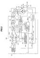
- Fig. 2 is a block diagram of a configuration of a controller of a field winding type synchronous motor according to an embodiment of the present invention. Reference numerals that are the same as those of Fig. 1 denote the same section.
- a motor control unit 100 shown in Fig. 2 performs feedback control on the d-axis current Id, the q-axis current Iq, and the field current If of the motor 20.
- a torque command Tr* to be inputted to the motor control unit 100 is given from the engine control unit 30.
- the torque command Tr* is outputted by the engine control unit 30 according to the vehicle condition.
- the driving mode MODE
- the torque command Tr* for example, to ONm.
- the driving mode is set to the 4WD standby mode, and the torque command Tr* to a first predetermined value.
- the driving mode is set to the 4WD mode, and then the torque command Tr* is gradually increased up to a second predetermined value (second predetermined value > first predetermined value).
- second predetermined value > first predetermined value
- the motor control unit 100 includes a current command determination section 110; a d-q/three-phase converter 120; a PWM converter 130; a motor current detection section 140; a three-phase/d-q converter 150; a pole position and rotational speed detection section 160; a duty converter 170; an Id-If noninterference compensation amount calculation section 180; controllers CNT1, CNT2, and CNT3; subtractors DF1, DF2, and DF3; and an adder AD1.
- the current command determination section 110 of the motor control unit 100 determines each of a command value Id* of the d-axis current Id, a command value Iq* of the q-axis current Iq, and a command value If* of the field current If based on a torque command Tr* inputted from the engine control unit 30 and a rotational speed ⁇ of the motor detected by the pole position and rotational speed detection section 160.
- a method of determining a current command it is possible to use a method of calculating a current command value based on the torque formula of the motor or a method of searching for each current command value in a data table stored in advance in a ROM area of the controller using Tr* and ⁇ as arguments.
- a rotor speed ⁇ m of the motor is calculated by the pole position and rotational speed detection section 160 based on a position signal PLS from a position sensor 24 attached to a revolving shaft of the motor 20.
- the d-axis current Id and the q-axis current IqIq are not detected directly from the motor current.
- a three-phase current of the motor 20 is detected by a current sensor CS, and physical values Iu, Iv, and Iw of the three-phase ac current are set by the motor current detection section 140.
- the three-phase/d-q converter 150 calculates detection values Id ⁇ and Iq ⁇ of the d-axis current and the q-axis current, respectively, based on the physical values Iu, Iv, and Iw of the three-phase ac current and a rotor magnetic pole position ⁇ of the motor 20 obtained by the pole position and rotational speed detection section 160.
- the subtractor DF1 calculates a difference between the command value Id* of the d-axis current Id and the calculated detection value Id ⁇ of the d-axis current.
- the subtractor DF2 calculates a difference between the command value Iq* of the q-axis current Iq and the calculated detection value Iq ⁇ of the q-axis current.
- the controller CNT1 calculates a voltage command Vd* of the d-q coordinates from an output of the subtractor DF1.
- the controller CNT2 calculates a voltage command Vq* of the d-q coordinates from an output of the subtractor DF2.
- the voltage commands Vd* and Vq* are converted to ac voltage signals Vu*, Vv*, and Vw* by the d-q/three-phase converter 120 so as to be applied to the three-phase ac motor 20. Further, the ac voltage signals are subjected to pulse-width modulation (PWM) by the PWM converter 130 to obtain PWM signals Pu, Pv, and Pw for driving switching elements of the inverter 14. Then, based on these PWM signals Pu, Pv, and Pw, voltages are applied to a three-phase stator winding 22a of the motor 20 by the PWM inverter 14. Although the PWM signals are simplified as three lines in Fig. 2 , six signals are actually outputted so as to turn six switching elements of the PWM inverter ON or OFF.
- PWM pulse-width modulation
- a feedback control system is constituted for each of the d-axis current Id and the q-axis current Iq.
- the Id-If noninterference compensation amount calculation section 180 is used for noninterference control between the d and q axes in order to compensate the interference of an induced voltage occurring between the d and q axes. This section will be detailed later with reference to Fig. 3 .
- the motor 20 used in the present embodiment is a field winding type synchronous motor in which the field current If is sent to a field winding 22f to generate a magnetic flux of the rotor.
- the field current command value If* is determined by the current command determination section 110.
- the subtractor DF3 calculates a difference between the field current command value If* and a field current detection value If ⁇ detected by a current sensor 26.
- the controller CNT3 calculates a field voltage command Vf* based on an output of the subtractor DF3.
- the duty converter 170 performs duty conversion of the field voltage command Vf* and then drives a switching element SW1 so that a voltage equivalent to the field voltage command Vf* be applied to the field winding 22f.
- a noninterference component generally occurs between the d and q axes in an ac motor.
- the noninterference components refer to a q-axis induced voltage component eq shown in formula (1) acting on the d-axis voltage and a d-axis induced voltage component ed shown in formula (2) acting on the q-axis voltage.
- ⁇ is an angular velocity [rad/s] of the motor; Ld, a d-axis inductance [H]; Lq, a q-axis inductance [H]; and ⁇ , a field main magnetic flux [Wb].
- the Id-If noninterference compensation amount calculation section 180 is used for noninterference control between the d and q axes in order to compensate the interference of an induced voltage occurring between the d and q axes.
- the noninterference compensation amount calculation section 180 performs the presumed calculation of induced voltages or equivalents of each of the d and q axes, and compensates voltage commands Vd* and Vq* of the d-q coordinates, which are outputs of current control.
- a configuration and operation of the noninterference compensation amount calculation section 180 used for a controller of a field winding type synchronous motor according to the present embodiment will be explained below with reference to Figs. 3 to 6 .
- Fig. 3 is a block diagram of a configuration of a noninterference compensation amount calculation section 180 used for a controller of a field winding type synchronous motor according to an embodiment of the present invention. Reference numerals that are the same as those of Fig. 1 denote the same section.
- Fig. 4 is a diagram showing a principle of interference in a field winding type synchronous motor according to an embodiment of the present invention.
- Fig. 5 is a flow chart showing details of noninterference compensation in a field winding type synchronous motor according to an embodiment of the present invention.
- Figs. 6A to 6C are diagrams showing a principle of noninterference compensation in a field winding type synchronous motor according to an embodiment of the present invention.
- the field main magnetic flux ⁇ generated by sending a current to the field winding and a magnetic flux in a weak direction generated by the d-axis current interfere with each other.
- a principle of this interference will be explained below with reference to Fig. 4 .
- a field current If is sent to a field winding 22f to generate a magnetic flux ⁇ .
- a necessary field voltage Vf is applied between the terminals of the field winding 22f. Since the field current If is a dc current, it tends to constantly generate the magnetic flux ⁇ .
- the d-axis current can also be regarded as a dc current in the magnetic flux direction. Therefore, as a basic rule, the field winding 22f and a d-axis direction winding 22ad of the stator winding do not interfere with each other. However, if pulsation is caused by a disturbance, such as pulsation of the q-axis current, fluctuation of the motor speed, etc. as mentioned above, the magnetic flux is fluctuated by the pulsation of the d-axis current Id since the d-axis current Id tends to weaken the magnetic flux ⁇ .
- an induced voltage ef occurs in the field winding 22f. If the induced voltage ef occurs, the field current If fluctuates at the same frequency as that of a pulsating component of the d-axis current since the field current If flows by a potential difference between the field voltage Vf and the induced voltage ef.
- the magnetic flux ⁇ pulsates by fluctuations of the field current If, which may result in torque pulsation.
- FIG. 6A shows a condition where pulsation occurs in the d-axis current Id shown by a solid line when an original d-axis current Id1 shown by a dotted line is flowing.
- the pulsation of the d-axis current Id causes pulsation of the field current If shown by a solid line when an original field current If1 shown by a dotted line is flowing.
- the Id-If noninterference compensation amount calculation section 180 includes an Id variation calculation section 182, a Vf compensation calculation section 184, and an adjustment gain multiplier 186.
- the Id-If noninterference compensation amount calculation section 180 is provided between a feedback control system of the d-axis current Id and a feedback control system of the field current If.
- the Id variation calculation section 182 of the Id-If noninterference compensation amount calculation section 180 calculates time variation dId/dt of the d-axis current Id. Specifically, in Step S10 of Fig. 5 , the Id variation calculation section 182 stores a previous d-axis current value Id(n-1). Then, in Step S20, the Id variation calculation section 182 stores a present d-axis current value Id(n). Then, in Step S30, the Id variation calculation section 182 calculates a variation ⁇ Id of the d-axis current Id by taking a difference between the values of Step S10 and Step S20.
- Step S40 of Fig. 5 the Vf compensation calculation section 184 of Fig. 3 multiplies the time variation dId/dt of the d-axis current Id (obtained by the Id variation calculation section 182) by a d-axis inductance Ld or an equivalent to calculate a variation ⁇ d/dt of the induced voltage or an equivalent.
- the Id variation calculation section 182 calculates a time variation of Id, and the Vf compensation calculation section 184 multiplies the obtained value (dId/dt) by the d-axis inductance Ld or an equivalent, thus obtaining a variation of the induced voltage or an equivalent.
- Step S50 of Fig. 5 the adjustment gain multiplier 186 of Fig. 3 further multiplies the obtained value (d ⁇ d/dt) by an adjustment gain K to calculate an amount of compensation Vf2.
- a numerical value around 0.8 to 0.9 is selected as the adjustment gain K.
- the amount of compensation Vf2 calculated by the Id-If noninterference compensation amount calculation section 180 is a voltage equivalent to a pulsating component of the d-axis current Id, as shown in Fig. 6C . Then, the amount of compensation Vf2 calculated by the Id-If noninterference compensation amount calculation section 180 is added to a field winding voltage command Vf1 by the adder AD1, and then inputted to the duty converter 170 as a field winding voltage command Vf* subjected to noninterference compensation (Step S60 of Fig. 5 ).
- a time interval (dt) for obtaining the time variation dId/dt of the d axis is determined by the sampling interval of the controller and the frequency and amplitude, etc. of noise contained in a detected d-axis current.
- a calculation load can be reduced by taking a current variation over a time period that is an integral multiple of the sampling interval.
- a noise component contained in the current is eliminated by passing a d-axis current detection value through a low-pass filter 190, as shown by a dashed line of Fig. 2 to make it easier to detect a variation of the actual d-axis current.
- Fig. 7 is a block diagram of a configuration of a hybrid automobile mounting a controller of a field winding type synchronous motor according to an embodiment of the present invention. Reference numerals that are the same as those of Fig. 1 denote the same section.
- front wheels FW are driven by an engine 10 and a motor generator 20A.
- the power of the engine 10 and the motor generator 20A is transmitted to the front wheels FW through a transmission 16.
- the motor generator 20A having the same configuration as that of the field winding type synchronous motor of Fig. 1 is driven by the engine 10 and stores the generated power in a battery 40.
- the motor generator 20A is driven by the power of the battery 40 to drive the engine 10 and restart it after an idling stop.
- the motor generator 20A is driven by the power of the battery 40 to drive the front wheels FW.
- ac power outputted by the motor generator 20A is converted to dc power by an inverter 14 and then stored in the battery 40.
- the dc power of the battery 40 is converted to ac power by the inverter 14 and then supplied to the motor generator 20A.
- the rotational speed of the engine 10 is controlled by an engine control unit (ECU) 30.
- a motor control unit (MCU) 100 controls the inverter 14 based on a motor torque command value Tr* given from the engine control unit 30 to control a current to be supplied to a stator winding of the motor generator 20A.
- the motor control unit also controls a current to be sent to a field winding of the motor generator 20A so that a predetermined torque can be obtained from the motor generator 20A.
- the configuration of the motor control unit 100 is the same as that shown in Fig. 2 .
- the motor control unit 100 includes a noninterference compensation amount calculation section 180 making it possible to suppress torque pulsation of the motor generator 20A by applying Id-If noninterference control according to the present invention.
- the time variation of the d-axis current is calculated and then operation is performed so as to compensate an induced voltage occurring in the field winding based on the time variation, thus making it possible to suppress torque pulsation.
Applications Claiming Priority (1)
| Application Number | Priority Date | Filing Date | Title |
|---|---|---|---|
| PCT/JP2005/012735 WO2007007387A1 (fr) | 2005-07-11 | 2005-07-11 | Contrôleur de moteur synchrone de type à enroulement de champ, système de commande électrique, véhicule à quatre roues motrices électrique et véhicule hybride |
Publications (2)
| Publication Number | Publication Date |
|---|---|
| EP1906523A1 true EP1906523A1 (fr) | 2008-04-02 |
| EP1906523A4 EP1906523A4 (fr) | 2012-10-10 |
Family
ID=37636795
Family Applications (1)
| Application Number | Title | Priority Date | Filing Date |
|---|---|---|---|
| EP05765516A Withdrawn EP1906523A4 (fr) | 2005-07-11 | 2005-07-11 | Controleur de moteur synchrone de type a enroulement de champ, systeme de commande electrique, vehicule à quatre roues motrices electrique et vehicule hybride |
Country Status (5)
| Country | Link |
|---|---|
| US (1) | US8073600B2 (fr) |
| EP (1) | EP1906523A4 (fr) |
| JP (1) | JP4709218B2 (fr) |
| CN (1) | CN101194415B (fr) |
| WO (1) | WO2007007387A1 (fr) |
Cited By (11)
| Publication number | Priority date | Publication date | Assignee | Title |
|---|---|---|---|---|
| CN102263531A (zh) * | 2010-05-26 | 2011-11-30 | 洛克威尔自动控制技术股份有限公司 | 控制电机转矩的方法和装置 |
| WO2012131269A2 (fr) * | 2011-03-30 | 2012-10-04 | Renault S.A.S. | Systeme et procede de commande d'un moteur electrique a phases multiples prenant en compte les oscillations de courant |
| FR2978888A3 (fr) * | 2011-08-04 | 2013-02-08 | Renault Sa | Systeme et procede de commande d'une machine electrique a rejection d'harmoniques. |
| WO2015071576A1 (fr) | 2013-11-15 | 2015-05-21 | Renault S.A.S. | Procede et systeme de commande d'une machine electrique triphasee de vehicule automobile alimentee par des tensions hachees |
| WO2017089066A1 (fr) * | 2015-11-26 | 2017-06-01 | Robert Bosch Gmbh | Procédé permettant de détecter un état d'un réseau de bord |
| CN107161032A (zh) * | 2017-05-15 | 2017-09-15 | 深圳市瀚路新能源汽车有限公司 | 电动车驱动电机振动抑制控制方法和系统 |
| FR3073691A1 (fr) * | 2017-11-16 | 2019-05-17 | Renault S.A.S | Procede de commande d'une machine electrique synchrone |
| EP3466736A3 (fr) * | 2017-10-09 | 2019-06-12 | Ford Global Technologies, LLC | Véhicule électrique hybride plug-in à autonomie étendue |
| WO2022002491A1 (fr) * | 2020-06-30 | 2022-01-06 | Bayerische Motoren Werke Aktiengesellschaft | Système d'entraînement ayant une alimentation en harmoniques |
| RU2771632C2 (ru) * | 2017-11-16 | 2022-05-11 | Рено С.А.С | Способ управления синхронной электрической машиной |
| EP3117516B1 (fr) * | 2014-03-11 | 2022-10-12 | Renault s.a.s | Procédé et système de commande d'une machine électrique triphasée de véhicule automobile |
Families Citing this family (32)
| Publication number | Priority date | Publication date | Assignee | Title |
|---|---|---|---|---|
| EP1963220A4 (fr) * | 2005-12-20 | 2012-05-09 | Otis Elevator Co | Strategie de controle de commande d'ascenseur |
| JP5412772B2 (ja) * | 2008-09-08 | 2014-02-12 | 株式会社デンソー | 回転機の制御装置 |
| CN102326329B (zh) * | 2009-03-30 | 2015-12-16 | 株式会社日立制作所 | 交流电机的控制装置及交流电机驱动系统 |
| JP2011004506A (ja) * | 2009-06-18 | 2011-01-06 | Sanyo Electric Co Ltd | モータ制御装置 |
| CN101753091A (zh) * | 2009-12-30 | 2010-06-23 | 重庆红宇精密工业有限责任公司 | 永磁同步电机的电流环控制方法 |
| KR101382305B1 (ko) * | 2010-12-06 | 2014-05-07 | 현대자동차주식회사 | 하이브리드 차량용 모터 제어 장치 |
| CN102097994B (zh) * | 2011-01-26 | 2012-11-14 | 清华大学 | 一种发电机励磁智能开关 |
| WO2012144662A1 (fr) * | 2011-04-18 | 2012-10-26 | 서울대학교산학협력단 | Machine synchrone à enroulement comportant un objet mobile doté d'un circuit onduleur, et procédé de commande associé |
| JP5899695B2 (ja) * | 2011-08-05 | 2016-04-06 | 日産自動車株式会社 | トルク制御装置 |
| JP5626592B2 (ja) * | 2011-08-08 | 2014-11-19 | アイシン・エィ・ダブリュ株式会社 | 制御装置 |
| FR2982097B1 (fr) * | 2011-10-28 | 2015-01-16 | Valeo Equip Electr Moteur | Procede de pilotage d'une machine electrique tournante synchrone a double excitation et machine electrique tournante correspondante |
| DE102011086734B4 (de) * | 2011-11-21 | 2023-11-16 | Robert Bosch Gmbh | Verfahren zum Betreiben einer Energieversorgungseinheit für ein Bordnetz eines Kraftfahrzeugs |
| FR2993116B1 (fr) * | 2012-07-03 | 2014-06-27 | Renault Sa | Procede de commande d'un groupe motopropulseur et systeme correspondant |
| JP5660111B2 (ja) * | 2012-11-30 | 2015-01-28 | トヨタ自動車株式会社 | 電気自動車のモータルームにおけるケーブル配索構造 |
| GB201301259D0 (en) * | 2013-01-24 | 2013-03-06 | Rolls Royce Plc | Method of controlling an ac machine and controller for controlling an ac machine |
| CN105103435B (zh) * | 2013-04-10 | 2017-03-22 | 三菱电机株式会社 | 旋转机控制装置 |
| JP6115392B2 (ja) * | 2013-08-08 | 2017-04-19 | 日産自動車株式会社 | モータ制御装置 |
| JP6361178B2 (ja) * | 2014-03-07 | 2018-07-25 | 株式会社ジェイテクト | モータ制御装置及び電動パワーステアリング装置 |
| US9673742B2 (en) * | 2014-04-21 | 2017-06-06 | Ford Global Technologies, Llc | Controlling magnetic flux in an automotive electric machine |
| JP6375994B2 (ja) * | 2015-02-25 | 2018-08-22 | 株式会社デンソー | 回転電機の制御装置 |
| CN106314203B (zh) * | 2015-06-30 | 2019-04-19 | 南车株洲电力机车研究所有限公司 | 交流传动控制系统 |
| CN106160618B (zh) * | 2016-07-19 | 2019-04-12 | 合肥威博尔汽车技术有限公司 | 一种bsg电机的励磁电流调节方法 |
| US10989187B2 (en) * | 2016-11-17 | 2021-04-27 | Hangzhou Sanhua Research Institute Co., Ltd. | Control system and control method |
| CN106787995B (zh) | 2017-01-22 | 2020-02-28 | 精进电动科技股份有限公司 | 一种测试电机转子初始位置角的方法 |
| JP6870562B2 (ja) * | 2017-10-10 | 2021-05-12 | 株式会社デンソー | 回転電機の制御装置 |
| CN108322125B (zh) * | 2018-01-25 | 2020-11-03 | 上海电气富士电机电气技术有限公司 | 一种同步电机的转矩响应控制方法 |
| FR3077444B1 (fr) * | 2018-01-30 | 2020-01-10 | Valeo Equipements Electriques Moteur | Procede de gestion de coupure de couple moteur pour une machine electrique tournante |
| US10931221B2 (en) * | 2018-10-03 | 2021-02-23 | Exedy Corporation | Rotational electric machine, drive control system of vehicle, and storage medium having program executed by or caused to be executed by control apparatus of rotational electric |
| JP7131521B2 (ja) * | 2019-10-02 | 2022-09-06 | トヨタ自動車株式会社 | 回転電機及び回転電機の制御方法 |
| CN112600475B (zh) * | 2020-12-30 | 2023-02-28 | 广东美的白色家电技术创新中心有限公司 | 弱磁控制方法、弱磁控制装置、电机驱动器及家用电器 |
| CN115425884B (zh) * | 2022-11-03 | 2023-01-17 | 南京师范大学 | 一种电励磁双凸极电机励磁电流分段补偿的转矩抑制方法 |
| CN116131689B (zh) * | 2023-03-02 | 2023-08-18 | 南京航空航天大学 | 基于h桥变换器的电励磁双凸极电机转矩分配控制方法 |
Citations (4)
| Publication number | Priority date | Publication date | Assignee | Title |
|---|---|---|---|---|
| JPH08242600A (ja) * | 1995-03-01 | 1996-09-17 | Meidensha Corp | ハイブリッド励磁形永久磁石電動機の電流制御装置 |
| EP1129890A2 (fr) * | 2000-03-01 | 2001-09-05 | Hitachi, Ltd. | Système de générateur électrique pour véhicules et sa méthode de régulation |
| EP1187307A2 (fr) * | 2000-09-07 | 2002-03-13 | Robert Bosch Gmbh | Structure de commande pour machines électriques |
| EP1529679A2 (fr) * | 2003-11-04 | 2005-05-11 | Nissan Motor Company, Limited | Commande du moteur d'un véhicule |
Family Cites Families (20)
| Publication number | Priority date | Publication date | Assignee | Title |
|---|---|---|---|---|
| JPS6118386A (ja) | 1984-07-03 | 1986-01-27 | Toshiba Corp | 無整流子電動機 |
| JPH0634614B2 (ja) | 1986-11-25 | 1994-05-02 | 三菱電機株式会社 | 交流電動機の制御装置 |
| JP3095566B2 (ja) | 1993-02-10 | 2000-10-03 | 株式会社東芝 | 同期機の制御装置 |
| JP3331734B2 (ja) | 1993-05-18 | 2002-10-07 | 株式会社明電舎 | 回転電機の制御方式 |
| JPH09285088A (ja) * | 1996-04-12 | 1997-10-31 | Hitachi Ltd | 永久磁石回転電機及びそれを用いた電動車両 |
| JP3899668B2 (ja) * | 1998-04-28 | 2007-03-28 | 株式会社デンソー | 界磁巻線式同期機の駆動制御装置 |
| JP3622547B2 (ja) * | 1998-12-28 | 2005-02-23 | 株式会社日立製作所 | 同期電動機の制御装置 |
| JP2003037990A (ja) * | 2001-07-24 | 2003-02-07 | Hitachi Ltd | モータ制御装置 |
| JP3651595B2 (ja) * | 2001-12-13 | 2005-05-25 | 株式会社東芝 | 洗濯機のインバータ装置及び洗濯乾燥機のインバータ装置 |
| AU2003241781A1 (en) * | 2002-05-29 | 2003-12-12 | Naoyuki Kadoya | Motor generator |
| JP3881301B2 (ja) * | 2002-10-24 | 2007-02-14 | 三菱電機株式会社 | 車両用回転電機の制御法 |
| JP3797972B2 (ja) * | 2002-11-29 | 2006-07-19 | 三菱電機株式会社 | 車両用発電電動機システム |
| JP3591532B2 (ja) | 2002-12-20 | 2004-11-24 | 株式会社日立製作所 | ハイブリッド自動車及びその駆動装置 |
| JP2004328991A (ja) * | 2003-04-09 | 2004-11-18 | Nissan Motor Co Ltd | 車両の左右輪駆動装置 |
| JP4523240B2 (ja) * | 2003-04-23 | 2010-08-11 | 三菱電機株式会社 | 車両用電動発電装置 |
| JP4280573B2 (ja) * | 2003-07-31 | 2009-06-17 | トヨタ自動車株式会社 | 負荷駆動装置 |
| US7262536B2 (en) * | 2003-08-11 | 2007-08-28 | General Motors Corporation | Gearless wheel motor drive system |
| JP4425006B2 (ja) * | 2004-01-19 | 2010-03-03 | 三菱電機株式会社 | 車両用回転電機 |
| JP4156542B2 (ja) * | 2004-03-03 | 2008-09-24 | 三菱電機株式会社 | 車両用回転電機装置 |
| US7088077B2 (en) * | 2004-11-09 | 2006-08-08 | General Motors Corporation | Position-sensorless control of interior permanent magnet machines |
-
2005
- 2005-07-11 WO PCT/JP2005/012735 patent/WO2007007387A1/fr not_active Application Discontinuation
- 2005-07-11 CN CN2005800500675A patent/CN101194415B/zh not_active Expired - Fee Related
- 2005-07-11 JP JP2007524482A patent/JP4709218B2/ja not_active Expired - Fee Related
- 2005-07-11 EP EP05765516A patent/EP1906523A4/fr not_active Withdrawn
- 2005-07-11 US US11/914,883 patent/US8073600B2/en not_active Expired - Fee Related
Patent Citations (4)
| Publication number | Priority date | Publication date | Assignee | Title |
|---|---|---|---|---|
| JPH08242600A (ja) * | 1995-03-01 | 1996-09-17 | Meidensha Corp | ハイブリッド励磁形永久磁石電動機の電流制御装置 |
| EP1129890A2 (fr) * | 2000-03-01 | 2001-09-05 | Hitachi, Ltd. | Système de générateur électrique pour véhicules et sa méthode de régulation |
| EP1187307A2 (fr) * | 2000-09-07 | 2002-03-13 | Robert Bosch Gmbh | Structure de commande pour machines électriques |
| EP1529679A2 (fr) * | 2003-11-04 | 2005-05-11 | Nissan Motor Company, Limited | Commande du moteur d'un véhicule |
Non-Patent Citations (2)
| Title |
|---|
| George Ellis: "Observers in Control Systems", 2002, Academic Press, XP040425220, ISBN: 0-12-237472-X pages 41-44, * page 43; tables 3-1 * * |
| See also references of WO2007007387A1 * |
Cited By (20)
| Publication number | Priority date | Publication date | Assignee | Title |
|---|---|---|---|---|
| CN102263531B (zh) * | 2010-05-26 | 2015-02-25 | 洛克威尔自动控制技术股份有限公司 | 控制电机转矩的方法和装置 |
| CN102263531A (zh) * | 2010-05-26 | 2011-11-30 | 洛克威尔自动控制技术股份有限公司 | 控制电机转矩的方法和装置 |
| US9960720B2 (en) | 2011-03-30 | 2018-05-01 | Renault S.A.S. | System and method for controlling a multiphase electric motor while taking current oscillations into account |
| WO2012131269A2 (fr) * | 2011-03-30 | 2012-10-04 | Renault S.A.S. | Systeme et procede de commande d'un moteur electrique a phases multiples prenant en compte les oscillations de courant |
| FR2973607A1 (fr) * | 2011-03-30 | 2012-10-05 | Renault Sa | Systeme et procede de commande d'un moteur electrique a phases multiples prenant en compte les oscillations de courant. |
| WO2012131269A3 (fr) * | 2011-03-30 | 2013-07-18 | Renault S.A.S. | Systeme et procede de commande d'un moteur electrique a phases multiples prenant en compte les oscillations de courant |
| FR2978888A3 (fr) * | 2011-08-04 | 2013-02-08 | Renault Sa | Systeme et procede de commande d'une machine electrique a rejection d'harmoniques. |
| WO2015071576A1 (fr) | 2013-11-15 | 2015-05-21 | Renault S.A.S. | Procede et systeme de commande d'une machine electrique triphasee de vehicule automobile alimentee par des tensions hachees |
| FR3013535A1 (fr) * | 2013-11-15 | 2015-05-22 | Renault Sa | Procede et systeme de commande d'une machine electrique triphasee de vehicule automobile alimentee par des tensions hachees. |
| US9621091B2 (en) | 2013-11-15 | 2017-04-11 | Renault S.A.S. | Method and system for controlling an automotive vehicle three-phase electric machine supplied via chopped voltages |
| EP3117516B1 (fr) * | 2014-03-11 | 2022-10-12 | Renault s.a.s | Procédé et système de commande d'une machine électrique triphasée de véhicule automobile |
| US10992162B2 (en) | 2015-11-26 | 2021-04-27 | Robert Bosch Gmbh | Method for detecting a state of a vehicle electric system |
| WO2017089066A1 (fr) * | 2015-11-26 | 2017-06-01 | Robert Bosch Gmbh | Procédé permettant de détecter un état d'un réseau de bord |
| CN107161032A (zh) * | 2017-05-15 | 2017-09-15 | 深圳市瀚路新能源汽车有限公司 | 电动车驱动电机振动抑制控制方法和系统 |
| EP3466736A3 (fr) * | 2017-10-09 | 2019-06-12 | Ford Global Technologies, LLC | Véhicule électrique hybride plug-in à autonomie étendue |
| FR3073691A1 (fr) * | 2017-11-16 | 2019-05-17 | Renault S.A.S | Procede de commande d'une machine electrique synchrone |
| WO2019096630A1 (fr) * | 2017-11-16 | 2019-05-23 | Renault S.A.S | Procédé de commande d'une machine électrique synchrone |
| US11211886B2 (en) | 2017-11-16 | 2021-12-28 | Nissan Motor Co., Ltd. | Method for controlling a synchronous electrical machine |
| RU2771632C2 (ru) * | 2017-11-16 | 2022-05-11 | Рено С.А.С | Способ управления синхронной электрической машиной |
| WO2022002491A1 (fr) * | 2020-06-30 | 2022-01-06 | Bayerische Motoren Werke Aktiengesellschaft | Système d'entraînement ayant une alimentation en harmoniques |
Also Published As
| Publication number | Publication date |
|---|---|
| EP1906523A4 (fr) | 2012-10-10 |
| WO2007007387A1 (fr) | 2007-01-18 |
| JPWO2007007387A1 (ja) | 2009-01-29 |
| JP4709218B2 (ja) | 2011-06-22 |
| US20090071735A1 (en) | 2009-03-19 |
| CN101194415B (zh) | 2010-06-09 |
| CN101194415A (zh) | 2008-06-04 |
| US8073600B2 (en) | 2011-12-06 |
Similar Documents
| Publication | Publication Date | Title |
|---|---|---|
| US8073600B2 (en) | Controller of field winding type synchronous motor, electric drive system, electric four wheel driving vehicle, and hybrid automobile | |
| US7653466B2 (en) | Control apparatus for electric vehicles | |
| EP1646137B1 (fr) | Dispositif d'entrainement d'un moteur avec une fonction de contrôle de reduction d'ondulation pour le torque | |
| US7586278B2 (en) | Control apparatus for electric vehicles | |
| US7605552B2 (en) | Control apparatus for electric vehicles | |
| JP4591320B2 (ja) | モータ制御装置 | |
| US9413281B2 (en) | Apparatus for controlling AC motor | |
| US7443117B2 (en) | Control apparatus for electric vehicles | |
| EP1695862B1 (fr) | Véhicule électrique et méthode de contrôle | |
| US7808194B2 (en) | Control apparatus for electric vehicles | |
| WO2011108058A1 (fr) | Véhicule électrique et procédé pour commander celui-ci | |
| EP2159911A2 (fr) | Contrôleur de moteur | |
| GB2390767A (en) | Vector control system for permanent magnet synchronous motor | |
| JPH1118496A (ja) | 電気車の制御装置および制御方法 | |
| JP4400389B2 (ja) | 駆動モータ制御装置 | |
| US20070119634A1 (en) | Control apparatus and method for electric vehicles | |
| JP5236965B2 (ja) | モータの制御装置 | |
| JP2009220665A (ja) | 車両用駆動制御装置 | |
| WO2021186842A1 (fr) | Dispositif de commande de machine synchrone, procédé de commande de machine synchrone, et véhicule électrique | |
| JP6772501B2 (ja) | 自動車 | |
| JP2008141838A (ja) | モータ制御装置 | |
| JP6128016B2 (ja) | 交流電動機の制御装置 | |
| JP6128017B2 (ja) | 交流電動機の制御装置 | |
| JP4702120B2 (ja) | 車両用駆動制御装置 | |
| JP2020137234A (ja) | 駆動装置 |
Legal Events
| Date | Code | Title | Description |
|---|---|---|---|
| PUAI | Public reference made under article 153(3) epc to a published international application that has entered the european phase |
Free format text: ORIGINAL CODE: 0009012 |
|
| 17P | Request for examination filed |
Effective date: 20080211 |
|
| AK | Designated contracting states |
Kind code of ref document: A1 Designated state(s): DE FR |
|
| RBV | Designated contracting states (corrected) |
Designated state(s): DE FR |
|
| DAX | Request for extension of the european patent (deleted) | ||
| A4 | Supplementary search report drawn up and despatched |
Effective date: 20120912 |
|
| RIC1 | Information provided on ipc code assigned before grant |
Ipc: H02P 27/04 20060101ALI20120906BHEP Ipc: H02P 9/36 20060101ALI20120906BHEP Ipc: B60L 15/20 20060101ALI20120906BHEP Ipc: H02P 21/00 20060101AFI20120906BHEP Ipc: B60L 11/14 20060101ALI20120906BHEP Ipc: B60L 15/02 20060101ALI20120906BHEP Ipc: H02P 21/05 20060101ALI20120906BHEP |
|
| 17Q | First examination report despatched |
Effective date: 20120924 |
|
| STAA | Information on the status of an ep patent application or granted ep patent |
Free format text: STATUS: THE APPLICATION HAS BEEN WITHDRAWN |
|
| 18W | Application withdrawn |
Effective date: 20150629 |